

Page 1
Agilent Technologies
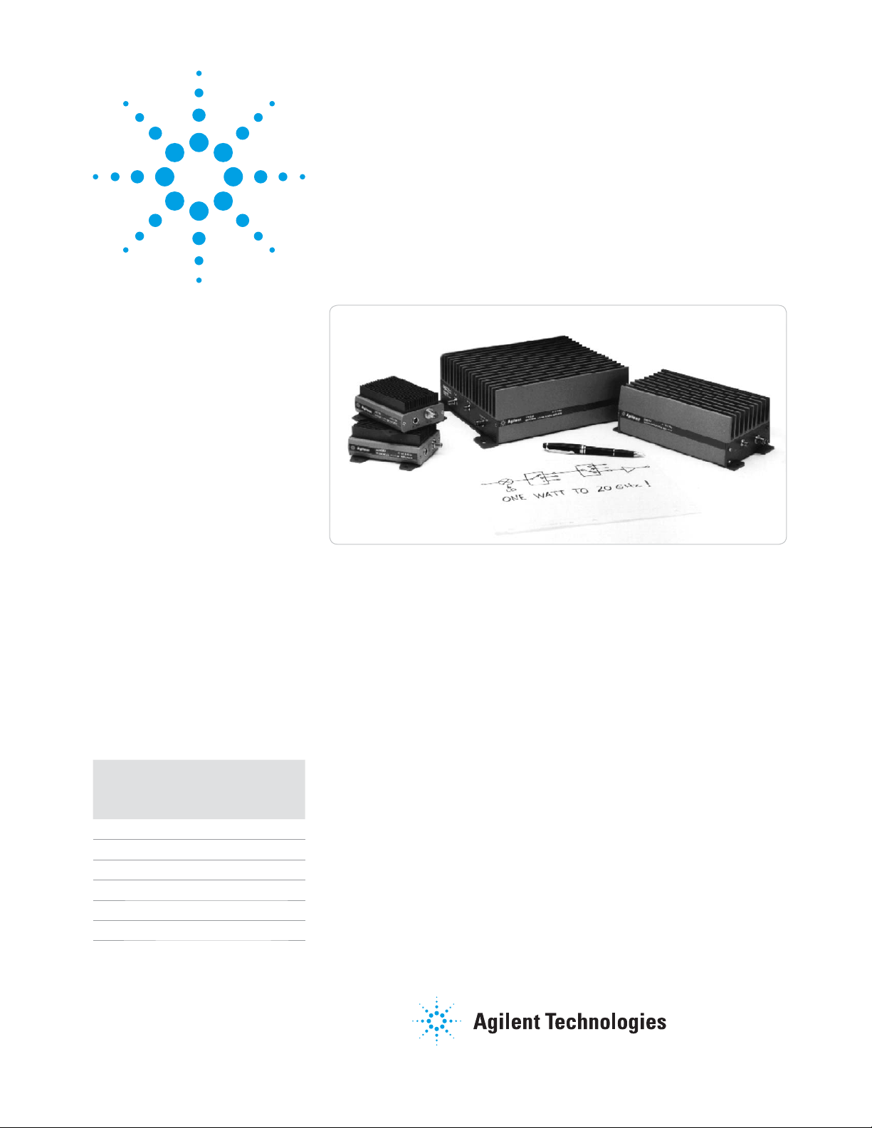
Microwave System
Amplifi ers
83006A 10 MHz to 26.5 GHz
83017A 500 MHz to 26.5 GHz
83018A 2 to 26.5 GHz
83020A 2 to 26.5 GHz
83050A 2 to 50 GHz
83051A 45 MHz to 50 GHz
Features
• Ultra broadband to 50 GHz
• Up to 1 watt output power
• Compact size
Agilent
model
(dBm)
83006A 0.01 to 26.5 20 13
83017A 0.5 to 26.5 25 18
83018A 2 to 26.5 27 24
83020A 2 to 26.5 30 30
83050A 2 to 50 21 18
83051A 0.045 to 50 23 12*
* 10 dbm 45 to 50 GHz
Frequency
(GHz)
Gain
(dB)
Pout
Agilent 83000A Series
Microwave System Amplifi ers
Technical Overview
The Agilent microwave system
amplifiers are compact, off-the-shelf
amplifiers designed for system
designers and integrators. This family
of amplifiers provides power where
you need it to recover system losses
and to boost available power in RF
and microwave ATE systems.
The ultrabroad bandwidth from
10 MHz to 50 GHz allows the designer
to replace several narrow bandwidth
amplifiers with a single Agilent
amplifier, eliminating the need for
crossover networks or multiple bias
supplies.
The 83050A power amplifier and
83051A preamplifier expand frequency performance to 50 GHz, while
the 1 Watt 83020A offers broadband
power to 26 GHz. The small amplifier
footprint allows for simple in-line
insertion to existing system blocks
that require amplification. The standard 83017A, 83018A, and 83020A
include internal directional detectors
for external leveling applications.
The 83020A is optionally available
without the coupler-detector providing
up to +30 dBm and +25 dBm, respectively. With excellent noise figure relative to their broad bandwidth and high
gain, these amplifiers significantly
improve system noise figure and
dynamic range. These products come
equipped with a low profile heat sink,
an integral mounting bracket, and a
two-meter DC power supply cable.
Thermal and power supply design
allows fast, easy integration into most
measurement systems.
Page 2
Applications
Small envelope size makes the
Agilent Technologies family of
microwave system amplifiers ideal
for automated test and benchtop
applications, offering the flexibility
to place power where you need it.
Boost source output power
Increase output power from microwave sources to increase test system
dynamic range. Drive high input power
devices such as TWTs, mixers, power
amps, or optical modulators. Drive
test devices into compression for
device characterization.
Recover systematic losses
The microwave system amplifiers
help solve the power loss from
connectors, cables, switches, and
signal routing components which
consume valuable source power.
Long transmission paths, common in
antenna applications, are particularly
susceptible to such losses.
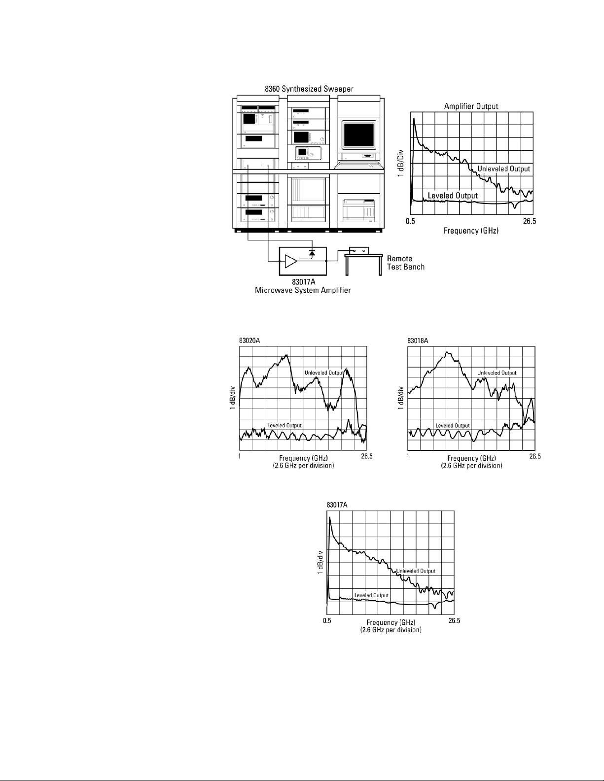
Level source power
By using feedback to an external
source ALC input, system designers
can level output power at the test
port, negating the effects of postsweeper reflections and losses.
Simply route the directional detector
output to the source external ALC
input connector. The figures at right
show typical results.
The 83020A, 83018A, and 83017A
feature an integral directional detector
to supply feedback. To level an 83006A
amplifier, use the 0.01 to 26.5 GHz
83036C directional detector or the
1 to 26.5 GHz 87300C coupler with
an 8474C detector.
2
Page 3
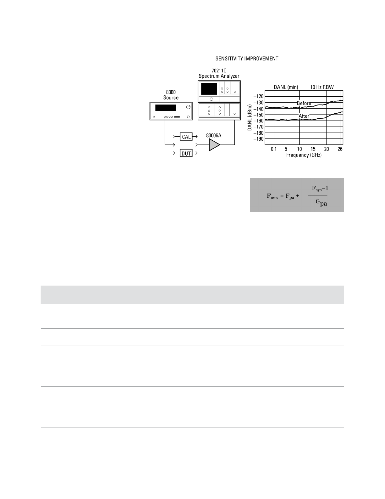
Improve Measurements
The 83006A, 83017A, and 83051A
preamplifiers increase the sensitivity and dynamic range of spectrum
analyzers. Add a preamplifier to
noise figure measurement systems
to significantly lower system noise
figure. The table below shows typical
system noise figure reduction achievable with these amplifiers. Note that
the reduced system noise figure is
dominated by the preamplifier noise
figure. See Application Note 57-2,
literature number 5952-3706.
Benchtop gain block
Benchtop microwave design tasks
often require amplification to measure low level output characteristics,
improve system dynamic range,
perform saturation tests, or boost
power levels. The Agilent family of
system amplifiers offers small size
and immediate, off-the-shelf solutions
to microwave design, production, or
test engineers.
Typical noise fi gure improvement
Amp
model
83006A 0.01–0.2 13 20 — 13.1 13.1 13.2 13.4 13.6 14.8
83017A 0.5–18 8 25 8.0 8.1 8.1 8.2 8.4 8.6 9.8
83018A 1–2 10 23 10.0 10.1 10.1 10.2 10.4 10.6 11.8
83020A 1–20 10 30 10.0 10.0 10.0 10.0 10.1 10.1 10.4
85050A 2–26.5 6 21 6.1 6.2 6.3 6.5 7.0 7.5 9.5
83051A 0.045–2 12 23 12.0 12.0 12.1 12.1 12.3 12.4 13.2
Freq
(GHz)
0.2–18 8 8.1 8.2 8.4 8.6 9.2 9.8 12.1
18–26.5 13 — 13.1 13.1 13.2 13.4 13.6 14.8
18–26.5 13 — 13.0 13.0 13.1 13.1 13.2 13.6
2–20 10 27 10.0 10.0 10.1 10.1 10.2 10.3 10.8
20–26.5 13 23 — 13.0 13.1 13.1 13.2 13.3 14.0
20–26.5 13 27 — 13.0 13.1 13.1 13.1 13.1 13.4
26.5–50 10 10.0 10.1 10.1 10.2 10.4 10.6 11.8
2–26.5 6 6.1 6.2 6.3 6.5 7.0 7.5 9.5
26.5–50 10 10.0 10.1 10.1 10.2 10.4 10.6 11.8
Max
NF(dB)
Pulse parameter measurements
Fast rise time and multi-octave
bandwidth make these amplifiers
attractive for fast pulse parameter
measurements. The 0.01, 0.5, and
2 GHz cutoff frequencies make them
more useful for RF or impulse measurements with low duration times.
Min
gain (dB)
System noise fi gure (Fsys) without preamp (dB)
13 15 18 20 23 25 30
All terms linear
3
Page 4

Product specifi cations
Model number 83006A 83017A 83018A
Frequency range 10 MHz–26.5 GHz 0.5–26.5 GHz 2–26.5 GHz
Small signal gain 20 dB min 25 dB min 23 dB typ 1–2 GHz
27 dB min 2–20 GHz
23 dB min 20–26.5 GHz
Small signal gain fl atness ±5 dB max 0.01–5 GHz ±5 dB max 0.5–2 GHz ±5 dB typ
±3 dB max 5–26.5 GHz ±5 dB max 2–26.5 GHz
Output power
(At P max)
(At 1 dB compression) +13 dBm min 0.01–20 GHz +18 dBm min 0.5–20 GHz +22 dBm typ 1–2 GHz
Leveled output power
1
Flatness
Noise fi gure <13 dB typ 0.01–0.1 GHz <8 dB typ 0.5–20 GHz <10 dB typ 1–20 GHz
Harmonics
(At spec’d value of P1 dBC)
Harmonics
(At spec’d max power)
Input SWR 2.6:1 2.6:1 3:1 typ 1–2 GHz
Output SWR 2.8:1 0.01–18 GHz 2.6:1 7.0:1 typ 1–2 GHz
Non-harmonically
related spurious
Rise time 400 ps typ 310 ps typ 275 ps typ
Third order intercept (TOI) 30 dBm typ at 2 GHz 30 dBm typ at 2 GHz 36 dBm typ 2–20 GHz
Impedance 50 Ω typ 50 Ω typ 50 Ω typ
Reverse isolation (typ) –65 dB –65 dB –55 dB at 1 GHz
Survival input power +23 dBm max +23 dBm max +23 dBm max
Power dissipation 6 W 9 W 24 W
1. At min specifi ed P1 dBC within given frequency band
2. P max measured with 0 dBm input
3. Option 001 Pmax +25 dBm 2–20 GHz, +22 dBm 20–26.5 GHz
+18 dBm typ 0.01–10 GHz +20 dBm typ 0.5–20 GHz +23 dBm typ 1–2 GHz
+16 dBm typ 10–20 GHz +15 dBm typ 20–26.5 GHz +24 dBm min 2–20 GHz
+14 dBm typ 20–26.5 GHz +21 dBm min 20–26.5 GHz
+10 dBm min 20–26.5 GHz +18 dBm–0.75 dB/GHz +22 dBm min 2–20 GHz
(20<f<26.5 GHz) +17 dBm min 20–26.5 GHz
N/A ±1.1 dB 0.5–26.5 GHz at 12 dBm
±1.5 dB 1–26.5 GHz at 17 dBm
±1.5 dB 0.5–20 GHz at 18 dBm
<8 dB typ 0.1–18 GHz <13 dB typ 20–26.5 GHz <13 dB typ 20–26.5 GHz
<13 dB typ 18–26.5 GHz
–25 dBc 0.01–11 GHz –20 dBc 0.5–11 GHz –22 dBc typ 1–2 GHz
–25 dBc typ 11–13.25 GHz –20 dBc typ 11–13.25 GHz –19 dBc 2–11 GHz
–19 dBc typ 11–13.25 GHz
N/A N/A –20 dBc typ 1–2 GHz
–17 dBc typ 2–11 GHz
–17 dBc typ 11–13.25 GHz
3:1 2–26.5 GHz
3.2:1 18–26.5 GHz 4.5:1 2–10 GHz
2.2:1 10–26.5 GHz
–65 dBc typ –65 dBc typ –65 dBc typ
20 dBm typ at 26.5 GHz 20 dBm typ at 26.5 GHz 31 dBm typ 20–26.5 GHz
+0.95 dB/GHz
2
2,3
2,3
4
Page 5

Product specifi cations (continued)
Model number 83020A 83050A 83051A
Frequency range 2–26.5 GHz 2–50 GHz 45 MHz–50 GHz
Small signal gain 30 dB typ 1–2 GHz 21 dB min 23 dB min
30 dB min 2–20 GHz
27 dB min 20–26.5 GHz
Small signal gain fl atness ±5 dB typ ±3.5 dB max ±3.5 dB max
2
Output power
(At P max)
+30 dBm typ 1–2 GHz
+30 dBm min 2–20 GHz
+30 dBm –0.7 dB/GHz
(20<f<26.5 GHz)
(At 1 dB compression) +28 dBm typ 1–2 GHz +15 dBm 2–40 GHz +8 dBm 45 MHz–45 GHz
+28 dBm min 2–20 GHz +13 dBm 40–50 GHz +6 dBm 45–50 GHz
+28 dBm–0.7 dB/GHz
(20<f<26.5 GHz)
Leveled output power
1
Flatness
±1.5 dB typ 1–26.5 GHz N/A N/A
At 23 dBm
Noise fi gure <10 dB typ 1–20 GHz <6 dB typ 2–26.5 GHz <12 dB typ 45 MHz–2 GHz
<13 dB typ 20–26.5 GHz <10 dB typ 26.5–50 GHz <6 dB typ 2–26.5 GHz
Harmonics
(At Spec’d value of P1 dBC)
–22 dBc typ 1–2 GHz –20 dBc typ 2–18 GHz –20 dBc typ 45 MHz–18 GHz
–20 dBc typ 2–11 GHz –18 dBc typ 18–25 GHz –18 dBc typ 18–25 GHz
–17 dBc typ 11–13.25 GHz
Harmonics
(At Spec’d max power)
–20 dBc typ 1–2 GHz N/A N/A
–17 dBc typ 2–11 GHz
–17 dBc typ 11–13.25 GHz
Input SWR 3:1 typ 1–26.5 GHz 2.1 max 2.1 max
Output SWR 7.0:1 typ 1–2 GHz 2.8 max 2–18 GHz 2.2 max
4.5:1 2–10 GHz 2.1 max 18–50 GHz
2.2:1 10–26.5 GHz
Non-harmonically
–65 dBc typ –50 dBc typ –50 dBc typ
related spurious
Rise time 375 ps typ 250 ps typ 225 ps typ
Third order intercept (TOI) 38 dBm typ 2–20 GHz 27 dBm typ 27 dBm typ
33 dBm typ 20–26.5 GHz
Impedance 50 Ω typ 50 Ω typ 50 Ω typ
Reverse isolation (typ) –55 dB –50 dB typ –50 dB typ
Survival input power +23 dBm max +20 dBm max +20 dBm max
Power dissipation 48 W 11 W 5 W
1. At min specifi ed P1 dBC within given frequency band
2. P max measured with +5 dBm input
3. Option 001 deletes detected output, for Pmax add 0.5 dBm 1–26.5 GHz
Special Applications: Higher performanc e models available upon request (i.e., higher power, etc.)
+20 dBm 2–40 GHz +12 dBm to 45 GHz
2,3
+19 dBm–0.2 dB/GHz +10 dBm 45–50 GHz
2,3
(40<f<50 GHz)
<10 dB typ 26.5–50 GHz
5
Page 6

Product specifi cations (continued)
Model number 83006A 83017A 83018A
*Bias voltage and current
(nominal) mA
RF connectors 3.5 mm (f) 3.5 mm (f) 3.5 mm (f)
Detector output N/A BNC (f) BNC (f)
Detector sensitivity N/A 15 μV/μW 4 μV/μW
Detector polarity N/A Negative Negative
Weight: net shipping 0.64 kg (1.4 lb) 0.64 kg (1.4 lb) 1.8 kg (4.0 lb)
*Do not apply positive voltage before negative voltage.
12 ±1 Vdc at 410 ±85 mA 12 ±1 Vdc at 780 ±140 mA 12 ±1 Vdc at 1940 ±123 mA
–12 ±1 Vdc at 10 ±5 mA –12 ±1 Vdc at 20 ±2 mA –12 ±1 Vdc at 10 ±5 mA
1.32 kg (2.9 lb) 1.32 kg (2.9 lb) 2.9 kg (6.4 lb)
Environmental specifi cations
Temperature coeffi cient
of gain
Operating temperature 0 to +55° C 0 to +55° C 0 to +55° C
Storage temperature –40 to +70° C –40 to +70° C –40 to +70° C
–0.07 dB/° C –0.1 dB/° C –0.13 dB/° C
Other environmental information
EMC1 IEC 61326:1997/EN 61326:1997
CISPR 11:1997/EN 55011:1998, Group 1, Class A
Safety IEC 348:1978/HD 401 S1:1981
CAN/CSA-C22.2 No. 231 (Series M-89)
Moisture resistance 65° C at 95% RH for 10 days per Mil-Std-883C method 1004.5
Random vibration 5.2 G (rms) to 2000 Hz per Mil-Std-883C method 2026 test condition 11A
Shock 1500 G (peak), 0.5 ms per Mil-Std-883C method 2002.3 test condition B
Altitude, non-operating 15,000 m per Mil-Std-883C method 1001 test condition C
1. This ISM device complies with Canadian ICES-001. Cet appareil ISM est conforme a la norme NMB-001 du Canada.
6
Page 7

General specifi cations (continued)
Model number 83020A 83050A 83051A
*Bias voltage and current
(nominal)
RF connectors 3.5 mm (f) 2.4 mm (f) 2.4 mm (f)
Detector output BNC (f) N/A N/A
Detector sensitivity 1 μV/μW N/A N/A
Detector polarity Negative N/A N/A
Weight: net shipping 3.9 kg (8.5 lb) 0.64 kg (1.4 lb) 0.64 kg (1.4 lb)
*Do not apply positive voltage before negative voltage.
15 ±1.5 Vdc at 3200 ±800 mA 12 ±1 Vdc at 900 ±110 mA 12 ±1 Vdc at 314 ±34 mA
–15 ±0.5 Vdc at 20 ±5 mA –12 ±1 Vdc at 30 ±5 mA –12 ±1 Vdc at 30 ±5 mA
5.0 kg (11 lb) 1.32 kg (2.9 lb) 1.32 kg (2.9 lb)
Environmental specifi cations
Temperature coeffi cient
of gain
Operating temperature 0 to +55° C 0 to +55° C 0 to +55° C
Storage temperature –40 to +70° C –40 to +70° C –40 to +70° C
–0.19 dB/° C –0.09 dB/° C –0.09 dB/° C
Other environmental information
EMC1 IEC 61326:1997/EN 61326:1997
CISPR 11:1997/EN 55011:1998, Group 1, Class A
Safety IEC 348:1978/HD 401 S1:1981
CAN/CSA-C22.2 No. 231 (Series M-89)
Moisture resistance 65° C at 95% RH for 10 days per Mil-Std-883C method 1004.5
Random vibration 5.2 G (rms) to 2000 Hz per Mil-Std-883C method 2026 test condition 11A
Shock 1500 G (peak), 0.5 ms per Mil-Std-883C method 2002.3 test condition B
Altitude, non-operating 15,000 m per Mil-Std-883C method 1001 test condition C
1. This ISM device complies with Canadian ICES-001. Cet appareil ISM est conforme a la norme NMB -001 du Canada.
Specifi cations: describe the instrument’s warranted performance over the temperature range +20° C to +30° C (unless otherwise noted).
All specifi cations apply after the instrument’s temperature has been stabilized after one hour continuous operation. Typical characteristics
are intended to provide information useful in applying the instrument by giving typical but nonwarranted performance parameters. These
are denoted as “typical” or “nominal” and apply over the temperature range +20° C to +30° C.
Caution on Electrostatic Discharge: Electrostatic discharge (ESD) can damage or destroy electronic components. It is recommended that these
amplifi ers, like other electronic components, be installed and operated at a static-free workstation or in an environment where precautions
against ESD have been implemented.
7
Page 8

Graphical performance data
8
Page 9

Graphical performance data (continued)
9
Page 10

Amplifi er outline drawings
1
83006-60004 dc bias cable. Cable shipped with 83006A, 83017A, 83018A, 83050A, and 83051A.
1. Dimensions in millimeters and (inches).
10
Page 11

Amplifi er outline drawings (continued)
11
Page 12

Amplifi er outline drawings (continued)
12
Page 13

Power supply outline drawings
The 87421A power supply provides the dc power needed to bias the 83006A, 83017A, 83018A, 83050A, and 83051A.
The 87422A power supply provides the dc power needed to bias the 83020A, plus an additional ±12V dc output.
13
Page 14

Ordering Information
Other Instruments
Related Literature
Agilent 83006A, 83017A,
83050A, and 83051A
microwave system amplifi ers
Includes amplifier and part number
83006-60004, which is a two-meter
cable with a three-pin connector on
one end and three-wire leads on the
other end.
Agilent 83018A microwave
system amplifi er
Includes amplifier and part number
83006-60004, which is a two-meter
cable with a three-pin connector on
one end and three-wire leads on the
other end.
• Special applications: Higher
performance models available
upon request.
Agilent 83020A microwave
system power amplifi er
Includes amplifier and part number
83020-60004, which is a two-meter
cable with a fifteen-pin connector on
one end and three-wire leads on the
other end.
and Accessories
Agilent 83036C coaxial GaAs
directional detector
0.01–26.5 GHz, for use with the
83006A.
Agilent 87421A power supply
Includes power supply and part
number 83006-60005, which is a
two-meter cable with a three-pin
connector on one end and a D-subminiature connector on the other
end for direct connection to the
83006A, 83017A, 83018A, 83050A,
and 83051A.
Agilent 87422A power supply
Includes power supply and part
number 87422-60001, which is a
two-meter cable with fifteen-pin
connectors for direct connection to
the 83020A amplifier. One additional
cable, part number 83006-60005, is
provided for direct connection of the
12 Vdc output to a preamplifier such
as the 83006A, 83017A, 83018A,
83050A, or 83051A.
Agilent 83036C data sheet, 5952-1874
Agilent 87421A/87422A data sheet,
5091-4292E
• Option 001: Delete coupler/detector
providing higher output power.
• Special applications: Higher
performance models available upon
request.
14
Page 15

www.agilent.com
www.agilent.com/fi nd/mta
Agilent Email Updates
www.agilent.com/fi nd/emailupdates
Get the latest information on the
products and applications you select.
www.lxistandard.org
LXI is the LAN-based successor to
GPIB, providing faster, more effi cient
connectivity. Agilent is a founding
member of the LXI consortium.
Agilent Channel Partners
www.agilent.com/find/channelpartners
Get the best of both worlds: Agilent’s
measurement expertise and product
breadth, combined with channel
partner convenience.
Remove all doubt
Our repair and calibration services
will get your equipment back to you,
performing like new, when promised. You will get full value out of
your Agilent equipment throughout its lifetime. Your equipment
will be serviced by Agilent-trained
technicians using the latest factory
calibration procedures, automated
repair diagnostics and genuine parts.
You will always have the utmost
confi dence in your measurements.
For information regarding self
maintenance of this product, please
contact your Agilent offi ce.
Agilent offers a wide range of additional expert test and measurement services for your equipment,
including initial start-up assistance,
onsite education and training, as
well as design, system integration,
and project management.
For more information on repair and
calibration services, go to:
www.agilent.com/fi nd/removealldoubt
Product specifi cations and descriptions
in this document subject to change
without notice.
For more information on Agilent Technologies’ products, applications or services,
please contact your local Agilent office. The
complete list is available at:
www.agilent.com/find/contactus
Americas
Canada (877) 894-4414
Latin America 305 269 7500
United States (800) 829-4444
Asia Pacific
Australia 1 800 629 485
China 800 810 0189
Hong Kong 800 938 693
India 1 800 112 929
Japan 0120 (421) 345
Korea 080 769 0800
Malaysia 1 800 888 848
Singapore 1 800 375 8100
Taiwan 0800 047 866
Thailand 1 800 226 008
Europe & Middle East
Austria 43 (0) 1 360 277
1571
Belgium 32 (0) 2 404 93 40
Denmark 45 70 13 15 15
Finland 358 (0) 10 855 2100
France 0825 010 700*
*0.125 €/minute
Germany 49 (0) 7031 464
6333
Ireland 1890 924 204
Israel 972-3-9288-504/544
Italy 39 02 92 60 8484
Netherlands 31 (0) 20 547 2111
Spain 34 (91) 631 3300
Sweden 0200-88 22 55
Switzerland 0800 80 53 53
United Kingdom 44 (0) 118 9276201
Other European Countries:
www.agilent.com/find/contactus
Revised: October 1, 2009
© Agilent Technologies, Inc. 2002, 2008,
2010
Printed in USA, June 30, 2010
5963-5110E
 Loading...