

Page 1
Agilent 11896A and 8169A
Polarization Controllers
Product Overview
Automatic polarization state adjustments for polarizationdependent loss measurements and polarization synthesis
applications
Agilent 11896A: 980 nm and 1250 to 1640 nm
Agilent 8169A: 1400 to 1640 nm
Introduction
Developing and manufacturing
competitive, high-value components and systems for today's
optical industries require precise
attention to polarization sensitivity. The Agilent 11896A and
8169A Polarization Controllers
can help by saving time, money
and effort when measuring
and working with polarization
sensitive devices.
Polarization sensitive devices
include EDFAs, single-mode
fiber, polarization maintaining
fiber, isolators, switches, lasers,
couplers, modulators, interferometers, retardation plates and
polarizers. Device performance
will be affected by polarizationdependent efficiency, loss, gain
and polarization mode dispersion.
These polarization phenomena
enhance or degrade performance
depending on the application
area, be it communications,
sensors, optical computing or
material analysis.
An Important Part of a
Measurement System
A polarization controller is an
important building block of an
optical test system because it
enables the creation of all possible
states of polarization. The polarized signal stimulates the test
device while the measurement
system receiver monitors the
test device's responses to changing polarization. Sometimes
polarization must be adjusted
without changing the optical
power. At other times, polarization must be precisely synthesized to one state of polarization
(SOP) and then adjusted to
another SOP according to a
predetermined path. Each of
these needs are met sep-arately
using the Agilent 11896A or
8169A Polarization Controllers
(refer to Table 1 for application
details).
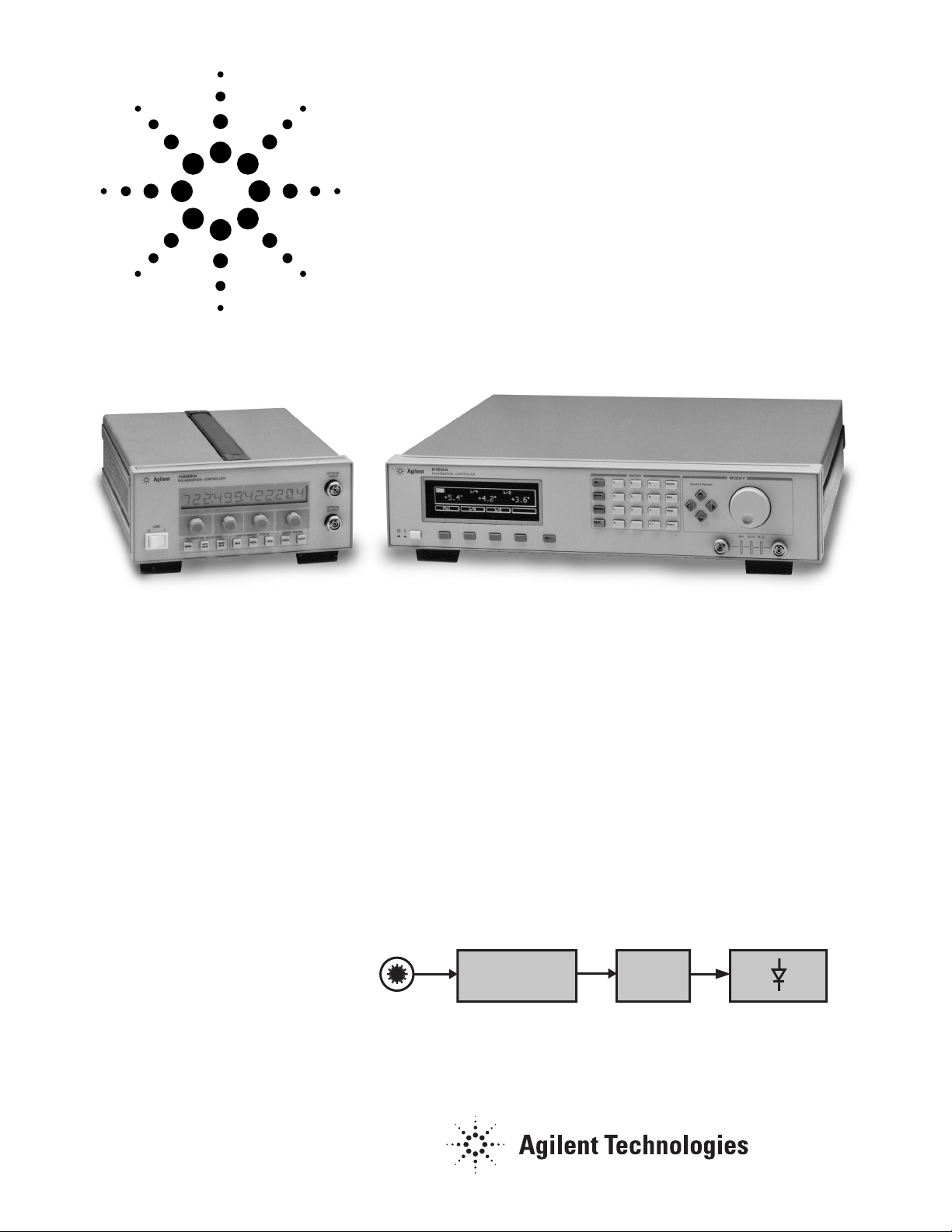
Figure 1. Conceptual block diagram of polarization controller applications.
Polarization
Controller
Lightwave
Source
Agilent 11896A
or 8169A
?
Test
Device
Optical
Receiver
Page 2
2
The Agilent 11896A
Polarization Controller
Measure very low PDL of DWDM
components
The Agilent 11896A motorized
polarization controller adjusts
polarization and not power. It’s
optical fiber loop design provides
all states of polarization with extremely small optical insertionloss variations (±0.002 dB) over
a wide spectral range (980 nm and
1250 to 1640 nm.) This performance
combination maximizes measurement accuracy for power sensitive
applications, such as polarizationdependent loss and gain, because
the measurement uncertainty
contributed by the polarization
controller is minimized. The 11896A
provides fast measurements of
DWDM components with a rotation rate of 360° in <0.5 seconds.
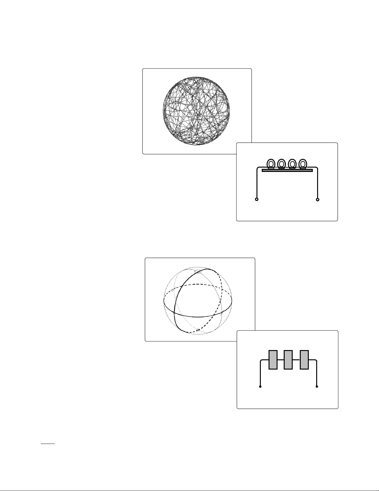
Figure 2. The Agilent 11896A
produces all states of polarization
and covers the entire Poincare
sphere1in a pseudo-random
manner.
Two Types of Polarization Controllers...
Figure 3. Agilent 11896A
Block Diagram
Figure 4. Orthogonal great circles
on the Poincare sphere1show how
the Agilent 8169A synthesizes
relative state-of-polarization points
according to a specified path.
Figure 5. Agilent 8169A
Block Diagram
1
The Poincare sphere is a three dimensional graphing system for viewing all possible states of polarization. Poincare sphere
display is provided by Agilent 8509A/B Lightwave Polarization Analyzer.
Optical
Input
Optical
Output
Linear
Polarizer
λ
/2
Plate
λ
/4
Plate
PDL measurement of DWDM components using Mueller
method is one of the main applications. The Mueller method
stimulates the test path with four precicely known states.
Precise measurement of the corresponding output intensities
allows calculation of the upper row of the Mueller matrix,
from which PDL is in turn calculated. This method is fast,
and ideal for swept wavelength testing of PDL.
The Agilent 8169A
Polarization Controller
´
The Agilent 8169A provides
polarization synthesis relative
to a built-in linear polarizer. The
quarter-wave plate and half-wave
plate are individually adjusted
to create all possible states of
polarization. Predeterministic
algorithms within the Agilent
8169A enable the transition path
from one state of polarization
on the Poincare sphere to another
to be specified along orthogonal great circles. These features
are important because device response data can be correlated
to specific states of polarization input to the test device.
λ
/4 Fiber Loop
Optical
Input
Optical
Output
Page 3

3
Application Description Agilent 11896A Application Agilent 8169A Application
1. Polarization adjustments (manual or automatic) with extemely
small power variations Yes No
2. Polarization synthesis No Yes
3. Complete, automatically stepped, adjustments of polarization Yes Yes
over the entire Poincare sphere (pseudo-random) (deterministic)
4. Single-wavelength polarization-dependent loss measurement Yes
1
Yes
5. Swept-wavelength polarization-dependent loss measurement Yes Yes
6. Polarization-dependent gain measurements of EDFA Yes
1
Yes
7. Polarization nulling for EDFA characterization No Yes
8. Polarization sensitivity measurements of optical coupling factor Yes Yes
(total power delta) (power delta vs SOP)
9. Optical waveguide TE/TM mode testing Yes Yes
10. Polarized beam alignment relative to principal polarization states Yes Yes
of the test device
11. Polarization adjustment of optical launch conditions for Yes Yes
polarization mode dispersion measurements
12. Simulate depolarized signals using rapid polarization scanning Yes Yes
1
The 11896A may be better suited for this application.
Ease of Use,
Flexibility and Speed
Four adjustment techniques
enhance the ease of use, flexibility
and speed of the Agilent 11896A
and 8169A. Precise manual
adjustments are made while
watching the front-panel display
and adjusting the front panel
knobs. Nine Save/Recall registers
enable random and rapid SOP
hopping between nine different,
user-set states of polarization.
Autoscanning continuously
sweeps over all states of polarization freeing the user from the
tiring, mundane task of manually tuning SOP across the
entire Poincare sphere. Multiple
polarization scan rates are available to match the speed of the
application; be it a five-second,
single-wave PDL measurement
or a three-minute, wavelengthscanning PDL measurement.
Autoscanning rates are also fast
enough to produce polarization
scrambling for some applications.
Remote interrogation of all
instrument settings and remote
control of all adjustment procedures are provided via GPIB.
General-Purpose Polarization
Controllers For a Wide Range
of Applications
The combined capabilities of the
Agilent 11896A and 8169A Polarization Controllers offer generalpurpose performance for a variety
of applications summarized in
Table 1. Measurement systems
are created by combining the
Agilent 11896A and 8169A with
other Agilent instruments as
indicated in Table 1; namely:
• Agilent 8153A Lightwave
Multimeter with Optical Head
• Agilent 71450B, 71451B or 71452B
Optical Spectrum Analyzer
• Agilent 8509B Lightwave
Polarization Analyzer.
...To Match Your Application Requirements
Table 1. Application matrix for Agilent 11896A and 8169A Polarization Controllers
Page 4

4
Specifications
Specifications
describe the instruments' warranted performance over the 0° C to +55° C temperature range after a one-hour warm-up period.
Characteristics
provide
information about non-warranted instrument performance. Specifications are given in normal type.
Characteristics are stated in italicized type.
Spliced fiber pigtail
interfaces are assumed for all cases except where stated otherwise.
Description Agilent 11896A Agilent 8169A
Operating Wavelength Range 980 nm and 1250 to 1640 nm 1400 to 1640 nm
Insertion Loss
1,3
<1.5 dB <1.5 dB
Variation over 1 full rotation ≤±0.002 dB
2
≤±0.03 dB
3
Variation over complete wavelength range ≤±0.1 dB
1
≤±0.1 dB
Polarization Extinction Ratio
4
>40 dB >45 dB (1530 to 1560 nm)
>40 dB (1470 to 1570 nm)
Characterisitic >30 dB (1400 to 1640 nm)
Polarization Adjustment
Resolution
4
0.18° 0.18°
(180°/1000 encoder positions) (360°/2048 encoder positions)
Fast axis alignment accuracy at home position
5,6
±0.18° ±0.2°
Angular adjustment accuracy: minimum step size ±0.18° ±0.09°
greater than minimum step size
5
±0.18° <±0.5°
Settling time (characteristic) <1 sec <200 ms
Memory Save/Recall registers 9 9
Angular repeatability after Save/Recall
5,6
±0.18° ±0.09°
Number of scan rate settings 8 2
Maximum rotation rate
6
360°/sec 3600°/sec
Maximum Operating Input Power Limitation +23 dBm +23 dBm
Operating Port Return Loss (characteristic):
Total reflection >55 dB
4
—
Individual reflections >60 dB >60 dB
Power Requirements 47 to 63 Hz 48 to 60 Hz
90 to 250 Vrms 100/120/220/240 Vrms
60 VA max 45 VA max
Weight: 4.5 kg (10 lb) 9 kg (20 lb)
Dimensions: (H x W x D) 10 x 21.3 x 36 cm 10 x 42.6 x 44.5 cm
3.9 x 8.4 x 14.2 in 3.9 x 16.8 x 17.5 in
Ordering Information
Agilent 11896A Lightwave Polarization Controller
Optical Connectors (choose one)
81000AI Diamond HMS-10 connector
81000FI FC/PC/SPC connector
81000SI DIN 47256/4108 connector
81000VI ST connector
Accessories
11896A-025 One meter fiber extender with FC/PC connector
interfaces
11896A-1CM Rack mount kit
11896A-1CN Front handles
11896A-1CP Rack mount kit with handles
11896A-H98 980 nm wavelength operation (special order)
1
Guaranteed over a wavelength range from 1470 to 1570 nm; characteristic for a wavelength range from 1400 to 1640 nm.
2
Wavelength range 1250 to 1600 nm with 11896A-025 option only.
3
Only with 8169A-020 option.
4
Extinction ratio only refers to polarized portion of the optical signal.
5
Guaranteed by design (DAC resolution).
6
Angles are mechanical rotation angles of the wave plates.
Agilent 8169A Lightwave Polarization Controller
Polarization controller must be ordered with a connector option.
8169A-020 Pigtailed fiber ports
8169A-021 Straight contact connectors
7
8169A-022 Angled contact connectors
7
7
Two Agilent 81000xI-series connector interfaces required.
Page 5

Agilent Technologies’
Test and Measurement Support, Services, and Assistance
Agilent Technologies aims to maximize the value you receive, while minimizing your risk and
problems. We strive to ensure that you get the test and measurement capabilities you paid for and
obtain the support you need. Our extensive support resources and services can help you choose
the right Agilent products for your applications and apply them successfully. Every instrument and
system we sell has a global warranty. Support is available for at least five years beyond the
production life of the product. Two concepts underlie Agilent’s overall support policy: “Our
Promise” and “Your Advantage.”
Our Promise
Our Promise means your Agilent test and measurement equipment will meet its advertised
performance and functionality. When you are choosing new equipment, we will help you with
product information, including realistic performance specifications and practical recommendations
from experienced test engineers. When you use Agilent equipment, we can verify that it works
properly, help with product operation, and provide basic measurement assistance for the use of
specified capabilities, at no extra cost upon request. Many self-help tools are available.
Your Advantage
Your Advantage means that Agilent offers a wide range of additional expert test and measurement
services, which you can purchase according to your unique technical and business needs. Solve
problems efficiently and gain a competitive edge by contracting with us for calibration, extra-cost
upgrades, out-of-warranty repairs, and on-site education and training, as well as design, system
integration, project management, and other professional engineering services. Experienced Agilent
engineers and technicians worldwide can help you maximize your productivity, optimize the return
on investment of your Agilent instruments and systems, and obtain dependable measurement
accuracy for the life of those products.
By internet, phone, or fax, get assistance with all your test & measurement needs.
Online assistance:
www.agilent.com/comms/lightwave
Phone or Fax
United States:
(tel) 1 800 452 4844
Canada:
(tel) 1 877 894 4414
(fax) (905) 282 6495
China:
(tel) 800-810-0189
(fax) 1-0800-650-0121
Europe:
(tel) (31 20) 547 2323
(fax) (31 20) 547 2390
Japan:
(tel) (81) 426 56 7832
(fax) (81) 426 56 7840
Korea:
(tel) (82-2) 2004-5004
(fax)(82-2) 2004-5115
Latin America:
(tel) (305) 269 7500
(fax) (305) 269 7599
Taiwan:
(tel) 080-004-7866
(fax) (886-2) 2545-6723
Other Asia Pacific Countries:
(tel) (65) 375-8100
(fax) (65) 836-0252
Email: tm_asia@agilent.com
Product specifications and descriptions in this document subject to change without notice.
© 1994, 2002 Agilent Technologies, Inc.
Printed in USA February 25, 2002
5988-5659EN
 Loading...