

Page 1
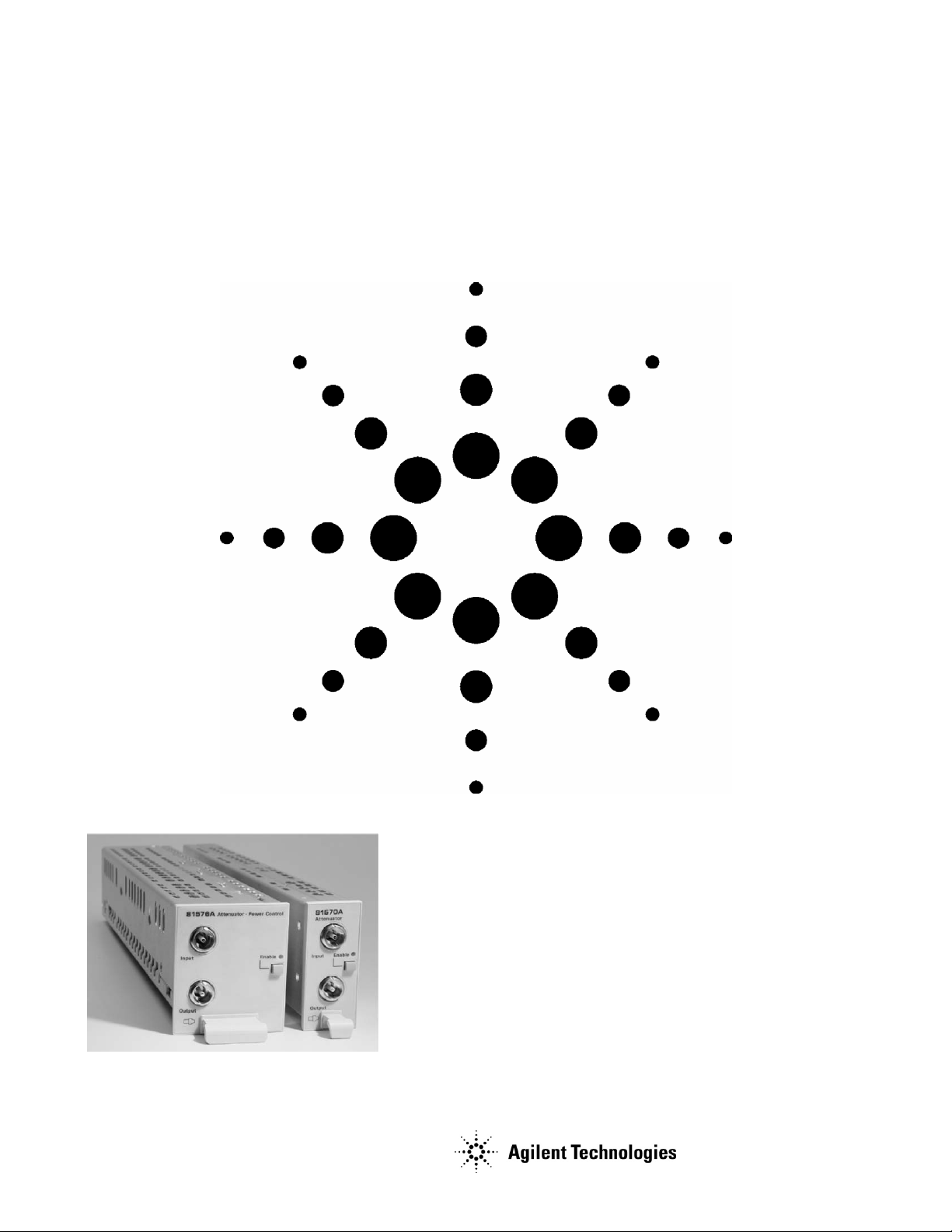
Agilent 8157xA Optical Attenuators
Technical Specifications
March 2006
Agilent’s 8157xA Variable Optical Attenuators are
instruments that attenuate and control the optical
power level of light in optical fibers.
As plug-in modules for Agilent’s Lightwave Solution
platform (8163A/B, 8164A/B, 8166A/B) they allow you
to set the attenuation factor and/or power level
manually, or remotely via a common computer
interface.
Their high accuracy combined with their flexibility
makes them ideal as test and measurement equipment
for the modern telecommunication industry.
Page 2

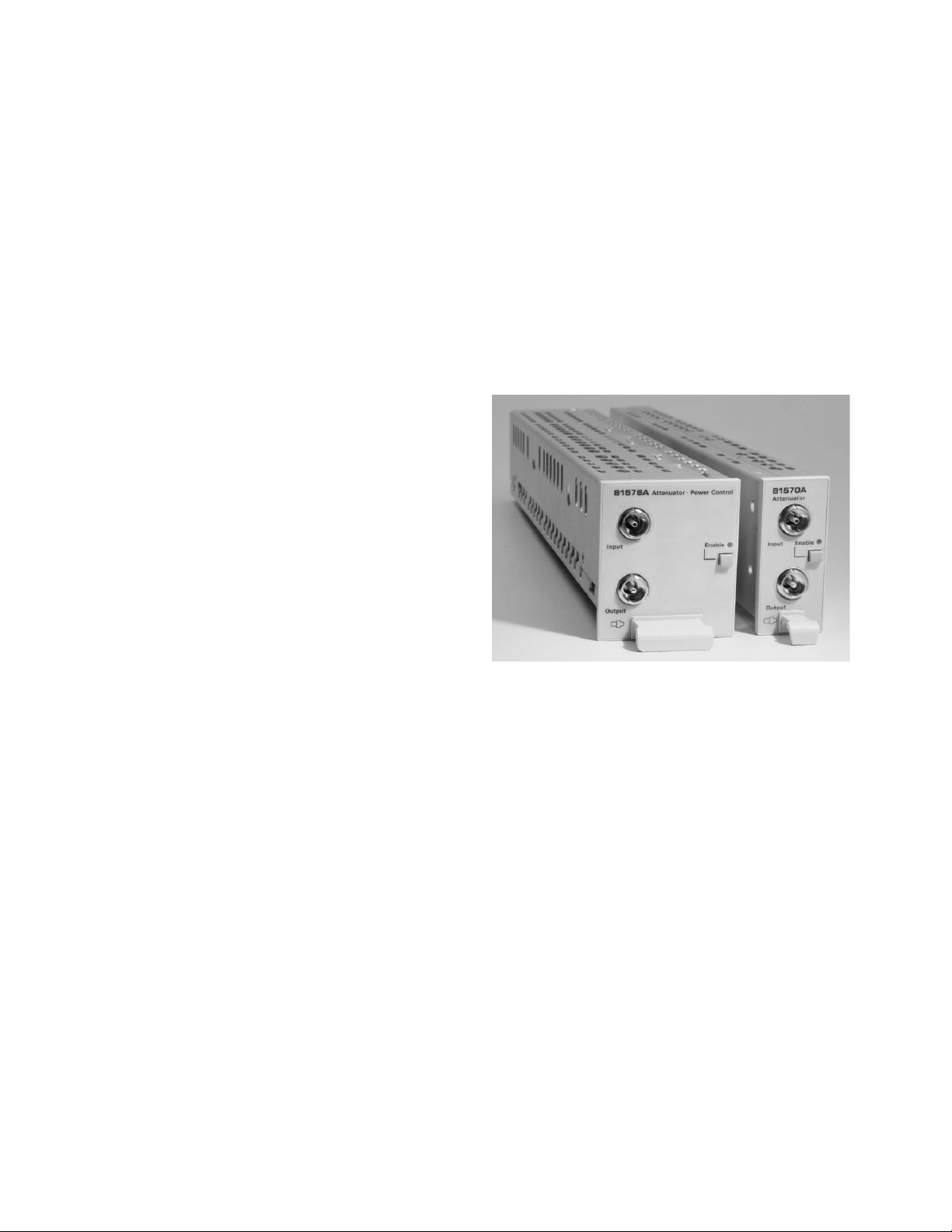
Modular Design for Lightwave Solution Platform
Agilent’s 8157xA variable optical attenuators are a family
of plug-in modules for Agilent’s Lightwave Solution
Platform 8163A/B, 8164A/B and 8166A/B. The attenuator
modules 81570A, 81571A and 81578A occupy one slot,
while modules 81576A and 81577A occupy two slots. With
17 slots, the Agilent 8166A/B Lightwave Multichannel
System can host up to 17 single slot modules or up to 8
dual slot modules.
Variable Optical Attenuators
Attenuators with Power Control
Agilent’s 81576A and 81577A attenuators feature power
control functionality that allows you to set the output
power level of the attenuator. The attenuator module uses
the feedback signal from a photodiode after a monitor tap,
both integrated in the module, to set the desired power
level at the output of the module. When the power control
mode is enabled, the module automatically corrects power
changes at the input to maintain the output level set by the
user. After an initial calibration for the uncertainties at
connector interfaces, absolute power levels can be set
with high accuracy. The absolute accuracy of these power
levels depends on the accuracy of the reference power
meter used for calibration.
The Agilent 81570A, 81571A and 81578A are small, costeffective attenuator modules with high resolution. They
feature excellent wavelength flatness and can handle high
input power levels. Combined with their low insertion loss,
they are ideal for optical amplifier test, such as
characterization of EDFAs and of Raman amplifiers, as
well as for other multi-wavelength applications, such as
DWDM transmission system test. Various calibration
features allow the user to set a reference power. Both the
attenuation and the power level, relative to the reference
power, can then be set and displayed in the user interface.
An integrated shutter, which can be used for protection
purposes, or to simulate channel drops, is included.
The multimode 81578A brings this performance to
multimode test and can be ordered for 50 µm or 62.5 µm
fiber.
These modules also feature high power handling capability
and excellent wavelength flatness for DWDM applications.
To set a total power level of a multi-wavelength signal, it is
necessary to determine the convolution of the signal’s
spectrum with the sensitivity of the photodiode over
wavelength. An enhanced calibration feature supports this
process and enables setting the integral power of a
DWDM signal with a known spectrum.
Page 2 of 8
Page 3
Calibration Processes
Comprehensive offset functionality in the firmware
enhances the calibration of the optical path in various test
set-ups. There is an offset for the attenuation factor, and
an independent offset for the output power level, to
calibrate for losses due to the patch cords and connectors.
Additionally, wavelength and offset value pairs can be
stored in a table to compensate for wavelength dependent
effects in the optical path of the set-up. This allows you to
set the optical power level at your Device Under Test.
Calibration is even easier and more convenient if the
reference power meter and the attenuator are hosted by
the same mainframe: All power related offsets can be
determined by a firmware function that reads a value from
the reference power meter. The difference between the
power value read by the reference power meter and the
actual value of the attenuator is automatically stored as
the offset.
Key Features
• High input powers up to 2 Watt
• Excellent wavelength flatness: typical ± 0.05 dB
• Low insertion loss: typical 0.7 dB
• Wide wavelength range: 1200 nm – 1700 nm (SM),
700 nm – 1400 nm (MM)
• High resolution: 0.001 dB
• Modular design allows up to 17 attenuators in one
mainframe
• Active power control options to set power levels
directly
• Comprehensive offsets allow easy calibration of the
set-up
• Integrated shutter
• Agilent’s versatile optical connector interfaces for all
common types of connectors
Applications
• Bit error ratio test
• Characterization of transceivers, receivers,
transmitters and line cards
• Test of single channel transmission systems
• DWDM channel equalization
• Loss simulation in fiber optic links
• Testing and calibrating the linearity of power meters
• Optical Amplifier Test
- Characterization of EDFAs
- Test of Raman amplifiers and SOAs
• Multi channel transmission system test
• Loss simulation of DWDM signals in fiber optic links
The Agilent 8157xA modules are produced to the ISO 9001
international quality system standard as part of Agilent's
commitment to continually increasing customer
satisfaction through improved quality control.
Page 3 of 8
Page 4

Variable Optical Attenuator Modules (Single Mode Fibers)
Connectivity straight connector
Fiber type
Wavelength range 1200 nm – 1700 nm
Attenuation range 0 – 60 dB
Resolution 0.001 dB
Repeatability
Accuracy (uncertainty)
Settling time
Transition speed typ. 0.1 – 12 dB/s
Attenuation flatness
Spectral ripple
Insertion loss
Insertion loss flatness
Polarization dependent loss
Return loss
Maximum input power
Shutter isolation typ. 100 dB
Dimensions (H x W x D) 75 mm x 32 mm x 335 mm (2.8” x 1.3” x 13.2”)
Weight 0.9 kg
Recommended recalibration
period
Operating temperature 10°C – 45°C
Humidity Non-condensing
Warm-up time 30 minutes
[1]
At constant operating conditions
[2]
Temperature within 23°C ± 5°C
[3]
Input Power < +30 dBm
[4]
For unpolarized light
[5]
Step size < 1 dB, for full range: typ. 6 seconds
[6]
Relative to reference at 0 dB attenuation
[7]
Linewidth of source ≥ 100 MHz
[8]
λ
disp
for attenuation > 20 dB:
add typ. 0.01 dB (α [dB] – 20) for 1520 nm < λ < 1620 nm
add typ. 0.02 dB (α [dB] – 20) for 1450 nm < λ < 1640 nm
[9]
For λ = 1550 nm ± 15 nm
[10]
Add typ. 0.1 dB for λ = 1310 nm ± 15 nm
[11]
Measured with Agilent reference connectors
[12]
Agilent Technologies Deutschland GmbH assumes no responsibility for damages caused by scratched or poorly cleaned connectors.
[1]
[1], [2], [3], [4]
[5]
typ. 100 ms
[1], [4], [6], [8]
[7]
[2], [4], [9], [10]
typ. 0.7 dB (excluding connectors)
[1], [11]
[2], [11]
[11]
typ. 45 dB
[12]
+33 dBm
set to 1550 nm; attenuation ≤ 20 dB;
81570A 81571A
angled connector
versatile interface
versatile interface
9/125 µm SMF28
± 0.01 dB
± 0.1 dB (at 1550 nm)
typ. ± 0.1 dB (1250 nm – 1650nm)
± 0.07 dB; typ. ± 0.05 dB (1520 nm < λ < 1620 nm)
typ. ± 0.10 dB (1450 nm < λ < 1640 nm)
typ. ± 0.003 dB
1.6 dB; typ. 1.0 dB (including connectors)
typ. ± 0.1 dB (1420 nm < λ <1615 nm)
[11]
[4]
0.08 dBpp; typ. 0.03 dBpp (at 1550nm ± 15nm)
typ. 57 dB
(at 1550nm ± 15nm)
(at 1550nm ± 15nm)
2 years
Page 4 of 8
Page 5

Variable Optical Attenuator Modules with Power Control (Single Mode Fibers)
Connectivity straight connector, versatile interface angled connector, versatile interface
Fiber type
Wavelength range 1250 nm – 1650 nm
Attenuation range 0 – 60 dB
Resolution 0.001 dB
Attenuation Setting Power Setting Attenuation Setting Power Setting
Repeatability
Accuracy (uncertainty)
Settling time
[6]
typ. 100 ms typ. 300 ms typ. 100 ms typ. 300 ms
Transition speed typ. 0.1 – 12 dB/s
Relative power meter uncertainty
Attenuation flatness
Spectral ripple
Insertion loss
[3], [5], [12], [13]
Insertion loss flatness
Polarization dependent loss
Return loss
[12], [14]
Maximum input power
[1], [3], [4], [5]
[7], [8]
[1], [5], [9], [10]
[11]
typ. 0.9 dB (excluding connectors)
[1], [14]
[3], [12], [14]
0.10 dBpp; typ. 0.05 dBpp
typ. 45 dB typ. 57 dB
[15]
+ 33 dBm
± 0.010 dB ± 0.015 dB
± 0.1 dB
Shutter isolation typ. 100 dB
Dimensions (H x W x D) 75 mm x 64 mm x 335 mm (2.8” x 2.6” x 13.2”)
Weight 1.3 kg
Recommended recalibration period 2 years
Operating temperature 10°C – 45°C
Humidity Non-condensing
Warm-up time 30 minutes
[1]
At constant operating temperature
[2]
Output power > -40 dBm, input power < +27 dBm. For input power > +27 dBm add typ. ± 0.01 dB
[3]
Temperature within 23°C ± 5°C
[4]
Input Power < +30 dBm; λ = 1550 nm ± 15 nm; typ. for 1250 nm < λ < 1650 nm
[5]
For unpolarized light
[6]
Step size < 1 dB; for full range: typ. 6 seconds
[7]
Wavelength and SOP constant; temperature constant and between 23°C ± 5°C; λ < 1630 nm; 1s averaging time
[8]
Output power >-45dBm,
input power ≤ 27dBm, for input power > + 27dBm add typ. ± 0.02dB
[9]
Relative to reference at 0 dB attenuation
[10]
λ
set to 1550 nm; attenuation ≤ 20 dB;
disp
for attenuation > 20 dB:
add typ. 0.01 dB (α [dB] – 20) for 1520 nm < λ < 1620 nm
add typ. 0.02 dB (α [dB] – 20) for 1450 nm < λ < 1640 nm
[11]
Linewidth of source ≥ 100 MHz
[12]
For λ = 1550 nm ± 15 nm
[13]
Add typ. 0.1 dB for λ = 1310 nm ± 15 nm
[14]
Measured with Agilent reference connectors
[15]
Agilent Technologies Deutschland GmbH assumes no responsibility for damages caused by scratched or poorly cleaned connectors.
81576A 81577A
9/125 µm SMF
[2]
± 0.010 dB ± 0.015 dB
± 0.1 dB
± 0.03 dB ± 200 pW
± 0.07 dB; typ. ± 0.05 dB (1520 nm < λ < 1620 nm)
typ. ± 0.10 dB (1450 nm < λ < 1640 nm)
typ. ± 0.003 dB
1.8 dB; typ. 1.2 dB (including connectors)
typ. ± 0.1 dB (1420 nm < λ < 1615 nm)
[14]
[5]
[2]
Page 5 of 8
Page 6

Variable Optical Attenuator Modules (Multimode Fibers)
The specifications below are valid for constant operating and signal launch conditions.
Connectivity straight connector versatile interface straight connector versatile interface
Fiber type
Wavelength range 700 nm – 1400 nm
Attenuation range 0 – 60 dB
Resolution 0.001 dB
Repeatability
Accuracy (uncertainty)
Settling time
Transition speed typ. 0.1 – 12 dB/s
Insertion loss
Return loss
Maximum input power
Shutter isolation typ. 100 dB
Dimensions (H x W x D) 75 mm x 32 mm x 335 mm (2.8” x 1.3” x 13.2”)
Weight 0.9 kg
Recommended recalibration period 2 years
Operating temperature 10°C – 45°C
Humidity Non-condensing
Warm-up time 30 minutes
[1]
At constant operating conditions
[2]
Effective spectral bandwidth of source > 5 nm
[3]
For mode launch conditions with NA = 0.2; for every ∆NA = 0.01 add typ. ± 0.01 dB
[4]
Temperature within 23°C ± 5°C and unpolarized light
[5]
At 850nm ± 15nm, 1310nm ± 15nm
[6]
Step size < 1 dB, for full range: typ. 6 seconds
[7]
The return loss is mainly limited by the return loss of the front panel connectors
[8]
Agilent Technologies Deutschland GmbH assumes no responsibility for damages caused by scratched or poorly cleaned connectors.
[1] [2] [5]
[1] [2] [3] [4] [5]
[6]
typ. 100 ms
[1] [2] [4] [5]
typ. 1.0 dB (NA = 0.1)
[2] [5] [7]
typ. 27 dB
[8]
+27 dBm
81578A #050 81578A #062
50/125 µm MMF 62.5/125 µm MMF
± 0.015 dB
typ. ± 0.15 dB (800 nm – 1350 nm)
± 0.2 dB (at 850 nm ± 15 nm, 1310nm ± 15 nm)
typ. 1.0 dB (NA = 0.1)
typ. 1.3 dB (NA = 0.2)
2.0 dB (NA = 0.2)
typ. 1.3 dB (NA = 0.2)
2.0 dB (NA = 0.2)
typ. 3.0 dB (NA = 0.27)
Page 6 of 8
Page 7

This page intentionally left blank
Page 7 of 8
Page 8

Agilent Technologies’ Test and Measurement Support, Services, and Assistance
Agilent Technologies aims to maximize the value you receive, while minimizing your risk and problems. We strive to ensure
that you get the test and measurement capabilities you paid for and obtain the support you need. Our extensive support
resources and services can help you choose the right Agilent products for your applications and apply them successfully.
Every instrument and system we sell has a global warranty. Support is available for at least five years beyond the
production life of the product. Two concepts underlie Agilent's overall support policy: "Our Promise" and "Your
Advantage."
Our Promise
Our Promise means your Agilent test and measurement equipment will meet its advertised performance and functionality.
When you are choosing new equipment, we will help you with product information, including realistic performance
specifications and practical recommendations from experienced test engineers. When you use Agilent equipment, we can
verify that it works properly, help with product operation, and provide basic measurement assistance for the use of
specified capabilities, at no extra cost upon request. Many self-help tools are available.
Your Advantage
Your Advantage means that Agilent offers a wide range of additional expert test and measurement services, which you can
purchase according to your unique technical and business needs. Solve problems efficiently and gain a competitive edge by
contracting with us for calibration, extra-cost upgrades, out-of-warranty repairs, and on-site education and training, as well
as design, system integration, project management, and other professional engineering services. Experienced Agilent
engineers and technicians worldwide can help you maximize your productivity, optimize the return on investment of your
Agilent instruments and systems, and obtain dependable measurement accuracy for the life of those products.
By Internet, phone, or fax, get assistance with all your test & measurement needs
Online assistance:
www.agilent.com/comms/lightwave
Phone or Fax
United States:
(tel) 1 800 829 4444
(fax) 1 800 829 4433
Canada:
(tel) 1 877 894 4414
(fax) 1 800 746 4866
Europe:
(tel) +31 20 547 2111
(fax) +31 20 547 2190
Japan:
(tel) 120 421 345
(fax) 120 421 678
Latin America:
(tel) +55 11 4197 3600
(fax) +55 11 4197 3800
Aust ralia:
(tel) 800 629 485
(fax) 800 142 134
Asia Pacific:
(tel) +852 800 930 871
(fax) +852 800 908 476
Product specifications and descriptions in this document subject to change without notice.
Copyri ght © 2006 Agilent Technol ogies
March 28, 2006
5988-2696EN
For related literature: please visit
www.agilent.com/comms/octcondition
 Loading...