

Page 1
The Standard in Pulse Generator
Technology
Key Features
· 33 MHz to 3 GHz Frequency
· <100 ps transition times
· <5 ps pulse jitter
· ±0.5% ps Width Accuracy
· ±100 ps Width Accuracy
· ±150 ps Delay Accuracy
· 1 or 2 Output Channels
· 2
23-1
PRBS Generation
· SCPI Programming Commands
Agilent Technologies
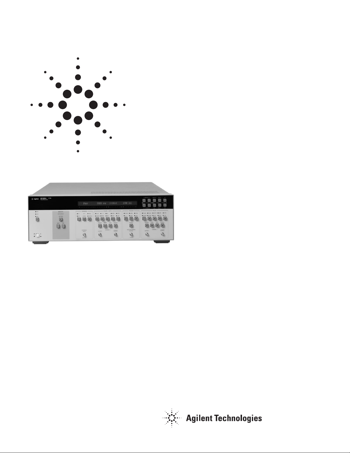
8133A 3 GHz Pulse Generator
The need for pulse generation is
fundamental to any device
characterization task. The ability to
emulate the pulse conditions to which
the device will be subjected is
essential. This emulation should
include both typical and worst case
conditions. Such accurate emulation
requires superlative signal integrity
and timing performance.
Setting Standards
The Agilent 8133A 3 GHz Pulse
Generator provides pulses with
programmable period from 333 ps to
30 ns, full 3 GHz pulse capability on
all channels. The pulse width can be
programmed too, along with a delay
or the interchannel delay. At these
frequency ranges the transition time
performance becomes critical; less
than 100 ps is specified, less than
60 ps is typical, so excellent signal
integrity is assured. And last but not
least, a typical jitter of 1 ps creates
precise and accurate timing
conditions.
Agilent Technologies
8133A 3 GHz Pulse Generator
Technical Specifications
Page 2

2
Pulse and Data Functionality
The 8133A ’s standard configuration
includes one pulse channel. A second
channel can be added. This can be
either:
· pulse/data channel (option 002)
· pulse channel (option 003)
Option 002 allows 32 bit, digital
pattern generation in NRZ and RZ
(50%duty cycle) mode.
Pulse/data channel 2 can also be
programmed to provide a pseudorandom binary~sequence (PRBS) of
data,a PRBS of 2
23-1
, which
conforms to CCITT 0.151.PRBS
generation capability finds a
particular application,in allowing the
instrument to be used as a data
source for eye diagram
measurements.
Human Interface
You will particularly appreciate the
interactive human interface when you
are operating the Agilent 8133A on
the bench. The easy access to all
parameters helps you concentrate on
the measurement task and react
immediately to unexpected problems.
The constant vernier steps for
parameters allow you to increment or
decrement through the entire
parameter range with a fixed stepsize,using only one key, which is
especially helpful when doing margin
testing.
The immediate error-guidance lets
you know what ’s wrong,with
messages like ”width> Period ”, and
how to fix it,with arrows indicating
that a parameter should be increased
or decreased. You can quickly recall
last valid setting if you prefer.
The Agilent 8133A is available in four different configurations. The differences are timing capabilities and number of channels with different
functionality.
8133A Option 001 Option 002 Option 003
Channel 1
Width or
Delay with Square
Delay also in Width
Mode
Delay also in Width
Mode
Delay also in Width
Mode
Channel 2
32-bit data
PRBS 223-1
Divided Square
Second Pulse Channel
with Width or Delay
with Square
Note: option 002 and 003 contain option 001
Page 3

3
Specifications
Specifications describe the instrument's warranted performance. Non-warranted values are described
as typical. All specifications apply after a 30 minute warm-up phase with 50 W source/load resistance
and separate channels. All specifications are valid from 0°C to 55°C ambient temperature.
Timing Characteristics
Measured at 50% amplitude at fastest transitions in continuous mode and 50 W source impedance.
Mainframe
Output module
Agilent 8133A
Pulse Channel 1
Delay Pulse Channel 1
Option 001
Pulse Channel 2
Option 003
Pulse/Data Channel 2
Option 002
Frequency Range
33.0 MHz to 3.0000 GHz
Period Range
333 ps to 30.303 ns
Timing resolution
3.5 digits, 1 ps best case
RMS Jitter (period, delay, width)
less than 5 ps (1 ps typical)
10 ps ( f<2 GHz: 5ps)
Accuracy
±±
0.5% (±± 0.1% typical)
Width range
[1]
150 ps to (period 150 ps) maximum 10.000 ns
Resolution
1ps
Accuracy
±±
100 ps (
±±
30 ps typical)
Duty Cycle
[2]
0% to 100%
Resolution
0.1%, best case 1
Add. Variable delay
Pulse mode: no
Square mode: 0.000 ns
10.000 ns
Pulse mode: -5.000
to + 5.000ns
Square mode: -5.000
ns to 15.000 ns
[3]
Pulse mode: no
Square mode: 0.000 ns to 10.000 ns
Channel 1 to Channel 2 Delay
[4]
Pulse mode: -5.000 ns to + 5.000 ns
Resolution
1 ps
Accuracy
[5]
±±
150 ps (
±±
30 ps typical)
[6]
±±
50 ps
Phase
[7]
0°° to 3600
°°
-3600°° to 3600
°°
-3600°° to 3600
°°
-3600°° to 3600
°°
Resolution
0.1°°, best case 1 ps
Skew
[8]
±±
5 ns
Notes:
[1]
The width can only be varied in Pulse mode. In square mode the duty cycle is fixed at 50%
[2]
Width and duty cycle are mutually exclusive. Duty Cycle settings and limits are subject to the same specifications and settings as
Width.
[3
]
Delay variation Channel 2 to Channel 1
[4]
The interchannel delay between Channel 1 and Channel 2 is the programmed delay of Channel
[5]
Any parameter variation
[6]
Only delay variation
[7]
Delay and Phase are mutually exclusive. Phase settings and limits are subject to the same specifications and settings as
[8]
Delay or Phase, plus Skew must be within the Delay Range
Repeatability: is typ. four times better
than accuracy.
Internal Clock Generation
The internal clock can be set in
frequency or period mode
External Clock
The external input signal determines
the timebase of the instrument. The
external period or frequency is
measured and displayed, allowing the
correct setting of Duty Cycle and
Phase also in External Clock mode.
External Frequency Counter Period
Range: 333 ps to 30.303 ns (300 ps to
500 ns typical)
Resolution: 1 ps
Accuracy: ± 0. 1 %
Page 4

4
ZERO-DELAY REFERENCE
Interchannel Timing Diagram
TIMEBASE External
Input
TRIGGER Output
PULSE Channel 1
Output
OPTION 001
PULSE Channel 1
Output (Option 001)
OPTION 002
(includes Option 001)
PULSE/DATA Channel 2
Output (Option 002)
PULSE/DATA Channel 2
Output (Option 002)
PULSE/DATA Channel 2
Output (Option 002)
TRIGGER Output
OPTION 003
(includes Option 001)
PULSE Channel 2
Output
EXT Divide mode
(divide by 1)
Divide mode
(divide by 1)
PULSE mode
SQUARE mode
PULSE mode
SQUARE mode
SQUARE mode
(divide by 1)
DATA RZ mode
DATA NRZ mode
Output
BIT 0 mode
(Option 002 only)
PULSE mode
SQUARE
24.8 ns typical
18 ns typical
Variable Delay
0 to 10 ns
Variable Delay
-5 to 5 ns
Variable Delay
-5 to 15 ns
Bit 0
2 ns typical
Variable Delay
0 to 10 ns
Variable Width
0.15 to 10 ns
Fixed 50% Duty-cycle
Variable Width
0.15 to 10 ns
Fixed 50% Duty-cycle
Fixed 50% Duty-cycle
Bit 0
1
1
Variable Width
0.15 to 10 ns
Fixed 50% Duty-cycle
Bit 2
1
Page 5

5
Frequency
Range: 33.0 MHz to 3.0000 GHz (2
MHz to 3.33 GHz typical)
Resolution: 100 kHz
Accuracy: ± 0. 1 %
External Input Divide
The external supplied frequency can
be divided.
Divide by: (1), 2, 4, 8, 16, 32, and 64.
The internal available frequency has
to be ³33 MHz to ensure that all
specifications are met.
The instrument will perform all
functions down to 3 MHz, except the
functions of the PULSE/DATA/
CHANNEL2.
External Input
Range: 33 MHz - 3 GHz
Interface: ac-coupled
Impedance: 50 W nominal
Minimum Swing
Pulse: 50% duty cycle, 300 mV,
tr < 3 ns
Sine: 0 dBm
Maximum amplitude: 3 Vpp, + 20 Vdc
PULSE CHANNEL 1
Delay
Delay has no period limitations.
Fixed delay between TRIGGER
Output to CHANNEL 1 Outputs: 18.8
ns nominal for trigger output divide
by 1
PULSE/DATA CHANNEL 2
(# 002)
Delay
Fixed delay from TRIGGER Output
to CHANNEL 2 Outputs.
Trigger on pulse: 18.8ns nominal
for trigger output divide by 1
Trigger on Bit 0: - 2.0 ns before Bit 0
nominal
Data
Selects Data mode. Further selection
between 32bit programmable data or
PRBS is required.
Divide
In Square mode the frequency of
CHANNEL 2 can be divided. Divide
by: (1), 2, 4, 8, 16, 32
To meet all timing specifications, the
internal (CHANNEL 2) frequency has
to be ³ 33 MHz.
32 BIT
32 bit of programmable data are
selectable.
PRBS
PRBS: 2
23 -1
,CCITT 0.151Norm
RZ / NRZ
Sets 32 bit data to Return To Zero/
Non Return to Zero mode.
RZ fixed duty cycle: 50% nominal
PULSE CHANNEL 2
(# 003)
Divide
In Pulse and Square modes, the frequency of Channel 2 can be divided
by 2, 4, 8, 16, 32 or 64.
The minimum Channel 2 frequency is
1 MHz.
The output voltage can be set in
amplitude/offset or high-/low level
mode. Levels double when driving
into open circuits.
Limit
Maximum high and low levels into 50
W can be limited to protect the device
under test. Pushing the limit key
declares present levels as limits
which then cannot be exceeded as
long as this mode is active.
Complement (not #002 PULSE/ DATA
CHANNEL 2)
Normal/complement selectable
Data (only #002 PULSE/DATA
CHANNEL2)
Provides logical complement of data
Disable
Relays connect/disconnect outputs
Connector Type
SMA (f) for all outputs and inputs
Mainframe Agilent 8133A
Amplitude
0.30 V to 3.00 V
Level window
-2 V to +4 V (-3 to +4 V typical)
Level Accuracy
± 2% of amplitude ± 2% of setting ± 20 mV
Resolution
10 mV
Output connectors
SMA Connectors on the front panel
Source Impedance
50 W
Skew between differntial outputs
< 20 ps nominal
Max. external voltage
± 3 V nominal
Short circuit current -120 mA max. £ Isc £ 160 mA nominal
Tranisition Times (10/90)
< 100 ps (60 ps typical)
Tranisition Times(20/80)
< 60 ps (40 ps typical)
Settiling time
1 ns
Overshoot/preshoot/ringing
< 15% of amplitude ± 20 mV Differential
Outputs
Level/Pulse Performance Characteristics
Page 6

6
TRIGGER Output
Conditions: fout > 33MHz
Trigger Channel Output
The output voltage can be set in
amplitude/offset or high- and low
level mode (50 W to 0 V).
Amplitude: (0.20 V typical) 0.50 V to
1.80 V nominal
Level Window: -4.00 V to +4.00 V
Resolution: 10 mV
Format: fixed Duty Cycle 50% nominal
Prop. delay External Input to Trigger
Channel Output: 6 ns nominal for
trigger output divide by 1 Maximum
external voltage: ± 4 V
Transition Times
20% - 80% of amplitude: < 100 ps
(< 60 ps typical)
Disable
A relay connects/disconnects the
trigger output
Divide
The trigger output frequency can be
divided.
Divide by: (1), 2, 4, 8, 16, 32, 64
Minimum output frequency: 33 MHz (3
MHz typical)
Bit 0 (PULSE/DATA CHANNEL 2 only)
The trigger output is synchronized to
Bit 0 of the 32 bit word in data mode.
It's a square wave signal divided by
32 with respect to the timebase
frequency.
Rearpanel Connectors
Agilent8133A: CHANNEL 1 ~ Output,
CHANNEL 1 - Input
Option 002: CHANNEL 2 - Output,
CHANNEL 2 - Input, Start/Stop Input
Option 003: CHANNEL 2 - Output,
CHANNEL 2 ~ Input
CHANNEL X Output amplitude: 2
Vpp, ac-coupled
CHANNEL X Input amplitude: max.
2.5 Vpp, ac-coupled, min. 1.0 Vpp,
ac-coupled
50% duty cycle
For proper operation the CHANNEL
X Outputs and Inputs have to be connected through the supplied rigid
coaxial links.
Start/Stop Input
Interface: dc-coupled
Impedance: 50n nominal
Transitions: < 1 ns
Start level: 0 V (default)
Stop level: - 0.4 V
The Start/Stop Input is used for the
PULSE/DATA CHANNEL 2 to hold
the data stream to setup a data
pattern and to start data generation
on a specific bit.
Additional Features
Non-volatile Memory
Current settings are saved on powerdown. Additionally 20 complete
settings can be stored.
GP-IB Capabilities
All modes and parameters are
programmable. Operates according
to IEEE standard 488.1 and 488.2,
1987. Conforms to the Standard
Commands for Programmable
Instruments (SCPI) 1992.0.
General Information
Environmental
Storage temperature: -40°C to +70°C
Operating temperature: O°C to 55°C
Humidity (0' C to 40' C): 95% R.H.
Power
110-120/220-240Vrms, ± 10%,
25OVA max., 47-63Hz
Weight
Net: 21.5 kg (48 lb)
Shipping: 29.0 kg (65 lb)
Dimensions
(HxWxD) 145 mm x 426 mm x 525
mm
(5.7 in x 16.75 in x 20.65 in)
Page 7

Ordering Information
Agilent 8133A 3 GHz Pulse
Generator
Option 001 Delay CHANNEL 1
Option 002 PULSE/DATA CHANNEL 2
Option 003 PULSE CHANNEL 2
Option 004 Standard Instrument
Note:
Option 002 and Option 003 con-
tain Option 001
Accessories
Agilent 1250-1462 Adapter SMA (m)
to SMA (f)
Agilent 8120-4948 50 W Cable, SMA
(m-m)
Agilent 8710-1582 Torque Wrench 5
in/lbs
Agilent 8493A Series Attenuators
Agilent 11667B Power Splitter
Agilent 15435A Transition Time
Converter 150 ps
Agilent 15432B Transition Time
Converter 250 ps
Agilent 15433B Transition Time
Converter 500 ps
Agilent 15434B Transition Time
Converter 1000 ps
Agilent 15438A Transition Time
Converter 2000 ps
7
Page 8

Related Agilent Literature
Agilent Family of Pulse/Pattern
Generators, brochure,
p/n 5980-0489E
Agilent Technologies'
Test and Measurement Support,
Services, and Assistance
Agilent Technologies aims to maximize the value
you receive, while minimizing your risk and
problems. We strive to ensure that you get the
test and measurement capabilities you paid for
and obtain the support you need. Our extensive
support resources and services can help you
choose the right Agilent products for your
applications and apply them successfully. Every
instrument and system we sell has a global
warranty. Support is available for at least five
years beyond the production life of the product.
Two concepts underlay Agilent's overall support
policy: "Our Promise" and "Your Advantage."
Our Promise
Our Promise means your Agilent test and
measurement equipment will meet its advertised
performance and functionality. When you are
choosing new equipment, we will help you
with product information, including realistic
performance specifications and practical recommendations from experienced test engineers.
When you use Agilent equipment, we can verify
that it works properly, help with product
operation, and provide basic measurement
assistance for the use of specified capabilities, at
no extra cost upon request. Many self-help tools
are available.
Your Advantage
Your Advantage means that Agilent offers a wide
range of additional expert test and measurement
services, which you can purchase according to
your unique technical and business needs. Solve
problems efficiently and gain a competitive edge
by contracting with us for calibration, extra-cost
upgrades, out-of-warranty repairs, and on-site
education and training, as well as design, system
integration, project management, and other professional services. Experienced Agilent engineers
and technicians worldwide can help you
maximize your productivity, optimize the return on
investment of your Agilent instruments and
systems, and obtain dependable measurement
accuracy for the life of those products.
By internet, phone, or fax, get assistance
with all your test & measurement needs
Online assistance:
www.agilent.com/find/assist
Phone or Fax
United States:
(tel) 1 800 452 4844
Canada:
(tel) 1 877 894 4414
(fax) (905) 206 4120
Europe:
(tel) (31 20) 547 2000
Japan:
(tel) (81) 426 56 7832
(fax) (81) 426 56 7840
Latin America:
(tel) (305) 267 4245
(fax) (305) 267 4286
Australia:
(tel) 1 800 629 485
(fax) (61 3) 9272 0749
New Zealand:
(tel) 0 800 738 378
(fax) 64 4 495 8950
Asia Pacific:
(tel) (852) 3197 7777
(fax) (852) 2506 9284
Product specifications and descriptions in this
document subject to change without notice.
Copyright Ó 2000 Agilent Technologies
Printed in Germany
28th November 2002
5980-1214E
For more information, please visit us:
www.agilent.com/find/pulse_generator
Get Free Email Updates
--------------------------------Keep up to date with Agilent's free
Email Updates. As a subscriber, you
will receive regular, customized email
updates on the topics you select.
Updates cover support, products and
services, applications, promotions,
events, and other areas. It is easy to
unsubscribe or change your preferences. Subscribe today:
http://www.agilent.com/find/emailupdates.
Agilent is committed to respecting
and protecting your privacy. Our
Privacy Statement at http://www.agilent.com/go/privacy describes our
commitment to you. Please direct any
questions about Agilent's privacy program to
pivacy_advocate@agilent.com.
www.agilent.com/find/emailupdates
 Loading...