

Page 1
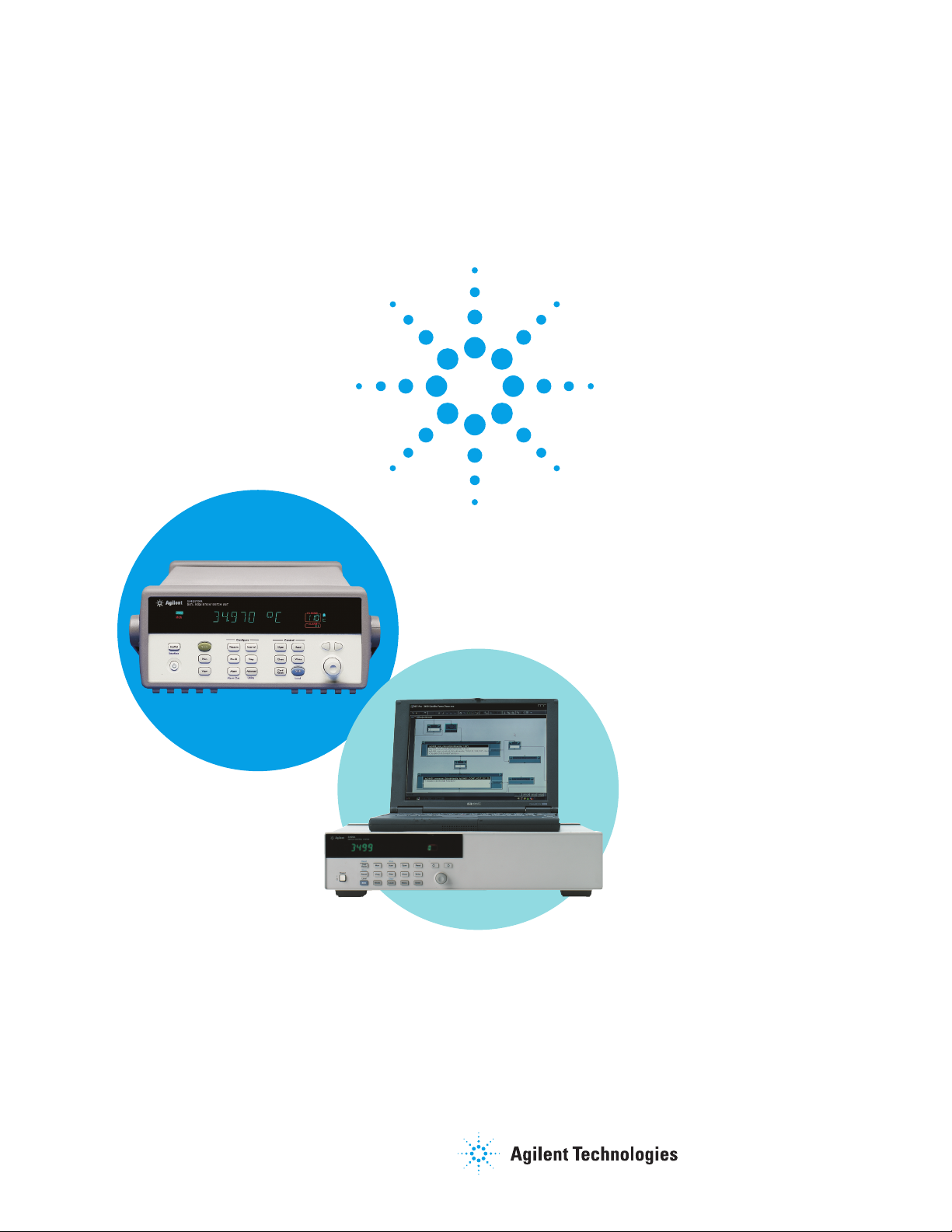
34970A
34970A and 3499A/B/C
Switch Systems
Which would be best for your application?
Product Overview
3499A/B/C
Page 2
2
Module and Mainframe
Selection
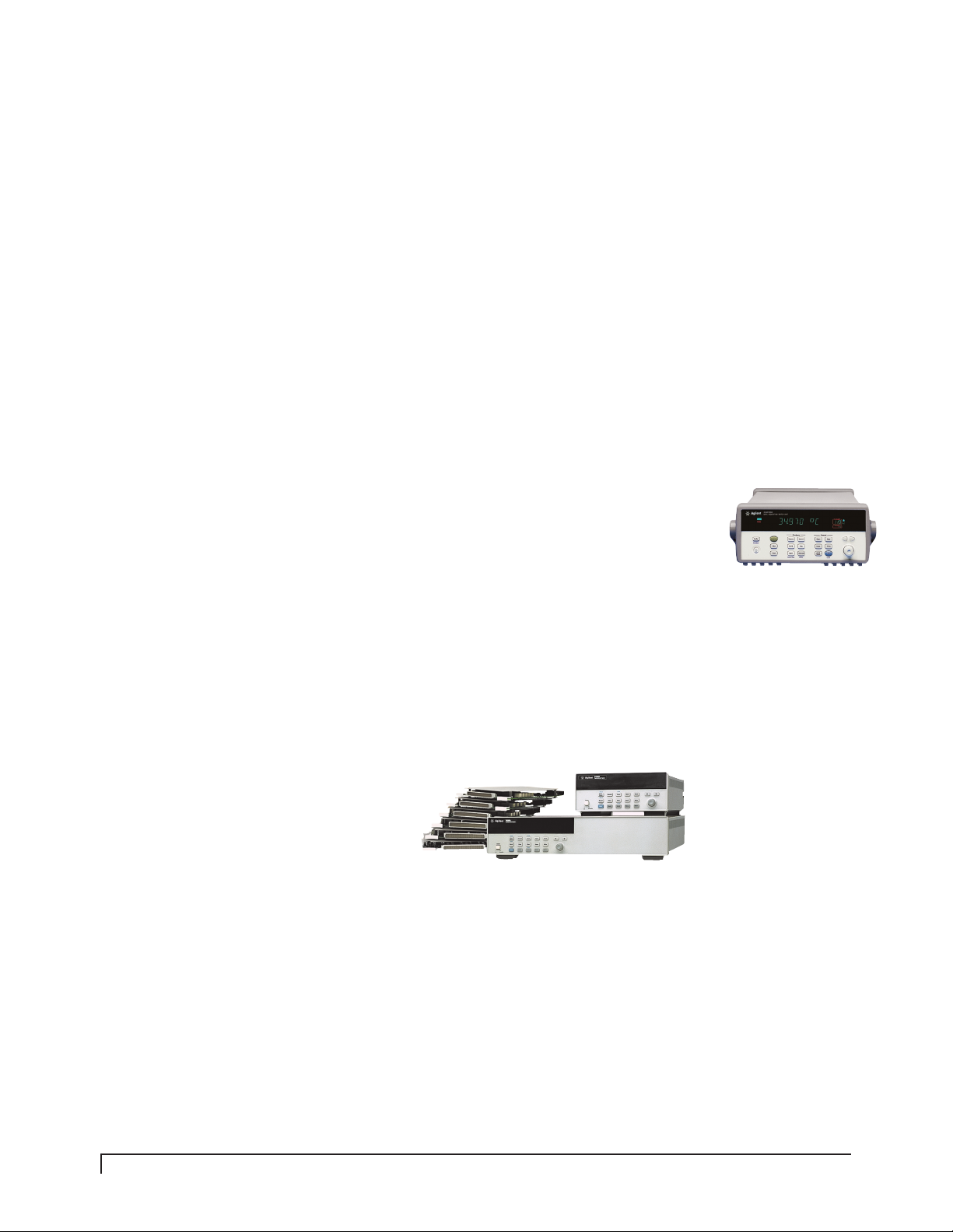
The 34970A and 3499A/B/C each
have a set of modules that can be
plugged into the mainframes. The
modules offer different types and
total number of switches and/or
measurement inputs and outputs.
You are able to select the modules
that provide the best solution to
the switch and measurement needs
of your specific application.
The 34970A System offers 8 different
plug-in modules. The modules
include both low-frequency and RF
multiplexers, a matrix switch, a
general-purpose switch, and a mul-
tifunction module that includes dig-
ital input/output,
analog output,
and totalizer
capabilities.
The 3499 Family offers a selection of
30 different plug-in modules includ-
ing multiplexer, fiber-optical
multiplexer, general-purpose relay,
matrix, digital I/O, VHF module, RF
module, Microwave module, Form-C
relay, and three multifunction mod-
ules. The 3499A/B/C mainframes
are also compatible with the earlier
generation HP 3488A
Switch/Control Unit
modules (4447xx).
Introduction
The 34970A Data Acquisition/Switch Unit and the 3499A/B/C
Switch/Control System are both very popular Agilent products.
Both systems offer a great solution for switching applications but
they each have differentiating features that will make them better
suited to specific applications. With this general product overview
you should have a better idea of what the 34970A and 3499A/B/C
products are, what they are capable of, and which one is the
best choice for your application. Module and mainframe selection,
user interface and measurements, module connections, and
system cost are the topics covered.
Page 3

3
The size of the 34970A and 3499A,
3499B, and 3499C mainframes
enable them to accommodate a
specific number of modules. The
34970A mainframe provides 3 slots
for modules to be installed. The
3499A, 3499B and 3499C differ only
in the number of slots that are avail-
able for modules. The 3499A can
accommodate up to 5 modules. The
3499B can accommodate 2 modules.
The 3499C has been designed with 9
electrical connections for modules,
and enough physical space for 14
modules. The additional space in
the 3499C mainframe enables the
2- or 3-slot RF and Optics modules
to be plugged in without giving up
a usable slot. The combination of an
individual module channel count,
and the total number of modules
that can be installed in one main-
frame determines the total number
of channels available for an appli-
cation. Table 1 (below) gives you an
idea of the maximum number of
channels possible for each main-
frame by showing the total number
of channels available when a high
channel count, 2-wire multiplexer
module is installed in every avail-
able slot. The 34970A and
3499A/B/C are best suited for appli-
cations with less than 60 channels
up to 360 channels. For applications
with a channel count greater than
360 channels, VXI switching is
recommended. Information on
Agilent VXI switching can be found
at www.agilent.com/find, then enter
System Switches.
The modules available for the
34970A and the 3499A/B/C are
listed below in Table 2. As you can
see from the chart there are many
different types of switch modules to
choose from. You can easily identify
a module or modules that provides
the best solution your test applica-
tion needs. For more specific
module specifications please refer
to the product data sheets at:
www.agilent.com/find/3499 and/or
www.agilent.com/find/34970A.
Mainframe Mainframe # of Module Maximum
Size Slots # of Channels
(2-wire)
34970A
1
/
2
Rack 3 60
2U
3499B
1
/
2
Rack 2 80
2U
3499A Full Rack 5 200
2U
3499C Full Rack 9 360
5U (electrical)
14
(physical)
Table 1. Mainframes
Module Type 34970A 3499A/B/C
Multiplexer 34901A 20 Ch armature N2260A 40 Ch armature
34902A 20 Ch reed N2266A 40 Ch reed
34908A 40 Ch 1 wire armature N2270A 10 Ch 1000V
44470A 10 Ch
44470D 20 Ch
General Purpose 34903A 20 Ch N2261A 40 Ch
N2267A 8 Ch, 8A
44471A 10 Ch
44471D 20 Ch
44477A 7 Ch SPDT (Form C)
Matrix 34904A 4x8 N2262A 4x8
44473A 4x4
Digital I/O N2263A 32-bit TTL
44474A 16-bit TTL
Multifunction 34907A Two 8-bit Dig I/O, N2264A 12 GP, 3 GP 5A, 16-bit Dig I/O
26-bit Event Counter, N2265A 4x4 matrix, 16-bit Dig I/O
Two 16-bit Analog out N2269A 2 DAC, 16-bit Dig I/O
Fiber-Optical N2280A Quad 1x2
Multiplexer N2281A Dual 1x4
N2282A Single 1x8
RF & Microwave 34905A Dual 4 Ch 2G 50 Ω N2268A Dual 1x4 3.5G 50 Ω
34906A Dual 4 Ch 2G 75 Ω N2272A Single 1x9 1.0G 50 Ω
N2276A Dual 1x6 20G 50 Ω
N2276B Relay driver (2 switches)
44472A Dual 1x4 300M 50Ω
44478A Dual 1x4 1.3G 50Ω
44478B Dual 1x4 1.3G 75Ω
44476A Triple 1x2 18G 50Ω
44476B Relay driver (2 switches)
Table 2. Modules
Page 4

4
Controlling the Switch Systems
and Making Measurements
The 34970A and 3499A/B/C both
use switching plug-in modules to
route signals to and from your test
system or multiplex signals to
external instruments. Measure-
ments and instrument control
capabilities of the 34970A and
3499A/B/C are what really differ-
entiate the products from one
another. The measurement capabil-
ities, control, monitoring ability,
and channel-scan rates for each of
the systems are included in this
section. Comparing this informa-
tion to the needs of your applica-
tion will make it easy for you to
identify which one of these sys-
tems is best for your application.
34970A
User Interface
The 34970A is easy to manually
control by pushing front-panel
buttons, or program using SCPI
(Standard Commands for Program-
mable Instruments) commands, or
the Plug&Play driver. BenchLink
Data Logger is a PC-based software
that comes with the 34970A. The
BenchLink Data Logger software
provides an easy way to set-up a
test to acquire measurement data.
The 34970A can store the data or
it can perform real-time display
and analysis of the incoming
measurements. These user inter-
faces can be used to make meas-
urements, control switch states,
or implement the scan and/or
monitor features.
Measurements & Alarms
The 34970A mainframe includes a
DMM that works in conjunction
with the Multiplexer plug-in mod-
ules 34901A, 34902A, and 34908A.
Up to 11 different measurements
(listed below) and engineering unit
conversions can be made using
these modules in the 34970A. The
34970A also has the capability to
flag any out-of range measurements
by comparing the input signals with
four different configurable limits
and activating an alarm.
34970A Measurements
• Temperature measured with
Thermocouples, RTDs, and
Thermistors
• DC and AC volts
• 2- and 4-wire Resistance
• Frequency and Period
• DC and AC current
• 4 alarms for High/Low or both
limits for each channel
• Digital I/O
• Analog outputs (DAC)
Scanning & Monitoring
The 34970A allows you to combine
a DMM (either internal or exter-
nal) with the multiplexer channels
to create a scan. During a scan,
the instrument connects the DMM
to the configured multiplexer
channels one at a time and makes
a measurement on each channel.
Automatic scanning and channel
monitoring can be started by man-
ually pressing a front-panel button,
by sending a software command,
an external TTL trigger pulse, an
alarm-initiated action, or an inter-
nally paced timer. During a scan
you can store up to 50,000 readings
in non-volatile memory. Each time
a new scan is started the 34970A
clears all the reading stored in
memory from the previous scan.
Since the 34970A switching is per-
formed as a scanner where only
one channel is closed at any time,
it may be important to your test
system to achieve or exceed a spe-
cific scan rate. Switching scan
rates for the 34970A modules are
shown in Table 3 at right. The
measurement scan rates vary
depending on the type of measure-
ment being made. See the 34970A
data sheet for measurement scan
rate details.
Continuous monitoring of a select-
ed channel, configured for meas-
urement, scan or digital I/O, can
be displayed even during a scan.
The 34970A takes readings on the
single channel as often as it can.
The readings displayed by the
monitor are not stored in memory
but the readings concurrently
taken during a scan will be stored
in memory.
Page 5

5
3499A/B/C
User Interface
The 3499A/B/C is easy to manually
control by pushing front-panel
buttons, or program using SCPI
(Standard Commands for Program-
mable Instruments) commands,
HP 3488A commands or the con-
venient Plug&Play or IVI drivers.
The 3499A/B/C user interfaces
can control switch states as well
as implement the scan and moni-
toring features.
Measurements
The 3499A/B/C provides a wide
assortment of switch capability as
well as Digital I/O and DAC. The
3499A/B/C is a valued component
in electronics test systems for
connecting instruments such as
DMMs, counters, spectrum analyz-
ers, LCR meters, signal sources,
power supplies and oscilloscopes.
The 3499A/B/C can also be used
for applications that require
microwave, and optics switching.
Innovative parallel driving circuits
are used in the 3499A/B/C mod-
ules to open/close switches simul-
taneously, which significantly
increases test throughput. The
3499A/B/C does not have an inter-
nal integrated DMM for making
measurements as the 34970A does.
Scanning & Monitoring
The 3499A/B/C can be program-
med to perform a channel scan, or
channel monitoring either from
the front panel, or by using software
commands. Up to 200 channels
and/or bits can be included in one
scan list. Once a scan is set up,
the user can select an arm source,
a trigger source, the number of
sweeps, and the delay time for
each individual channel.
The 3499A/B/C monitor feature
allows users to continuously moni-
tor a selected switch or module
status from the front display. The
3499A/B/C status can be a specific
switching channel, a digital I/O
port, or the state of all switches or
digital I/O on one plug-in module.
A single channel can be monitored
continuously even during an
instrument scan.
The 3499A/B/C is able to store
and recall instrument setups. The
instrument setups include the sta-
tus of relay channels, and/or the
static digital I/O state, module con-
figuration, as well as scanning
setups (scan lists, arm count,
arm source, etc.). Table 3 below
includes the scan rates for the
34970A and 3499A/B/C modules.
34970A 3499A/B/C
Module Type Modules Scan Rate Modules Scan Rate
Ch/s Ch/s
Multiplexer 34901A 20 Ch armature 120 N2260A 40 Ch armature 80
34902A 20 Ch reed 120 N2266A 40 Ch reed 350
34908A 40 Ch 1 70 N2270A 10 Ch 1000V 100
wire armature
44470A 10 Ch 43
44470D 20 Ch 43
General 34903A 20 Ch 120 N2261A 40 Ch 80
Purpose N2267A 8 Ch, 8A 20
Switch 44471A 10 Ch 43
44471D 20 Ch 43
44477A 7 Ch SPDT 43
(Form C)
Matrix 34904A 4x8 120 N2262A 4x8 80
44473A 4x4 43
Digital I/O N2263A 32-bit TTL
44474A 16-bit TTL
Multifunction 34907A Two 8-bit Dig I/O, N2264A 12 GP, 3 GP 5A, 80
26-bit Event Counter, 16-bit Dig I/O
Two 16-bit Analog out N2265A 4x4 matrix, 80
16-bit Dig I/O
N2269A 2 DAC, 80
16-bit Dig I/O
Fiber-Optical N2280A Quad 1x2 50
Multiplexer N2281A Dual 1x4 40
N2282A Single 1x8 4
RF & 34905A Dual 4 Ch 2G 50 Ω 60 N2268A Dual 1x4 3.5G 50Ω 20
Microwave 34906A Dual 4 Ch 2G 75 Ω 60 N2272A Single 1x9 1.0G 50Ω
N2276A Dual 1x6 20G 50Ω 40
N2276B Relay Driver 40
(2 switches)
44472A Dual 1x4 300M 50 Ω 43
44478A Dual 1x4 1.3G 50 Ω 43
44478B Dual 1x4 1.3G 75 Ω 43
44476A Triple 1x2 18G 50Ω 43
44476B Relay driver 43
(2 switches)
Table 3. 34970A and 3499A/B/C module scan rates
Page 6

6
Switch and Measurement
Connections
Some test systems must be easily
moved or modified for different
devices under test. Having a
removable wiring terminal or a
pre-wired cable would be optimal
for this type of application. The
terminal or cable can simply be
swapped or moved to the new
test configuration and will prevent
the need to rewire a terminal for
each application.
Other test systems can be config-
ured once and may be slightly
modified as time goes on and the
need changes. In this case it would
be easiest to connect wires directly
to the module. The type of wiring
connections offered by the 34970A
and 3499A/B/C are very different
and may be a key consideration for
your application.
34970A
The 34970A has simplified the
choice of how to wire the modules
by integrating on-board screw
terminal connectors.
3499A/B/C
The 3499A/B/C modules offer
flexibility in terminal wiring with
different types of terminals and
cables available. Many of the mod-
ules, N22XXX, allow the user a
choice of screw terminal, crimp &
insert terminal, or a DIN96 to quad
D25, or dual D50 cables. Since a
choice of the type of wiring con-
nection is available the terminals/
cables can be ordered in addition
to the modules. The ability to
order the terminals separately
enables the user to purchase dedi-
cated terminals for different appli-
cations so the terminal will not
need to be re-wired if the same
test system is used for different
applications. Other modules such
as the 4447xx, or Optics, Micro-
wave, and RF modules include the
terminals (i.e. SMA, BNC…) for
application specific connections.
See the 3499A/B/C data sheet for
specific module wiring connection
details at www.agilent.com/find/3499.
3499A/B/C Switch Modules
3499A/B/C Terminals
Page 7

7
System Costs
If you have not found a differenti-
ating factor between the 34970A
and the 3499A/B/C that would
convince you one is the right prod-
uct for your application perhaps
cost would be that deciding factor.
34970A
The 34970A can be a low cost solu-
tion to 60 Channels or less switch-
ing. The mainframe can be ordered
with an option to remove the inter-
nal DMM which reduces the price
significantly if measurements are
not needed. The inclusion of the
wiring terminals on the modules
also allows the 34970A to provide
a low cost solution.
3499A/B/C
The 3499A/B/C offers a wide
selection of both mainframes,
modules, and terminals/cables.
The wide selection enables solu-
tions for applications from 60
to 360 channel applications and
specialized switching such as
RF, microwave and optics. The
3499A/B/C is an affordable solu-
tion for a wide range of applica-
tions. The product versatility the
3499A/B/C offers spans a range
of prices and is better deter-
mined by selecting 3499 compo-
nents for specific applications.
Summary
Both the 3499A/B/C and 34970A
are excellent choices for pure
switching applications. The prod-
ucts also offer flexibility in config-
uration or size that would provide
you a great switch solution and
at a good value.
The 34970A Data Acquisition/Switch
Unit is typically used in R&D
and/or Manufacturing Test applica-
tions. It is a flexible instrument
and can be used for data logging,
as a data acquisition system,
and/or a switch system. Test appli-
cations with up to 60 channels,
and low to medium sample rates
are easily addressed by the 34970A.
The 34970A can also be used for
applications requiring transducer-
based measurements such as ther-
mocouple or strain.
The 3499A/B/C Switch/Control
System offers high channel count
switching for various types of
switches. The 3499A/B/C can be
used in Engineering Test systems
for R&D and/or manufacturing
to switch many test instruments
in a single system.
The switching topologies used
are matrices, multiplexers and
independent signal-quality
switch closures.
Page 8

Agilent Technologies’ Test and Measurement Support, Services, and Assistance
Agilent Technologies aims to maximize the value you receive, while minimizing your risk and problems.
We strive to ensure that you get the test and measurement capabilities you paid for and obtain the
support you need. Our extensive support resources and services can help you choose the right Agilent
products for your applications and apply them successfully. Every instrument and system we sell has
a global warranty. Support is available for at least five years beyond the production life of the product.
Two concepts underlie Agilent's overall support policy: "Our Promise" and "Your Advantage."
Our Promise
Our Promise means your Agilent test and measurement equipment will meet its advertised performance
and functionality. When you are choosing new equipment, we will help you with product information,
including realistic performance specifications and practical recommendations from experienced test
engineers. When you use Agilent equipment, we can verify that it works properly, help with product
operation, and provide basic measurement assistance for the use of specified capabilities, at no extra
cost upon request. Many self-help tools are available.
Your Advantage
Your Advantage means that Agilent offers a wide range of additional expert test and measurement
services, which you can purchase according to your unique technical and business needs. Solve
problems efficiently and gain a competitive edge by contracting with us for calibration, extra-cost
upgrades, out-of-warranty repairs, and on-site education and training, as well as design, system integration, project management, and other professional engineering services. Experienced Agilent engineers
and technicians worldwide can help you maximize your productivity, optimize the return on investment of your Agilent instruments and systems, and obtain dependable measurement accuracy for
the life of those products.
By internet, phone, or fax, get assistance
with all your test & measurement needs.
Online assistance:
www.agilent.com/find/assist
Phone or Fax
United States
(tel) 1 800 452 4844
Canada
(tel) 1 877 894 4414
(fax) (905) 282 6495
China
(tel) 800 810 0189
(fax) 800 820 2816
Europe
(tel) (31 20) 547 2323
(fax) (31 20) 547 2390
Japan
(tel) (81) 426 56 7832
(fax) (81) 426 56 7840
Korea
(tel) (82 2) 2004 5004
(fax) (82 2) 2004 5115
Latin America
(tel) (305) 269 7500
(fax) (305) 269 7599
Taiwan
(tel) 0800 047 866
(fax) 0800 286 331
Other Asia Pacific Countries
(tel) (65) 6375 8100
(fax) (65) 6836 0252
Email: tm_asia@agilent.com
Product specifications and descriptions in this
document subject to change without notice.
© Agilent Technologies, Inc. 2002
Printed in USA
August 1,2002
5988-7223
EN
www.agilent.com
www.agilent.com/find/emailupdates
Get the latest information on the products and applications you select.
Agilent T&M Software and Connectivity
Agilent's Test and Measurement software and connectivity products, solutions and
developer network allows you to take time out of connecting your instruments to your computer
with tools based on PC standards, so you can focus on your tasks, not on your connections.
Visit www.agilent.com/find/connectivity for more information.
For more assistance with your test & measurement needs or to find your local Agilent office
go to www.agilent.com/find/assist
 Loading...