

Page 1
Discover the next generation of bench/system
DMMs from Agilent
DISPLAY
DMM results in ways
you never have before
MEASURE
with unquestioned
Truevolt confi dence
MOVE
to the next generation 34401A
DMM with 100% assurance
SERIES
Digital
Multimeters
►
Agilent 34461A
a direct replacement for the
34401A 6½ digit DMM
►
Agilent 34460A
a basic entry point into
the 6½ digit class
of Agilent DMMs
Page 2
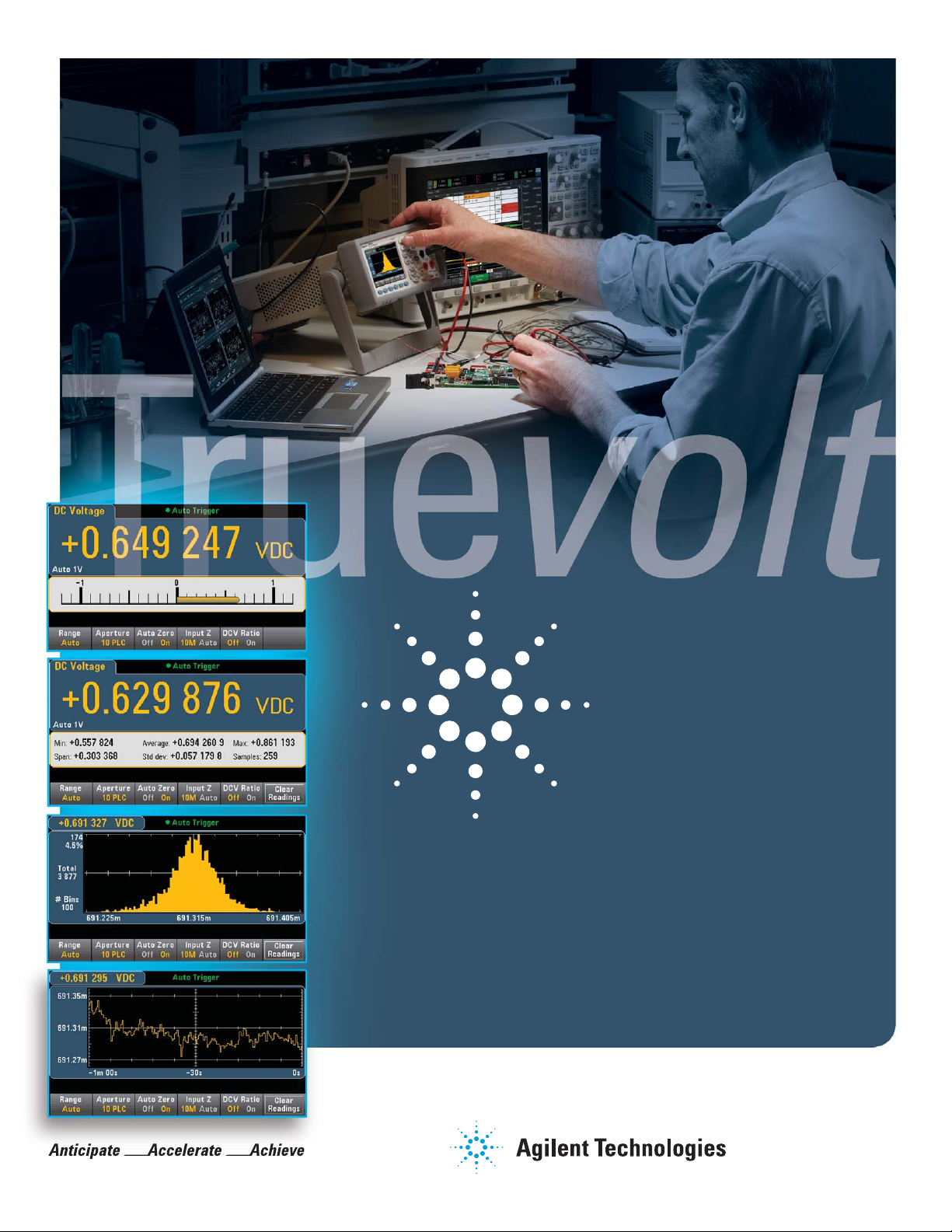
Display DMM results in ways you never have before
Easily display, save and document
your measurement results
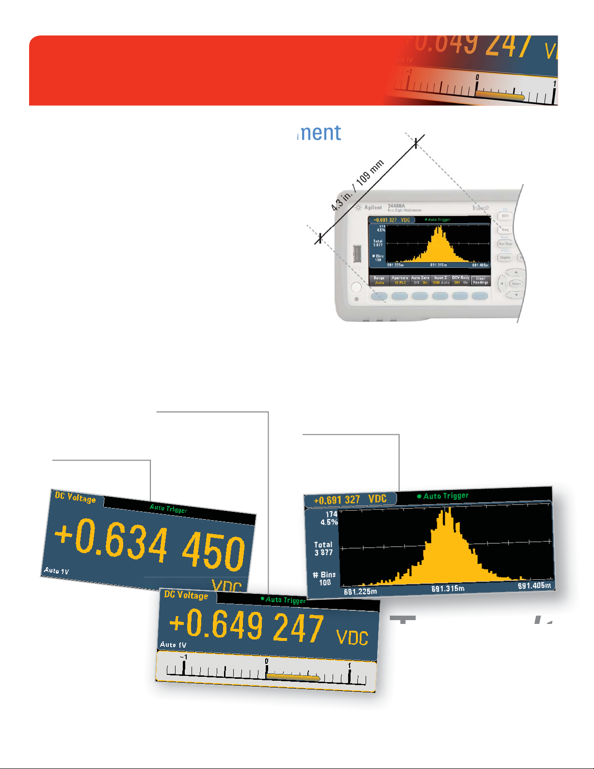
Easily set up and see your results and get actionable
information faster
• See your results clearly on a bright, 4.3-inch (109 mm), high-resolution, color
graphical display. Get answers faster using the intuitive, menu-driven interface.
If you have questions about a key or functionality, press and hold the key to
display built-in help on the subject.
• Customize display operation to meet your needs. Confi gure your preferences
and pull them up automatically at the next instrument start-up.
• Add customized labels to describe the instrument’s measurement your way.
• Get quick insight with graphical views of your measurement results: View
readings, long-term trends (34461A only) and measurement histograms
for a statistical view.
The bright, 4.3” high-resolution monitor is a prominent
feature of Agilent’s new Truevolt multimeter family.
Number mode provides
the traditional “digits” view
of measurements.
Bar meter mode provides the
number display along with an
analog meter to provide a visual
view of your measurements.
Histogram mode gives you a statistical
view of your measurements.
Truevolt
DISPLAY
2
Page 3
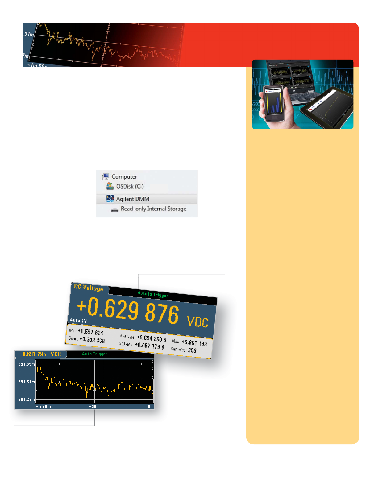
Display DMM results in ways you never have before
Save and document your DMM’s data to your PC
or mobile device using your preferred I/O:
• Control, capture and view your DMM’s data on your PC with a single click
using the Digital Multimeter Connectivity Utility via USB, GPIB, LAN,
or RS-232 (for older generation Agilent DMMs).
• Easily access the fi les on your
DMM using drag-and-drop
to transfer fi les via USB –
no software required.
• Choose the I/O that works best
for you: USB, LAN/LXI Core
(optional on 34460A), GPIB
(optional on 34460A & 34461A).
• Easily access the front-panel USB memory connector.
Test result screens allow you to show
measurement statistics on the display.
The free DMM connectivity
utility helps you get your
job done faster
Capture and export data to your PC with
drag and drop ease
Capture a digitized record, log measurements for
longer periods under PC control or upload data
captured directly from the instrument. Export data
from a single DMM, or multiple DMMs with time
alignment, to popular tools such as Microsoft
Excel, Microsoft Word and MATLAB. Simplify test
documentation and data analysis without the hassles
of programming.
Visualize multiple DMM outputs at once
Display single measurements, charts, or histograms
from a single instrument or up to four DMMs
simultaneously. See what’s happening on your
bench, all on one display—to spot correlated trends
you might otherwise miss.
Trend chart mode (34461A only)
displays your measurements
over time.
Simplify instrument confi guration
Instrument controls provide easy measurement setup
and instrument state management. Reduce set-up
times and quickly reconfi gure for new tests.
Speed up instrument discovery and connection for a broad range of Agilent DMMs
With one-click access to Agilent IO Libraries Suite,
connect to DMMs via USB, GPIB, LAN or RS-232.
Spend your valuable time testing your designs rather
than setting up, connecting, and troubleshooting
software.
Access and control tests on your DMM
remotely on your mobile device
With a companion app available, DMM Mobile
Utility, as a free download from the Apple App Store,
view and control your LAN-enabled instrument
wherever you go and receive email alerts when
problems occur. Remotely remedy problems on long
running tests to minimize project delays.
Download the DMM connectivity utility:
www.agilent.com/fi nd/DMMutilitysoftware
3
Page 4
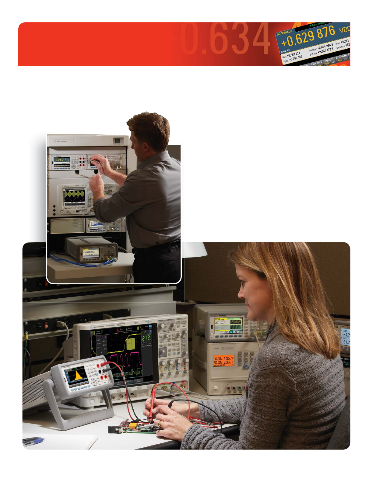
Measure with unquestioned Truevolt confi dence
Worry about the quality of your design, not the quality
of your measurements
In a rack or on a bench real-world signals are never fl at. They have some level
of AC signal riding on top from power line noise, other environmental noise, or
injected current from the meter itself. How well your meter deals with these
extraneous factors and eliminates them from the true measurement makes a big
difference to your accuracy. Behind the scenes, Agilent’s Truevolt technology
accounts for measurement errors created by these real-world factors so you can
be confi dent in your measurements and it is only available on Agilent DMMs.
Truevolt technology starts with an analog-to-digital converter that enables a
patented metrology-grade architecture. Using this architecture, Agilent delivers
a good balance of measurement resolution, linearity, accuracy, and speed at a
value price, all derived and guaranteed per ISO/IEC 17025 industry standards.
Truevolt
MEASUREMENT
4
Page 5
Measure with unquestioned Truevolt confi dence
lo
Peak value
RMS value
AC measurement
accuracy is
degraded when
signals have energy
contained in higher
frequencies than a
typical sine wave.
Crest factor: the ratio of the
peak value to the RMS value
of a waveform
Truevolt
60
50
403020
10
0
Brand A
Brand B
Brand C
Input
bias
current
too
noisy
to
measure
Truevolt
800
700
600
500
400
300
200
100
0
Brand A
Brand B
Brand C
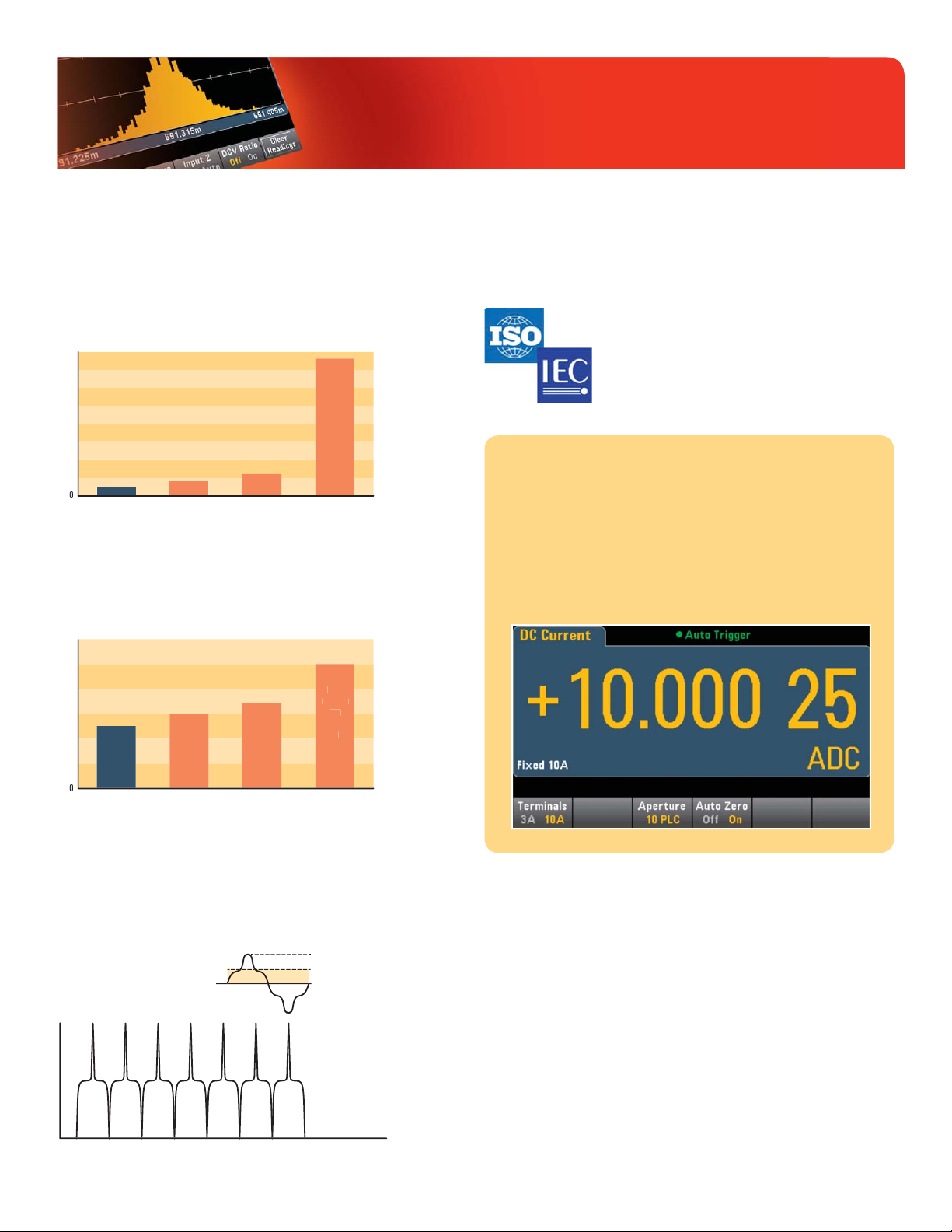
What Truevolt technology means to you:
You can measure your real-world signals,
not instrument error
Noise and injected current: Agilent Truevolt DMMs contribute less than
30% of the injected current than alternatives. Compared to some lower cost
alternatives, Truevolt DMMs offer almost 100% less noise.
Input bias current: Ideally, no current fl ows into the measurement terminals
of your DMM. In real measurement situations, there are always input currents
creating additional measurement errors. Truevolt DMMs take care of input bias
current. Some alternative DMMs offer 20% to infi nitely poorer performance
(some are too noisy to measure).
You can measure your real-world signals with confi dence
All Truevolt DMM specifi cations are tested and guaranteed for compliance
with ISO/IEC 17025 standards so you can prove the effectiveness
of your lab or production line’s quality management system.
of your
Many lower-cost DMMs in this class do not carry a guarantee
Many
of their measurement specifi cations.
You can take advantage of expanded
measurement functionality
Compared to the 34401A DMM, Truevolt DMMs offer expanded
current ranges from 100 µA to 10 A. We have also added a temperature measurement function (RTD/PT100, 5 kΩ thermistor).
Additionally, diode measurement capability has been expanded
to allow a larger full-scale voltage to be measured (5 V) to
enable the measurement of more diode types such as LEDs.
Digital AC rms measurements: For meters in this class, only Agilent uses
digital direct sampling techniques to make AC rms measurements. This results
in a true rms calculation technique that avoids the slower response of analog
RMS converters used in all other vendor’s 6½ digit DMMs. This allows for
crest factors up to 10 without additional error terms. This is a unique, patented
technique – only used by Agilent.
5
Page 6

Move to the next-generation
34401A DMM with 100% assurance
Migrate with confi dence: Everything you
depend on with the 34401A and more
Like most 34401A DMM owners, you rely on your
DMM and you trust the answers it gives you. Now,
with the Agilent Truevolt 34461A DMM, you can
get all of the advantages of the 34401A and more.
Now you can get faster answers and have even
more confi dence in your results.
The best news of all? You can migrate from the
34401A to the 34461A without a hassle. No need
to rewrite your software programs or spend hours
learning a brand-new, complicated interface.
Use your existing programs: The 34461A
DMM is the industry’s only 100% drop-in, SCPIcompatible replacement for the 34401A DMM.
Other DMMs may claim 34401A SCPI compatibility, but only a subset of SCPI commands are
implemented.
No long learning curve: The Truevolt DMMs
were designed by the same team that created the
34401A. The team kept 34401A measurements,
reliability and familiarity in mind as they created the
Truevolt family of DMMs. So you can use it without
spending hours learning how.
MIGRATION Q&A QUESTION ANSWER
Program
compatibility
Measurements Will I have the same performance so it
Cost Will it cost the same to buy, use,
Reliability My 34401A never breaks. Are the
Use Will we be able to use it easily? Quickly?
Will my existing programs still work
if I switch to the 34461A?
doesn’t affect the results on my line?
maintain, and repair?
Truevolt DMMs going to be as good?
YES
YES
YES (and potentially less since
the DMMs now include a 3-year
standard warranty)
YES That’s why we can offer
a 3-year standard warranty
YES
The 34461A represents everything you have known
and trusted with your Agilent DMM measurements
for decades – it just keeps getting stronger.
34461A: The industry’s only 100% drop-in,
SCPI-compatible replacement for the 34401A DMM
6
Truevolt
MIGRATION
Page 7

Move to the next-generation
34401A DMM with 100% assurance
WHICH MODEL IS RIGHT FOR YOU? 34460A 34461A 34401A
Resolution 6½ digits 6½ digits 6½ digits
Input terminals Front Front and rear Front and rear
1-year DCV accuracy
±(% of reading + % of range)
Measurement speed – 4½ digits 300 readings/s 1000 readings/s 1000 readings/s
Measurements
DCV, ACV, resistance,
frequency, period, continuity
Diode 5 V 5 V 1 V
Current 100 µA – 3 A 100 µA – 10 A 10 mA – 3 A
Temperature RTD/PT100, thermistor RTD/PT100, thermistor N/A
Internal memory 1,000 readings 10,000 readings 512 readings
Graphical display Number, histogram, bar meter Number, histogram, bar meter, trend Number
I/O connectivity USB (LAN, GPIB optional) USB, LAN (GPIB optional) GPIB, RS-232
OPTIONS 34460A 34461A 34401A
3446ACCU: Accessory kit for 34460A
Documentation CDs, test leads, USB cable
3446GPBU
GPIB user installable interface module
0.0075 + 0.0005 0.0035 + 0.0005 0.0035 + 0.0005
Same as 34401A baseline Same as 34401A baseline 34401A baseline
OPTIONAL INCLUDED STANDARD INCLUDED STANDARD
OPTIONAL OPTIONAL INCLUDED STANDARD
3446LANU
Enable rear panel LAN/LXI web interface,
external triggering for 34460A
3446SECU
Enable NISPOM and fi le security
OPTIONAL INCLUDED STANDARD N/A
OPTIONAL OPTIONAL N/A
7
Page 8

SPECIFICATIONS
34460A
34460A accuracy specifi cations: ± (% of reading + % of range)
These specifi cation are compliant to ISO/IEC 17025 for K = 2
1
Range 2/frequency 24 hour
DC voltage
100 mV 0.0040 + 0.0060 0.0070 + 0.0065 0.0090 + 0.0065 0.0115 + 0.0065 0.0005 + 0.0005
1 V 0.0030 + 0.0009 0.0060 + 0.0010 0.0080 + 0.0010 0.0105 + 0.0010 0.0005 + 0.0001
10 V 0.0025 + 0.0004 0.0050 + 0.0005 0.0075 + 0.0005 0.0100 + 0.0005 0.0005 + 0.0001
100 V 0.0030 + 0.0006 0.0065 + 0.0006 0.0085 + 0.0006 0.0110 + 0.0006 0.0005 + 0.0001
1000 V 0.0030 + 0.0006 0.0065 + 0.0010 0.0085 + 0.0010 0.0110 + 0.0010 0.0005 + 0.0001
True RMS AC voltage
100 mV, 1 V, 10 V, 100 V, and 750 V ranges
3 – 5 Hz 1.00 + 0.02 1.00 + 0.03 1.00 + 0.03 1.00 + 0.03 0.100 + 0.003
5 – 10 Hz 0.38 + 0.02 0.38 + 0.03 0.38 + 0.03 0.38 + 0.03 0.035 + 0.003
10 Hz – 20 kHz 0.07 + 0.02 0.08 + 0.03 0.09 + 0.03 0.10 + 0.03 0.005 + 0.003
20 – 50 kHz 0.13 + 0.04 0.14 + 0.05 0.15 + 0.05 0.16 + 0.05 0.011 + 0.005
50 – 100 kHz 0.58 + 0.08 0.63 + 0.08 0.63 + 0.08 0.63 + 0.08 0.060 + 0.008
100 – 300 kHz 4.00 + 0.50 4.00 + 0.50 4.00 + 0.50 4.00 + 0.50 0.200 + 0.020
Resistance
DC current Burden voltage
7
100 Ω 1 mA 0.0040 + 0.0060 0.011 + 0.007 0.014 + 0.007 0.017 + 0.007 0.0006 + 0.0005
1 kΩ 1 mA 0.0030 + 0.0008 0.011 + 0.001 0.014 + 0.001 0.017 + 0.001 0.0006 + 0.0001
10 kΩ 100 µA 0.0030 + 0.0005 0.011 + 0.001 0.014 + 0.001 0.017 + 0.001 0.0006 + 0.0001
100 kΩ 10 µA 0.0030 + 0.0005 0.011 + 0.001 0.014 + 0.001 0.017 + 0.001 0.0006 + 0.0001
1 MΩ 5 µA 0.0030 + 0.0010 0.011 + 0.001 0.014 + 0.001 0.017 + 0.001 0.0010 + 0.0002
10 MΩ 500 nA 0.015 + 0.001 0.020 + 0.001 0.040 + 0.001 0.060 + 0.001 0.0030 + 0.0004
100 MΩ 500 nA || 10 MΩ 0.300 + 0.010 0.800 + 0.010 0.800 + 0.010 0.800 + 0.010 0.1500 + 0.0002
100 µA <0.011 V 0.010 + 0.020 0.040 + 0.025 0.050 + 0.025 0.060 + 0.025 0.0020 + 0.0030
1 mA <0.11 V 0.007 + 0.006 0.030 + 0.006 0.050 + 0.006 0.060 + 0.006 0.0020 + 0.0005
10 mA <0.05 V 0.007 + 0.020 0.030 + 0.020 0.050 + 0.020 0.060 + 0.020 0.0020 + 0.0020
100 mA <0.5 V 0.010 + 0.004 0.030 + 0.005 0.050 + 0.005 0.060 + 0.005 0.0020 + 0.0005
1 A <0.7 V 0.050 + 0.006 0.080 + 0.010 0.100 + 0.010 0.120 + 0.010 0.0050 + 0.0010
3 A <2.0 V 0.180 + 0.020 0.200 + 0.020 0.200 + 0.020 0.230 + 0.020 0.0050 + 0.0020
2, 5, 6
Test current
T
CAL
± 1 °C
3
90 day
T
± 5 °C
CAL
1 year
T
± 5 °C
CAL
2 year
T
± 5 °C
CAL
Temperature
coeffi cient/°C
4
8
Page 9

SPECIFICATIONS
34460A
Range 2/frequency 24 hour
True RMS AC current
100 µA, 1 mA, 10 mA, and 100 mA ranges <0.011, <0.11, < 0.05, <0.5 V
3 Hz – 5 kHz 0.10 + 0.04 0.10 + 0.04 0.10 + 0.04 0.10 + 0.04 0.015 + 0.006
5 – 10 kHz
1 A range <0.7 V
3 Hz – 5 kHz 0.10 + 0.04 0.10 + 0.04 0.10 + 0.04 0.10 + 0.04 0.015 + 0.006
5 – 10 kHz
3 A range <2.0 V
3 Hz – 5 kHz 0.23 + 0.04 0.23 + 0.04 0.23 + 0.04 0.23 + 0.04 0.015 + 0.006
5 – 10 kHz
Continuity
1 kΩ 0.002 + 0.030 0.008 + 0.030 0.010 + 0.030 0.012 + 0.030 0.0010 + 0.0020
Diode test
5 V 0.002 + 0.030 0.008 + 0.030 0.010 + 0.030 0.012 + 0.030 0.0010 + 0.0020
DC ratio
Temperature
PT100 (DIN/ IEC 751) Probe accuracy + 0.05 °C
5 kΩ thermistor Probe accuracy + 0.1 °C
Frequency: specifi cation ± (% of reading)
100 mV, 1 V, 10 V, 100 V, and 750 V ranges
3 – 10 Hz 0.100 0.100 0.100 0.100 0.0002
10 – 100 Hz 0.030 0.030 0.030 0.035 0.0002
100 Hz – 1 kHz 0.003 0.010 0.012 0.017 0.0002
1 – 300 kHz 0.002 0.008 0.012 0.017 0.0002
Square wave
Additional gate time errors ± ( % of reading )
Frequency 1 second 0.1 second 0.01 second
3 – 40 Hz 0 0.200 0.200
40 – 100 Hz 0 0.060 0.200
100 Hz – 1 kHz 0 0.020 0.200
1 – 300 kHz 0 0.004 0.030
Square wave
9
9
9
10
11
2, 6, 8
12
16
16
Burden voltage
13, 14
15
13, 14
3
T
± 1 °C
CAL
0.10 + 0.04 0.10 + 0.04 0.10 + 0.04 0.10 + 0.04 0.030 + 0.006
0.10 + 0.04 0.10 + 0.04 0.10 + 0.04 0.10 + 0.04 0.030 + 0.006
0.23 + 0.04 0.23 + 0.04 0.23 + 0.04 0.23 + 0.04 0.030 + 0.006
0.001 0.008 0.012 0.017 0.0002
000
90 day
T
± 5 °C
CAL
(normalized input accuracy) + (normalized reference accuracy)
1 year
T
± 5 °C
CAL
2 year
T
± 5 °C
CAL
Temperature
coeffi cient/°C
4
1. For DC: Specifi cations are for 60-minute warm-up, aperture of 10 or 100 NPLC,
and auto zero on.
For AC: Specifi cations are for 60-minute warm-up, slow AC fi lter, sine wave.
2. 20% overrange on all ranges, except 1000 DCV, 750 ACV, 3 A AC, and diode test.
3. Relative to calibration standards.
4. Add this for each °C outside T
5. Specifi cations are for sine wave input > 0.3% of range and > 1 mVrms.
750 ACV range limited to 8 x 10⁷ Volt–Hz.
6. Low-frequency performance: three fi lter settings are available: 3 Hz, 20 Hz, 200 Hz.
Frequencies greater than these fi lter settings are specifi ed with no additional errors.
7. Specifi cations are for 4–wire ohms function or 2–wire ohms using math null for offset. Without
math null, add 0.2 Ω additional error in 2-wire ohms function.
8. Specifi cations are for sinewave input >1% of range and > 10 µA AC.
9. AC current specifi cations > 5 kHz are typical.
CAL
± 5 °C.
10. Specifi cations are for the voltage measured at the input terminals. The 1 mA test current
is typical. Variation in the current source will create some variation in the voltage drop across
a diode junction.
11. These specifi cations are for typical performance.
12. Actual measurement range and probe errors will be limited by the selected probe.
Probe accuracy adder includes all measurement and ITS-90 temperature conversion errors
PT100 Ro settable to 100 Ω ± 5 Ω to remove the initial probe error.
13. Specifi cations are for 60-minute warm-up and sine wave input unless stated otherwise.
Specifi cations are for 1-second gate time (7 digits).
14. Applies to sine and square inputs ≥ 100 mV.
For 10 mV to < 100 mV inputs, multiply % of reading error x10.
15. Amplitude 10% –120% of range and less than 750 ACV.
16. Square wave input specifi ed for 10 Hz – 300 kHz.
9
Page 10

SPECIFICATIONS
34461A
34461A accuracy specifi cations: ± (% of reading + % of range)
These specifi cation are compliant to ISO/IEC 17025 for K = 2
1
Range 2/frequency 24 hour
DC voltage
100 mV 0.0030 + 0.0030 0.0040 + 0.0035 0.0050 + 0.0035 0.0065 + 0.0035 0.0005 + 0.0005
1 V 0.0020 + 0.0006 0.0030 + 0.0007 0.0040 + 0.0007 0.0055 + 0.0007 0.0005 + 0.0001
10 V 0.0015 + 0.0004 0.0020 + 0.0005 0.0035 + 0.0005 0.0050 + 0.0005 0.0005 + 0.0001
100 V 0.0020 + 0.0006 0.0035 + 0.0006 0.0045 + 0.0006 0.0060 + 0.0006 0.0005 + 0.0001
1000 V 0.0020 + 0.0006 0.0035 + 0.0010 0.0045 + 0.0010 0.0060 + 0.0010 0.0005 + 0.0001
True RMS AC voltage
100 mV, 1 V, 10 V, 100 V, and 750 V ranges
3 – 5 Hz 1.00 + 0.02 1.00 + 0.03 1.00 + 0.03 1.00 + 0.03 0.100 + 0.003
5 – 10 Hz 0.35 + 0.02 0.35 + 0.03 0.35 + 0.03 0.35 + 0.03 0.035 + 0.003
10 Hz – 20 kHz 0.04 + 0.02 0.05 + 0.03 0.06 + 0.03 0.07 + 0.03 0.005 + 0.003
20 – 50 kHz 0.10 + 0.04 0.11 + 0.05 0.12 + 0.05 0.13 + 0.05 0.011 + 0.005
50 – 100 kHz 0.55 + 0.08 0.60 + 0.08 0.60 + 0.08 0.60 + 0.08 0.060 + 0.008
100 – 300 kHz 4.00 + 0.50 4.00 + 0.50 4.00 + 0.50 4.00 + 0.50 0.200 + 0.020
Resistance
DC current Burden voltage
7
100 Ω 1 mA 0.0030 + 0.0030 0.008 + 0.004 0.010 + 0.004 0.012 + 0.004 0.0006 + 0.0005
1 kΩ 1 mA 0.0020 + 0.0005 0.008 + 0.001 0.010 + 0.001 0.012 + 0.001 0.0006 + 0.0001
10 kΩ 100 µA 0.0020 + 0.0005 0.008 + 0.001 0.010 + 0.001 0.012 + 0.001 0.0006 + 0.0001
100 kΩ 10 µA 0.0020 + 0.0005 0.008 + 0.001 0.010 + 0.001 0.012 + 0.001 0.0006 + 0.0001
1 MΩ 5 µA 0.002 + 0.001 0.008 + 0.001 0.010 + 0.001 0.012 + 0.001 0.0010 + 0.0002
10 MΩ 500 nA 0.015 + 0.001 0.020 + 0.001 0.040 + 0.001 0.060 + 0.001 0.0030 + 0.0004
100 MΩ 500 nA || 10 MΩ 0.300 + 0.010 0.800 + 0.010 0.800 + 0.010 0.800 + 0.010 0.1500 + 0.0002
100 µA <0.011 V 0.010 + 0.020 0.040 + 0.025 0.050 + 0.025 0.060 + 0.025 0.0020 + 0.0030
1 mA <0.11 V 0.007 + 0.006 0.030 + 0.006 0.050 + 0.006 0.060 + 0.006 0.0020 + 0.0005
10 mA <0.05 V 0.007 + 0.020 0.030 + 0.020 0.050 + 0.020 0.060 + 0.020 0.0020 + 0.0020
100 mA <0.5 V 0.010 + 0.004 0.030 + 0.005 0.050 + 0.005 0.060 + 0.005 0.0020 + 0.0005
1 A <0.7 V 0.050 + 0.006 0.080 + 0.010 0.100 + 0.010 0.120 + 0.010 0.0050 + 0.0010
3 A <2.0 V 0.180 + 0.020 0.200 + 0.020 0.200 + 0.020 0.230 + 0.020 0.0050 + 0.0020
10 A <0.5 V 0.050 + 0.010 0.120 + 0.010 0.120 + 0.010 0.150 + 0.010 0.0050 + 0.0010
2, 5, 6
Test current
T
CAL
± 1 °C
3
90 day
T
± 5 °C
CAL
1 year
T
± 5 °C
CAL
2 year
T
± 5 °C
CAL
Temperature
coeffi cient/°C
4
10
Page 11

SPECIFICATIONS
34461A
3
Range 2/frequency
True RMS AC current
100 µA, 1 mA, 10 mA, and 100 mA ranges <0.011, <0.11, <0.05, <0.5 V
3 Hz – 5 kHz 0.10 + 0.04 0.10 + 0.04 0.10 + 0.04 0.10 + 0.04 0.015 + 0.006
5 – 10 kHz
1 A range <0.7 V
3 Hz – 5 kHz 0.10 + 0.04 0.10 + 0.04 0.10 + 0.04 0.10 + 0.04 0.015 + 0.006
5 – 10 kHz
3 A range <2.0 V
3 Hz – 5 kHz 0.23 + 0.04 0.23 + 0.04 0.23 + 0.04 0.23 + 0.04 0.015 + 0.006
5 – 10 kHz
10 A range <0.5 V
3 Hz – 5 kHz 0.15 + 0.04 0.15 + 0.04 0.15 + 0.04 0.15 + 0.04 0.015 + 0.006
5 – 10 kHz
Continuity
1 kΩ 0.002 + 0.030 0.008 + 0.030 0.010 + 0.030 0.012 + 0.030 0.0010 + 0.0020
Diode test
5 V 0.002 + 0.030 0.008 + 0.030 0.010 + 0.030 0.012 + 0.030 0.0010 + 0.0020
DC ratio
Temperature
PT100 (DIN/ IEC 751) Probe accuracy + 0.05 °C
5 kΩ thermistor Probe accuracy + 0.1 °C
Frequency: specifi cation ± (% of reading)
100 mV, 1 V, 10 V, 100 V, and 750 V ranges
3 – 10 Hz 0.100 0.100 0.100 0.100 0.0002
10 – 100 Hz 0.030 0.030 0.030 0.035 0.0002
100 Hz – 1 kHz 0.003 0.008 0.010 0.015 0.0002
1 – 300 kHz 0.002 0.006 0.010 0.015 0.0002
Square wave
Additional gate time errors ± ( % of reading )
Frequency 1 second 0.1 second 0.01 second
3 – 40 Hz 0 0.200 0.200
40 – 100 Hz 0 0.060 0.200
100 Hz – 1 kHz 0 0.020 0.200
1 – 300 kHz 0 0.004 0.030
Square wave
9
9
9
9
10
11
2, 6, 8
12
16
16
Burden voltage
13, 14
15
13, 14
24 hour
T
± 1 °C
CAL
0.10 + 0.04 0.10 + 0.04 0.10 + 0.04 0.10 + 0.04 0.030 + 0.006
0.10 + 0.04 0.10 + 0.04 0.10 + 0.04 0.10 + 0.04 0.030 + 0.006
0.23 + 0.04 0.23 + 0.04 0.23 + 0.04 0.23 + 0.04 0.030 + 0.006
0.15 + 0.04 0.15 + 0.04 0.15 + 0.04 0.15 + 0.04 0.030 + 0.006
0.001 0.006 0.010 0.015 0.0002
000
90 day
T
± 5 °C
CAL
(normalized input accuracy) + (normalized reference accuracy)
1 year
T
± 5 °C
CAL
2 year
T
± 5 °C
CAL
Temperature
coeffi cient/°C
4
1. Specifi cations are for 60-minute warm-up, integration setting of 10 or 100 NPLC,
and auto-zero on. Specifi cations are for 60-minute warm-up, slow AC fi lter, sinewave.
2. 20% over range on all ranges, except 1000 DCV, 750 ACV, 10 A DC, 3 A AC, 10 A AC,
and diode test.
3. Relative to calibration standards.
4. Add this for each °C outside TCAL ± 5 °C.
5. Specifi cations are for sinewave input >0.3% of range and > 1 mVrms.
750 ACV range limited to 8 x 10 7 Volt–Hz.
6. Low-frequency performance: three fi lter settings are available: 3 Hz, 20 Hz, 200 Hz.
Frequencies greater than these fi lter settings are specifi ed with no additional errors.
7. Specifi cations are for 4-wire ohms function or 2-wire ohms using math null for offset. Without
math null, add 0.2 Ω additional error in 2-wire ohms function.
8. Specifi cations are for sinewave input > 1% of range and > 10 µA AC. The 10 A range is only
available on a separate front-panel connector.
9. AC current specifi cations > 5 kHz are typical.
10. Specifi cations are for the voltage measured at the input terminals. The 1 mA test current
is typical. Variation in the current source will create some variation in the voltage drop
across a diode junction.
11. These specifi cations are for typical performance.
12. Actual measurement range and probe errors will be limited by the selected probe.
Probe accuracy adder includes all measurement and ITS-90 temperature conversion errors.
PT100 Ro settable to 100 Ω ±5 Ω to remove the initial probe error.
13. Specifi cations are for 60-minute warm-up and sine wave input unless stated otherwise.
Specifi cations are for 1-second gate time (7-digits).
14. Applies to sine and square inputs ≥ 100 mV.
For 10 mV to < 100 mV inputs, multiply % of reading error x10.
15. Amplitude 10%–120% of range and less than 750 ACV.
16. Square wave input specifi ed for 10 Hz – 300 kHz.
11
Page 12

MEASUREMENT CHARACTERISTICS
34460A/34461A
Measurement characteristics
DC voltage
Measurement method: Agilent patented continuously integrating
A/D linearity: 0.0002% of reading + 0.0001% of range
Input resistance:
0.1 V, 1 V, 10 V range
100 V, 1000 V range
Input bias current: <30 pA at 25 °C
Input terminals: Copper alloy
Input protection: 1000 V on all ranges
True RMS AC voltage
Measurement type: AC–coupled True RMS.
Measurement method: Digital sampling with anti-alias fi lter
Maximum input: 400 DCV, 1100 Vpeak
Input impedance: 1 MΩ ±1%, in parallel with <100 pF
Input protection: 750 Vrms all ranges
DC and True RMS AC current
AC measurement type: Directly coupled to the fuse and shunt.
AC measurement method: Digital sampling with anti-alias fi lter
Input protection 3 A: Externally accessible 3.15 A, 500 V fuse
Input protection 10 A:
(34461A only)
AC crest factor and peak input
Crest factor: 10:1 maximum crest factor, (3:1 at full-scale). Measurement
Peak input: 300% of range or maximum input
Overload ranging : Will select higher range if peak input overload is detected
Resistance
Measurement method: Selectable 4-wire or 2-wire ohms.
Maximum lead resistance
(4-wire ohms):
Input protection: 1000 V on all ranges
Continuity/diode test
Response time: 300 samples/s with audible tone
Continuity threshold: Fixed at 10 Ω
DC ratio
Measurement method: Input HI-LO/reference (sense) HI-LO
Input HI-LO: 100 mV to 1000 V ranges
Reference (sense) HI-Input LO: 100 mV to 10 V ranges (autoranged)
Input to reference (sense): HI and LO reference (sense) terminals reference
Temperature
PT100 platinum RTD sensor, α= 0.00385Ω/Ω/°C; DIN/IEC 751.
Measurement conversions limited to -200 to 600 °C.
5-kΩ thermistor β= 3891; YSI 44007 or equivalent.
Measurement conversions limited to -80 to 150 °C.
multi-slope IV A/D converter
Selectable 10 MΩ or >10 GΩ
10 MΩ ± 1%
Measures the AC component of the input.
AC True RMS measurement (measures the AC component only).
(Replacement part number 2110-1547 3.15 A external fuse)
Internal 11-A, 1000-V fuse
(Replacement part number 2110-1402 11 A external fuse)
Internal 11-A, 1000-V fuse
(Replacement part number 2110-1402 11 A external fuse)
bandwidth limited to 300 kHz for signal plus harmonics.
during auto range. Overload is reported in manual ranging.
Current source referenced to LO input.
10% of range per lead for 100 Ω, 1 kΩ ranges.
1 kΩ per lead on all other ranges.
to LO input <12 V
Measurement noise rejection
60 Hz (50 Hz ) for 1-kΩ LO lead unbalance ( ± 500 V peak maximum)
DC CMRR: 140 dB
AC CMRR: 70 dB
Integration time Normal mode rejection
100 PLC/1.67 s (2 s) 60 dB
10 PLC/167 ms (200 ms) 60 dB
1 PLC/16.7 ms (20 ms) 60 dB
0.2 PLC/3 ms (3 ms) 0 dB
0.02 PLC/400 µs (400 µs) 0 dB
Frequency and period
Measurement method: Reciprocal-counting technique.
Voltage ranges: 100 mVrms full scale to 750 Vrms. Auto or manual ranging.
Gate time: 10 ms, 100 ms, or 1 s
Measurement considerations All frequency counters are susceptible to error when
Autozero OFF operation
Following instrument warm–up at a stable ambient temperature ±1 °C and <10 minutes.
Add 0.0002% of range + 5 µV for DCV or + 5 mΩ for resistance.
Measurement settling considerations
ACV, ACI, Frequency, Period
Default delays are selected to give fi rst reading right for most measurements. Errors will
occur when attempting to measure the frequency or period of an input following a DC
offset voltage change. The input blocking RC time constant must be allowed to fully settle
(up to 1 second) before the most accurate measurements are possible.
Applying >300 V ACrms or >1 Arms will cause self-heating in signal-conditioning components. These errors are included in the instrument specifi cations. Internal temperature
changes due to self-heating may cause additional error on other functions or ranges.
The additional error will generally dissipate within a few minutes.
DCV, DCI, Resistance
Applying >1 A DC will cause self-heating in signal-conditioning components. These errors
are included in the instrument specifi cations. Internal temperature changes due to selfheating may cause additional error on other functions or ranges. The additional error will
generally dissipate within a few minutes.
Reading settling times are affected by source impedance, cable dielectric characteristics,
and input signal changes. Agilent recommends the use of PTFE or other high-impedance,
low-dielectric absorption wire insulation for these measurements.
1. For power-line frequency ± 0.1%
2. For power-line frequency ± 1%, the NMR is 40 dB
For ± 3%, use 30 dB
2
1
2
2
Measurement is AC-coupled using AC measurement functions.
measuring low-voltage, low-frequency signals. Shielding
inputs from external noise pickup is critical for minimizing
measurement errors.
12
Page 13

OPERATING CHARACTERISTICS
34460A/34461A
Performance versus measurement speed
For DC voltage, DC current, and resistance
Integration time Digits Readings/s Digits Readings/s Additional noise error
100 PLC/1.67 s (2 s) 6½ 0.6 (0.5) 6½ 0.6 (0.5) 0% of range
10 PLC/167 ms (200 ms) 6½ 6 (5) 6½ 6 (5) 0% of range
1 PLC/16.7 ms (20 ms) 5½ 60 (50) 5½ 60 (50) 0.001% of range
0.2 PLC/3 ms (3 ms) 5½ 100 5½ 300 0.001% of range
0.02 PLC/400 µs (400 µs) 3½ 300 4½ 1000 0.01% of range
AC voltage, AC current
Frequency, period
1. Reading speeds for 60 Hz and 50 Hz operation, autozero off, fi xed range.
2. Add 20 µV for DCV and 20 mΩ for resistance.
Add 0.2 µA for DC current + 10x the above range error for the 10 mA range.
3. Maximum reading rates for 0.01% of AC step additional error.
Additional settling delay required when input DC level varies.
4. For external trigger or remote operation using default settling delay (Delay Auto).
5. Maximum useful limit with default settling delays defeated.
3, 4
1
34460A 34461A
Digits ACV ACI AC fi lter
6½ .4/s .6/s Slow
6½ 1.6/s 4/s Medium
6½ 40/s 40/s Fast
6½ 50/s
Aperture Digits Readings
1 Second 7 1
0.1 Second 6 10
0.01 Second 5 80
5
50/s
5
Fast
2
2
System Speeds (average)
DC voltage, DC current, resistance
Autorange time
Maximum internal trigger rate 300/s 1000/s
Maximum external trigger rate 300/s 1000/s
ASCII readings to bus 300/s 1000/s
Single reading transaction rate
AC voltage, AC current
Autorange time
Maximum internal trigger rate 50/s 50/s
Maximum external trigger rate 50/s 50/s
ASCII readings to bus 50/s 50/s
Single reading transaction rate
Frequency, period
Autorange time
Maximum internal trigger rate 80/s 80/s
Maximum external trigger rate 80/s 80/s
ASCII readings to bus 80/s 80/s
Single reading transaction rate
1. 0.02 NPLC, delay 0, autozero off, math off, and display off.
2. These rates apply to all I/O interfaces.
3. Time to automatically change one range and be ready for new measurement, ≤10 V, ≤10 MΩ.
4. Includes measurement and IO time (assumes connection via SOCKETS. VXI-11 connections may be slower).
5. Fast AC fi lter, delay 0, math off, and display off.
6. 10-ms aperture, fast AC fi lter, delay 0, math off, and display off.
3
5
3
6
3
1, 2
4
4
4
34460A 34461A
<30 ms <30 ms
50/s 150/s
10/s 10/s
50/s 50/s
10/s 10/s
50/s 50/s
5
34460A DMM rear panel with GPIB option installed.
34461A DMM rear panel with GPIB option installed.
13
Page 14
GENERAL CHARACTERISTICS
34460A/34461A
General characteristics
Line power
Power supply: 100/120 (127)/ 220 (230)/240 VAC ± 10%, CAT II
Power line frequency: 50/60/400 Hz ± 10%
Power consumption: 25 VA
Environment
Operating environment: Full accuracy for 0 to 55 °C
Operating altitude: Up to 3000 m
Storage temperature: -40 to 70 °C
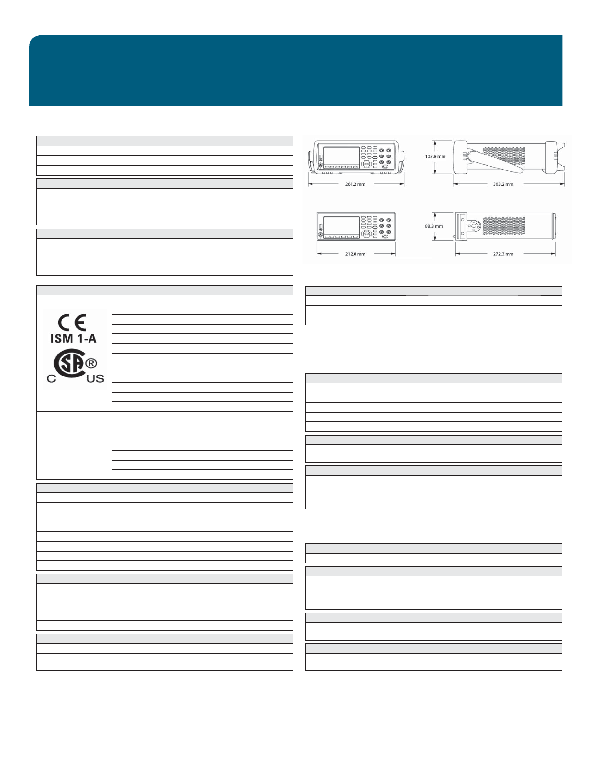
Mechanical
Rack dimensions: (W x H x D): 212.8 mm x 88.3 mm x 272.3 mm
Bench dimensions: (W x H x D): 261.2 mm x 103.8 mm x 303.2 mm
Weight: 34460A: 3.68 kg (8.1 lb)
Full accuracy to 80% R.H. at 40 °C non–condensing
34461A: 3.76 kg (8.3 lb)
Regulatory
Safety EN 61010-1:2010 (3rd Edition)
ANSI/ISA-61010-1 (82.02.01) Third Edition
ANSI/UL 61010-1 Third Edition
CAN/CSA-C22.2 No. 61010-1 Third Edition
EN 61010-2-030:2010 (1st Edition)
ANSI/ISA-61010-2-030 (82.02.03) First Edition
ANSI/UL 61010-2-030 First Edition
CAN/CSA-C22.2 No. 61010-2-030 First Edition
Refer to Declaration of Conformity for current revisions
Measurement Category II to 300 V
Other non MAINS circuits to 1000 Vpk
Pollution Degree 2
EMC IEC 61326
EN 61326
CISPR
ICES-001
AS/NZS 2064.1
Refer to Declaration of Conformity for current revisions
Acoustic noise (nominal) 45 dBA
Triggering conditions
External input Low–power TTL compatible input programmable edge triggered
Delay: <1 µs
Jitter: <1 µs
Minimum pulse width: 1 µs
Maximum rate: Up to 1 kHz (34461A), up to 300 Hz (34460A)
Voltmeter complete output 3.3 V logic output
Polarity: Programmable edge pulse
Pulse width: Approximately 2 µs
Computer interfaces
LXI (rev 1.4) 10/100Base-T Ethernet (Sockets, VXI-11 protocol,
Web user interface) (Optional on 34460A)
USB USB 2.0 (USB-TMC488 & MTP protocol)
GPIB Optional GPIB IEEE-488
Language SCPI-1999, IEEE-488.2, 34401A compatible
Front-panel USB host port
Supports USB 2.0 high-speed mass storage (MSC) class devices
Capability: import/export instrument confi guration fi les, save volatile readings
and screen captures
System speeds (averages)
Benchmark GPIB USB 2.0 VXI-11 Sockets
Function change
Range change
1. Rate to change from 2-wire resistance to any other function
2. Rate to change from one range to the next higher range, ≤ 10 V, ≤ 10 MΩ
Triggering and memory
Samples per trigger 1 to 1,000,000
Trigger delay 0 to 3600 sec (~1 µs step size)
External trigger delay <10 µs
External trigger jitter <1 µs (DC fi xed range)
Volatile reading memory 10,000 (34461A), 1,000 (34460A)
Probe hold
Sensitivity fi xed at 1% of reading
Capture and navigate stable list of readings
Internal fl ash fi le system
80 MB total capacity
Save reading memory to non-volatile memory in CSV format
Store and recall user-defi ned states, power-off state,
Save screen captures in BMP or PNG formats
1. Power-off state only when power-down is initiated via front-panel power switch.
Math functions
Per function null, min/max/avg/Sdev, dB, dBm, span, count, limit test, histogram
Display
4.3” color TFT WQVGA (480x272) with LED backlight
Supports: basic number, bar chart, trend chart (34461A only), histogram views
User-defi ned power-on message, display label, and selectable screen colors
Integrated, context-sensitive system help through press-and-hold buttons
Real-time clock/calendar
Set and read, year, month, day, hour, minute, seconds (Note: seconds not settable)
Battery CR-2032 coin-type, replaceable, >10-year life (typ)
Software available
IO Libraries: www.agilent.com/fi nd/IOLibraries
DMM Connectivity Utility software: www.agilent.com/fi nd/DMMutilitysoftware
1
2
50/s 50/s 50/s 50/s
100/s 100/s 100/s 100/s
1
and preference fi les
14
Page 15

OPTIONS & ACCESSORIES
34460A/34461A
Options
34460A Digital multimeter, 6½ digit, basic Truevolt DMM
LAN Rear panel LAN/LXI Web interface, external triggering for 34460A
SEC Enable NISPOM and fi le security for Truevolt Series DMMs
Z54 Certifi cate of calibration – ANSI/NCSL Z540.3-2006, printed
GPB GPIB user-installable interface module for Truevolt Series DMMs
ACC Accessory kit for 34460A – documentation CDs, test leads, USB cable
34461A Digital multimeter, 6½ digit, 34401A replacement, Truevolt DMM
SEC Enable NISPOM and fi le security for Truevolt Series DMMs
Z54 Certifi cate of calibration – ANSI/NCSL Z540.3-2006, printed
GPB GPIB user-installable interface module for Truevolt Series DMMs
Accessories
Accessories included
34460A: Power cord
34461A: 34138A test lead set with probes, fi ne tip probes, SMT grabbers
Accessories available
11059A Kelvin probe set
11060A Surface-mount device probe
11062A Kelvin clip set
34131A Transit case
34133A Precision electronic test leads
34134A DC-coupled current probe
34136A High-voltage probe
34138A Test lead set
34162A Accessory pouch
34171B Input terminal block
34172B Calibration short
34308A Thermistor kit
34330A 30-A current shunt
E2308A Thermistor temperature probe
Y1133A Low-thermal external digital multimeter scanning kit
Calibration certifi cate
and mini grabber attachments
Power cord
Documentation CD
IO Libraries CD
USB cable
Calibration certifi cate
Standalone product numbers
Ordered as standalone to be installed by the distributor or customer
3446LANU Upgrade:
Rear panel LAN/LXI Web interface, external triggering for 34460A
3446SECU Upgrade:
Enable NISPOM and fi le security for Truevolt Series DMMs
3446GPBU Upgrade:
GPIB user-installable interface module for Truevolt Series DMMs
3446ACCU Accessory kit for 34460A:
Documentation CDs, test leads, USB cable
Rack mount kits
34190A Rackmount kit:
Use for mounting one 2U instrument by itself, without another instrument
laterally next to it. Includes one rack fl ange and one combination
rack fl ange-fi ller panel.
34191A 2U dual fl ange kit:
Use for mounting two 2U instruments side-by-side.
Includes two standard rack fl anges.
Note: Mounting two instruments side-by-side will require the
34194A dual-lock link kit and a shelf for the instruments to sit on.
34194A Dual lock link kit:
For side-by-side combinations of instruments and includes links
for instruments of different depths.
Standard 3-Year Warranty
Defi nitions
Specifi cation (spec)
The warranted performance of a calibrated instrument that has been stored for a
minimum of 2 hours within the operating temperature range of 0 – 55 °C and after a
60-minute warm up period. All specifi cations include measurement uncertainty and
were created in compliance with ISO-17025 methods. Data published in this document
are specifi cations (spec) only where specifi cally indicated.
Typical (typ)
The characteristic performance, which 80% or more of manufactured instruments will
meet. This data is not warranted, does not include measurement uncertainty, and is
valid only at room temperature (approximately 23 °C).
Nominal (nom)
The mean or average characteristic performance, or the value of an attribute that is
determined by design such as a connector type, physical dimension, or operating speed.
This data is not warranted and is measured at room temperature (approximately 23 °C).
Measured (meas)
An attribute measured during development for purposes of communicating the expected
performance. This data is not warranted and is measured at room temperature (approximately 23 °C).
T
CAL
The temperature at which the instrument was calibrated.
15
Page 16

www.agilent.com
s
www.agilent.com/find/truevolt
myAgilent
myAgilent
www.agilent.com/find/myagilent
A personalized view into the information most
relevant to you.
www.axiestandard.org
AdvancedTCA
®
Extensions for Instrumentation
and Test (AXIe) is an open standard that
extends the AdvancedTCA for general purpose
and semiconductor test. Agilent is a founding
member of the AXIe consortium.
www.lxistandard.org
LAN eXtensions for Instruments puts the power
of Ethernet and the Web inside your test systems. Agilent is a founding member of the LXI
consortium.
www.pxisa.org
PCI eXtensions for Instrumentation (PXI) modular
instrumentation delivers a rugged, PC-based
high-performance measurement and automation
system.
Agilent Channel Partners
www.agilent.com/find/channelpartners
Get the best of both worlds: Agilent’s measurement
expertise and product breadth, combined with
channel partner convenience.
Three-Year Warranty
www.agilent.com/find/ThreeYearWarranty
Agilent’s combination of product reliability and threeyear warranty coverage is another way we help you
achieve your business goals: increased confidence
in uptime, reduced cost of ownership and greater
convenience.
Agilent Advantage Services
www.agilent.com/find/AdvantageServices
Accurate measurements throughout the life of your
instruments.
Agilent Electronic Measurement Group
DEKRA Certified
ISO 9001:2008
Quality Management SystemQuality Management Sy
www.agilent.com/quality
For more information on Agilent Technologies’
products, applications or services, please contact your
local Agilent office. The complete list is available at:
www.agilent.com/find/contactus
America
Canada (877) 894 4414
Brazil (11) 4197 3600
Mexico 01800 5064 800
United States (800) 829 4444
Asia Pacifi c
Australia 1 800 629 485
China 800 810 0189
Hong Kong 800 938 693
India 1 800 112 929
Japan 0120 (421) 345
Korea 080 769 0800
Malaysia 1 800 888 848
Singapore 1 800 375 8100
Taiwan 0800 047 866
Other AP Countries (65) 375 8100
Europe & Middle East
Belgium 32 (0) 2 404 93 40
Denmark 45 45 80 12 15
Finland 358 (0) 10 855 2100
France 0825 010 700*
*0.125 €/minute
Germany 49 (0) 7031 464 6333
Ireland 1890 924 204
Israel 972-3-9288-504/544
Italy 39 02 92 60 8484
Netherlands 31 (0) 20 547 2111
Spain 34 (91) 631 3300
Sweden 0200-88 22 55
United Kingdom 44 (0) 118 927 6201
For other unlisted countries:
www.agilent.com/find/contactus
(BP-3-1-13)
Product specifications and descriptions in this document
subject to change without notice.
© Agilent Technologies, Inc. 2013
Published in USA, April 5, 2013
5991-1983EN
 Loading...