

Page 1
FREQUENCY, FUNCTION & WAVEFORM SYNTHESIZERS
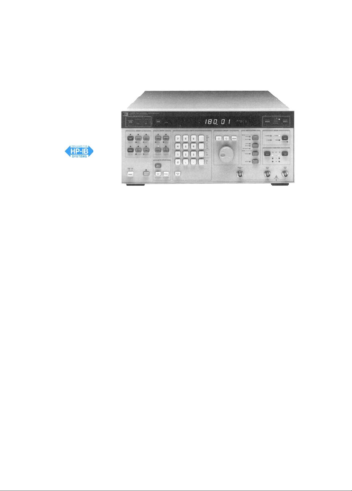
Two-Channel Synthesizer, DC to 13 MHz
Model 3326A
HP 3326A
The HP 3326A Two-Channel Synthesizer combines two independent synthesizers, flexible modulation, and control circuitry into a single, powerful package. This single instrument can provide precise
phase offset, two-tone sweep, fast frequency switching, internal modulation, and pulse signals for bench or systems use.
Complete Two-Phase Solution
The HP 3326A can provide two signals whose phase is adjustable
and calibrated anywhere in its 13 MHz frequency range without an
external phasemeter.
Self-calibration can be performed internally or externally and
yields accuracy of ±0.2 degrees below 100 kHz. Phase can be set with
0.01 degree resolution at all frequencies. Using its unique phase-calibration circuitry, calibrated multi-phase signals are easily achieved
with two or more HP 3326As.
Powerful Two-Tone Capability
The HP 3326A is the single-source answer for producing a wide
variety of broadband two-tone signals. It's two channels can be offset
up to ±100 kHz, either in the CW mode or while sweeping.
Channel amplitudes and functions (sine or square) can be selected
independently and provided from separate outputs or through the
built-in signal combiner. Low sinewave distortion (harmonics are at
least -70 dBc below 100 kHz) makes low-distortion intermodulation
measurements a simple task.
Versatile ATE Source
With two complete synthesizers in a single instrument, rack space
and power are conserved. Features like internal amplitude and phase
modulation, two-tone, and pulse modes allow this one instrument to
do the job of several sources.
All functions, modes, and parameters of the HP 3326A are completely programmable over the HP-IB. Maximum accuracy is en-
sured with amplitude/phase calibrations that can be enabled,
disabled and initiated under remote control.
High Performance Modulation and Pulses
Precise amplitude and phase modulation is easy with both channels
of the HP 3326A. Each channel can be used with simultaneous AM
and PM, or one channel can modulate the other. Amplitude modula-
tion frequency is dc to 100 kHz and envelope distortion is better than
-46 dB.
In the pulse mode both pulse and pulse-complement outputs are
provided. Symmetry range is 1 % to 99% and is settable in 0.1 % increments. In addition, both pulse amplitudes and their offsets are independently controllable.
Other Features
The HP 3326A has a host of convenience features to speed and
simplify signal generation. Nine complete setup states can be stored
in nonvolatile memory, along with automatic storage of the power-off
state.
A discrete sweep mode is available to generate from 2 to 63
frequency pairs with dwell times individually selectable for each frequency and each channel. Several flexible triggering modes allow
hardware or software triggers to initiate frequency, amplitude, or
phase changes, and sweeps.
DC offset is available in all modes, and all outputs are floating.
Frequency resolution is I1 digits, and all
changes are phase-continuous.
Specifications
For complete specifications refer to the HP 3326A data sheet.
Operating
Two Channel:
Two-Phase-,
brated phase offset between the two signals
Two-Tons:
frequency
Pulse:
Frequency (Waveforms are Sine, Square, Pulse, and DC)
Range:
Resolution:1MHz below 100 kHz, 1 mHz at and above 100 kHz
Stability:
bility Frequency Reference.
Accuracy:
tion with standard frequency reference
Sinewave Spectral Purity
Harmonics:
ing levels relative to the fundamental, or <-90 dBm, whichever is
greater:
+23.98 dBm
+13.98 dBm
-56.02 dBm
Integrated Phase noise:-66 dBc (Option 001 only, for a 30
band centered on a 10 MHz carrier excluding ±1 Hz about the carrier)
Main Signal Outputs (Channels A d B, All Waveforms Unl
ess Noted)
Connectors:
I
mpedance:
Sync A:
Output Amplitude (Sine Mode)
Range:1mVpp to 10 Vpp in 8 ranges without DC offset. See also
option 002 High Voltage Output
Units:
Modes
Channels A and B are independent
Channels A and B are the same frequency, with cali-
Channel B frequency offset 0 to 100 kHz from channel A
Channel B is the complement of Channel A
0 Hz to 13 MHz
±5x10⁻⁶/year, 20° to 30°C. See also option
±5x10⁻⁶of selected value, 20° to 30°C, at time of calibra-
Harmonically related signals will be less than the follow-
10 Hz50 kHz100 kHz1
-80 dBc-70 dBc-35 dBc-30 dBc
-80 dBc-80 dBc
Front panel BNC female
50 0; output may be floated to ±42 V peak
TTL level squarewave at Channel A frequency.
Volts
peak-peak, Volts
rms, dBm (50
sweeps and frequency
.
001, High Sta-
MHz
-65 dBc -30 dBc
i2), dBV
13 MHz
kHz
Page 2

Resolution:
0.1% of full range for peak-peak entry
0.3% of full range for rms entry
0.01 dB for dBm or dBV entry
Accuracy: Relative to programmed value after self-calibration
13 MHz
±0.6 dB
+23.98 dBm
+3.98 dBm
0.001 Hz
±0.1 dB
100 kHz
±0.3 dB
1
MHz
±0.8 dB
-36.02 dBm
±0.2 dB
±0.5 dB
+1.0 dB
-56.02 dBm
Squarewave and Pulse Characteristics
Rise/fall time:
Overshoot:
Pulse width
:515 ns, 10% to 90% at full output
< 5% of peak-to-peak amplitude at full output
range:1% to 99% of period or 20 ns, whichever is
greater
Pulse width resolution: 0.01% of period
Pulse width
Amplitude accuracy:
accuracy:
<±l% of period ±20 ns
±2%, 0.001 Hz to 100 kHz
DC Offset
Range:
(See also option 002, high voltage output)
DC only:
DC+AC:
range,
Resolution:
Accuracy:
DC only.
0 to ±5 V
DC+AC peak <5V; Max. DC offset is affected by AC
Maximum is 4.5 V decreasing to 4.5 mV on lowest range
3 digits
(After self-calibration)
±75 mV
DC+AC: (Sinewave) 10 Hz to 1 MHz: *2% of range
to 13 MHz: ±5% of range
I
MHz
Phase Offset
(Channel A vs B in Two-Phase mode)
Range:
±720 degrees
Resolution:
0.01 degree
Accuracy: After self-calibration, for equal-level sinewaves 1 V to
1
0 V peak-peak
0.1
Hz to 10 Hz
10 Hz to 100 kHz
100 kHz to 1 MHz
1
MHz to 13 MHz
±0.5 degrees
±0.2 degrees
±0.3 degrees
±2.0 degrees
Amplitude Modulation
Specifications apply to Channel A and Channel B with external
modulation or to Channel A internal modulation with Channel B as
the modulation source. External modulation is allowed in all modes;
internal modulation is allowed only in the two-channel mode.
Waveforms:
Frequency Range:
Sine, square, or (external only) pulse, DC, etc.
Carrier: DC to 13 MHz
Modulation: DC to 100 kHz
Modulation Depth:
0 to 100%
Phase Modulation
Specifications apply to Channel A and Channel B with external
modulation or to Channel A internal modulation with Channel B as
the modulation source. External modulation is allowed in all modes;
internal modulation is allowed only in the two-channel mode.
Waveforms:
Frequency Range:
Sine, square, or (external only) pulse
Carrier: DC to 13 MHz
Modulation: DC to 5 kHz
Phase Deviation: 0° to 360°
Frequency
Sweep Types:
Sweep Forms:
Sweep Time:
Sweep Elements
Sweep
Linear, discrete
Triangle, ramp
5 ms to 1000 s
(Discrete): 2 to 63 frequency pairs and dwell times,
user defined; dwell times = 5 ms to 1000 s/element
Maximum Sweep Width:
13 MHz
Output Combiner
Channel A and B are combined on the Channel A output. B output
is off. Combiner may be used in the two-channel, two-phase, and two-
tone modes. DC offset is automatically set to 0 V.
Frequency Range:
Return Loss:
DC to 13 MHz
>20 dB
Auxiliary Outputs (All Connectors are Rear-Panel BNC)
10 MHz reference-.
+3 dBm output to phase lock other instruments
to the HP 3326A
10 MHz oven output:
+3 dBm oven-stabilized frequency reference
(option 001 only)
X-axis drive:
Z-axis blank:
Sweep Marker
20-33 MHz LO:
Linear ramp proportional to sweep time
TTL low during sweep
TTL low at selected marker frequency in sweep
>I 00 mV square wave output offset 20 MHz from
Channel B output
Auxiliary Inputs (All Connectors are Rear-Panel BNC)
Reference Input:
For phase-locking to an external frequency refer-
ence. Signal of 1,2,5, or 10 MHz, ±10 ppm, 0 to +20 dBm
External Trigger Input:
TTL level to initiate linear or discrete sweep
on high to low transition
Channel A and B external phase calibration inputs
Channel A and B external amplitude modulation inputs
Channel A and B external phase modulation inputs
HP-IB Remote Control
Compatible with IEEE Standard 488-1978
Interface Functions:
SH I ,AH I ,T6,L4,SRI,RLI,PPO,DC 1,DTI,CO,EI
Option 001 High Stability Frequency Reference
Stability:
Option 002
±5X10-°/week after 72 hours continuous operation
±1X10⁻⁷ /month
after 15 days continuous operation
High Voltage Output
Multiplies the output level by 4 and expands the allowable DC offset range. Specifications apply to both channels in all modes with the
internal combiner off.
Frequency range: DC to 1 MHz
Output Impedance:
Amplitude range:
<2 0, DC to 50 kHz; < 10 0, 50 kHz to 1 MHz
4 mV to 40 Vpp into > 1 k 0, <200 pF load without
DC offset (must be entered in peak-to-peak units only)
DC offset:
±20 V, independent of amplitude range. DC + AC peak
must not exceed 20 V
Option 003 Rear Terminal Outputs
Provides Channel A and B main outputs only on rear panel BNC's.
Front panel main outputs are removed. Specifications unchanged.
General
Power.
100/ 120/220/240 V, +5%, -10%,48 to 66 Hz; 120 VA, 150
VA with all options, 10 VA standby
Weight: 27 kg (60 lb) net, 37 kg (81 lb) shipping
Dimensions:
5
19
/8")
177 mm H x 425.5 mm W x 497.8 mm D (7 x 16
Accessories Available
HP 15507A Isolator.
For isolation of signal ground between frequen-
cy reference and instrument input/output
HP 9211-2656 transit case
for protection in transportation and stor-
age
Ordering Information
HP 3326A Two-Channel Synthesizer
Option 001
Option 002
High Stability Frequency Reference
High Voltage Output
Price
$9,760
Option 003 Rear Terminal Outputs (Rear only)
Option 907
Option 908
Option 909
Option
Option 914
Front Handle Kit
Rack Flange Kit
Rack Flange and Handle Combination Kit
910 Extra Operating Manual
Delete Service Manual
less $115
Option W30 Ext. Warranty
3
/
$665
$305
N/C
S61
$36
$92
$102
$190
x
 Loading...