

Page 1
StandardWaveforms
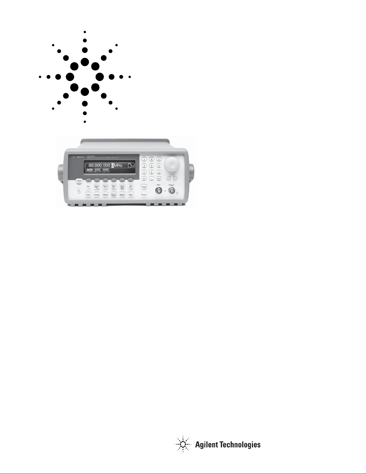
The Agilent Technologies 33250A Function/
Arbitrary Waveform Generator uses direct
digital-synthesis techniques to create a stable, accurate output on all waveforms, down
to 1µHz frequency resolution. The benefits
are apparent in every signal you produce,
from the sine wave frequency accuracy to the
fast rise/fall times of square waves, to the
ramp linearity.
Front-panel operation of the 33250A is
straightforward and user friendly. The knob
or numeric keypad can be used to adjust frequency, amplitude and offset. You can even
enter voltage values directly in Vpp, Vrms,
dBm, or high/low levels. Timing parameters
can be entered in hertz (Hz) or seconds.
Custom Waveform Generation
Why settle for a basic function generator
when you can get arbitrary waveforms at
no extra cost? With the 33250A, you can
generate arbitrary waveforms with 12-bit
vertical resolution, 64K memory depth,
and a sample rate of 200 MSa/s. You can
also store up to four 64K-deep arbitrary
waveforms in non-volatile memory with
user-defined names to help you find the right
waveform when you need it most.
Agilent 33250A
Function/Arbitrary
Waveform Generator
Data Sheet
The included Agilent IntuiLink software
allows you to easily create, edit, and download complex waveforms
Arbitrary Waveform Editor.
a waveform using IntuiLink oscilloscope or
DMM and send it to the 33250A for output.
For programmers, ActiveX components can
be used to control the instrument using
SCPI commands. IntuiLink provides the
tools to easily create, download, and manage waveforms for your 33250A. To find out
more about IntuiLink, visit www.agilent.
com/find/intuilink.
Pulse Generation
The 33250A can generate simple pulses
up to 50 MHz. With variable edge time,
pulse width and voltage level, the 33250A
is ideally suited to a wide variety of pulse
applications.
using the IntuiLink
Or you can capture
• 80 MHz sine and square wave outputs
• Sine, square, ramp, noise and other
waveforms
• 50 MHz pulse waveforms with variable
rise/fall times
• 12-bit, 200 MSa/s, 64K-point deep arbitrary waveform
Built-in Versatility
AM, FM and FSK capabilities make it easy
to modulate waveforms with or without
a separate source. Linear or logarithmic sweeps can be performed with a
programmable frequency marker signal.
Programmable burst count and gating allow
you to further customize your signal.
For system applications, both GPIB and
RS-232 interfaces are standard, and support
full programmability using SCPI commands.
Color Graphical Display
The unique design of the 33250A combines
a low-profile instrument withthe benefits
of a color graphical display. Now you can
display multiple waveform parameters at
the same time. The graphical interface also
allows you to modify arbitrary waveforms
quickly and easily.
Timebase Stability and Clock Reference
The 33250A TCXO timebase gives you
frequency accuracy of 2 ppm for your most
demanding applications. The external clock
reference input/output lets you synchronize
to an external 10MHz clock, to another
33250A, or to another Agilent 332XXA
Function/Arbitrary Wafeform Generator.
Phase adjustments can be made from the
front panel or via a computer interface,
allowing precise phase calibration
and adjustment.
Page 2

Waveforms
Standard sine, square, pulse,
ramp, noise, sin(x)/x,
exponential rise,
exponential fall,
cardiac, DC volts
Arbitrary
Waveform length 1 to 64K points
Amplitude resolution 12 bits (including sign)
Repetition rate 1 µHz to 25 MHz
Sample rate 200 MSa/s
Filter bandwidth 50 MHz
Non-vol. memory Four (4) 64K wave-
forms
Frequency Characteristics
Sine 1 µHz to 80 MHz
Square 1 µHz to 80 MHz
Pulse 500 µHz to 50 MHz
Arb 1 µHz to 25 MHz
Ramp 1 µHz to 1 MHz
White noise 50 MHz bandwidth
Resolution 1 µHz;
except pulse, 5digits
Accuracy (1 year) 2 ppm, 18°C to 28°C
3 ppm, 0°C to 55°C
Sinewave Spectral Purity
Harmonic distortion
≤ 3 Vpp
1
> 3 Vpp
DC to 1 MHz -60 dBc -55 dBc
1 MHz to 5 MHz -57 dBc -45 dBc
5 MHz to 80 MHz -37 dBc
2
-30 dBc
Total harmonic distortion
DC to 20 kHz < 0.2% + 0.1 mVrms
Spurious (non-harmonic)
3
DC to 1 MHz -60 dBc
1 MHz to 20 MHz -50 dBc
20 MHz 80 MHz -50 dBc + 6dBc/oc-
tave
Phase noise (30 kHz band)
10 MHz <-65 dBc (typical)
80 MHz <-47 dBc (typical)
Signal Characteristics
Squarewave
Rise/Fall time < 8 ns
Overshoot < 5%
Asymmetry 1% of period + 1 ns
Jitter (rms)
< 2 MHz 0.01% + 525 ps
≥ 2 MHz 0.1% + 75 ps
Duty cycle
≤ 25 MHz 20.0% to 80.0%
25 MHz to 50 MHz 40.0% to 60.0%
50 MHz to 80 MHz 50.0% (fixed)
Pulse
Period 20.00 ns to 2000.0 s
Pulse width 8.0 ns to 1999.9 s
Variable edge time 5.00 ns to 1.00 ms
Overshoot < 5%
Jitter (rms) 100 ppm + 50 ps
Ramp
Linearity < 0.1% of peak output
Symmetry 0.0% to 100.0%
Arb
Minimum edge time < 10 ns
Linearity < 0.1% of peak output
Settling time < 50 ns to 0.5% of final
value
Jitter (rms) 30 ppm + 2.5 ns
Output Characteristics
2
Amplitude (into 50Ω) 10 mVpp to 10 Vpp
Accuracy (at 1 kHz, >10 mVpp, Autorange on)
± 1% of setting ± 1
mVpp
Flatness (sinewave relative to 1 kHz,
Autorange on)
< 10 MHz ± 1% (0.1 dB)
10 MHz to 50 MHz ± 2% (0.2 dB)
50 MHz to 80 MHz ± 5% (0.4 dB)
Units Vpp, Vrms, dBm,
highand low level
Resolution 0.1 mV or 4 digits
Offset (into 50Ω) ± 5 Vpk ac + dc
Accuracy 1% of setting + 2 mV
+ 0.5% of amplitude
Waveform Output
Impedance 50Ω typical (fixed)
>10 MΩ (output dis-
abled)
Isolation 42 Vpk maximum to
earth
Protection short-circuit
protected
overload relay
automatically
disables main output
4
7
;
Modulation Characteristics
AM
Carrier waveforms sine, square, ramp, and
arb
Mod. waveforms sine, square, ramp,
noise, and arb
Mod. frequency 2 mHz to 20 kHz
Depth 0.0% to 120.0%
Source internal/external
FM
Carrier waveforms sine, square, ramp, and
arb
Mod. waveforms sine, square, ramp,
noise, and arb
Mod. frequency 2 mHz to 20 kHz
Peak deviation DC to 80 MHz
Source internal/external
FSK
Carrier waveforms sine, square, ramp, and
arb
Mod. waveform 50% duty cycle square
Internal rate 2 mHz to 100 kHz
Frequency range 1 µHz to 80 MHz
Source internal/external
External Modulation Input
Voltage range ± 5 V full scale
Input impedance 10 Ω
Frequency DC to 20 kHz
Latency < 70 µs typical
Burst
Waveforms sine, square, ramp,
5
pulse, arb, andnoise
Frequency 1 µHz to 80 MHz
8
Burst count 1 to 1,000,000 cycles
orinfinite
Start/Stop phase -360.0° to +360.0°
6
Internal period 1 ms to 500 s
Gate source external trigger
Trigger source single manual trigger,
internal, external trig
Trigger delay
N-cycle, infinite 0.0 ns to 85.000 sec
Sweep
Waveforms sine, square, ramp, and
arb
Type linear and logarithmic
Direction up or down
Start F/Stop F 100 µHz to 80 MHz
Sweep time 1 ms to 500 s
Trigger single manual trigger,
internal, external trig
Marker falling edge of sync
signal (programmable)
2
Page 3

System Characteristics
Configuration Times (typical)
9
Function change
Standard 100 ms
Pulse 660 ms
Built-in arb 220 ms
Frequency change 20 ms
Amplitude change 50 ms
Offset change 50 ms
Select user arb < 900 ms for < 16K pts.
Modulation change < 200 ms
Arb Download Times GPIB/RS-232 (115Kbps)
Arb Length Binary ASCII Integer ASCII Real
64K points 48 sec 112 sec 186 sec
16K points 12 sec 28 sec 44 sec
8K points 6 sec 14 sec 22 sec
4K points 3 sec 7 sec 11 sec
2K points 1.5 sec 3.5 sec 5.5 sec
Trigger Characteristics
Trigger input
Input level TTL compatible
Slope rising or falling,
(selectable)
Pulse width > 100 ns
Input impedance 10 kΩ, DC coupled
Latency
Burst < 100 ns (typical)
Sweep < 10 µs (typical)
Jitter (rms)
Burst 1 ns; except pulse,
300ps
Sweep 2.5 µs
Trigger output
Level TTL compatible into
50Ω
Pulse width > 450 ns
Maximum rate 1 MHz
Fanout ≤ 4 Agilent 33250A’s
(or equivalent)
Clock Reference
Phase Offset
Range -360° to +360°
Resolution 0.001°
External Reference Input
Lock range 10 MHz ± 35 kHz
Level 100 mVpp to 5 Vpp
Impedance 1 kΩ nominal, ac
coupled
Lock time < 2 s
Internal Reference Output
Frequency 10 MHz
Level 632 mVpp (0 dbm),
nominal
Impedance 50Ω nominal, ac
coupled
Sync Output
Level TTL compatible
into > 1kΩ
Impedance 50 Ω nominal
General
Power supply 100-240 V, 50-60 Hz
100-127 V, 50-400 Hz
Power consumption 140 VA
Operating temp. 0°C to 55°C
Storage temp. -30°C to 70°C
Stored states 4 named user configu rations
Power on state default or last
Interface IEEE-488 and
RS-232 std.
Language SCPI-1997, IEEE-488.2
Dimensions (WxHxD)
Bench top 254 x 104 x 374 mm
Rackmount 213 x 89 x 348 mm
Weight 4.6 kg
Safety designed to EN61010-1, CSA1010.1,
UL-311-1
EMC tested to IEC-61326-1
IEC-61000-4-3 criteria B
IEC-61000-4-6 criteria B
Vibration and shock MIL-T-28800E, Type III,
Class 5
Acoustic noise 40 dBA
Warm-up time 1 hour
Calibration interval 1 year
Warranty 1 year
1
Harmonic distortion at low amplitudes is limited by a -70 dBm floor
2
Harmonic distortion at 40 MHz only is -33 dBc
3
Spurious noise at low amplitudes is limited by a -75 dBm floor
4
Edge time decreased at higher frequency, 3.5 nS (typical)
5
20 mVpp to 20 Vpp into open-circuit load
6
dB rounded to 1 digit, instrument adheres to “%” specification
7
Short-circuit protected to ground at all times
8
Sine and square waveforms above 25 MHz only with infinite burst count
9
Time to change parameter and output new signal
3
Page 4

t
www.agilent.com
Ordering Information
Agilent 33250A
80 MHz Function/Arbitrary
Wavefrom Generator
Accessories included
Operating manual, service manual,
quick reference guide, IntuiLink waveform
editor software, test data, RS-232 cable,
and power cord (see language option).
Options
Opt. 0B0 Delete manual
Opt. 1CM Rackmount kit
(also sold as Agilent 34190A)
Opt. A6J ANSI Z540 calibration
Opt. AB0 Taiwan: Chinese manual
Opt. AB1 Korea: Korean manual
Opt. AB2 China: Chinese manual
Opt. ABA English: English manual
Opt. ABD Germany: German manual
Opt. ABF France: French manual
Opt. ABJ Japan: Japanese manual
Other Accessories
34131A Carrying case
34161A Accessory pouch
34190A Rackmount kit*
*
For racking two 33250As side-by-side, order the
following items: Lock-link kit (p/n 5061-9694),
Flange kit (p/n 5063-9212)
Agilent Email Updates
www.agilent.com/find/emailupdates
Get the latest information on the
products and applications you select.
Agilent Direc
www.agilent.com/find/agilentdirect
Quickly choose and use your test
equipment solutions with confidence.
Remove all doubt
Our repair and calibration services
will get your equipment back to you,
performing like new, when promised. You will get full value out of
your Agilent equipment throughout its lifetime. Your equipment
will be serviced by Agilent-trained
technicians using the latest factory
calibration procedures, automated
repair diagnostics and genuine parts.
You will always have the utmost
confidence in your measurements.
Agilent offers a wide range of additional expert test and measurement services for your equipment,
including initial start-up assistance
onsite education and training, as
well as design, system integration,
and project management.
For more information on repair and
calibration services, go to:
www.agilent.com/find/removealldoubt
For more information on Agilent
Technologies’ products, applications
or services, please contact your local Agilent office. The complete list is
available at:
www.agilent.com/find/contactus
Americas
Canada (877) 894-4414
Latin America 305 269 7500
United States (800) 829-4444
Asia Pacific
Australia 1 800 629 485
China 800 810 0189
Hong Kong 800 938 693
India 1 800 112 929
Japan 0120 (421) 345
Korea 080 769 0800
Malaysia 1 800 888 848
Singapore 1 800 375 8100
Taiwan 0800 047 866
Thailand 1 800 226 008
Europe & Middle East
Austria 01 36027 71571
Belgium 32 (0) 2 404 93 40
Denmark 45 70 13 15 15
Finland 358 (0) 10 855 2100
France 0825 010 700*
*0.125 €/minute
Germany 07031 464 6333
Ireland 1890 924 204
Israel 972-3-9288-504/544
Italy 39 02 92 60 8484
Netherlands 31 (0) 20 547 2111
Spain 34 (91) 631 3300
Sweden 0200-88 22 55
Switzerland 0800 80 53 53
United Kingdom 44 (0) 118 9276201
Other European Countries:
www.agilent.com/find/contactus
Revised: March 24, 2009
Product specifications and descriptions in this
document subject to change without notice.
© Agilent Technologies, Inc. 2009
Printed in USA May 5, 2009
5968-8807EN
 Loading...