

Page 1

Agilent Technologies 1670G Series
Benchtop Logic Analyzers
Technical Data
Affordable logic analyzers
designed for your exact needs
Agilent Technologies 1670G
Series benchtop logic analyzers
enable design engineers to
pur-chase a logic analyzer that
meets their exact needs and
their budget.
The 1670G Series models have the
option of a built-in, 500 MHz,
2 GSa/s oscilloscope that can be
triggered by the logic analyzer.
Some of the toughest hardware
debug problems can be found
only with the digital triggering
capabilities of a logic analyzer
and can be solved only with
the analog resolution of an
oscilloscope.
An optional pattern generator in
the 1670G Series allows designers
to substitute stimulus for missing
subsystems during product
development.
The 1670G Series helps simplify
the capture and analysis of
complex events with optional
256K or 2M deep memory. Deep
memory is a valuable logic
analyzer feature for debugging
embedded microprocessor
systems.
Figure 1. Agilent’s 1670G Series Benchtop Logic Analyzers Offer Deep Memory and Integrated
Oscilloscope or Pattern Generator Options.
Agilent Model Number 1670G 1671G 1672G 1673G
Channel count 136 102 68 34
Timing analysis speed 250/500 MHz (full/half channels)
State analysis speed 150 MHz
State clock/qualifiers 4 2
Memory depth/channel
[3]
64/128K (full/half channels)
with option 1
[1], [3]
256/512K
with option 2
[3]
2/4M
Option 3
[2]
2-channel, 500 MHz, 2 GSa/s, 32K
(oscilloscope) sample oscilloscope
Option 4 32-channel, 100/200 MHz, 256K
(pattern generator) vector pattern generator
Built-in display color
LAN port Thin LAN & Ethertwist
[1]
Choose memory option 1 or 2.
[2]
Choose either the scope or the pattern generator (compatible with option 1 or 2).
[3]
Time or state tags halve the acquisition memory when there are no unassigned pods.
The units include a VGA resolution color flat panel display to
help you find information
quickly. The user interface helps
to locate the source of designproblems in less time. You have
the option of using a mouse or
the front panel to easily navigate
through the user interface; a PC
style keyboard is also supported.
A compact all-in-one design helps
save space on a crowded lab
bench.
Page 2
2
Agilent Technologies 1670G Series Specifications
Features Benefits
State/timing analyzer Select the number of channels to match your application
(34, 68, 102, 136).
Optional deep memory 256K or 2M of memory allows capture and analysis of much
longer periods of execution. Helps solve poorly understood
or difficult to reproduce problems.
Optional oscilloscope An integrated oscilloscope can be triggered from the
analyzer (and vice versa) and provides the ability to view
analog and digital signals simultaneously.
Optional pattern An integrated pattern generator provides stimulus for
generator missing components, so that testing can begin before the
system is complete.
Trigger functions Trigger functions are depicted graphically and textually, and
may be combined to create custom trigger sequences for
capturing a complex series of events.
Global markers Track a symptom in one domain (e.g. timing) to its cause in
another domain (e.g. analog).
Documentation capability Save screen shots in standard TIFF, PCX, and EPS formats on
disk. Print screen shots and trace listings to a local
printer. Save acquired data in ASCII format for post
processing.
Processor and bus Quickly and reliably connect to a wide variety of specific
support processors and buses. Inverse assemblers allow data to be
viewed at the assembly level.
LAN Ethertwist and ThinLAN connectors support FTP, PC/NFS
protocols, and work with X11 windows packages. Users can
program the analyzer, archive data, and setup files via telnet
sockets.
Probing A wide variety of IC clips, QFP adapters, QFP probes, and
headers are available to help connect the analyzer to the
system under test.
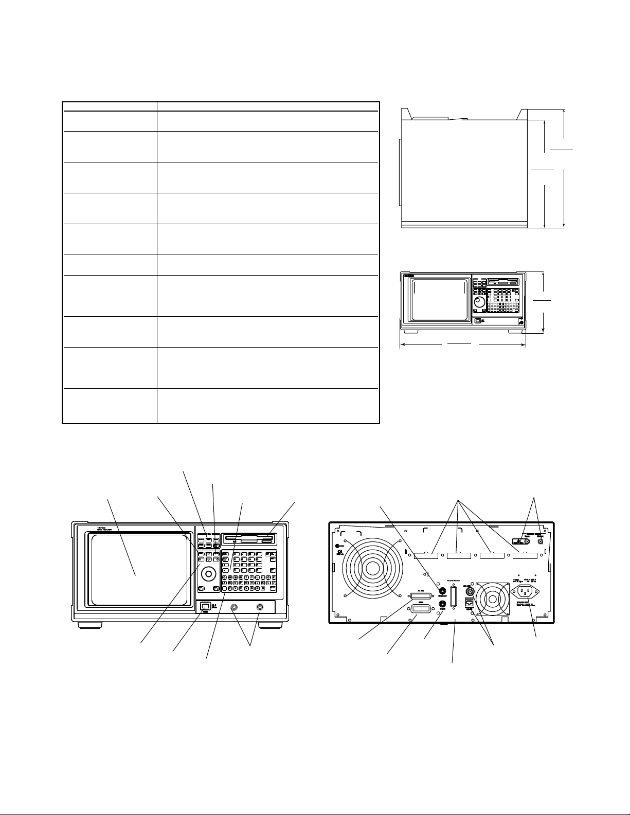
13.0 in.
330 mm
14.5 in.
367 mm
8.1 in.
205 mm
17.3 in.
440 mm
Weight = 28.6 lbs.
13 kg
Figure 2. Logic Analyzer Dimensions and Weight
Quick memu keys
Done key
Display
Select key
data entry keys Disk drive
Movement keys
Power on/off
Oscilloscope channel
Shift key
Pods
External
trigger BNCs
Keyboard
Mouse
RS-232C Connector
Line power
module
Parallel printer
connector
GPIB Connector
LAN
Connectors
Figure 3. Diagram of Logic Analyzer’s Front and Rear Panels
Page 3
3
Agilent Technologies 1670G Series Annotated Screen Shots
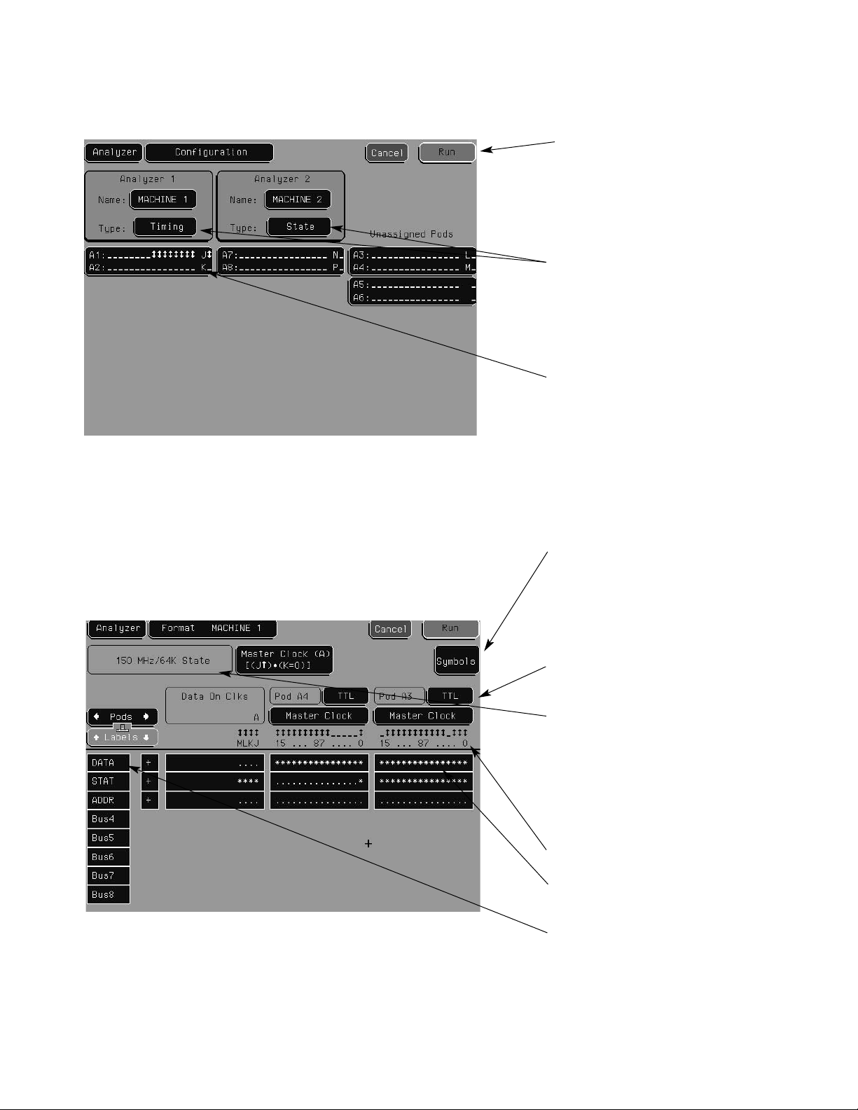
Figure 4. Configuration Screen
Figure 5. Format Screen
Run—starts data acquisition in
specified trace mode.
Stop—halts acquisition and displays current data.
Acquisition mode and number of
channels (assign pods) are specified. Timing and State measurements can be taken
simultaneously.
Activity indicators allow users to
monitor device-under-test activity
during analyzer setup.
User mnemonics defined (for bit
patterns or ranges), or up to 1000
symbols extracted from popular
object module formats. In symbol
mode, symbols will be dis-played
in place of data.
Logic threshold levels.
State speed can be specified
when analyzer is in state mode.
Full channel (250 MHz) or half
channel (500 MHz) can be specified in timing mode. (Screen shot
is in state mode.)
Activity indicators.
Appropriate channels assigned to
a label.
Channels can be grouped and
given a 6-character label.
Maximum of 126 labels with up to
32 channels each.
Page 4
4
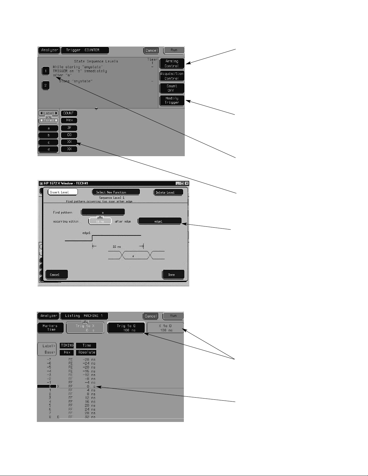
Figure 6. Trigger Screen
Figure 7. Graphical Trigger Function
Figure 8. Listing Display
Analyzer and oscilloscope or
pattern generator can cross-arm
each other. Arming is started by
Run, Group Run, or the PortIn
BNC (rising edge). PortOut is
asserted as a rising edge at the
PortOut BNC.
Twenty-three trigger functions
(shown graphically and textually)
can be combined to create custom
trigger sequences.
Up to twelve sequence levels with
branching and timers can be
defined.
Ten pattern recognizers (and bit
patterns in each label) can be
defined.
Edge terms make it easy to trigger
on rising or falling edges on any
number of specified signals. They
can also be used to trigger on
glitches to 3.5 ns.
Knob (or hold down right mouse
button) scrolls through listing display.
Markers measure the time
between events, search for specific events, and gather statistical
data.
Trigger is located at line 0.
Page 5
5
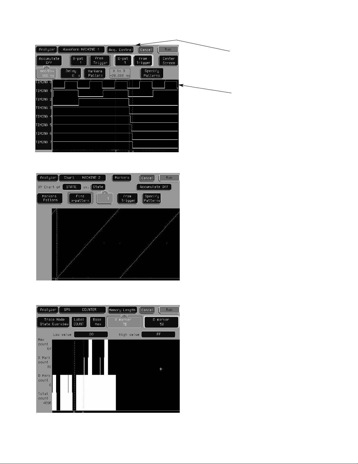
Figure 9. Waveform Display
Figure 10. Chart Display (State Mode Only)
Figure 11. System Performance Analyzer (SPA)
Accumulate—waveform is not
erased between successive
acquisitions (persistence).
All displays are time-correlated,
so the trigger, x, and o markers
are located at equivalent positions in time on each display.
Overlay—multiple channels displayed on one line, with value in
selected base if space permits.
Maximum of 24 lines per screen;
may scroll through up to 96 lines.
Chart mode plots the value of a
specified label (on y-axis) versus
a state number or another label
(on x-axis). Both axes can be
scaled. Useful for A/D converters
and obtaining a visual overview
of bus activity (address flow or
data flow).
There are three SPA modes available: State Overview (shown here
provides a visual indication of
memory use), State Histogram (%
time spent in each function), and
Time Interval (execution time of a
particular function).
Page 6
6
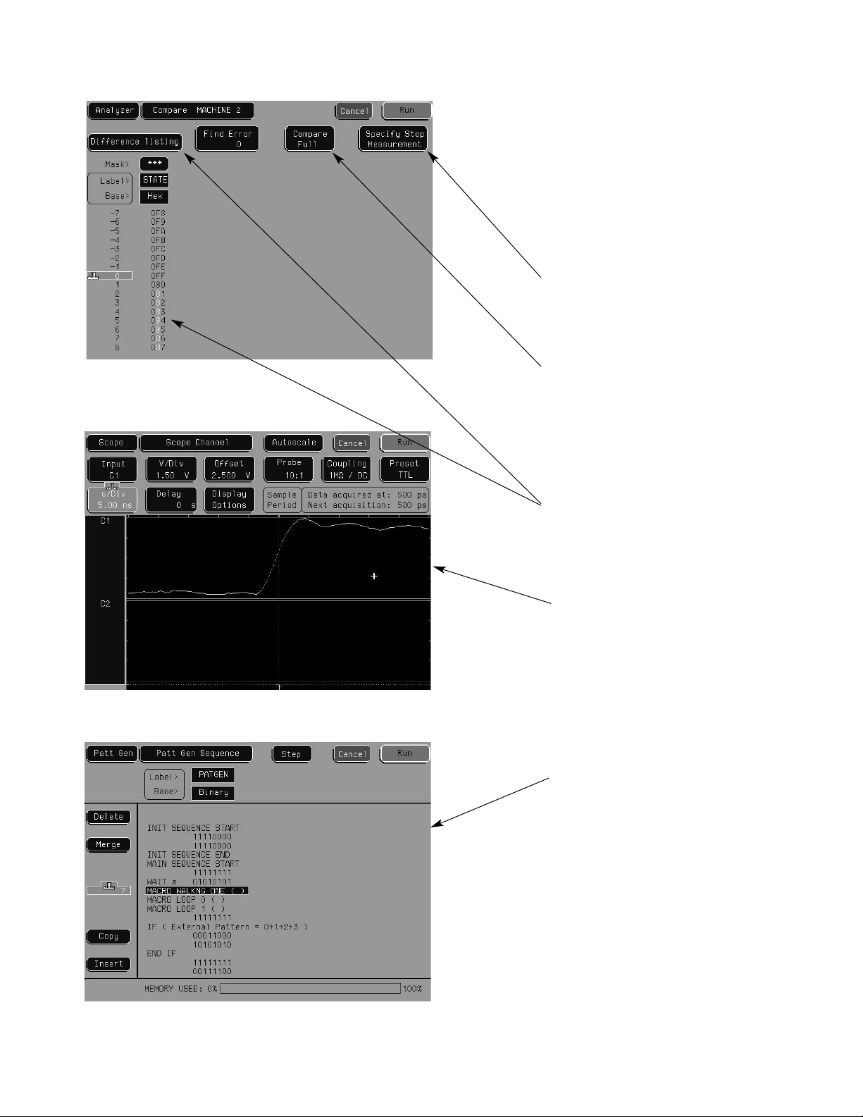
Figure 12. Compare Screen
(State Mode Only)
Figure 13. Oscilloscope Display (Option 003)
Figure 14. Pattern Generator Sequence Window (Option 004)
Compare performs a
post-processing, bit-by-bit
comparison of acquired state
data and compare image data.
Copy state acquisition into
compare image buffer (may edit
any bit in compare image). The
compare feature halves the
memory depth (1/4 memory
with Opt. 002)
Stop Measurement halts
repetitive acquisitions when
current and compare acquisitions
are equal or not equal.
Compare Partial allows masking
of a compare image in order to
compare only certain bits or
set ranges of states (rows). (It
compares data that falls within
enabled channels and specified
range.)
Difference Listing highlights
differences between the current
state listing and compare image.
(Reference listing shows
com-pare image and bit masks.)
Several different views of the
oscilloscope display are available,
each offering different control
options. The Scope Channel
display is shown here.
The pattern generator allows the
user to create data streams from
provided macros or from various
external sources and use them to
stimulate a target. Since the pattern generator is internal to the
logic analyzer, the target response
can be measured with the logic
analyzer to identify incorrect
output and potential target
system malfunction.
Page 7
7
Agilent Technologies 1670G Series
Specifications and Characteristics
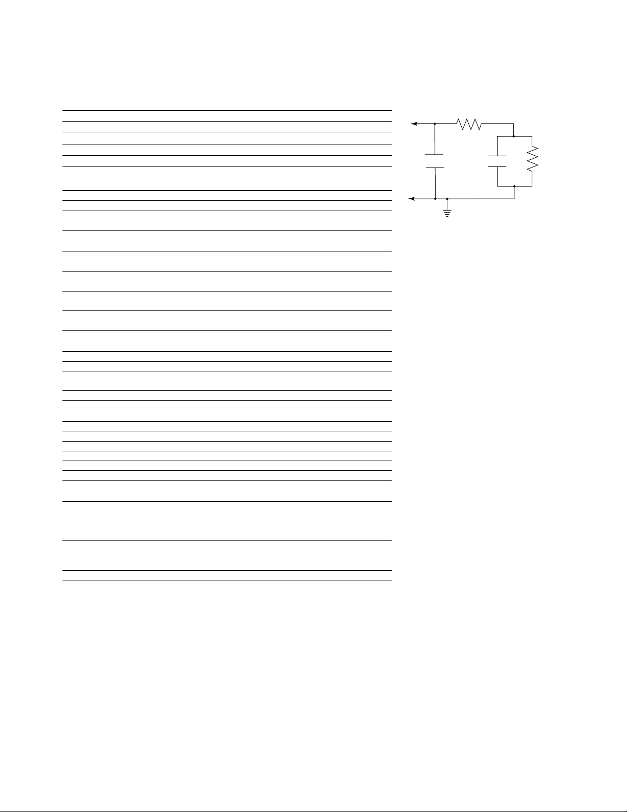
Probes (general-purpose lead set)
Input resistance 100 kΩ, ±2%
Parasitic tip capacitance 1.5 pF
Minimum voltage swing 500 mV, peak-to-peak
Threshold accuracy* ±(100 mV + 3% of threshold setting)
Maximum input voltage ±40 V peak
State Analysis
Minimum state clock pulse width 3.5 ns
Time tag resolution
[3]
8 ns or ± 0.1% (whichever is greater)
Maximum time count
between states 34.4 seconds
Maximum state tag
count between states
[3]
4.29 x 10⁹states
Minimum master-to-master
clock time* 6.67 ns
Minimum master-to-slave
clock time 0.0 ns
Minimum slave-to-master
clock time 4.0 ns
Clock qualifier
setup/hold 4.0/0 ns fixed
Timing Analysis
Sample period accuracy 0.01% of sample period
Channel-to-channel skew 2 ns typical (not > 3 ns)
Time interval accuracy ± (sample period accuracy + channel-to-channel
skew + 0.01% of time interval reading)
Minimum detectable glitch 3.5 ns
Triggering
Sequencer speed >150 MHz
Maximum occurrence counter 1,048,575
Range width 32 bits each
Timer value range 400 ns to 500 seconds
Timer resolution 16 ns or 0.1% (whichever is greater)
Timer accuracy ±32 ns or ±0.1% (whichever is greater)
Operating Environment
Temperature Instrument: 0°C to 55° C (+32°F to 131°F)
Disk media: 10°C to 40°C (+50°F to 104°F)
Probe lead sets and cables:
0°C to 65°C (+32°F to 149°F)
Humidity Instrument: up to 95% relative humidity at +40° C
Disk media and hard drive: 8% to 85% relative
humidity
Altitude 4,572 m (15,000 ft)
[3]
Time or state tags halve the acquisition memory when there are no unassigned pods.
* Warranted Specifications
Figure 15. Equivalent Probe Load for the
01650-61608 General-Purpose Lead Set.
370 ohms
1.5pF 7.4pF
GROUND
100 K
ohm
Page 8

8
PortIn arms logic analyzer 15 ns typical delay from signal input to a don’t care
logic analyzer trigger
PortIn arms oscilloscope 40 ns typical delay from signal input to an immediate
oscilloscope trigger.
Logic analyzer arms PortOut 120 ns typical delay from logic analyzer trigger to
signal output.
Oscilloscope arms PortOut 60 ns typical delay from oscilloscope trigger
to signal output
Arming skew Correction factors for nominal skew between displayed
timing and oscilloscope signals are built into the operating
system. Additional correction for unit-by-unit variation can
be made using the Skewfield. An entered skew value
effects the next (not the present) acquisition display.
Timing Analysis
Conventional timing Minimum sample period 4 ns / 2 ns, maximum sample
period 10 µs /2.5 µs.
Time covered = sample period x memory depth.
Printing Screen images can be printed in black and white or color
from all menus using the Print field. State or timing listings
can also be printed in full or part (starting from center
screen) using the Print All selection. Printers that use
the HP Printer Control Language (PCL) and have a parallel
Centronics, RS-232, or GPIB interface are supported.
Supported printers: HP DeskJet, LaserJet, QuietJet,
PaintJet, and ThinkJet models, as well as Epson FX80,
LX80, and MX80 printers with RS-232 or Centronics
interfaces in Epson 8-bit graphics mode.
Mass storage 2 GB internal hard disk drive, 1.44 Mbyte, 3.5-inch flexible
disk drive. The logic analyzer’s operating system resides
in Flash ROM and can be updated from the flexible disk
drive or from the internal hard disk drive.
File formats TIFF, color PCX, or black and white Encapsulated
Adobe ® PostScript ® (EPS) formats
Config files Logic analyzer and oscilloscope files that include
configuration and data information (if present) are
encoded in a binary format. They can be stored to or
loaded from the hard disk drive or a flexible disk. Binary
format configuration/data files are stored with the time of
acquisition and the time of storage
Trigger Resources
Patterns 10
Ranges 2
Edge and glitch 2 terms (timing only)
Timers 2
Occurrence counters 4
Trigger sequence levels 12 state / 10 timing
Setup/hold time 3.5/0 ns to 0/3.5 ns in .5 ns increments
Threshold range TTL, ECL, user-definable ±6.0 V adjustable
in 50 mV increments
Adobe ®PostScript ®is a registered trademark of Adobe Systems Incorporated.
Page 9

9
Agilent Technologies 1670G Series (Option 003)
Oscilloscope Specifications and Characteristics
General Information
Model number 1670G Option 003
Number of channels 2
Maximum sample rate 2 GSa/s per channel
Bandwidth
[4] [8]
dc to 500 MHz (real time, dc coupled)
Rise time
[5] [8]
700 ps
Vertical resolution 8 bits full scale
Memory depth 32K samples
Oscilloscope Probing
Input coupling 1 MΩ: ac,dc
50 Ω: dc only
Input resistance
[8]
1MΩ ±1%
50Ω ±1%
Input capacitance ~ 7pF
Probes included Two Agilent 1160A probes; (10:1, 10 MΩ 9 pF 1.5 meters)
Vertical (at BNC)
Maximum safe input voltage 1 MΩ : ±250 V
50 Ω : 5 V rms
Vertical sensitivity range (1:1 Probe) 16 mV full scale to 40 V full scale
Probe factors Any integer ratio from 1:1 to 1000:1
Vertical (dc) gain accuracy
[6]
± 1.25% of full scale
dc offset range (1:1 probe) ± 2V to ± 250V (depending on the vertical sensitivity)
dc offset accuracy
[8]
± [1.0% of channel offset + 2.0% of full scale]
Voltage measurement accuracy
[8]
± [1.25% of full scale + offset accuracy + 0.016 V/div]
Channel-to-channel isolation dc to 50 MHz – 40 dB; 50 MHz to 500 MHz – 30 dB
[4]
Upper bandwidth reduces by 2.5 MHz for every degree C above 35°C.
[5]
Rise time calculated as tr= 0.35
bandwidth
[6]
Vertical gain accuracy decreases 0.08% per degree C from software calibration temperature.
[7]
Specification applies at the maximum sam-pling rate. At lower rates, replace 150 ps in the formula with ( 0.15 x sample
interval) where sample interval is defined as 1/sample rate.
[8]
Specifications valid within ± 10°C of auto-calibration temperature.
Page 10

10
Horizontal
Time base range 0.5 ns/div to 5 s/div
Time interval measurement accuracy
[7] [8]
± [(0.005% of ∆t) + (2x10⁻⁶x delay setting) + 150 ps]
Oscilloscope Triggering
Trigger level range Bounded within channel display window
Trigger sensitivity
[8]
dc to 50 MHz: 0.063 x Full Scale
50 MHz to 500 MHz: 0.125 x Full Scale
Trigger modes
Immediate Triggers immediately after arming condition is met.
(Arming condition is Run, Group Run, Cross Arming
Signal, or Port In BNC signal).
Edge Triggers on rising or falling edge from channel 1 or 2.
Pattern Triggers on entering or exiting logical pattern specified
across channels 1 or 2. Each channel can be specified
as high (H), low (L), or don't care (X) with respect to the
level settings in the edge trigger menu. Patterns must
be >1.75 ns in duration to be recognized.
Time-qualified pattern Triggers on the exiting edge of a pattern that meets
the user-specified duration criterion. Greater than, less
than, or within range duration criterion can be used.
Duration range is 20 ns to 160 ns. Recovery time after
valid patterns with invalid duration is <12 ns.
Events delay Triggers on the nth edge or pattern as specified by the
user. Time-qualification is applied only to the 1st of n
patterns.
Auto-trigger Self-triggers if no trigger condition is found ~ 50 ms
after arming.
Measurement Functions
Time markers Two markers (x and o) measure time intervals
manually, or automatically with statistics.
Voltage markers Two markers (a and b) measure voltage and voltage
differences.
Automatic measurements Period, frequency, rise time, fall time, +width, –width,
peak-to-peak voltage, overshoot, and undershoot.
[4]
Upper bandwidth reduces by 2.5 MHz for every degree C above 35°C.
[5]
Rise time calculated as tr= 0.35
bandwidth
[6]
Vertical gain accuracy decreases 0.08% per degree C from software calibration temperature.
[7]
Specification applies at the maximum sam-pling rate. At lower rates, replace 150 ps in the formula with ( 0.15 x sample
interval) where sample interval is defined as 1/sample rate.
[8]
Specifications valid within ± 10°C of auto-calibration temperature.
Page 11

11
Agilent Technologies 1670G Series (Option 004)
Pattern Generator Specifications and Characteristics
Maximum memory depth 258,048 vectors
Number of output channels at 100 MHz to 200 MHz clock 16
Number of output channels at ≤100 MHz clock 32
Maximum number of labels 126
Maximum width of a label 32 bits
Maximum number of "IF Condition" blocks at ≤50 MHz clock 1
Maximum number of different macros 100
Maximum number of lines in a macro 1024
Maximum number of parameters in a macro 10
Maximum number of macro invocations 1,000
Maximum loop count in a repeat loop 20,000
Maximum number of repeat loop invocations 1,000
Maximum number of wait event patterns 4
Number of input lines to define a wait pattern 3
Lead Set Characteristics
10474A 8-channel probe lead set Provides most cost effective lead set for the
1670G Series clock and data pods. IC clips are
not included.
10347A 8-channel probe lead set Provides 50 Ω coaxial lead set for unterminated
signals, required for Agilent 10465A ECL Data Pod
(unterminated). IC clips are not included.
Data Pod Characteristics
10461A TTL Data Pod
Output type 10H125 with 100 Ω series
Maximum clock 200 MHz
Skew (note 1) typical < 2 ns; worst case = 4 ns
Recommended lead set Agilent 10474A
10462A 3-STATE TTL/CMOS Data Pod
Output type (note 2) 74ACT11244 with 100 Ω series; 10H125 on non 3-state channel 7
3-State enable negative true, 100 KΩ to GND, enabled on no connect
Maximum clock 100 MHz
Skew (note 1) typical < 4 ns; worst case = 12 ns
Recommended lead set Agilent 10474A
Note 1: Typical skew measurements made at pod connector with approximately 10 pF/50 kΩ load to GND; worst case skew
numbers are a calculation of worst case conditions through circuits.
Note 2: Channel 7 on the 3-state pods has been brought out in parallel as a non 3-state signal. By looping this output back into the
3-state enable line, the channel can be used as a 3-state enable.
ECL/TTL
10H125
100Ω
74ACT11244
100Ω
Page 12

12
10464A ECL Data Pod (Terminated)
Output type 10H115 with 330 Ω pulldown, 47 Ω series
Maximum clock 200 MHz
Skew (note 1) Typical < 1 ns; worst case = 2 ns
Recommended lead set Agilent 10474A
10465A ECL Data Pod (Unterminated)
Output type 10H115 (no termination)
Maximum clock 200 MHz
Skew (note 1) Typical < 1 ns; worst case = 2 ns
Recommended lead set Agilent 10347A
10H115
47Ω
330Ω
-5.2V
10H115
10469A 5 Volt PECL Data Pod
Output type 100EL90 (5V) with 348 Ω pulldown to ground and 42 Ω in series
Maximum clock 300 MHz
Skew (note 1) Typical < 500 ps; worst case = 1 ns
Recommended lead set Agilent 10498A
100EL90
42Ω
348Ω
10471A 3.3 Volt LVPECL Data Pod
Output type 100LVEL90 with 215 Ω pulldown to ground and 42 Ω in series
Maximum clock 300 MHz
Skew (note 1) Typical < 500 ps; worst case = 1 ns
Recommended lead set Agilent 10498A
100LVEL90
42Ω
215Ω
Note 1: Typical skew measurements made at pod connector with approximately 10 pF/50 kΩ load to GND; worst case skew
numbers are a calculation of worst case conditions through circuits.
Note 2: Channel 7 on the 3-state pods has been brought out in parallel as a non 3-state signal. By looping this output back into
the 3-state enable line, the channel can be used as a 3-state enable.
Page 13
13
10473A 3-STATE 2.5 Volt Data Pod
Output type 74AVC16244
3-state enable negative true, 38KΩ to GND, enable on no connect
Maximum clock 300 MHz
Skew (note 1) typical < 1.5 ns; worst case = 2 ns
Recommended lead set Agilent 10498A
74AVC16244
10476A 3-STATE 1.8 Volt Data Pod
Output type 74AVC16244
3-state enable negative true, 38KΩ to GND, enable on no connect
Maximum clock 300 MHz
Skew (note 1) typical < 1.5 ns; worst case = 2 ns
Recommended lead set Agilent 10498A
74AVC16244
10483A 3-STATE 3.3 Volt Data Pod
Output type 74AVC16244
3-state enable negative true, 38KΩ to GND, enable on no connect
Maximum clock 300 MHz
Skew (note 1) typical < 1.5 ns; worst case = 2 ns
Recommended lead set Agilent 10498A
74AVC16244
Note 1: Typical skew measurements made at pod connector with approximately 10 pF/50 kΩ load to GND; worst case skew
numbers are a calculation of worst case conditions through circuits.
Note 2: Channel 7 on the 3-state pods has been brought out in parallel as a non 3-state signal. By looping this output back into
the 3-state enable line, the channel can be used as a 3-state enable.
10E156
or
10E154
-5.2V
Differential
Output
1KΩ
Data Cable Characteristics Without a Data Pod
The Agilent pattern generator data cables without a data pod provide an ECL terminated (1 KΩ to
–5.2V) differential signal (from a type 10E156 or 10E154 driver). These are usable when received
by a differential receiver, preferably with a 100 Ω termination across the lines. These signals
should not be used single ended due to the slow fall time and shifted voltage threshold (they are
not ECL compatible).
Agilent 1670C-Series (Option 004) Data Cable Output
1KΩ
-5.2V
Page 14

14
CLKin
Clock Pod Characteristics
10460A TTL Clock Pod
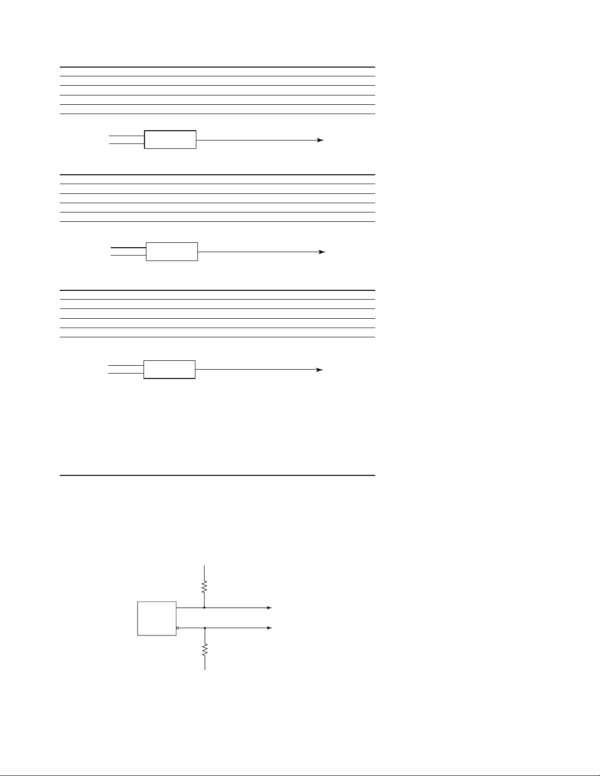
Clock output type 10H125 with 47 Ω series; true & inverted
Clock output rate 100 MHz maximum
Clock out delay 11 ns maximum in 9 steps
Clock input type TTL – 10H124
Clock input rate dc to 100 MHz
Pattern input type TTL – 10H124 (no connect is logic 1)
Clock-in to clock-out approximately 30 ns
Pattern-in to recognition approx. 15 ns + 1 clk period
Recommended lead set Agilent 10474A
10463A ECL Clock Pod
Clock output type 10H116 differential unterminated; and differential with
330 Ω to –5.2V and 47 Ω series
Clock output rate 200 MHz maximum
Clock out delay 11 ns maximum in 9 steps
Clock input type ECL – 10H116 with 50 KΩ to –5.2V
Clock input rate dc to 200 MHz
Pattern input type ECL – 10H116 with 50 KΩ (no connect is logic 0)
Clock-in to clock-out approximately 30 ns
Pattern-in to recognition approx. 15 ns + 1 clk period
Recommended lead set Agilent 10474A
10468A 5 Volt PECL Clock Pod
Clock output type 10EL90 (5V) with 348 Ω pulldown to ground and 42 Ω in series
Clock output rate 300 MHz maximum
Clock out delay 11 ns maximum in 9 steps
Clock input type 100EL91 PECL (5V), no termination
Clock input rate dc to 300 MHz
Pattern input type 100EL91 PECL (5V), no termination (no connect is logic 0)
Clock-in to clock-out approximately 30 ns
Pattern-in to recognition approx. 15 ns + 1 clk period
Recommended lead set Agilent 10498A
42Ω
348Ω
100EL90
100EL91
CLKout
CLKin
10H125
47Ω
WAIT
10H124
CLKout
10H116
50 kΩ
VBB
CLKin
10H116
47Ω
330Ω
-5.2V
-5.2V
CLKout
Page 15

15
10470A 3.3 Volt LVPECL Clock Pod
Clock output type 10LVEL90 (3.3V) with 215 Ω pulldown to ground and 42 Ω
in series
Clock output rate 300 MHz maximum
Clock out delay 11 ns maximum in 9 steps
Clock input type 100LVEL91 LVPECL (3.3V), no termination
Clock input rate dc to 300 MHz
Pattern input type 100LVEL91 LVPECL (3.3V), no termination (no connect is logic 0)
Clock-in to clock-out approximately 30 ns
Pattern-in to recognition approx. 15 ns + 1 clk period
Recommended lead set Agilent 10498A
42Ω
215Ω
100LVEL90
100LVEL91
CLKout
CLKin
10472A 2.5 Volt Clock Pod
Clock output type 74AVC16244
Clock output rate 200 MHz maximum
Clock out delay 11 ns maximum in 9 steps
Clock input type 74AVC16244 (3.6V max.)
Clock input rate dc to 200 MHz
Pattern input type 74AVC16244 (3.6V max; no connect is logic 0)
Clock-in to clock-out approximately 30 ns
Pattern-in to recognition approx. 15 ns + 1 clk period
Recommended lead set Agilent 10498A
WAIT
74AVC16244
74AVC16244
CLKout
CLKin
10475A 1.8 Volt Clock Pod
Clock output type 74AVC16244
Clock output rate 200 MHz maximum
Clock out delay 11 ns maximum in 9 steps
Clock input type 74AVC16244 (3.6V max.)
Clock input rate dc to 200 MHz
Pattern input type 74AVC16244 (3.6V max; no connect is logic 0)
Clock-in to clock-out approximately 30 ns
Pattern-in to recognition approx. 15 ns + 1 clk period
Recommended lead set Agilent 10498A
WAIT
74AVC16244
74AVC16244
CLKout
CLKin
Page 16

16
10477A 3.3 Volt Clock Pod
Clock output type 74AVC16244
Clock output rate 200 MHz maximum
Clock out delay 11 ns maximum in 9 steps
Clock input type 74AVC16244 (3.6V max.)
Clock input rate dc to 200 MHz
Pattern input type 74AVC16244 (3.6V max; no connect is logic 0)
Clock-in to clock-out approximately 30 ns
Pattern-in to recognition approx. 15 ns + 1 clk period
Recommended lead set Agilent 10498A
WAIT
74AVC16244
74AVC16244
CLKout
CLKin
Page 17

17
Probing the device under test is
both one of the potentially most
difficult and certainly one of
the most important tasks in
debugging a digital design. That
is why Agilent Technologies
provides a wider variety of
probing solutions than anyone
else in the industry—each with a
different set of advantages
particular to a given situation. We
like to think of it as helping you
get your signals off to a great
start.
Probing Alternatives
Probing Alternative Advantages Limitations
General-Purpose Most flexible method. Works in Can be cumbersome
Lead Sets and Surface conjunction with SMD clips and Wedge when connecting
Mount IC Clips adapters listed below. Included with a large number
(Figure 16 and 17) logic analyzer purchase. of channels.
Ultra-Fine Pitch Surface Smallest IC clips in the industry to date Same as above plus
Mount Device Clips (down to 0.5 mm). Works with both logic small incremental cost.
(Figure 18) analyzer and scope probing systems. _
Wedge probe adapter Compressible dual conductors between Same as above plus
for QFP Packages adjacent IC legs make 3-16 adjacent signal small incremental cost.
(Figure 19) leads available to logic analyzer and
scope probing systems.
Elastomeric and Locator Provides access to all signal leads for Requires minimal
Base Solutions for Generic generic QFP packages (including custom keep out area.
QFP Packages ICs). Uses combination of one probe Moderate to significant
(Figure 20) adapter and four flexible adapters, plus incremental cost.
general-purpose lead sets.
Direct Connection to Very reliable and convenient probing Requires advance
Device Under Test via system when frequent probing planning to integrate
Built-In Connectors connections are required (manufacturing into design process.
(Figure 21 and 22) or field test for example). Connectors Moderate (normal
can be located at optimal position in density) to significant
the device under test. Can work in (high density)
conjunction with Agilent provided incremental cost.
inverse assemblers.
Analysis Probes Support for over 200 different Requires moderate
for Specific Processors processors and buses. Includes clearance around
and Buses reliable logic analyzer probe processor or bus.
pod connectors, logic analyzer Moderate to significant
configuration files and device extra cost depending on
specific inverse assemblers. specific processor or bus.
Figure 16. General-Purpose Lead Sets
Figure 17. Surface Mount IC Clips Figure 18. Ultra-Fine Pitch Surface Mount
Device Clips
Figure 19. Agilent Wedge Probe Adapters for
QFP Package
Agilent Wedge Probe Adapter
IC leg spacing Number of signals Number of wedges in pack Model number
0.5 mm 3 1 E2613A
0.5 mm 3 2 E2613B
0.5 mm 8 1 E2614A
0.5 mm 16 1 E2643A
0.65 mm 3 1 E2615A
0.65 mm 3 2 E2615B
0.65 mm 8 1 E2616A
0.65 mm 16 1 E2644A
Page 18

18
Agilent Probing Solutions
Package type Pin Pitch Elastomeric Solutions
304-pin PQFP/CQFP 0.5 mm
240-pin PQFP/CQFP 0.5 mm E5363A probe adapter
E5371A 1/4-flexible adapter
208-pin PQFP/CQFP 0.5 mm E5374A probe adapter
E5371A 1/4-flexible adapter
184-pin PQFP/CQFP 0.5 mm
176-pin PQFP 0.5 mm E5348A probe adapter
E5349A 1/4-flexible adapter
160-pin QFP 0.5 mm E5377A probe adapter
E5349A 1/4-flexible adapter
160-pin PQFP/CQFP 0.65 mm E5373A probe adapter
E5349A 1/4-flexible adapter
144-pin PQFP/CQFP 0.65 mm E5361A probe adapter
E5340A 1/4-flexible adapter
144-pin TQFP 0.5 mm E5336A probe adapter
E5340A 1/4 flexible adapter
Figure 20. Elastomeric Probing Solution
Analysis Probes for Specific Processors and Buses
Please see Processor and Bus Support for Agilent Logic Analyzers
(pub. no. 5966-4365E) for detailed information and ordering
instructions for analysis probes. Also, see Probing Solutions for
Agilent Logic Analysis Systems (pub. no. 5968-4632E) for more
information on probing.
Figure 21. High-Density Direct Connection Solution
Figure 22. Normal-Density Direct
Connection Solution
Agilent E5346A
high-density
adapter cable
Probe cables
from logic
analyzer
Mictor (Agilent
part number
E5346-68701)
Optional shroud
(Agilent part number
E5346-44701)
Internal RC
network
Probe cables
from logic
analyzer
Termination
adapter (Agilent
part number
01650-63203)
20-pin connector
(Agilent part number
1251-8106 2 x 10 pin
header with 0.1” x
0.1” spacing)
Page 19

19
Accessories for the Agilent 1670G Series
Logic Analyzers
Figure 23. Agilent 1182B Standard Testmobile
Figure 25. Agilent 1160 Probes and Accessories
Figure 24. Agilent 1184A Deluxe Testmobile
Oscilloscope Probes
Agilent 1160 Family of
Miniature Passive Probes
The Agilent 1160 miniature
probes were developed as a result
of intensive market research. We
developed a probe with a browser
that won’t slip off the test point
being probed and short to some
adjacent point. The browser uses
a crown point that digs into solder and won’t slip. These probes
include a variety of ground leads
and 50 mil SMD clips for
attaching to different grounding
points. Each 1670G Series logic
analyzer with Option 003 ships
with the 1160 family passive
probes.
Each 1160 family probe
includes:
•1 probe assembly
•1 general-purpose retractable
hook tip
•1 browser
•2 barrel insulators
•4 spring grounds
•1 alligator ground lead
•1 socketed ground lead
•1 dual lead adapter
•2 SMD IC clips
•1 spare browser pogo pin
•1 spare probe tip
•1 screwdriver
•1 users’ reference
•3-year warranty
The Agilent 1170A low-mass passive probe is also available. (See ordering information for Optional Oscilloscope Probes.)
Page 20

20
Agilent 1670G Series
Ordering Information
Agilent 1670G Series Benchtop Logic Analyzers
Analyzer Description
1670G 136-Channel Color Logic Analyzer
1671G 102-Channel Color Logic Analyzer
1672G 68-Channel Color Logic Analyzer
1673G 3 4-Channel Color Logic Analyzer
Option 003 Oscilloscope Option
Option 004 Pattern Generator Option +
Option 005 Training Kit
Note: Customers may choose either a scope or a pattern generator (not both) and one memory option.
Agilent 1670G Series Product Options
Opt OB1 Additional User Manual . . . . . . . . . . . . . . . . . . . . . . . . . . . . . . . . . . . . . . . . . . . . . . . . . . . . . . . . . . . . . . . . . . . . . . . . . . . . . . . . .
Opt OB3 Add Service Manual . . . . . . . . . . . . . . . . . . . . . . . . . . . . . . . . . . . . . . . . . . . . . . . . . . . . . . . . . . . . . . . . . . . . . . . . . . . . . . . . . . . .
Opt OBF Add Programming Manual . . . . . . . . . . . . . . . . . . . . . . . . . . . . . . . . . . . . . . . . . . . . . . . . . . . . . . . . . . . . . . . . . . . . . . . . . . . . . . .
Opt ICM Rack Mount Kit . . . . . . . . . . . . . . . . . . . . . . . . . . . . . . . . . . . . . . . . . . . . . . . . . . . . . . . . . . . . . . . . . . . . . . . . . . . . . . . . . . . . . . . .
Opt IBP Standards Compliant Calibration . . . . . . . . . . . . . . . . . . . . . . . . . . . . . . . . . . . . . . . . . . . . . . . . . . . . . . . . . . . . . . . . . . . . . . . . . .
Opt ABJ Japanese Localization of User Manual . . . . . . . . . . . . . . . . . . . . . . . . . . . . . . . . . . . . . . . . . . . . . . . . . . . . . . . . . . . . . . . . . . . .
Opt UK9 Front Panel Cover . . . . . . . . . . . . . . . . . . . . . . . . . . . . . . . . . . . . . . . . . . . . . . . . . . . . . . . . . . . . . . . . . . . . . . . . . . . . . . . . . . . . . .
Opt W30 3-Year Extended Repair Service . . . . . . . . . . . . . . . . . . . . . . . . . . . . . . . . . . . . . . . . . . . . . . . . . . . . . . . . . . . . . . . . . . . . . . . . . .
Opt W50 5-Year Extended Repair Service . . . . . . . . . . . . . . . . . . . . . . . . . . . . . . . . . . . . . . . . . . . . . . . . . . . . . . . . . . . . . . . . . . . . . . . . . .
Product Options for the Pattern Generator (Option 004)
At least one clock pod and lead set must be ordered for the Agilent 16706 Series Option 004 (pattern generator).
Also, order a data pod for every eight output channels used. There is a total of one clock pod and four data pods on each 1670G
Series pattern generator.
Option Number Description . . . . . . . . . . . . . . . . . . . . . . . . . . . . . . . . . . . . . . . . . . . . . . . . . . . . . . . . . . . . . . . . . . . . . . . . . .
011 TTL clock pod and 12" lead set (10460A and 10474A) . . . . . . . . . . . . . . . . . . . . . . . . . . . . . . . . . . . . . . . . .
013 3-state TTL/CMOS data pod and 12" lead set (10462A and 10474A) . . . . . . . . . . . . . . . . . . . . . . . . . . . .
014 TTL data pod and 12" lead set (10461A and 10474A) . . . . . . . . . . . . . . . . . . . . . . . . . . . . . . . . . . . . . . . . . .
015 2.5V clock pod and 6" lead set (10472A and 10498A) . . . . . . . . . . . . . . . . . . . . . . . . . . . . . . . . . . . . . . . . . .
016 2.5V 3-state data pod and 6" lead set (10473A and 10498A) . . . . . . . . . . . . . . . . . . . . . . . . . . . . . . . . . . . .
017 3.3V clock pod and 6" lead set (10477A and 10498A) . . . . . . . . . . . . . . . . . . . . . . . . . . . . . . . . . . . . . . . . . .
018 3-state TTL/3.3V data pod and 6" lead set (10483A and 10498A) . . . . . . . . . . . . . . . . . . . . . . . . . . . . . . .
021 ECL clock pod and 12" lead set (10463A and 10474A) . . . . . . . . . . . . . . . . . . . . . . . . . . . . . . . . . . . . . . . . .
022 ECL terminated pod and 12" lead set (10464A and 10474A) . . . . . . . . . . . . . . . . . . . . . . . . . . . . . . . . . . . .
023 ECL interminated pod and 50 S2 shield coaxial lead set (10465A and 10347A) . . . . . . . . . . . . . . . . . . . .
031 5V PECL clock pod and 6" lead set (10468A and 10498A) . . . . . . . . . . . . . . . . . . . . . . . . . . . . . . . . . . . . . .
032 5V PECL data pod and 6" lead set (10469A and 10498A) . . . . . . . . . . . . . . . . . . . . . . . . . . . . . . . . . . . . . . .
033 3.3V LVPECL clock pod and 6" lead set (10470A and 10498A) . . . . . . . . . . . . . . . . . . . . . . . . . . . . . . . . . .
034 3.3V LVPECL data pod and 6"lead set (10471A and 10498A) . . . . . . . . . . . . . . . . . . . . . . . . . . . . . . . . . . . .
041 1.8 V clock pod and 6" lead set (10475 and 10498A) . . . . . . . . . . . . . . . . . . . . . . . . . . . . . . . . . . . . . . . . . . .
042 1.8 V 3-state data pod and 6" lead set (10476 and 10498A) . . . . . . . . . . . . . . . . . . . . . . . . . . . . . . . . . . . . .
Optional Oscilloscope Probes for Agilent 1670G Series Logic Analyzers with Option 003
1145A 2 Channel, 750 MHz Active Probes . . . . . . . . . . . . . . . . . . . . . . . . . . . . . . . . . . . . . . . . . . . . . . . . . . . . . . . . . . . . . . . . . . . . . . . .
1142A External Power Supply for Agilent 1145 . . . . . . . . . . . . . . . . . . . . . . . . . . . . . . . . . . . . . . . . . . . . . . . . . . . . . . . . . . . . . . . . . . . .
1170A Low Mass Passive Probe . . . . . . . . . . . . . . . . . . . . . . . . . . . . . . . . . . . . . . . . . . . . . . . . . . . . . . . . . . . . . . . . . . . . . . . . . . . . . . . .
Page 21

21
Probing Alternatives for Benchtop Logic Analyzers
10467-68701 0.5 mm SMD IC clips (Qty 4) . . . . . . . . . . . . . . . . . . . . . . . . . . . . . . . . . . . . . . . . . . . . . . . . . . . . . . . . . . . . . . . . . . . . .
E2613A Wedge, 0.5mm, 3 signal (Qty1) . . . . . . . . . . . . . . . . . . . . . . . . . . . . . . . . . . . . . . . . . . . . . . . . . . . . . . . . . . . . . . . . . . . . . . . .
E2613B Wedge, 0.5mm, 3 signal (Qty 2) . . . . . . . . . . . . . . . . . . . . . . . . . . . . . . . . . . . . . . . . . . . . . . . . . . . . . . . . . . . . . . . . . . . . . . .
E2614A Wedge, 0.5mm, 8 signal (Qty 1) . . . . . . . . . . . . . . . . . . . . . . . . . . . . . . . . . . . . . . . . . . . . . . . . . . . . . . . . . . . . . . . . . . . . . . .
E2643A Wedge, 0.5 mm 16 signal (Qty 1) . . . . . . . . . . . . . . . . . . . . . . . . . . . . . . . . . . . . . . . . . . . . . . . . . . . . . . . . . . . . . . . . . . . . . .
E2615A Wedge, 0.65mm, 3 signal (Qty1) . . . . . . . . . . . . . . . . . . . . . . . . . . . . . . . . . . . . . . . . . . . . . . . . . . . . . . . . . . . . . . . . . . . . . .
E2615B Wedge, 0.65mm, 3 signal (Qty 2) . . . . . . . . . . . . . . . . . . . . . . . . . . . . . . . . . . . . . . . . . . . . . . . . . . . . . . . . . . . . . . . . . . . . . .
E2616A Wedge, 0.65mm, 8 signal (Qty 1) . . . . . . . . . . . . . . . . . . . . . . . . . . . . . . . . . . . . . . . . . . . . . . . . . . . . . . . . . . . . . . . . . . . . . .
E2644A Wedge, 0.65 mm, 16 signal (Qty 1) . . . . . . . . . . . . . . . . . . . . . . . . . . . . . . . . . . . . . . . . . . . . . . . . . . . . . . . . . . . . . . . . . . . .
E5346A High-Density Termination Adapter . . . . . . . . . . . . . . . . . . . . . . . . . . . . . . . . . . . . . . . . . . . . . . . . . . . . . . . . . . . . . . . . . . . .
E5346-44701 Shroud for High-Density Termination Adapter . . . . . . . . . . . . . . . . . . . . . . . . . . . . . . . . . . . . . . . . . . . . . . . . . . . . . .
E5346-68701 Mictor High-Density Connector (Qty 5) . . . . . . . . . . . . . . . . . . . . . . . . . . . . . . . . . . . . . . . . . . . . . . . . . . . . . . . . . . . .
01650-63203 Normal-Density Termination Adapter . . . . . . . . . . . . . . . . . . . . . . . . . . . . . . . . . . . . . . . . . . . . . . . . . . . . . . . . . . . . . .
1251-8106 Normal-Density 20-pin Connector . . . . . . . . . . . . . . . . . . . . . . . . . . . . . . . . . . . . . . . . . . . . . . . . . . . . . . . . . . . . . . . . . .
Testmobiles for Benchtop Logic Analyzers
1182B Standard Testmobile . . . . . . . . . . . . . . . . . . . . . . . . . . . . . . . . . . . . . . . . . . . . . . . . . . . . . . . . . . . . . . . . . . . . . . . . . . . . . . . . .
1184A Deluxe Testmobile . . . . . . . . . . . . . . . . . . . . . . . . . . . . . . . . . . . . . . . . . . . . . . . . . . . . . . . . . . . . . . . . . . . . . . . . . . . . . . . . . . .
Accessories for Benchtop Logic Analyzers
E2427B DIN (PC-Style) Keyboard . . . . . . . . . . . . . . . . . . . . . . . . . . . . . . . . . . . . . . . . . . . . . . . . . . . . . . . . . . . . . . . . . . . . . . . . . . . . .
1540-1066 Soft Carrying Case . . . . . . . . . . . . . . . . . . . . . . . . . . . . . . . . . . . . . . . . . . . . . . . . . . . . . . . . . . . . . . . . . . . . . . . . . . . . . . . .
5062-7379 Rack Mount Kit (same as option ICM) . . . . . . . . . . . . . . . . . . . . . . . . . . . . . . . . . . . . . . . . . . . . . . . . . . . . . . . . . . . . . . .
1670G Series Post Purchase Upgrades
The following two upgrades can be added to 1670G Series logic analyzer at a later date.
E2460GS Upgrade to add two-channel, 500-MHz bandwidth, 2-GSa/s, 32K memory
oscilloscope to a 1670G Series model . . . . . . . . . . . . . . . . . . . . . . . . . . . . . . . . . . . . . . . . . . . . . . . . . . . .
E2495G Upgrade to add thirty-two channel, 100 MVectors/sec, 256K memory
pattern generator to a 1670G Series model . . . . . . . . . . . . . . . . . . . . . . . . . . . . . . . . . . . . . . . . . . . . . . . .
Replacement Part Numbers for Logic Analyzer Probes
5959-9333 Five gray probe leads . . . . . . . . . . . . . . . . . . . . . . . . . . . . . . . . . . . . . . . . . . . . . . . . . . . . . . . . . . . . . . . . . .
5959-9334 Five short ground leads . . . . . . . . . . . . . . . . . . . . . . . . . . . . . . . . . . . . . . . . . . . . . . . . . . . . . . . . . . . . . . . .
01650-61608 General purpose (16-channel) lead set . . . . . . . . . . . . . . . . . . . . . . . . . . . . . . . . . . . . . . . . . . . . . . . . . . .
5959-0288 Through-hole IC clips (package of 20) . . . . . . . . . . . . . . . . . . . . . . . . . . . . . . . . . . . . . . . . . . . . . . . . . . . .
Replacement Model Numbers for Pattern Generator Probing
As a convenience, the individual model numbers for the 1670G Series (Option 004 pattern generator)
clock/data pods and lead sets are listed here. Normally these are ordered as product options at the
time of purchase. They are listed here for any future needs that may arise.
10460A TTL Clock Pod . . . . . . . . . . . . . . . . . . . . . . . . . . . . . . . . . . . . . . . . . . . . . . . . . . . . . . . . . . . . . . . . . . . . . . . . .
10461A TTL Data Pod . . . . . . . . . . . . . . . . . . . . . . . . . . . . . . . . . . . . . . . . . . . . . . . . . . . . . . . . . . . . . . . . . . . . . . . . .
10462A 3-State TTL/CMOS Data Pod . . . . . . . . . . . . . . . . . . . . . . . . . . . . . . . . . . . . . . . . . . . . . . . . . . . . . . . . . . . .
10463A ECL Clock Pod . . . . . . . . . . . . . . . . . . . . . . . . . . . . . . . . . . . . . . . . . . . . . . . . . . . . . . . . . . . . . . . . . . . . . . . . .
10464A ECL (Terminated) Data Pod . . . . . . . . . . . . . . . . . . . . . . . . . . . . . . . . . . . . . . . . . . . . . . . . . . . . . . . . . . . . . .
10465A ECL (Unterminated) Data Pod . . . . . . . . . . . . . . . . . . . . . . . . . . . . . . . . . . . . . . . . . . . . . . . . . . . . . . . . . . .
10468A 5V PECL Clock Pod . . . . . . . . . . . . . . . . . . . . . . . . . . . . . . . . . . . . . . . . . . . . . . . . . . . . . . . . . . . . . . . . . . . .
10469A 5V PECL Data Pod . . . . . . . . . . . . . . . . . . . . . . . . . . . . . . . . . . . . . . . . . . . . . . . . . . . . . . . . . . . . . . . . . . . . .
10470A 3.3V LVPECL Clock Pod . . . . . . . . . . . . . . . . . . . . . . . . . . . . . . . . . . . . . . . . . . . . . . . . . . . . . . . . . . . . . . . . .
10471A 3.3V LVPECL Data Pod10472A2.5V Clock Pod . . . . . . . . . . . . . . . . . . . . . . . . . . . . . . . . . . . . . . . . . . . . .
10473A 3-State 2.5V Data Pod . . . . . . . . . . . . . . . . . . . . . . . . . . . . . . . . . . . . . . . . . . . . . . . . . . . . . . . . . . . . . . . . . .
10475A 1.8V Clock Pod . . . . . . . . . . . . . . . . . . . . . . . . . . . . . . . . . . . . . . . . . . . . . . . . . . . . . . . . . . . . . . . . . . . . . . . .
10476A 3-State 1.8V Data Pod . . . . . . . . . . . . . . . . . . . . . . . . . . . . . . . . . . . . . . . . . . . . . . . . . . . . . . . . . . . . . . . . . .
10477A 3.3V Clock Pod . . . . . . . . . . . . . . . . . . . . . . . . . . . . . . . . . . . . . . . . . . . . . . . . . . . . . . . . . . . . . . . . . . . . . . . .
10483A 3-State TTL/3.3V Data Pod . . . . . . . . . . . . . . . . . . . . . . . . . . . . . . . . . . . . . . . . . . . . . . . . . . . . . . . . . . . . .
10347A 50-ohm Coaxial Probe Lead Set . . . . . . . . . . . . . . . . . . . . . . . . . . . . . . . . . . . . . . . . . . . . . . . . . . . . . . . . . .
10474A Probe Lead Set . . . . . . . . . . . . . . . . . . . . . . . . . . . . . . . . . . . . . . . . . . . . . . . . . . . . . . . . . . . . . . . . . . . . . . . .
10498A 6" Probe Lead Set . . . . . . . . . . . . . . . . . . . . . . . . . . . . . . . . . . . . . . . . . . . . . . . . . . . . . . . . . . . . . . . . . . . . .
Agilent 1670G Series
Ordering Information (Cont.)
Page 22

Product Warranty
Agilent Technologies hardware products are warranted against defects in materials and workmanship
for a period of one year from date of shipment. Some newly manufactured Agilent products may contain
remanufactured parts, which are equivalent to new in performance. If you send us a notice of such
defects during the warranty period, we will either repair or replace hardware products that prove to be
defective.
Agilent software and firmware products that are designated by Agilent for use with a hardware product
are warranted for a period of one year from date of shipment to execute their programming instructions
when properly installed. If you send us notice of defects in materials or workmanship during the warranty period, we will repair or replace these products, so long as the defect does not result from buyer
supplied hardware or interfacing. The warranty period is controlled by the warranty statement included
with the product and begins on the date of shipment.
22
Related Agilent Literature
Title Publication Publication Description
Number
Logic Analysis and Emulation CD-Rom 5965-7502E
Solutions Version 5.0
Processor and Bus Support for Configuration Guide 5966-4365E
Agilent Logic Analyzers
Probing Solutions for Agilent Product Overview 5968-4632E
Logic Analysis Systems
Page 23

Agilent Technologies’ Test and Measurement
Support, Services, and Assistance
Agilent Technologies aims to maximize the value
you receive, while minimizing your risk and problems. We strive to ensure that you get the test
and measurement capabilities you paid for and
obtain the support you need. Our extensive support resources and services can help you choose
the right Agilent products for your applications
and apply them successfully. Every instrument
and system we sell has a global warranty. Two
concepts underlie Agilent’s overall support policy:
“Our Promise” and “Your Advantage.”
Our Promise
Our Promise means your Agilent test and measurement equipment will meet its advertised
performance and functionality. When you are
choosing new equipment, we will help you with
product information, including realistic performance specifications and practical recommendations from experienced test engineers. When you
receive your new Agilent equipment, we can help
verify that it works properly and help with initial
product operation.
Your Advantage
Your Advantage means that Agilent offers
a wide range of additional expert test and
measurement services, which you can purchase
according to your unique technical and business
needs. Solve problems efficiently and gain a
competitive edge by contracting with us for
calibration, extra-cost upgrades, out-of-warranty
repairs, and onsite education and training, as well
as design, system integration, project management,
and other professional engineering services.
Experienced Agilent engineers and technicians
worldwide can help you maximize your productivity,
optimize the return on investment of your Agilent
instruments and systems, and obtain dependable
measurement accuracy for the life of those products.
www.agilent.com/find/emailupdates
Get the latest information on the products and
applications you select.
Agilent T&M Software and Connectivity
Agilent’s Test and Measurement software and
connectivity products, solutions and developer
network allows you to take time out of connecting
your instruments to your computer with tools
based on PC standards, so you can focus on your
tasks, not on your connections. Visit
www.agilent.com/find/connectivity
for more information.
For more information on Agilent
Technologies’ products, applications or
services, please contact your local Agilent
office. The complete list is available at:
www.agilent.com/find/contactus
Phone or Fax
United States:
(tel) 800 829 4444
(fax) 800 829 4433
Canada:
(tel) 877 894 4414
(fax) 800 746 4866
China:
(tel) 800 810 0189
(fax) 800 820 2816
Europe:
(tel) 31 20 547 2111
Japan:
(tel) (81) 426 56 7832
(fax) (81) 426 56 7840
Korea:
(tel) (080) 769 0800
(fax) (080)769 0900
Latin America:
(tel) (305) 269 7500
Taiwan:
(tel) 0800 047 866
(fax) 0800 286 331
Other Asia Pacific Countries:
(tel) (65) 6375 8100
(fax) (65) 6755 0042
Email: tm_ap@agilent.com
Contacts revised: 1/12/05
Product specifications and descriptions
in this document subject to change
without notice.
© Agilent Technologies, Inc. 2005
Printed in USA, March 21, 2005
5968-6421EN
www.agilent.com/find/agilentdirect
Quickly choose and use your test
equipment solutions with confidence.
Agilent Direct
Agilent Email Updates
 Loading...