

Page 1
8
Frequency Typical Antenna Factor
(MHz) (dB)
200 17 0
225 14.8
250 14 3
275 14.9
300 16.8
325 17.5
350 18.7
375 17.5
400 17.1
425 17.4
450 18.4
475 19.8
500 20.5
525 19.2
550 19.5
575 19.7
600 20.7
625 21.5
650 22.0
675 21.6
700 21.6
725 22.1
750 22.7
775 22.8
800 22.6
825 22.6
850 23.2
875 24.0
900 24.4
925 24.3
950 23.9
975 24.4
1000 25.1
Frequency Range 200 MHz–5 GHz
Max Contin Power 80 W
VSWR (avg) 2 : 1
Impedance 50 Ω
Connector Type N female
Mounting Base 1/4 inch x 20 female
thread
Frequency Antenna Factor
(GHz) (dB)
0.2 10
0.5 17
1.0 23
1.5 27
2.0 29
2.5 32
3.0 34
3.5 37
4.0 38
4.5 41
5.0 42
Agilent 11956A
Log Periodic Antenna
This economical antenna has typical
antenna factors.
Frequency Range 200 MHz–1 GHz
VSWR (avg) < 2 : 1
Impedance 50 Ω
Connector Type Type-N
Mounting Base 1/4 inch x 20 female
thread
Frequency Range 200 MHz–1 GHz
Max Contin Power 1000 W
VSWR (avg) < 2 : 1
Impedance 50 Ω
Connector Type N female
Mounting Base 1/4 inch x 20 female
thread
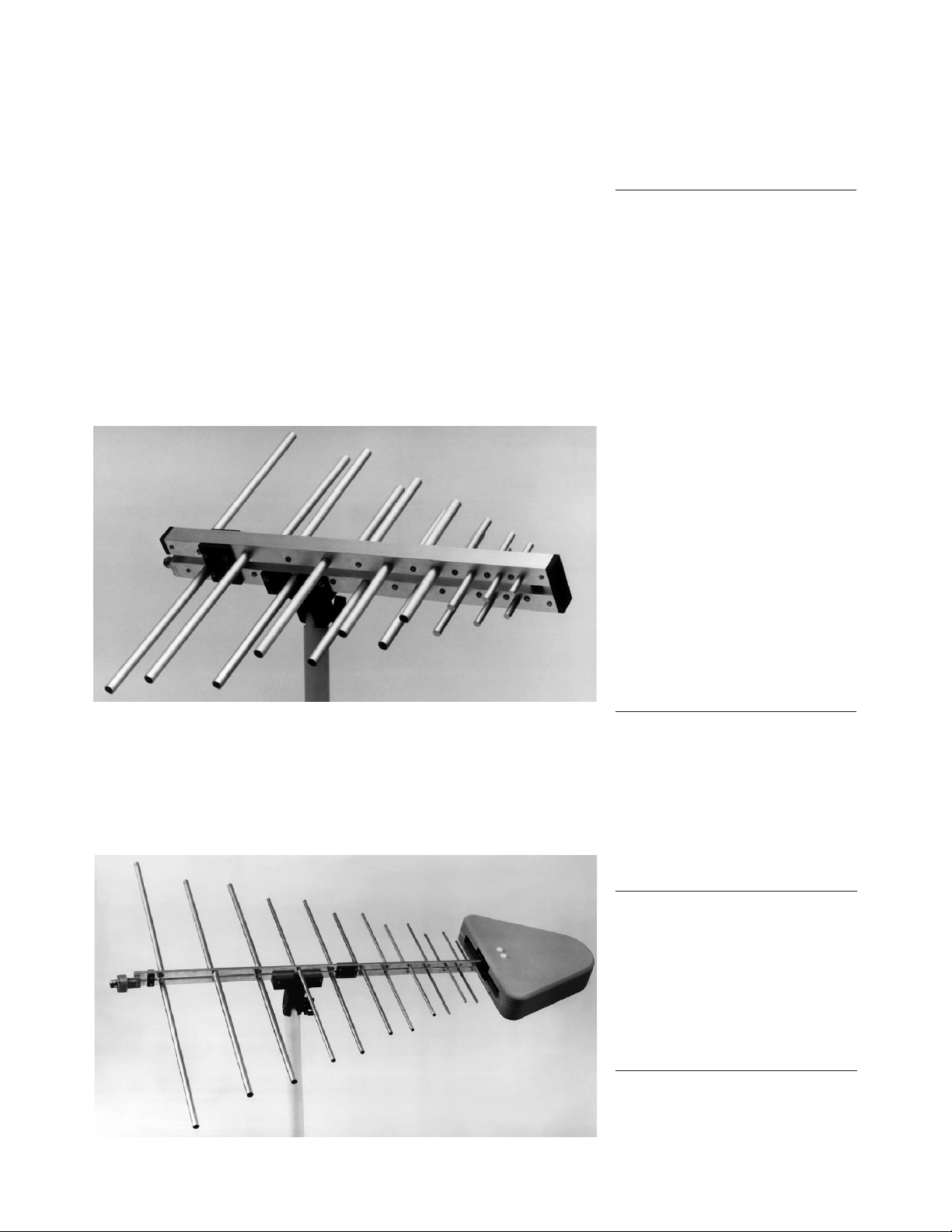
Agilent 11966D
Log Periodic Antenna
The 11966D is a broadband, relatively
high-gain antenna that is suitable for
both commercial and military EMC
measurements.
Agilent 11966N Log Periodic Antenna
This antenna has similar performance characteristics to the 11966D, but has
an extended frequency range to 5 GHz. This is useful for some of the new commerical test requirements, such as FCC part 15 limits for high-speed unintentional radiators, which now extend beyond 1 GHz.
Antennas
1
1. All antennas sold by Agilent are individually calibrated.
They include a calibration certificate showing actual
performance data. The antenna factors shown in this
catalog are intended to show typical performance
only.
 Loading...