

Page 1
1. All antennas sold by Agilent are individually calibrated.
They include a calibration certificate showing actual
performance data. The antenna factors shown in this
catalog are intended to show typical performance only.
7
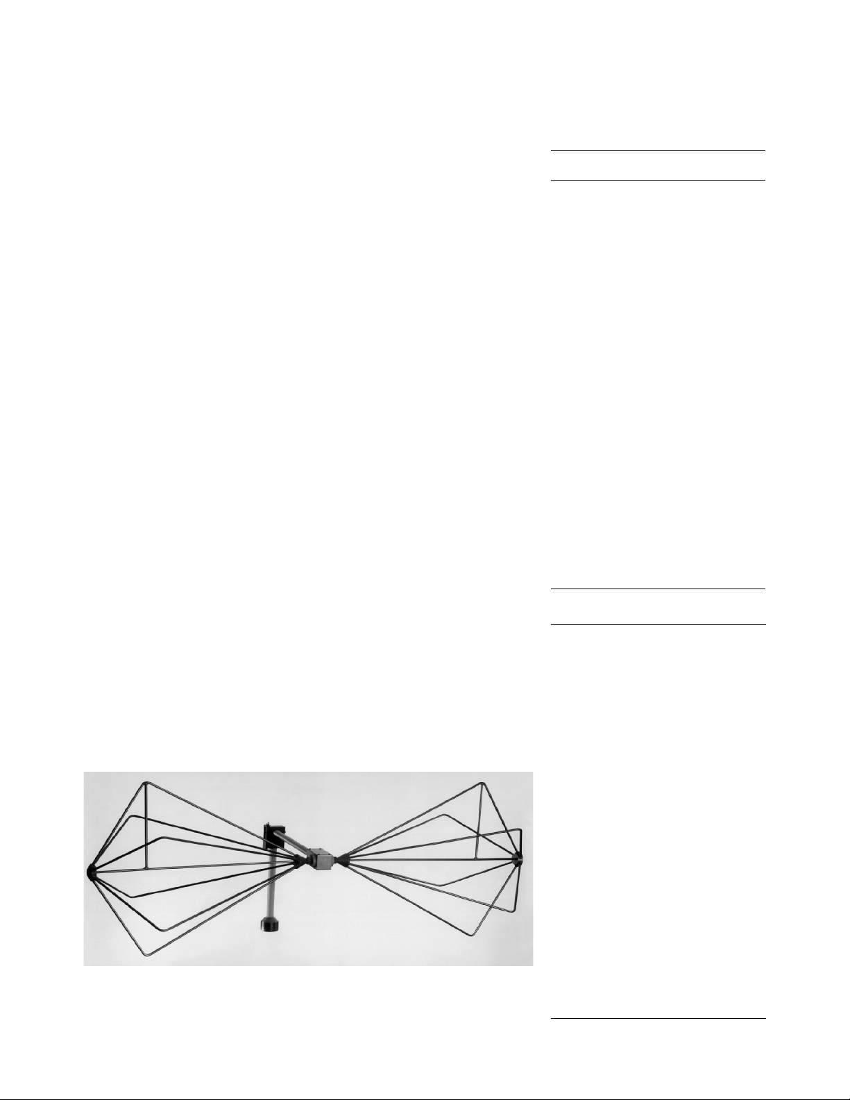
Agilent 11966A K24
Biconical Antenna
The rugged balun design of this
antenna makes it especially suitable
for susceptibility tests where high
input powers are needed.
Frequency Range 20 MHz–300 MHz
Max Contin Power 2000
VSWR (avg) 1.9 : 1
Impedance 50 Ω
Connector Type N female
Mounting Base 1/4 inch x 20 female
thread
Agilent 11966A K38
Biconical Antenna
This versatile antenna is useful for
both emissions and immunity measurements and can handle up to
300 watts of continuous power.
Frequency Range 30 MHz–300 MHz
Max Contin Power 300 W
VSWR (avg) < 2.5 : 1
Impedance 50 Ω
Connector Type N female
Mounting Base 1/4 inch x 20 female
thread
11966A K24 11966A K38
Frequency Antenna Factors
(MHz) (dB)
20 11.5 —
30 13.0 13.5
40 14.7 15
50 12.2 12.7
60 10.1 10.4
70 8.9 8.9
80 8.0 8.5
90 8.9 8.8
100 9.6 9.6
110 11.3 11.3
120 12.8 12.6
130 14.5 14.1
140 15.9 16.0
150 16.5 16.6
160 16.0 16.5
170 15.3 15.6
180 14.5 14.8
190 14.5 14.5
200 13.8 14.1
210 14.0 14.1
220 14.5 14.4
230 15.8 15.8
240 16.8 17.0
250 18.3 18.9
260 19.9 20.3
270 21.4 22.0
280 22.6 23.1
290 20.9 21.0
300 24.6 22.7
Frequency Range 30 MHz–300 MHz
Max Contin Power 0.5 W
VSWR (avg) < 1.8 : 1 (with 6 db pads)
Impedance 50 Ω
Connector Type N female
Mounting Base 1/4 inch x 20 female
thread
Frequency Typical Antenna Factor
(MHz) (dB)
30 19.0
40 17.9
50 13.2
60 9.0
70 6.6
80 7.6
90 9.2
100 10.5
110 12.0
120 14.0
130 16.3
140 18.4
150 19.4
160 19 0
170 18.3
180 17.6
190 17.0
200 16.7
210 17.0
220 17.4
230 18.2
240 19.1
250 20.4
260 22.4
270 24.5
280 25.5
290 25.0
300 24.9
Agilent 11955A
Biconical Antenna
This economical antenna has typical
antenna factors.
Frequency Range 30 MHz–300 MHz
Max Contin Power 0.5 W
VSWR (avg) 1.8 : 1
Impedance 50 Ω
Connector Type N female
Mounting Base 1/4 inch x 20 female
thread
Agilent 11966C
Biconical Antenna
This state-of-the-art antenna uses ferrites in the balun and along the feedline to eliminate common-mode currents. It employs a novel element-cage
design that allows an extremely
smooth response curve.
Antennas
1
 Loading...