

Page 1
The Agilent Technologies 8902A measuring receiver
delivers the accuracy and resolution of a high performance power meter at frequencies from 150 kHz
to 1.3 GHz (50 MHz to 26.5 GHz with the Agilent
11793A microwave converter) and levels from
+30 dBm to –127 dBm. It accurately measures AM,
FM, and fM, including residuals and incidentals,
with a single keystroke. The 8902A measuring
receiver, with the 11793A, counts RF signals to
26.5 GHz with 10 Hz resolution and excellent longterm frequency stability. The 8902A measuring
receiver with Option 050 offers increased power
measurement accuracy. This option specifies Tuned
RF Level on the 8902A measuring receiver to an
accuracy of ±(0.015 dB + 0.005 dB/10 dB step).
Agilent 8902A
Measuring Receiver
Technical Specifications
Agilent 11722A Sensor Module
Agilent 11792A Sensor Module
Agilent 11793A Microwave Converter
Agilent 11812A Verification Kit
Data sheet supplied by:
Page 2

2
AGILENT 8902A MEASURING RECEIVER*
TECHNICAL SPECIFICATIONS
Specifications describe the test set’s warranted performance
and are valid over the entire operation and environmental
ranges unless otherwise noted. All specifications are valid
after a 30-minute warm-up period of continuous operation, and within the frequency ranges defined below.
Supplemental characteristics are intended to provide
additional information useful in applying the instrument by giving typical, but non-warranted performance
parameters. These characteristics are shown in Italics
and labeled as “nominal,” “typical,” or “supplemental.”
* Shaded text signifies measurements made with the
8902A measuring receiver using the 11793A microwave
converter and 11792A sensor module. With this configuration, all standard 8902A specifications apply except
where changes are shown as shaded text.
Frequency Modulation
RATES1:
20 Hz to 10 kHz, 150 kHz ≤ f
c
<10 MHz.
20 Hz to 200 kHz, 10 MHz ≤ f
c
≤1300 MHz.
20 Hz to 200 kHz, 10 MHz ≤ f
c
≤26.5 GHz.
DEVIATIONS
1
:
40 kHz
peak
maximum, 150 kHz ≤ f
c
<10 MHz.
400 kHz
peak
maximum, 10 MHz ≤ fc≤1300 MHz.
400 kHz
peak
maximum, 10 MHz ≤ fc≤26.5 GHz.
ACCURACY
1, 2, 3
:
FM Accuracy Frequency Range Rates Deviations
±2% of reading 250 kHz – 10 MHz 20 Hz – 10 kHz ≤40 kHz
peak
±1 digit
±1% of reading 10 MHz – 1300 MHz 50 Hz – 100 kHz ≤400 kHz
peak
±1 digit
±5% of reading 10 MHz – 1300 MHz 20 Hz – 200 kHz ≤400 kHz
peak
±1 digit
±1% of reading 10 MHz – 26.5 GHz 50 Hz – 100 kHz ≤400 kHz
peak
±1 digit
±5% of reading 10 MHz – 26.5 GHz 20 Hz – 200 kHz ≤400 kHz
peak
±1 digit
For rms detector add ±3% of reading.
DEMODULATED OUTPUT DISTORTION
1, 4
:
THD Frequency Range Rates Deviations
<0.1% 400 kHz – 10 MHz 20 Hz – 10 kHz <10 kHz
<0.1% 10 MHz – 1300 MHz 20 Hz – 100 kHz <100 kHz
<0.1% 10 MHz – 26.5 GHz 20 Hz – 100 kHz <100 kHz
AM REJECTION (50 Hz to 3 kHz BW)3:
AM Rejection Frequency Range Rates AM Depths
<20 Hz peak 150 kHz – 1300 MHz 400 Hz or 1 kHz ≤50%
deviation
<20 Hz peak 150 kHz – 26.5 GHz 400 Hz or 1 kHz ≤50%
deviation
RESIDUAL FM (50 Hz to 3 kHz BW):
<8 Hz
rms
at 1300 MHz, decreasing linearly with
frequency to <1 Hz
rms
for 100 MHz and below.
<17 Hz
rms'
1300 MHz <f
c
≤6.2 GHz.
<33 Hz
rms'
6.2 GHz <f
c
≤12.4 GHz.
<49 Hz
rms'
12.4 GHz <f
c
≤18.6 GHz.
<65 Hz
rms'
18.6 GHz <f
c
≤26.5 GHz.
Supplemental Characteristics:
MAXIMUM FM DEVIATION, RESOLUTION, AND
MAXIMUM DEMODULATED OUTPUT SENSITIVITY
ACROSS AN OPEN CIRCUIT (600 Ω output impedance)
5
:
Maximum Maximum Demodulated Deviations
Resolution Output Sensitivity (DF)
100 Hz 0.01 mV/Hz DF
peak
≥ 40 kHz
10 Hz 0.1 mV/Hz 4.0 kHz ≤
DF
peak
<40 kHz
1 Hz 1.0 mV/Hz DF
peak
< 4 kHz
0.1 Hz 1.0 mV/ Hz DF
rms
< 0.3 kHz
(rms detector only)
Resolution is increased one digit with 750 µs de-emphasis and pre-display on.
The demodulated output signal present at the
Modulation Out/Audio In connector is increased in
amplitude by a factor of 10 with 750 µs de-emphasis.
DEMODULATED OUTPUT DISTORTION
1, 4
:
THD Frequency Range Rates Deviations
<0.3% 150 kHz – 400 kHz 20 Hz – 10 kHz <10 kHz
<0.1% 400 kHz – 10 MHz 20 Hz – 10 kHz <10 kHz
<0.1% 10 MHz – 26.5 GHz 20 Hz – 100 kHz <100 kHz
DETECTORS: +peak, – peak, ±peak/2, peak hold, average (rms
sinewave calibrated), rms.
STEREO SEPARATION (50 Hz to 15 kHz): >47 dB.
1. But not to exceed: 20 kHz rates and 40 kHz peak deviations with 750 µs deemphasis filter.
2. Not to exceed for stated accuracy: 50 Hz to 40 kHz rates with rms detector.
3. Peak residuals must be accounted for in peak readings.
4. With 750 µs de-emphasis and pre-display "off," distortion is not specified for
modulation outputs >4V peak. This condition can occur near maximum deviation
for a measurement range, at rates <2 kHz.
5. For optimum flatness, cables should be terminated with their characteristic
impedance.
Page 3
3
150 kHz ≤f
c
<10 MHz
Amplitude Modulation
RATES:
20 Hz to 10 kHz, 150 kHz ≤f
c
<10 MHz.
20 Hz to 100 kHz, 10 MHz ≤f
c
≤1300 MHz.
DEPTH: to 99%.
ACCURACY
2, 3, 6
:
AM Accuracy Frequency Range Rates Depths
±2% of reading 150 kHz – 10 MHz 50 Hz – 10 kHz 5% – 99%
±1 digit
±3% of reading 150 kHz – 10 MHz 20 Hz – 10 kHz to 99%
±1 digit
±1% of reading 10 MHz – 1300 MHz 50 Hz – 50 kHz 5% – 99%
±1 digit
±3% of reading 10 MHz – 1300 MHz 20 Hz – 100 kHz to 99%
±1 digit
±1.5% of reading 1300 MHz – 26.5 GHz 50 Hz – 50 kHz 5% – 99%
±1 digit
±3% of reading 10 MHz – 26.5 GHz 20 Hz – 100 kHz to 99%
±1 digit
For rms detector add ±3% of reading.
FLATNESS
5, 7
:
Flatness Frequency Range Rates Depths
±0.3% of reading 10 MHz – 1300 MHz 90 Hz – 10 kHz 20% – 80%
±1 digit
±0.3% of reading 10 MHz – 26.5 GHz 90 Hz – 10 kHz 20% – 80%
±1 digit
DEMODULATED OUTPUT DISTORTION:
<0.3% THD for ≤50% depth.
<0.6% THD for ≤95% depth.
For f
c
>1300 MHz add 0.4% THD.
FM REJECTION (50 Hz to 3 kHz BW)
3
:
FM Rejection Frequency Range Rates Deviations
<0.2% AM 250 kHz – 10 MHz 400 Hz or 1 kHz <5 kHz
peak
<0.2% AM 10 MHz – 1300 MHz 400 Hz or 1 kHz <50 kHz
peak
<0.2% AM 10 MHz – 26.5 GHz 400 Hz or 1 kHz <50 kHz
peak
RESIDUAL AM (50 Hz to 3 kHz BW): <0.01%
rms
.
Supplemental Characteristics:
DETECTORS: +peak, –peak, ±peak/2, peak hold, average (rms
sinewave calibrated), rms.
MAXIMUM DEPTH, RESOLUTION, AND MAXIMUM DEMODULATED OUTPUT SENSITIVITY ACROSS AN OPEN CIRCUIT
(600 Ω output impedance)
5
:
Maximum Maximum Demodulated Depths
Resolution Output Sensitivity
0.1% 0.01V / percent AM
peak
≥40.0%
0.01% 0.1V / percent AM
peak
<40.0%
0.001%
(rms detector only) 0.1V / percent AM
rms
<3.0%
Phase Modulation
RATES:
200 Hz to 10 kHz, 150 kHz ≤f
c
<10 MHz.
200 Hz to 20 kHz, 10 MHz ≤f
c
≤1300 MHz.
200 Hz to 20 kHz, 10 MHz ≤f
c
≤26.5 GHz.
ACCURACY
3
:
±4% of reading ±1 digit, 150 kHz ≤f
c
<10 MHz.
±3% of reading ±1 digit, 10 MHz ≤f
c
≤1300 MHz.
±3% of reading ±1 digit, 10 MHz ≤f
c
≤26.5 GHz.
For rms detector add ±3% of reading.
DEMODULATED OUTPUT DISTORTION: <0.1% THD.
AM REJECTION (for 50% AM at 1 kHz rate)
3
:
<0.03 radians peak (50 Hz to 3 kHz BW).
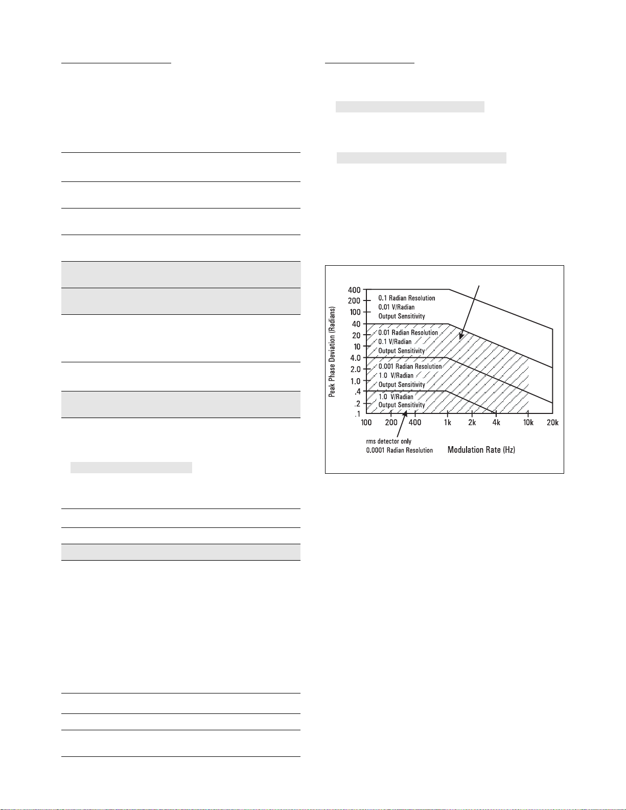
MAXIMUM DEVIATION, RESOLUTION, AND MAXIMUM
DEMODULATED OUTPUT SENSITIVITY ACROSS AN OPEN
CIRCUIT (600 Ω output impedance)
5
:
Supplemental Characteristics:
MODULATION RATES: usable from 20 Hz to 100 kHz with degraded
performance.
DETECTORS: +peak, – peak, ±peak/2, peak hold, average (rms
sinewave calibrated), rms.
2. Not to exceed for stated accuracy: 50 Hz to 40 kHz rates with rms detector.
3. Peak residuals must be accounted for in peak readings.
5. For optimum flatness, cables should be terminated with their characteristic
impedance.
6. For peak measurements only: AM accuracy may be affected by distortion generated by the measuring receiver. In the worst case this distortion can decrease accuracy by 0.1% of reading for each 0.1% of distortion.
7. Flatness is the variation in indicated AM depth for constant depth on input signal.
Page 4

4
Modulation Reference
AM CALIBRATOR DEPTH AND ACCURACY:
33.33% depth nominal, internally calibrated to an accuracy of ±0.1%.
FM CALIBRATOR DEVIATION AND ACCURACY:
34 kHz
peak
deviation nominal, internally calibrated to an accuracy
of ±0.1%.
Supplemental Characteristics:
CARRIER FREQUENCY: 10.1 MHz.
MODULATION RATE: 10 kHz.
OUTPUT LEVEL: – 25 dBm.
Frequency Counter
RANGE:
150 kHz to 1300 MHz.
150 kHz to 26.5 GHz.
SENSITIVITY:
12 mV
rms
(–25 dBm), 150 kHz ≤fc≤650 MHz.
22 mV
rms
(–20 dBm), 650 MHz ≤fc≤1300 MHz.
40 mV
rms
(–15 dBm), 150 kHz ≤fc≤650 MHz.
71 mV
rms
(–10 dBm), 650 MHz <f
c
≤1300 MHz.
40 mV
rms
(–15 dBm), 1300 MHz <f
c
≤26.5 GHz.
MAXIMUM RESOLUTION:
1 Hz.
10 Hz.
ACCURACY:
± reference accuracy ± 3 counts of least-significant digit,
f
c
<100 MHz.
± reference accuracy ± 3 counts of least-significant digit, or
30 Hz, whichever is larger, f
c
≥100 MHz.
Supplemental Characteristics:
MODES: Frequency and Frequency Error (displays the difference
between the frequency entered via the keyboard and the actual RF
input frequency).
SENSITIVITY IN MANUAL TUNING MODE:
Approximate frequency must be entered from keyboard.
0.22 mV
rms
(–60 dBm).
0.71 mV
rms
(–50 dBm).
Using the RF amplifier and the IF amplifiers, sensitivity can be
increased to approximately:
–100 dBm.
–90 dBm, f
c
≤1300 MHz.
–75 dBm, 1300 MHz <f
c
≤26.5 GHz.
8. After 30-day warm-up.
9. The 8902A fundamental RF power measurement units are watts. Further internal
processing is done on this number to display all other units.
10. When using a power sensor, the noise specification may mask the linearity specification and become the predominant error. When operating on the top RF power
range, add the power sensor's linearity percentages found in the power sensor's
specifications.
Internal Time Base Reference
FREQUENCY: 10 MHz.
AGING RATE:
<1 x 10
–6
/month.
<1 x 10
–9
/day (Option 002)8.
Supplemental Characteristics:
INTERNAL REFERENCE ACCURACY:
Overall accuracy is a function of timebase calibration, aging rate,
temperature effects, line voltage effects, and short-term stability.
Standard Option 002
Aging Rate <1 x 10⁻⁶/mo. <1 x 10⁻⁹/day
Temperature Effects <2 x 10⁻⁷/°C <2 x 10
–10
/°C
Line Voltage Effects
(+5%, –10% Line <1 x 10
–6
<6 x 10
–10
Voltage Change)
Short-Term Stability — <1 x 10⁻⁹for
1 second average
RF Power
The Agilent 8902A measuring receiver, with
11722A sensor module, performs RF power measurements from –20 dBm (10 µW) to +30 dBm (1 W)
at frequencies from 100 kHz to 2.6 GHz.
The 8902A measuring receiver, with 11792A sensor
module, performs RF power measurements from
–20 dBm (10 µW) to +30 dBm (1 W) at frequencies
from 50 MHz to 26.5 GHz.
RF POWER RESOLUTION9:
0.01% of full scale in watts or volts mode.
0.01 dB in dBm or dB
relative
mode.
LINEARITY (includes sensor non-linearity):
RF range linearity ± RF range-to-range change error.
RF RANGE LINEARITY (using recorder output)
10
:
±0.02 dB, RF ranges 2 through 5.
±0.03 dB, RF range 1.
Using front-panel display add ±1 count of least-significant digit.
RF RANGE-TO-RANGE CHANGE ERROR (using recorder output):
±0.02 dB/RF range change from reference range.
Using front-panel display add ±1 count of least-significant digit.
INPUT SWR:
Using 11722A sensor module: <1.15.
Using 11792A sensor module:
<1.15, 1300 MHz ≤f
c
.
<1.25, 1300 MHz <f
c
≤18.0 GHz.
<1.40, 18.0 GHz <f
c
≤26.5 GHz.
Page 5

5
ZERO SET (digital settability of zero):
±0.07% of full scale on lowest range.
Decrease by a factor of 10 for each higher range.
Supplemental Characteristics:
ZERO DRIFT OF METER:
±0.03% of full scale/°C on lowest range. Decrease by a
factor of 10 for each higher range.
NOISE (at constant temperature, peak change over any oneminute interval for the 11722A or 11792A sensor modules):
0.4% of full scale on range 1 (lowest range).
0.13% of full scale on range 2.
0.013% of full scale on range 3.
0.0013% of full scale on range 4.
0.00013% of full scale on range 5.
ZERO DRIFT OF SENSORS (1 hour, at constant temperature after
24-hour warm-up):
±0.1% of full scale on lowest range for 11722A
and 11792A sensor modules.
RF POWER RANGES OF AGILENT 8902A MEASURING RECEIVER
WITH 11722A AND 11792A SENSOR MODULES:
–20 dBm to –10 dBm (10 µW to 100 µW), range 1.
–10 dBm to 0 dBm (100 µW to 1 mW), range 2.
0 dBm to +10 dBm (1 mW to 10 mW), range 3.
+10 dBm to +20 dBm (10 mW to 100 mW), range 4.
+20 dBm to +30 dBm (100 mW to 1 W), range 5.
RESPONSE TIME (0 to 99% of reading):
<10 seconds, range 1.
<1 second, range 2.
<100 milliseconds, ranges 3 through 5.
DISPLAYED UNITS:
Watts, dBm, dB
relative
, %
relative
, volts, mV, µV, dB V, dB mV, dB µV.
INTERNAL NON-VOLATILE CAL-FACTOR TABLES
(user-modifiable using special functions):
Maximum number of cal factor/frequency entries:
Table #1 (primary): 16 pairs plus Reference Cal Factor.
Table #2 (frequency offset): 22 pairs plus Reference Cal Factor.
Maximum Allowed Frequency Entry: 42 GHz.
Frequency Entry Resolution: 50 kHz.
Cal Factor Range: 40 to 120%.
Cal Factor Resolution: 0.1%.
Power Reference
POWER OUTPUT:
1.00 mW. Factory set to ±0.7%, traceable to the U.S. National
Bureau of Standards.
ACCURACY: ±1.2% worst case (±0.9% rss) for one year (0 °C to
55 °C).
Supplemental Characteristics:
FREQUENCY: 50 MHz nominal.
SWR: 1.05 nominal.
FRONT PANEL CONNECTOR: N-type female.
Tuned RF Level
POWER RANGE: –127 dBm to 0 dBm, using IF synchronous detector
(200 Hz BW).
–100 dBm to 0 dBm, using IF average detector (30 kHz BW).
POWER RANGE (Using 11792A Sensor Module):
For IF Synchronous Detector:
+10 dBm to –117 dBm, 2.5 MHz ≤f
c
≤1300 MHz.
+5 dBm to –105 dBm, 1300 MHz ≤f
c
≤12.4 GHz.
+5 dBm to –100 dBm, 12.4 GHz ≤f
c
≤18.0 GHz.
+5 dBm to –95 dBm, 18.0 GHz ≤f
c
≤26.5 GHz.
For IF Average Detector:
+10 dBm to –90 dBm, 2.5 MHz ≤f
c
≤1300 MHz.
+5 dBm to –80 dBm, 1300 MHz ≤f
c
≤12.4 GHz.
+5 dBm to –75 dBm, 12.4 GHz ≤f
c
≤18.0 GHz.
+5 dBm to –70 dBm, 18.0 GHz ≤f
c
≤26.5 GHz.
1.9 Special Function degrades Tuned RF Level minimum
sensitivity by 10 dB.
FREQUENCY RANGE:
2.5 MHz to 1300 MHz.
2.5 MHz to 26.5 GHz.
DISPLAYED RESOLUTION
11
:
4 digits in watts or volts mode.
0.01 dB or 0.001 dB in dBm or dB
relative
mode.
4 digits in watts or volts mode.
0.01 dB in dBm or dB
relative
mode.
RELATIVE MEASUREMENT ACCURACY (at constant temperature
and after RF range calibration is completed)
12
:
Detector linearity + IF range-to-range error + RF range-to-range
error + frequency drift error + noise error ± 1 digit.
Detector linearity + mixer linearity + IF range-to-range error + RF
range-to-range error + frequency drift error + noise error ± 1 digit.
11. The 8902A fundamental Tuned RF Level measurement units are volts. Further
internal processing is done on this number to display all other units.
12. Tuned RF Level accuracy will be affected by residual FM of the source-under-test.
If the residual FM
peak
is >50 Hz measured over a 30 second period in a 3 kHz BW.
Tuned RF Level measurements should be made using the IF average detector (30
kHz BW) by using Special Function 4.4. The Tuned RF Level measurement sensitivity when using the IF average detector is –100 dBm.
Page 6

6
DETECTOR LINEARITY:
For IF Synchronous Detector:
±0.007 dB/dB change, but not more than
±0.02 dB/10 dB change.
Typically <±0.004 dB/dB change and
<±0.01 dB/10 dB change.
For IF Average Detector (0 °C to +35 °C):
±0.013 dB/dB change,
but not more than±0.04 dB/10 dB change,
but not more than ±0.06 dB/10 dB change.
Typically <±0.008 dB/dB change and
<±0.02 dB/10 dB change.
MIXER LINEARITY:
Negligible, levels ≤–5 dBm.
±0.04 dB, levels >–5 dBm and frequencies >1300 MHz.
IF RANGE-TO-RANGE ERROR (see Tuned RF Level range plot)
13
:
±0.02 dB/IF range change, IF ranges 1 through 5.
±0.05 dB/IF range change, IF ranges 6 through 7.
RF RANGE-TO-RANGE ERROR:
±0.04 dB/IF range change (Tuned RF Level only).
±0.06 dB/IF range change, RF Power to Tuned RF Level.
FREQUENCY DRIFT ERROR: ±0.05 dB/kHz frequency drift from
center of IF (using IF synchronous detector).
NOISE ERROR: ±0.18 dB for levels <–120 dBm, or for levels
<–110 dBm if Special Function 1.9 is selected.
±0.18 dB, levels <–110 dBm, 2.5 MHz ≤f
c
≤1300 MHz.
±0.18 dB, levels <–98 dBm, 1300 MHz ≤f
c
≤12.4 GHz.
±0.18 dB, levels <–93 dBm, 12.4 GHz ≤f
c
≤18.0 GHz.
±0.18 dB, levels <–88 dBm, 18.0 GHz ≤f
c
≤26.5 GHz.
Negligible elsewhere.
INPUT SWR:
<1.18, at 8902A RF input, RF range 1 and 2.
<1.40, at 8902A RF input, RF range 3.
<1.33, at 11722A RF input, RF range 1 and 2.
<1.50, at 11722A RF input, RF range 3.
<1.33, at 11722A RF input, RF range 3 with Special
Function 1.9.
Using 11792A sensor module:
<1.15, 1300 MHz ≤f
c.
<1.25, 1300 MHz ≤fc≤18.0 GHz.
<1.40, 18.0 GHz ≤f
c
≤26.5 GHz.
Supplemental Characteristics:
ABSOLUTE LEVEL MEASUREMENT ACCURACY AT LOW LEVELS
(at constant temperature and after RF range calibration is completed)
12
:
Absolute level measurement accuracy is a function of the RF
Power and Tuned RF Level measurement accuracy. For a source
with an output SWR of 1.7 and level of –110 dBm the typical
absolute level measurement accuracy is 0.46 dB rss and 1.02 dB
worst case.
IF FREQUENCY: 455 kHz.
ACQUISITION TIME:
<4 seconds, ≥–110 dBm.
<10 seconds, ≥–127 dBm.
<4 seconds, levels ≥–85 dBm.
<10 seconds, levels <–85 dBm.
RESPONSE TIME (responding to changes in level of an acquired
signal):
<2 seconds, ≥–110 dBm.
<5 seconds, ≥–127 dBm.
<2 seconds, ≥–85 dBm.
<5 seconds, <–85 dBm.
DISPLAYED UNITS: Watts, dBm, dB
relative
, %
relative
, volts, mV, µV,
dB V, dB mV, dB µV.
12. Tuned RF Level accuracy will be affected by residual FM of the source-under-test.
If the residual FMpeak is >50 Hz measured over a 30 second period in a 3 kHz
BW, Tuned RF Level measurements should be made using the IF average detector
(30 kHz BW) by using Special Function 4.4. The Tuned RF Level measurement sensitivity when using the IF average detector is –100 dBm.
13. IF Ranges 6 and 7 (see Tuned RF Level range plots) are only used in automatic
operation for Tuned RF Level measurements below approximately –110 dBm for
the IF synchronous detector, and below approximately –85 dBm for the IF average
detector.
13
Page 7

Carrier Noise (Options 030-037)
FREQUENCY RANGE: 10 MHz to 1300 MHz.
CARRIER POWER RANGE: +30 dBm to –20 dBm;
12.5 kHz, 25 kHz and 30 kHz filters.
+30 dBm to –10 dBm; carrier noise filter.
DYNAMIC RANGE: 115 dB.
CARRIER REJECTION (temp. ≤35 °C): >90 dB; for offsets of at
least 1 channel spacing or 5 kHz, whichever is greater.
RELATIVE MEASUREMENT ACCURACY:
±0.5 dB; levels ≥–95 dBc; 12.5 kHz, 25 kHz and
30 kHz filters.
±0.5 dB; levels ≥–129 dBc/Hz; carrier noise filter.
CARRIER NOISE FILTER:
Filter Noise Bandwidth: 2.5 kHz nominal.
Noise Bandwidth Correction Accuracy (stored in non-volatile
memory): ±0.2 dB.
Supplemental Characteristics:
ADJACENT/ALTERNATE CHANNEL FILTERS:
6 dB Filter Bandwidth:
8.5 kHz, 12.5 kHz adjacent-channel filter.
16.0 kHz, 25 kHz adjacent-channel filter.
30.0 kHz, 30 kHz (cellular radio) alternate-channel filter.
TYPICAL NOISE FLOOR: –150 dBc/Hz, 0 dBm carrier power level.
For system noise performance add LO contribution.
14. With the low-pass and high-pass audio filters used to stabilize frequency readings.
Audio Frequency Counter
FREQUENCY RANGE:
20 Hz to 250 kHz. (Usable to 600 kHz.)
MAXIMUM EXTERNAL INPUT VOLTAGE: 3V
rms
.
ACCURACY (for demodulated signals)
14
:
Accuracy Frequency Modulation (Peak)
±3 counts of least-significant digit >1 kHz AM ≥10%
±Internal Reference Accuracy FM ≥1.0 kHz
fM≥1.5 radians
±0.02 Hz ≤1 kHz AM≥10%
±Internal Reference Accuracy FM≥1.0 kHz
fM≥1.5 radians
±0.2 Hz ≤3 kHz 1.5%≤AM<10%
±Internal Reference Accuracy 0.15 kHz≤FM
(3 kHz low-pass filter inserted) <1.0 kHz
0.15 radian≤fM
<1.5 radians
ACCURACY (for external signals)
14
:
Accuracy Frequency Level
±3 counts of least-significant digit >1 kHz ≥100 mV
rms
±Internal Reference
±0.02 Hz ≤1 kHz ≥100 mV
rms
±Internal Reference Accuracy
Supplemental Characteristics:
DISPLAYED RESOLUTION: 6 digits.
MEASUREMENT RATE: 2 readings per second.
COUNTING TECHNIQUE: Reciprocal with internal 10 MHz timebase.
AUDIO INPUT IMPEDANCE: 100 kΩ nominal.
Audio RMS Level
FREQUENCY RANGE: 50 Hz to 40 kHz.
VOLTAGE RANGE: 100 mV to 3 V.
ACCURACY: ± 4.0% of reading.
Supplemental Characteristics:
FULL RANGE DISPLAY: 0.3000 V, 4.000 V.
AC CONVERTER: True-rms responding for signals with crest factor
of ≤ 3.
MEASUREMENT RATE: 2 readings per second.
AUDIO INPUT IMPEDANCE: 100 kΩ nominal.
7
Page 8

8
Audio Distortion
FUNDAMENTAL FREQUENCIES: 400 Hz ±5% and 1 kHz ±5%.
MAXIMUM EXTERNAL INPUT VOLTAGE: 3 V.
DISPLAY RANGE: 0.01% to 100.0% (–80.00 dB to 0.00 dB).
DISPLAYED RESOLUTION: 0.01% or 0.01 dB.
ACCURACY: ±1 dB of reading.
SENSITIVITY:
Modulation: 0.15 kHz peak FM, 1.5% peak AM or
0.6 radian peak fM.
External: 100 mV
rms
.
RESIDUAL NOISE AND DISTORTION
15
:
0.3% ( –50 dB), temperature <40 °C.
Supplemental Characteristics:
MEASUREMENT 3 dB BANDWIDTH: 20 Hz to 50 kHz.
DETECTION: True rms.
MEASUREMENT RATE: 1 reading per second.
AUDIO INPUT IMPEDANCE: 100 kΩ nominal.
Audio Filters
DE-EMPHASIS FILTERS: 25 ms, 50 ms, 75 ms, and 750 ms. De-
emphasis filters are single-pole, low-pass filters with 3 dB frequencies of: 6366 Hz for 25 ms, 3183 Hz for 50 ms, 2122 Hz for 75 ms,
and 212 Hz for 750 ms.
50 Hz HIGH-PASS FILTER (2 pole):
Flatness: <1% at rates ≥200 Hz.
300 Hz HIGH-PASS FILTER (2 pole):
Flatness: <1% at rates ≥1 kHz.
3 kHz LOW-PASS FILTER (5 pole):
Flatness: <1% at rates ≤1 kHz.
15 kHz LOW-PASS FILTER (5 pole):
Flatness: <1% at rates ≤10 kHz.
>20 kHz LOW-PASS FILTER (9 pole bessel)
16
:
Flatness: <1% at rates ≤10 kHz.
Supplemental Characteristics:
DE-EMPHASIS FILTER TIME CONSTANT ACCURACY: ±3%.
HIGH PASS AND LOW PASS FILTER 3 dB CUTOFF FREQUENCY
ACCURACY: ±3%.
>20 kHz LOW PASS FILTER 3 dB CUTOFF FREQUENCY:
100 kHz nominal.
OVERSHOOT ON SQUARE WAVE MODULATION16: <1%.
RF Input
FREQUENCY RANGE: 150 kHz to 1300 MHz.
150 kHz to 26.5 GHz when using the 11793A sensor module.
OPERATING LEVEL:
Minimum Maximum Frequency Range
Operating Level Operating Level
12 mV
rms
(–25 dBm) 7 V
rms
(1 W
peak
) 150 kHz – 650 MHz
Source SWR <4
22 mV
rms
(–20 dBm) 7 V
rms
(1 W
peak
) 650 MHz – 1300 MHz
Source SWR <4
40 mV
rms
(–15 dBm) 7V
rms
(1 W
peak
) 150 kHz – 650 MHz
71 mV
rms
(–10 dBm) 7V
rms
(1 W
peak
) 650 MHz – 1300 MHz
40 mV
rms
(–15 dBm) 7V
rms
(1 W
peak
) 1300 MHz – 26.5 GHz
Supplemental Characteristics:
TUNING:
Normal Mode: Automatic and manual frequency entry.
Track Mode: Automatic and manual frequency entry, f
c
≥ 10 MHz.
Normal and Track Mode: Manual entry of approximate frequency.
Acquisition Time (automatic operation): ~1.5 seconds.
INPUT IMPEDANCE: 50 Ω nominal.
MAXIMUM SAFE DC INPUT LEVEL: 5 V dc.
General Specifications
TEMPERATURE:
Operating: 0 °C to 55 °C.
Storage: – 55 °C to 75 °C.
REMOTE OPERATION: GPIB; all functions except the line switch
are remotely controllable.
DEFINED IN IEEE-488.2 GPIB COMPATIBILITY: SH1, AH1, T5, TE0,
L3, LE0, SR1, RL1, PP0, DC1, DT1, C0, E1.
EMI: Conducted and radiated interference is within the requirements of VDE 0871 (Level B), and CISPR publication 11.
POWER: 100, 120, 220, or 240V (+5%, –10%); 48 to 66 Hz; 200 VA
maximum.
WEIGHT: Net 23.4 kg (52 lb); Shipping 31.4 kg (69 lb).
DIMENSIONS: 190 mm H x 426 mm W x 551 mm D
(7.5" x 16.8" x 21.7").
15. For demodulated signals, the residual noise generated by the 8902A must be
accounted for in distortion measurements (that is residual AM, FM or fM).
16. The >20 kHz low-pass filter is intended for minimum overshoot with squarewave
modulation.
Page 9

9
OPTION 050 SPECIFICATIONS
FREQUENCY RANGE: 2.5 MHz to 26.5 GHz.
TUNED RF LEVEL DYNAMIC RANGE:
–120 dBm to 0 dBm.
–110 dBm to –15 dBm.
POWER ACCURACY:
Using an Agilent 8902A Option 050 with 11722A sensor module
(10 to 1300 MHz):
Relative accuracy:
±0.005 dB/10 dB step (0 to –100 dBm).
±0.050 dB/10 dB step (–100 to –120 dBm).
±0.015 dB ± 1 digit.
Absolute accuracy:
±0.005 dB/10 dB step (0 to –100 dBm).
±0.050 dB/10 dB step (–100 to –120 dBm).
±0.120 dB ± 1 digit.
Using an Agilent 8902A Option 050 with 11722A sensor module
and 11793A microwave converter
(1300 to 2600 MHz, –15 to –110 dBm):
Relative accuracy, 85 dB dynamic range:
±0.005 dB/10 dB step (0 to 60 dB).
±0.050 dB/10 dB step (60 to 85 dB).
±0.015 dB ± 1 digit.
Absolute accuracy:
±0.005 dB/10 dB step (–15 to –100 dBm).
±0.050 dB/10 dB step (–100 to –110 dBm).
±0.120 dB ± 1 digit.
Using an Agilent 8902A Option 050 with 11792A sensor module
and 11793A microwave converter
(1300 MHz to 26.5 GHz, –15 to –100 dBm):
Relative accuracy, 85 dB dynamic range:
±0.005 dB/10 dB step (0 to 60 dB).
±0.050 dB/10 dB step (60 to 85 dB).
±0.015 dB ± 1 digit.
Absolute accuracy:
±0.005 dB/10 dB step (–15 to –100 dBm).
±0.120 dB ± 1 digit.
INPUT SWR:
<1.18, RF range 1 and 2.
<1.40, RF range 3.
TEMPERATURE:
Operating: 15 °C to 30 °C.
Storage: –55 °C to 74 °C.
Supplemental Characteristics:
MEASUREMENT TIME:
10 to 30 seconds.
AGILENT 11793A MICROWAVE CONVERTER
SPECIFICATIONS
LO AMPLITUDE RANGE:
+8 dBm to +13 dBm, 2 GHz to 18 GHz.
+7 dBm to +13 dBm, 18 GHz to 26.5 GHz.
0 dBm to + 5 dBm, 18 GHz to 26.5 GHz with Option 001,
011, or 021.
TEMPERATURE:
Operation: 0 °C to 55 °C.
Storage: –55 °C to 75 °C.
–25 °C to 75 °C (Options 001, 011, and 021).
POWER: 100, 120, 220, or 240 (+5%, –10%); 48 to 66 Hz;
20 VA maximum.
WEIGHT: Net 7.5 kg (16.5 lb); shipping 10.9 kg (24 lb).
DIMENSIONS: 88 mm H x 425 mm W x 528 mm D.
Supplemental Characteristics:
RF INPUT CONNECTOR: 3.5 mm male.
LO INPUT CONNECTOR: 3.5 mm male.
IF OUTPUT CONNECTOR: N-type female.
REAR PANEL CONTROL CONNECTOR: BNC female.
INCLUDED ACCESSORIES:
Control Cable: 11170A BNC cable.
LO Output to 11793A LO Input Cable: 3.5 mm female to 3.5 mm
female flexible cable and 3.5 mm male to N-type male adapter;
Options 001, 011, and 021 delete the 3.5 mm to N-type adapter.
8902A RF input to 11793A IF output cable: N-type male to N-type
male flexible cable.
Page 10

10
AGILENT 11722A SENSOR MODULE
SPECIFICATIONS
FREQUENCY RANGE: 100 kHz to 2.6 GHz.
POWER RANGE: +30 dBm (1 watt) to – 20 dBm (10 mW).
INPUT SWR (connected to an 8902A):
<1.15, for RF Power measurements.
<1.33, for Tuned RF Level measurements, RF range 1 and 2.
<1.5, for Tuned RF Level measurements, RF range 3.
<1.33, for Tuned RF Level measurements, RF range 3 with
Special Function 1.9.
POWER SENSOR LINEARITY:
+2%, – 4%; +30 dBm to +20 dBm.
Negligible deviation, levels <+20 dBm.
CALIBRATION FACTORS:
Each 11722A sensor module is individually calibrated. The calibration factors are printed on the 11722A sensor module for easy reference.
CAL FACTOR UNCERTAINTY:
Frequency RSS Uncertainty Worst Case
(MHz) Uncertainty
0.1 0.7 % 1.6%
0.3 0.7% 1.6%
1.0 0.8% 1.7%
3.0 0.8% 1.7%
10.0 0.9% 2.0%
30.0 0.9% 2.0%
50.0 0.0% (ref) 0.0% (ref)
100.0 1.1% 2.2%
300.0 1.1% 2.2%
1000.0 1.1% 2.2%
2600.0 1.2% 2.3%
Supplemental Characteristics:
MAXIMUM PEAK POWER: 100 Wpeak or 300 W ms per pulse.
INPUT IMPEDANCE: 50 Ω nominal.
INPUT CONNECTOR: N-type male.
SWITCH LIFE: >1,000,000 switchings.
SWITCH ISOLATION: >90 dB.
WEIGHT: Net 0.8 kg (1.75 lb); Shipping 1.2 kg (2.6 lb).
DIMENSIONS: 51.2 mm H x 62.4 mm W x 1935 mm D
(2" x 2.5" x 76.2").
AGILENT 11792A SENSOR MODULE
SPECIFICATIONS
FREQUENCY RANGE:
RF Power measurements:
50 MHz to 26.5 GHz.
50 MHz to 18.0 GHz, Option 001.
POWER RANGE: +30 dBm (1 watt) to – 20 dBm (10 mW).
INPUT SWR (connected to an Agilent 11793A):
<1.15, 1300 MHz ≤f
c
.
<1.25, 1300 MHz <f
c
≤18.0 GHz.
<1.40, 18.0 GHz <f
c
≤26.5 GHz.
POWER SENSOR LINEARITY:
+2%, – 4%; +30 dBm to +20 dBm.
Negligible deviation, levels <+20 dBm.
CALIBRATION FACTORS:
Each 11792A sensor module is individually calibrated. The calibration factors are printed on the 11792A sensor module for easy reference.
CAL FACTOR UNCERTAINTY:
Frequency RSS Uncertainty Worst Case
Uncertainty
2.0 GHz 2.3 4.6%
6.0 GHz 2.5 5.0%
10.0 GHz
2.9 5.7%
14.0 GHz
3.4 6.6%
18.0 GHz 3.7 6.9%
22.0 GHz
3.8 7.8%
26.5 GHz 4.1 8.3%
Supplemental Characteristics:
INPUT CONNECTOR: 3.5 mm male (N-type male, Option 001).
INPUT IMPEDANCE: 50 Ω nominal.
SWITCH LIFE: >1,000,000 switchings.
WEIGHT: Net 0.8 kg (1.75 lb); Shipping 1.2 kg (2.6 lb).
DIMENSIONS: 51.2 mm H x 62.4 mm W x 1935 mm D
(2" x 2.5" x 76.2").
Page 11

11
AGILENT 11812A VERIFICATION KIT
SPECIFICATIONS
FREQUENCY: 30 MHz.
11812A ACCURACY: ±(0.003 dB + 0.003 dB/10 dB step).
OPTION 050 WORST CASE CUMULATIVE TUNED RF LEVEL
ACCURACY VERIFIED WITH 11812A:
±0.010 dB/10 dB step (0 to –100 dBm).
±0.050 dB/10 dB step (–100 to –120 dBm).
±0.015 dB ± 1 digit.
TEMPERATURE:
Operation: 15 °C to 30 °C.
Storage: –55 °C to 74 °C.
AGILENT 8902A REAR PANEL
INPUTS/OUTPUTS
Supplemental Characteristics:
FM OUTPUT: 10 kΩ impedance, –9 V to 6 V into an open circuit,
~6 V/MHz, dc coupled, 16 kHz bandwidth (one pole).
AM OUTPUT: 10 kΩ impedance, –4 V to 0 V into an open circuit,
~8 mV/%, dc coupled, 16 kHz bandwidth (one pole).
RECORDER OUTPUT: DC voltage proportional to the measured
results, 1 kΩ impedance, 0 V to 4 V for each resolution range into
an open circuit.
IF OUTPUT: 50 Ω impedance, 150 kHz to 2.5 MHz, –27 dBm to –3
dBm.
10 MHz REFERENCE OUTPUT: 50 Ω impedance, TTL levels (0 V to
>2.2 V into an open circuit). Available only with Option 002
1x10
–9
/day internal reference.
10 MHz REFERENCE INPUT
17:
>500 Ω impedance, 0.5 V
peak-to-peak
minimum input level.
LO INPUT (Option 003): 50 Ω impedance, ~1.27 MHz to 1301.5
MHz, 0 dBm nominal.
RF SWITCH REMOTE CONTROL OUTPUT: Provides output signals
necessary to remotely control either an Agilent 33311B,C Option
011 or an 8761A RF switch.
FREQUENCY OFFSET MODE REMOTE CONTROL OUTPUT: TTL
high output if in frequency offset mode (Special Function 27.1 or
27.3) with an external LO frequency >0, TTL low output for all
other cases.
17. External reference accuracy affects accuracy of all measurements.
Page 12

Agilent Technologies’ Test and Measurement
Support, Services, and Assistance
Agilent Technologies aims to maximize the value you receive,
while minimizing your risk and problems. We strive to ensure
that you get the test and measurement capabilities you paid
for and obtain the support you need. Our extensive support
resources and services can help you choose the right Agilent
products for your applications and apply them successfully.
Every instrument and system we sell has a global warranty.
Support is available for at least five years beyond the production life of the product. Two concepts underlie Agilent’s
overall support policy: “Our Promise” and “Your Advantage.”
Our Promise
“Our Promise” means your Agilent test and measurement equipment will meet its advertised performance and functionality.
When you are choosing new equipment, we will help you with
product information, including realistic performance specifications and practical recommendations from experienced test
engineers. When you use Agilent equipment, we can verify that
it works properly, help with product operation, and provide
basic measurement assistance for the use of specified capabilities, at no extra cost upon request. Many self-help tools are
available.
Your Advantage
“Your Advantage” means that Agilent offers a wide range of
additional expert test and measurement services, which you
can purchase according to your unique technical and business
needs. Solve problems efficiently and gain a competitive edge
by contracting with us for calibration, extra-cost upgrades, outof-warranty repairs, and on-site education and training, as well
as design, system integration, project management, and other
professional services. Experienced Agilent engineers and technicians worldwide can help you maximize your productivity,
optimize the return on investment of your Agilent instruments
and systems, and obtain dependable measurement accuracy
for the life of those products.
By internet, phone, or fax, get assistance with all your
test and measurement needs.
Online Assistance
www.agilent.com/find/assist
Phone or Fax
United States:
(tel) 1 800 452 4844
Canada:
(tel) 1 877 894 4414
(fax) (905) 206 4120
Europe:
(tel) (31 20) 547 2323
(fax) (31 20) 547 2390
Japan:
(tel) (81) 426 56 7832
(fax) (81) 426 56 7840
Latin America:
(tel) (305) 269 7500
(fax) (305) 269 7599
Australia:
(tel) 1 800 629 485
(fax) (61 3) 9210 5947
New Zealand:
(tel) 0 800 738 378
(fax) (64 4) 495 8950
Asia Pacific:
(tel) (852) 3197 7777
(fax) (852) 2506 9284
Product specifications and descriptions in this
document subject to change without notice.
Copyright © 1985, 2000 Agilent Technologies
Printed in U.S.A. 10/00
5968-5312E
For more information visit our website at:
www.agilent.com/find/wireless
 Loading...