

Page 1
• High accuracy
This PDF has been enabled for editing.
Even though you may only have the free
Acrobat Reader software, you can still add
comments to this PDF using the drawing
markup tools. Please DO use these
comment markup tools.
1. Where can I find the drawing markup tools?
Look under “Tools”… “Comment & Markup”...
“Show Comment and Markup Tool Bar”.
2. How can I change line weight, font, and
colors? Right click on a vacant part of the tool
bar. Click on “Properties Bar” (content will
change with each different tool).
3. Can I use the “insert text” tool? Avoid this
tool as it is hard to see. Please do not use
“sticky notes” tool
either.
Let’s save Agilent $$$! 3 drafts please
• Low SWR
• Broadband frequency
coverage
• Small size
Agilent 8491A/B, 8493A/B/C,
11581A, 11582A and 11583C
Coaxial Attenuators
Technical Overview
Page 2

Description
Agilent’s coaxial fixed attenuators
provide precision attenuation, flat
frequency response, and low SWR
over broad frequency ranges (dc to
26.5 GHz) at low prices. Attenuators
are available in eight attenuation
values: 3, 6, 10, 20, 30, 40, 50, and
60 dB; with performances specified
from dc to 26.5 GHz; and with choice
of four connector types: Type-N, SMA
and APC 3.52.
These attenuators are all tested
on a state-of-the-art precision analyzerto assure specifications over
the full frequency ranges. Although
the 8493C is not specified above
26.5 GHz, it performs resonance
free to 34 GHz with only a small
loss in performance.
Precision construction
The attenuators employ a film on
an attenuator card as the resistive
element. The uniformity and repeatability of the film deposition process
result in high accuracy and low SWR
over very wide frequency ranges.
1
,
The 8493C features thin-filmtantalumnitride on a sapphire
substrate for exceptional precision
performance to 26.5 GHz. In fact, it
performs resonance-free to 34 GHz,
the top frequency limit of the APC-3.5
connector.
The choice of connector type andmaterial also ensure accurate and
repeatable attenuation. The 8491A/B
attenuators are furnished with Type-N
connectors whose dimensions are
compatible with either MIL-C-71 or
MIL-C-39012 connector specifications.
These connectors are stainless
steel for long wear and high repeatability. The 8493A/B attenuators are
furnished withSMA type connectors.
The connectors are heat treated
beryllium copperfor greater strength
and wear.
Quality assurance in testing
The flat frequency response and low
SWR of the attenuators areassured
over the entire frequency range by
full frequency band testing on a stateof-the-art precision analyzer. Full
frequency band testing ensures that
narrow resonances in the frequency
band are not over-looked. Actual
attenuation values taken at dc, 4, 8,
12, 18, and 26.5GHz are stamped on
the attenuator body for permanent
and easy reference.
Testing each attenuator with a stateof-the-art precision analyzer brings
standards lab accuracy to production
testing because the system can
determine its own measurement
uncertainties and compensate for
them in the testing process. System
calibration is derived from precise
physical standards which are directly
traceable to the National Bureau of
Standards. In addition, automatic
testing eliminates the possibility of
human error in setting instrument
controls, taking data, or making
calculations.
The 8493C is furnished with theAPC
3.5 connector which is compatible
with standard SMA connectors but
is more rugged and offers improved
repeatability over hundreds of connections.
1. As per USASI Committee C83.2 compatible with OSM, ARM, WPM, BRM, NPM, etc.
2. Mate with MIL-C-71 or MIL-C-39012 connectors.
2
Page 3
Applications
Ruggedness, reliability and small
size make these attenuators useful
both on the bench and in systems
applications. With their high accuracy
and low SWR they are ideally suited
for extending the range of sensitive
power meters for higher power measurements and for “padding” poorly
matched devices to improve system
SWR.
These same characteristics lend
themselves to applications as
calibration standards in attenuation
and RF substitution measurements.
With their broad dc to 26.5 GHz
frequency range and reasonable cost,
general applications, such as the
reduction of power level to sensitive
components and instrumentation
systems, are attractive and appropriate uses for these attenuators.
Accuracy
The accuracy of an attenuator directly
affects the accuracy of the measurement where the attenuator is used. In
fact, attenuators are used extensively
as the standard against which other
instruments or devices are calibrated.
Aglilent’s fixed attenuators achieve
flat frequency response (typically a
few hundredths of a dB) and overall
accuracy (typically ±2 % of value
in dB at 26.5 GHz) through the use
of thin-film attenuator cards. These
cards are composed of high stability tantalum nitride resistive film
deposited on a sapphire or alumina
substrate.
Quality assurance in
specifications
The following examples demonstrate
the reliability and comprehensiveness
of specifications. Although the
absolute accuracy for a 3 dB attenuator is specified as ±0.3 dB, test data
statistics indicate an expected value
of 3 dB ±0.20 dB from dc to 18 GHz.
Similarly a 30 dB attenuator is specified as ±1.0 dB, but typically is no
worse than 30 dB ±0.75 dB from dc to
18 GHz. The other attenuation values
are also specified as conservatively.
In addition, Agilent precision attenuators meet more comprehensive
performance standards. Linear
phase response is an example. Not
only is wide bandwidth significant,
but also linear phase response is
an important parameter for applications where pulse distortion must
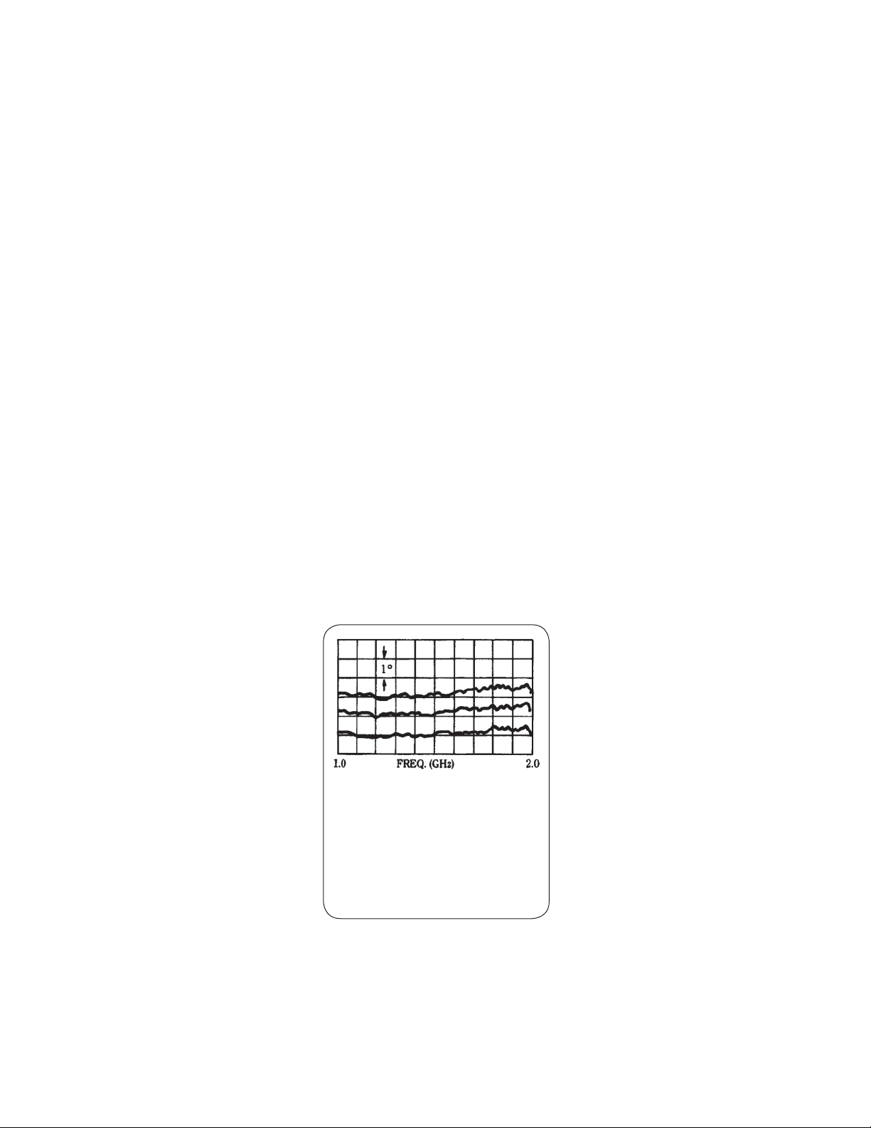
be kept to a minimum. The excellent
linearity of the Aglilent attenuators is
typified in the accompanying illustration of an actual network analyzer
measurement.
Center trace is phase response of 8491A
–6 dB attenuator from 1.0 to 2.0 GHz taken
with Agilent 8410 network analyzer. Top and
bottom traces are ±1° calibration. Linear
phase component has been compensated
for with a line stretcher. Response,
therefore, shows nonlinear phase deviation
of < ±½ ° over 1 to 2 GHz band.
Economy
Automated procedures have resulted
in economies of scale in production
and testing. The automated resistive
film deposition process permits highvolume manufacture with excellent
yield. Furthermore, characteristics are
consistently uniform; hand “touchup” is not required to meet specifications. Automatic testing means
exceptionallythorough, high-accuracy
measurements can be performed in
appreciably shorter time than could
be done manually.
The overall result is outstanding
attenuator performance at attractive
prices.
Calibration Data
Optional calibration data
Use of calibration data has always
been an effective means of reducing
measurement uncertainty at RF and
microwave frequencies. This data is
available for Agilent’s fixed attenuators as Option 849xx- UK6. Data
which is generated by an automatic
network analyzer provides a tabulated
list of attenuation and SWR’s at 26 to
67 frequencies (see table 2). Measurements to 60 dB are directly traceable
to NBS standards and feature very
low measurement uncertainties.
Option 849xx-UK6 data is available
when the attenuators are first purchased and recalibrations are available
through Agilent Customer Service
Centers around the world.
3
Page 4

Table 1. SWR data uncertainties
Connector type Frequency range (GHz)
Male Type -N
Female Type -N
Male SMA
Female SMA
Male APC-3.5
Female APC-3.5
Table 2. Coaxial attenuator calibration frequencies* (MHz)
100 4500 9000 13000 16750
500 5000 9500 13500 17000
1000 5500 10000 14000 17250
1500 6000 10500 14500 17500
2000 6500 11000 15000 17750
2500 7000 11500 15500 18000
3000 7500 12000 16000
3500 8000 12400 16250
4000 8500 12500 16500
*dc to 12.4 GHz models include 26 frequencies, dc to 18 GHz
models include 42 frequencies, dc to 26.5 GHz models include
67 frequencies (2 to 26.5 GHz).
dc to 12.4
12.4 to 18.0
dc to 8.0
8.0 to 12.4
12.4 to 18.0
dc to 8.0
8.0 to 12.4
12.4 to 18.0
dc to 8.0
8.0 to 12.4
12.4 to 18.0
dc to 8.0
8.0 to 12.4
12.4 to 18.0
dc to 10
10 to 18
18 to 26.5
(each 250 MHz
to 26.5 GHz
Measured SWR
1.0 to 1.35
±0.025
±0.031
±0.025
±0.031
±0.042
±0.031
±0.045
±0.077
±0.054
±0.077
±0.122
±0.025
±0.031
±0.045
±0.020
±0.025
±0.035
Measured SWR
1.35 to 1.86
±0.041
±0.050
±0.046
±0.063
±0.071
±0.054
±0.084
±0.137
±0.088
±0.132
±0.206
±0.041
±0.050
±0.067
±0.031
±0.037
±0.050
Table 3. Attenuation data uncertainties
Attenuation
(dB)
0.1 to 2.0 GHz 2 to 6 GHz 6 to 12.4 GHz 12.4 to 18.0 GHz 18.0 to 26.5 GHz
3 ±0.07 ±0.06 ±0.07 ±0.11 ±.15
6 ±0.07 ±0.07 ±0.07 ±0.11 ±.15
10 ±0.08 ±0.07 ±0.08 ±0.12 ±.15
20 ±0.09 ±0.08 ±0.09 ±0.13 ±.15
30 ±0.12 ±0.11 ±0.12 ±0.15 ±0.18
40 ±0.15 ±0.14 ±0.15 ±0.21 ±0.25
50 ±0.23 ±0.23 ±0.23 ±0.34 n/a
60 ±0.50* ±0.48* ±0.90* ±0.90* n/a
*The uncertainties noted represent 99.7% probability values.
8491, 8492 and 8493 Attenuation data uncertainty
(dB)
4
Page 5

Specifications:
Frequency Range:
Attenuation Accuracy:
Specifications describe the instruments warranted performance. Supplemental
characteristics (shown in italics) are intended to provide information useful
in applying the instrument by giving typical, but non-warranted, performance
parameters.
8491A and 8493A, dc to 12.4 GHz
8491B, 8493B, dc to 18 GHz
8493C, dc to 26.5 GHz
8491A/93A 8491B/93B 8493C
dc to 12.4 GHz dc to 12.4 / 12.4 to 18 GHz dc to 18 / 18 to 26.5 GHz
3 db ±0.3 dB ±0.3 dB ±0.5 dB / ±1.0 dB
6 dB ±0.3 dB ±0.3 dB / ±0.4 dB ±0.6 dB
10 dB ±0.5 dB ±0.6 dB ±0.3 dB / ±0.5 dB
20 dB ±0.5 dB ±0.6 dB / ±1.0 dB ±0.5 dB / ±0.6 dB
30 dB ±1.0 dB ±1.0 dB ±0.7 dB / ±1.0 dB
8491A only 8491B/92A only
40 dB ±1.5 dB ±1.5 dB ±1.0 dB / ±1.3 dB
50 dB ±1.5 dB ±1.5 dB N/A
60 dB ±2.0 dB ±2.0 dB N/A
SWR:
8491B/8493B
8491A/8493A 8493C
dc to 8
(GHz)
3 db 1.25 1.35 1.5 1.10 1.15 1.25
6 dB 1.2 1.3 1.5 1.10 1.15 1.27
10 dB 1.2 1.3 1.5 1.10 1.15 1.25
20 dB 1.2 1.3 1.5 1.10 1.15 1.25
30 dB 1.2 1.3 1.5 1.10 1.15 1.25
8491A/B only
40 dB 1.2 1.3 1.5 1.10 1.15 1.25
50 dB 1.2 1.3 1.5 N/A N/A N/A
60 dB 1.2 1.3 1.5 N/A N/A N/A
8 to 12.4
(GHz)
12.4 to 18
(GHz)
8491B only
dc to 8 8 to 12.4 12.4 to 26.5
5
Page 6

Environmental:
Connectors (50 Ω)
Dimensions
Weight
Millimeters 67 X 21 40 X 13 67 X 21 40 X 13
Inches 2
Net 110 g (4 oz) 30 g (1 oz) 110 g (4 oz) 30 g (1 oz) 8.5 g (0.3 oz) 9.4 g (0.33 oz)
Shipping 220 g (8 oz) 220 g (8 oz) 220 g (8 oz) 220 g (8 oz) 45 kg (1 lb)
Temperature: Operating 0°C to +55°C
Storage -55°C to +85°C
Humidity: Operating <95% relative at 40°C
Storage <95% relative at 40°C
Altitude: Operating <4,600 meters (15,000 feet)
Storage <15,300 meters (50,000 feet)
EMC: Radiated interference is within the requirements of MIL STD 461
method RE02, VDE 0871 EN55011 and FCC part 18
8491 A 8493A 8491B 8493B 8493C
2
Type-N
7/16 X 13/16 D1 9/16 X ½ D2 7/16 X 13/16 D1 9/16 X ½ D1 5/16 X 5/16 D1 7/16 X 5/16 D
SMA
1
Type-N
2
SMA
1
3,6,10,20 dB 30,40 dB
APC-3.5
33.8 X 8 36.8 X 8
Supplemental Characteristics:
Attenuator Sets
11581A/11582A/11583C
Ordering Information
Temperature stability:
0.000l dB/dB/°C (all except 8493C)
0.0002 dB/dB/°C (8493C)
Maximum input power: 2 W avg., 100 W peak
3
Power sensitivity: 0.001 dB/dB/W (all except 8943) 0.001 dB/W (8493C)
A calibrated set of four fixed coaxial attenuators (3, 6, 10, and 20 dB) is available.
Each set includes a calibration report certified traceable to the National Bureau
of Standards. The reports included with the 11581A, 11582A, and 11583C indicate
the accuracy of measurement and list the attenuation and reflection coefficient
at each port of the attenuator.
The set of four attenuators is furnished in a handsome walnut accessory case.
In addition to protecting the units when not in use, the case is also a convenient
storage place for the attenuators and the calibration reports. Calibration data as
described on page 4 is included with rack attenuator set.
To order, basic model number and option (specifies attenuation value) must be
specified. Option 849xx-UK6 calibration data can also be ordered with the basic
model number and attenuation value option. Please note, Option 849xx-UK6 is
not available with 1158½ A nor 11583C.
Attenuation options
1. As per USASI Committee C83.2 compatible
with OSM, ARM, WPM, BRM, NPM, etc.
2. Mate with MIL-C-71 or MIL-C-39012
connectors
3. At 20°C derated to l.3 W avg. at 55°C.
Option 003
Option 006
Option 010
Option 020
Option 030
Option 040
Option 050
Option 060
Note: x = A or B
Atten 8491A/B
options
8491A/B
options
8491A/B
options
3 dB 8491x-003 8493x-003 8493C-003
6 dB 8491x-006 8493x-006 8493C-006
10 dB 8491x-010 8493x-010 8493C-010
20 dB 8491x-020 8493x-020 8493C-020
30 dB 8491x-030 8493x-030 8493C-030
40 dB 8491x-040 8493C-040
50 dB 8491x-050
60 dB 8491x-060
6
Page 7

8491A/B
8493A/B
8493C
7
Page 8

www.agilent.com
s
www.agilent.com/find/mta
Agilent Email Updates
www.agilent.com/find/emailupdates
Get the latest information on the
products and applications you select.
www.axiestandard.org
AdvancedTCA® Extensions for
Instrumentation and Test (AXIe) is
an open standard that extends the
AdvancedTCA for general purpose
and semiconductor test. Agilent
is a founding member of the AXIe
consortium.
www.lxistandard.org
LAN eXtensions for Instruments puts
the power of Ethernet and the Web
inside your test systems. Agilent
is a founding member of the LXI
consortium.
www.pxisa.org
PCI eXtensions for Instrumentation
(PXI) modular instrumentation
delivers a rugged, PC-based highperformance measurement and
automation system.
Agilent Channel Partners
www. agilent.com/find/channelpartners
Get the best of both worlds: Agilent’s
measurement expertise and product
breadth, combined with channel
partner convenience.
Agilent Advantage Services is committed
to your success throughout your equipment’s lifetime. To keep you competitive,
we continually invest in tools and
processes that speed up calibration and
repair and reduce your cost of ownership.
You can also use Infoline Web Services
to manage equipment and services more
effectively. By sharing our measurement
and service expertise, we help you create
the products that change our world.
www.agilent.com/find/advantageservices
Agilent Electronic Measurement Group
DEKRA Certified
ISO 9001:2008
Quality Management SystemQuality Management Sy
www.agilent.com/quality
For more information on Agilent
Technologies’ products, applications or
services, please contact your local Agilent
office. The complete list is available at:
www.agilent.com/find/contactus
Americas
Canada (877) 894 4414
Brazil (11) 4197 3600
Mexico 01800 5064 800
United States (800) 829 4444
Asia Pacific
Australia 1 800 629 485
China 800 810 0189
Hong Kong 800 938 693
India 1 800 112 929
Japan 0120 (421) 345
Korea 080 769 0800
Malaysia 1 800 888 848
Singapore 1 800 375 8100
Taiwan 0800 047 866
Other AP Countries (65) 375 8100
Europe & Middle East
Belgium 32 (0) 2 404 93 40
Denmark 45 45 80 12 15
Finland 358 (0) 10 855 2100
France 0825 010 700*
*0.125 €/minute
Germany 49 (0) 7031 464 6333
Ireland 1890 924 204
Israel 972-3-9288-504/544
Italy 39 02 92 60 8484
Netherlands 31 (0) 20 547 2111
Spain 34 (91) 631 3300
Sweden 0200-88 22 55
United Kingdom 44 (0) 118 927 6201
For other unlisted countries:
www.agilent.com/find/contactus
Revised: January 6, 2012
Product specifications and descriptions
in this document subject to change
without notice.
© Agilent Technologies, Inc. 2012
Published in USA, September 7, 2012
5953-6475
 Loading...