

Page 1
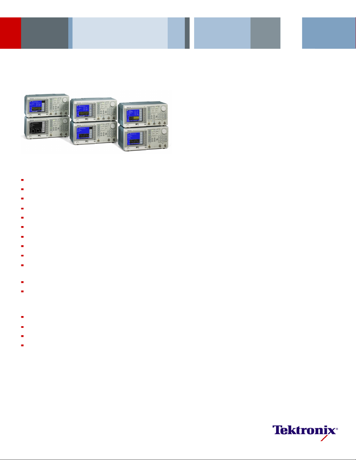
Arbitrary/Function Generators
AFG 3011 / 3021B / 3022B / 3101 / 3102 / 3251 / 3252 Datasheet
Product Description
Unmatched performance, versatility, intuitive operation, and affordability
make the AFG300 0 Series of Function, Arbitrary Waveform, and Pulse
Generators the most useful instruments in the industry.
Superior Performance and Versatility
Users can choose from 12 different standard waveforms. Arbitrary
waveforms can be generated up to 128 K in length at high sampling
rates. On pulse waveforms, leading and trailing edge time can be set
independently. External signals can be connected and added to the output
Features & Benefits
10 MHz, 25
14 bits, 250 MS/s, 1 GS/s, or 2 GS/s Arbitrary Waveforms
Amplitud
5.6 in. Display for Full Confidence in Settings and Waveform Shape
Multilan
Pulse Waveform with Variable Edge Times
AM, FM, PM
Sweep and Burst
Dual-ch
USB Connector on Front Panel for Waveform Storage on Memory
Device
USB, GPIB, and LAN
LabVIEW and LabWindows/IVI-C Drivers
MHz, 100 MHz, or 240 MHz Sine Waveforms
eupto20V
guage and Intuitive Operation Saves Setup Time
,FSK,PWM
annel Models Save Cost and Bench Space
into 50 Ω Loads
p-p
signal. Dual-channel models can generate two identical or completely
different s
±1 ppm drift per year.
Intuitive User Interface Shows More Information at a
Single Glance
A large scr
shape at a single glance. This gives full confidence in the signal settings
and lets you focus on the task at hand. Shortcut ke ys provide direct access
to frequently used functions and parameters. Others can be selected
conveniently through clearly structured menus. This reduces the time
needed for learning and relearning how to use the instrument. Look and feel
are identi
ArbExpress™ Software Included for Creating
Waveform
With this PC soft ware waveforms can be seamlessly imported from any
Tektroni
and waveform math.
ignals. All instruments feature a highly stable time base with only
een shows all relevant waveform parameters and graphical wave
cal to the world's most popular TDS3000 Oscilloscopes.
swithEase
x oscilloscope, or defined by standard functions, equation editor,
Applic
ations
Electronic Test and Design
Simulation
Sensor
Functional Test
ion and Training
Educat
Page 2

Datasheet
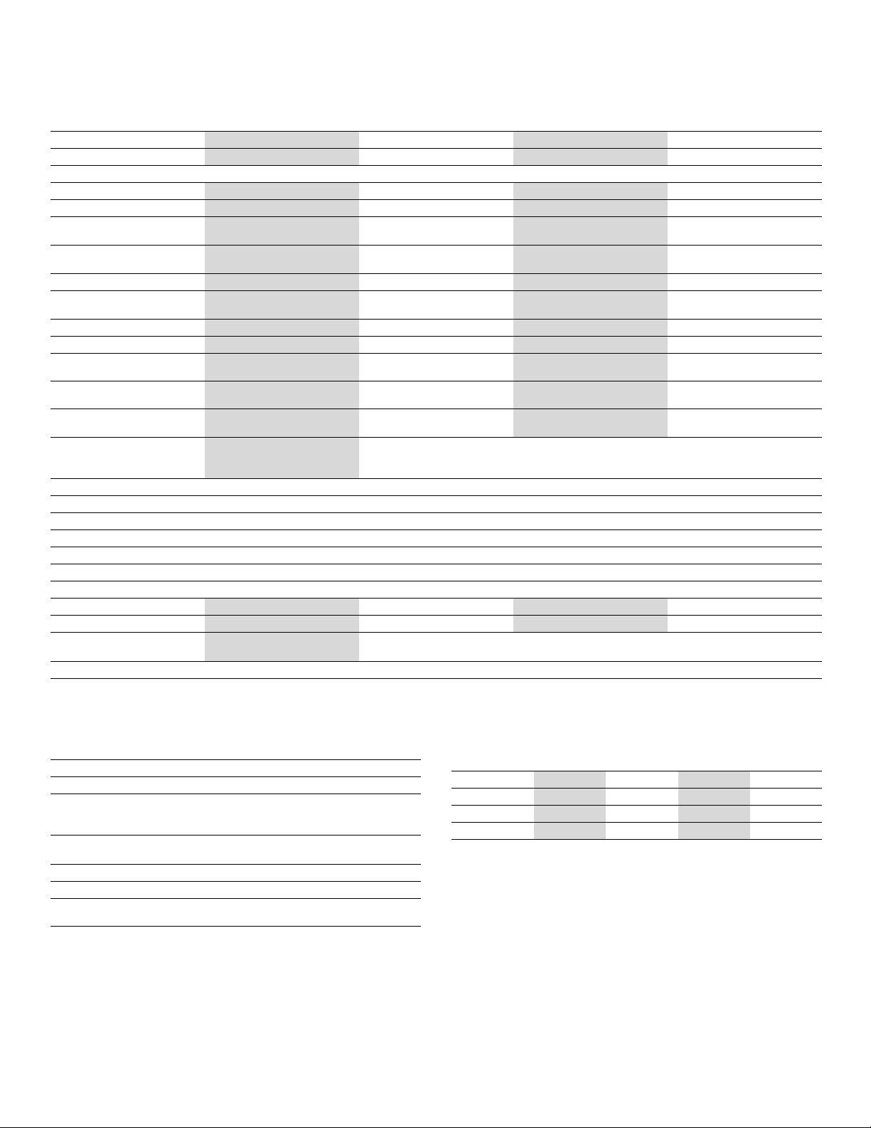
Characteristics
AFG3000 Serie
Characteristic AFG3011 AFG3021B
Channels
s Characteristics
AFG3022B
1
1/2 1/2 1/2
AFG3101
AFG3102
AFG3251
AFG3252
Waveforms Sine, Square, Pulse, Ramp, Triangle, Sin(x)/x, Exponential Rise and Decay, Gaussian, Lorentz, Haversine, DC, Noise
Sine Wave
Sine wave in Burst Mode
Effective maximum frequency
1 µHz to 10 MHz 1 µHz to 25 MHz 1 µHz to 100 MHz 1 µHz to 240 MHz
1µHzto5MHz 1µHzto12.5MHz 1µHzto50MHz 1µHzto120MHz
10MHz 25MHz 100MHz 240MHz
out
Amplitude Flatness (1 V
)
p-p
<5 MHz ±0.15 dB ±0.15 dB ±0.15 dB ±0.15 dB
5MHzto10MHz ±0.3 dB
5MHzto20MHz
20MHzto25MHz
25 MHz to 100 MHz
100MHzto200MHz
200MHzto240MHz
Harmonic Distortion (1 V
)
p-p
—
—
——
———
———
———
±0.3 dB ±0.3 dB ±0.3 dB
±0.5 dB ±0.3 dB ±0.3 dB
±0.5 dB ±0.5 dB
±1.0 dB
±2.0 dB
10 Hz to 20 kHz < -60 dBc < -70 dBc < -60 dBc < -60 dBc
20 kHz to 1 MHz < -55 dBc < -60 dBc < -60 dBc < -60 dBc
1 MHz to 5 MHz < -45 dBc < -50 dBc < -50 dBc < -50 dBc
5 MHz to 10 MHz < -45 dBc < -50 dBc < -37 dBc < -37 dBc
10MHzto25MHz
>25 MHz
THD
Spurious (1 V
p-p
)
—
——
< -40 dBc < -37 dBc < -37 dBc
<-37dBc <-30dBc
<0.2%(10Hz–20kHz,1V
p-p
)
10 Hz to 1 MHz < -60 dBc < -60 dBc < -60 dBc < -50 dBc
1MHzto10MHz <-50dBc
1MHzto25MHz
>25 MHz
Phase noise, typical
<-110dBc/Hzat10MHz,
10 kHz offset, 1 V
dual clock noise
Resi
Square Wave
Rise/Fall time
Jitter (RMS), typical
pWave
Ram
earity, typical
Lin
-63 d
1µHz
≤50 n
500 p
zto100kHz
1µH
≤0.2% of peak output ≤0.1% of peak output ≤0.15% of peak output ≤0.2% of peak output
—
——
p-p
Bm
to 5 MHz
s
s
———
< -50 dBc < -50 dBc < -47 dBc
< -50 dBc + 6 dBc/octave < -47 dBc + 6 dBc/octave
1µHz
1µH
Bm
-63 d
to 12.5 MHz
s
≤18 n
s
500 p
zto250kHz
<-110dBc/Hzat20MHz,10kHzoffset,1V
Bm
-57 d
to 50 MHz
1µHz
≤5ns
s
200 p
zto1MHz
1µH
p-p
-57 d
1µHz
≤2.5
zto2.4MHz
1µH
Bm
to 120 MHz
ns
s
100 p
Symmetry 0.0% to 100.0% 0.0% to 100.0%
se Wave
Pul
se width
Pul
solution
Re
lse duty
Pu
ge transition time
Ed
solution
Re
ad delay
Le
nge
Ra
zto5MHz
1mH
00 ns to 999.99 s
80.
ns to 625 s
50
ps or 4 digits
10
zto12.5MHz
1mH
00 ns to 999.99 s
30.
ps or 5 digits
10
zto50MHz
1mH
0 ns to 999.99 s
8.0
0.001% to 99.999% (Limitations of pulse width apply)
ns to 625 s
18
sto625s
5n
ps or 4 digits
10
(Continuous Mode): 0 ps to Period
zto120MHz
1mH
0 ns to 999.99 s
4.0
5nsto625s
2.
(Triggered/Gated Burst Mode): 0 ps to Period – [Pulse Width + 0.8 * (Leading Edge Time + Trailing Edge Time)]
Resolution 10 ps or 8 digits
Overshoot, typical <5%
Jitter (RMS), typical
500 ps 500 ps 200 ps 100 ps
2 www.tektronix.com
Page 3
Arbitrary/Function Generators — AFG 3011 / 3021B / 3022B / 3101 / 3102 / 3251 / 3252
Characteristic AFG3011 AFG3021B
AFG3022B
Other Waveforms
Noise Bandwidth (-3 dB)
1 µHz to 100 kHz 1 µHz to 250 kHz 1 µHz to 1 MHz 1 µHz to 2.4 MHz
10MHz 25MHz 100MHz 240MHz
Noise type
DC (into 50 Ω)
Arbitrary Waveforms
Arbitrary waveforms in Burst
-10Vto+10V -5Vto+5V -5Vto+5V -2.5Vto+2.5V
1 mHz to 5 MHz 1 mHz to 12.5 MHz 1 mHz to 50 MHz 1 mHz to 120 MHz
1mHzto2.5MHz 1mHzto6.25MHz 1mHzto25MHz 1mHzto60MHz
White Gaussian
AFG3101
AFG3102
AFG3251
AFG3252
Mode
Effective analog
8 MHz 34 MHz 100 MHz 225 MHz
bandwidth (-3 dB)
Nonvolatile memory
Memory: Sample rate 2 to 128 K: 250 MS/s 2 to 128 K: 250 MS/s >16 K to 128 K: 250 MS/s
4 waveforms 4 waveforms 4 waveforms 4 waveforms
>16 K to 128 K: 250 MS/s
2to16K:1GS/s
2to16K:2GS/s
Vertical resolution 14 bits 14 bits 14 bits 14 bits
Rise/Fall time
Jitter (RMS)
Amplitude, 50 Ω Load
tude, Open Circuit
Ampli
Accuracy
(1kHzsinewave,0Voffset,
Resolution 0.1 mV
Units
≤80 ns ≤20 ns ≤8ns ≤3ns
4ns 4ns
1nsat1GS/s
4nsat250MS/s
20 mV
to 20 V
40 mV
p-p
p-p
to 40 V
p-p
p-p
±(2% of setting +2 mV)
>20 mV
amplitude)
p-p
10 mV
20 mV
p-p
p-p
to 10 V
to 20 V
p-p
p-p
20 mV
40 mV
p-p
p-p
to 10 V
to 20 V
p-p
p-p
±(1% of setting +1 mV) (1 kHz sine wave, 0 V offset, >10 mV
,0.1mV
p-p
V
p-p,VRMS
, 1 mV, 0.1 dBm or 4 digits
RMS
,dBm(sinewaveonly)
≤200 MHz: 100 mV
>200 MHz: 100 mV
500 ps at 2 GS/s
4nsat250MS/s
≤200MHz: 50mV
>200 MHz: 50 mV
amplitude)
p-p
Output impedance 50 Ω
Load impedance setting
Selectable: 50 Ω,1Ω to 10.0 kΩ,HighZ(Adjustsdisplayedamplitudeaccordingtoselectedloadimpedance)
Isolation 42 Vpkmaximum to earth
Short-circuit protection Signal outputs are robust against permanent shorts against floating ground
External voltage protection
To protect signal outputs against external voltages use fuse adapter 013-0345-xx
DC offset range, 50 Ω load ±(10 Vpk– Amplitudepp/2) ±(5 Vpk–Amplitudepp/2) ±5 VpkDC ±2.5 VpkDC
DC offset range, open circuit ±(20 Vpk– Amplitudepp/2) ±(10 Vpk– Amplitudepp/2) ±10 VpkDC ±5 VpkDC
Accuracy
±(2% of |setting| + 10 mV + 1%
of amplitude (V
))
p-p
±(1% of |setting| + 5 mV + 0.5% of amplitude (V
))
p-p
Resolution 1 mV
p-p
p-p
p-p
p-p
to5V
to4V
to 10 V
to 8 V
p-p
p-p
p-p
p-p
Modulation
AM, FM, PM
Characteristic
Carrier Waveforms All, except Pulse, Noise, and DC
Source Internal/External
Internal Modulating
Waveform
Internal Modulating
Frequency
AM Modulation Depth
Min FM Peak Deviation
Max FM Peak
Deviation
Description
Sine, square, ramp, noise, ARB
(AM: maximum waveform length 4,096;
FM/PM: maximum waveform length 2,048)
2mHzto50.00kHz
0.0% to +120.0%
DC
See chart, below
Modulation: Max FM Peak Deviation
Characteristic AFG3011 AFG3021B
AFG3022B
Sine
Square
5 MHz 12.5 MHz 50 MHz 120 MHz
2.5 MHz 6.25 MHz 25 MHz 60 MHz
AFG3101
AFG3102
AFG3251
AFG3252
ARB 2.5 MHz 6.25 MHz 25 MHz 60 MHz
Others
50 kHz 125 kHz 500 kHz 1.2 MHz
PM Phase Deviation – 0.0° to +180.0°
www.tektronix.com 3
Page 4

Datasheet
Frequency Shift Keying
Characteristic
Description
Carrier Waveforms All, except Pulse, Noise, and DC
Source Internal/External
Internal Modulating
2 mHz to 1.000 MHz
Frequency
Number of Keys
2
Pulse Width Modulation
Characteristic
Carrier Waveform
Description
Pulse
Source Internal/External
Internal Modulating
Waveform
Internal Modulating
Sine, square, ramp, noise, ARB
(maximum waveform length 2,048)
2mHzto50.00kHz
Frequency
Deviation
0% to 50.0% of pulse period
Sweep
Characteristic
Description
Waveforms All, except Pulse, Noise, and DC
Type Linear, logarithmic
Sweep Time
Hold/Return Time
Max Total Sweep Time
1msto300s
0msto300s
300 s
Resolution 1 ms or 4 digits
Total Swe e p Tim e
≤0.4%
Accuracy, t ypical
Min Start/Stop
Frequency
Max Start/Stop
All except ARB: 1 µHz
ARB: 1 mHz
See chart, below
Frequency
Sweep: Max Start/Stop Frequency
Characteristic AFG3011 AFG3021B
MHz
Sine
Square
B
AR
Others
10
5M
5M
00 kHz
1
Hz
Hz
AFG3022B
MHz
25
.5 MHz
12
.5 MHz
12
50 kHz
2
AFG3101
AFG3102
Burst
escription
Characteristic
D
Waveforms All, except Noise and DC
ype
T
nternal Trigger Rate1μsto500.0s
I
Gate and Trigger
Triggered, gated (1 to 1,000,000 cycles or Infinite)
Internal, external, remote interface
Sources
10
50
50
1
0MHz
MHz
MHz
MHz
AFG3251
AFG3252
0MHz
24
0MHz
12
0MHz
12
.4 MHz
2
Auxiliary Inputs
Characteristic
Description
Modulation Inputs Channel 1, Channel 2
Input range
All except FSK: ±1 V
FSK: 3.3 V logic level
Impedance
Frequency range
10 kΩ
DC to 25 kHz (122 kS/s)
External Triggered/Gated Burst Input
Level TTL compatible
Impedance
10 kΩ
Pulse width 100 ns minimum
Slope P ositive/Negative, selectable
Trigger delay 0.0 ns to 85.000 s
Resolution 100 ps or 5 digits
Jitter (RMS), typical Burst: <500 ps (Trigger input to signal output)
10 MHz Reference Input
Impedance
Required Input
Voltage Swing
1kΩ, AC coupled
100 mV
p-p
to5V
p-p
Lock Range 10 MHz ±35 kHz
External Channel
AFG3101, AFG3102, A FG3251, AFG3252 only
1AddInput
Impedance
Input range
Bandwidth
50 Ω
-1Vto+1V(DC+peakAC)
DC to 10 MHz (-3 dB) at 1 V
p-p
Auxiliary Outputs
Characteristic
Description
Channel 1 Trigger Output
Level
Impedance
Positive TTL level pulse into 1 kΩ
50 Ω
Jitter (RMS), typical AFG3011/21B/22B: 500 ps
AFG3101/02: 200 ps
AFG3251/52: 100 ps
Max Frequency 4.9 MHz
(4.9 MHz t o 50 MHz: A fraction of the frequency is output;
>50 MHz: no signal is output)
10 MHz Reference Out AFG3101, AFG3102, AFG3251, AFG3252 only
Impedance
Amplitude
50 Ω, AC coupled
1.2 V
into 50 Ω load
p-p
4 www.tektronix.com
Page 5

Arbitrary/Function Generators — AFG 3011 / 3021B / 3022B / 3101 / 3102 / 3251 / 3252
Common Characteristics
Characteristic
Frequency Setting
Description
1 μHz or 12 digits
Resolution
Phase (except DC, Noise, Pulse)
Range
Resolution
Internal Noise Add
Level
Resolution
-180° to +180°
0.01° (sine), 0.1° (other waveforms)
When activated, output signal amplitude is reduced to 50%
0.0% to 50% of a mplitude (V
p-p
1%
Main Output 50 Ω
Effective
2 ms using remote control (sequencing not available)
Frequency
Switching Speed
Internal Frequency Reference
Stability All except ARB: ±1 ppm, 0 °C to 50 °C
ARB:±1ppm±1µHz,0°Cto50°C
Aging ±1 ppm per year
Remote
Programming
ration
Configu
typical
times,
Function
GPIB, LAN 10BASE-T / 100BASE-TX, USB 1.1
Compatible with SCPI-1999.0 and IEEE 488-2 standards
USB LAN GPIB
95 ms 103 ms 84 ms
change
Frequency
2ms19ms2ms
change
Amplitude
60 ms 67 ms 52 ms
change
Select user
88 ms 120 ms 100 ms
ARB
Data download
20 ms 84 ms 42 ms
time for
4000 point
waveform data,
typical
Power Source
Power
100 to 240 V, 47 to 63 Hz, or 115 V, 360 to 440 Hz
Less than 120 W
Consumption
Warm-up Time,
20 minutes
typical
Power-on Self
<16 s
Calibration, typical
Acoustic Noise,
<50 dBA
typical
Display
AFG3021B: 5.6 in. Monochrome LCD
All others: 5.6 in. Color LCD
User Interface and
Help Language
English, French, German, Japanese, Korean, Simplified and
Traditional Chinese, Russian (user selectable)
) setting
Physical Characteristics
stic
guration
mm
in.
5.9 12.9
Description
-30°Cto+70°C
> +40 °C to 50 °C: ≤60%
Up to 10,000 ft./3,000 m
EN 61326:1997 Class A
EN 61000-3-2:2000, and EN 61000-3-3:1995
IEC 61000-4-2:1999, -4-3:2002, -4-4:2004, -4-5:2005,
-4-6:2003, -4-11:2004
UL 61010-1:2004
CAN/CSA C22.2 No. 61010-1:2004
IEC 61010-1:2001
Benchtop Confi
Dimensions
Height 156.3 6.2
Width 329.6 13.0
Depth 168.0 6.6
Weight kg lb.
Net 4.5 9.9
Shipping
Environmental and Safety Characteristics
Characteri
Temperature
Operating 0 °C to +50 °C
Nonoperating
Humidity
Operating ≤ +40 °C: ≤80%
Altitude
EMC Compliance
European Union
Australia EN 61326:1997
Safety
www.tektronix.com 5
Page 6

Datasheet
BNC Fuse Ada
pter and 0.125 A Fuse
Ordering Information
AFG3011, AFG3021B, AFG3022B, AFG3101, AFG3102,
AFG3251, AFG3252
Arbitrary/Function Generator
:
Includes
programm
ArbExpre
power pl
Interna
Option
Opt. A0
Opt. A1 Universal EURO power
Opt. A2
Opt. A3
Opt. A5 Switzerland power
Opt. A6
Opt. A10 China power
Opt. A11
Opt. A99 No power cord or AC adapter
Note: Includes front-panel overlay.
Quick-start user manual, power cord, USB cable, CD-ROM with
er manual, service manual, LabView and IVI drivers, CD-ROM with
ss™ software, and NIST-traceable calibration certificate. Please specify
ug when ordering.
tional Power Plugs
Description
North America power
United Kingdom power
Australia power
Japan power
India power
Service
Option
Opt. C3 Calibration Service 3 Years
Opt. C5 Calibration Service 5 Years
Opt. CA1 Single calibration event or coverage for the designated
Opt. D1 Calibration Data Report
Opt. D3 Calibration Data Report 3 Years (with Opt. C3)
Opt. D5 Calibration Data Report 5 Years (with Opt. C5)
Opt. R5 Repair Service 5 Years
Opt. SILV200 Standard Warranty Extended to 5 Years (AFG3011,
Opt. SILV400 Standard Warranty Extended to 5 Years (AFG3251 and
Description
calibration interval, whichever comes first
AFG3021B, AFG3022B, AFG3101, and AFG3102)
AFG3252)
Warranty
Three-year warranty on parts and labor.
Recommended Accessories
Accessory Description
Rackmount Kit RM3100
apter, BNC-P
Fuse ad
R
to BNCFuse set, 3 pcs,
0.125 A.
BNC cable shielded,
3 ft.
BNC cable shielded,
9 ft.
GPIB cable, double
shielded
013-0345-xx
159-0454-xx
012-0482-xx
012-1256-xx
012-0991-xx
Tektronix is registered to ISO 9001 and ISO 14001 by SRI Quality System Registrar.
Product(s) complies with IEEE Standard 488.1-1987, RS-232-C, and with Tektronix
Standard Codes and Formats.
Manual Options
Option
Opt. L0 English (071-1631-xx)
Opt. L1 French (071-1632-xx)
Opt. L2 Italian (071-1669-xx)
Opt. L3 German (071-1633-xx)
Opt. L4 Spanish (071-1670-xx)
Opt. L5 Japanese (071-1634-xx)
Opt. L7 Simple Chinese (071-1635-xx)
Opt. L8 Traditional Chinese (071-1636-xx)
Opt. L9 Korean (071-1637-xx)
Opt. L10 Russian (071-1638-xx)
Opt. L99
Description
No manual
6 www.tektronix.com
Page 7

Arbitrary/Function Generators — AFG 3011 / 3021B / 3022B / 3101 / 3102 / 3251 / 3252
www.tektronix.com 7
Page 8

Datasheet
Contact Tektronix:
ASEAN / Australa
Balkans, Israel, South Africa and other ISE Countries +41 52 675 3777
Central East Eu
Mexico, Central/South America & Caribbean 52 (55) 56 04 50 90
Middle East,
* European toll-free number. If not accessible, call: +41 52 675 3777
rope and the Baltics +41526753777
Central Europe & Greece +41 52 675 3777
Asia, and North Africa +41 52 675 3777
The Netherlands 00800 2255 4835*
People’s Rep
Republic of
United K ingdom & Ireland 00800 2255 4835*
sia (65) 6356 3900
Austria 00800 2255 4835*
Belgium 00800 22
Brazil +55(11)37597627
Canada 1 800 833 920 0
Denmark +4580881401
Finland +41526
France 00800 2255 4835*
Germany 00800 2255 4835*
Hong Kong 400 8
India 000 800 650 1835
Italy 00800 2255 4835*
Japan 81 (3) 67
Luxembourg +41526753777
ublic of China 400 820 5835
Poland +41 52 675 3777
Korea 001 800 8255 2835
Russia & CIS +7 (495) 7484900
South Africa +41526753777
Spain 00800
Sweden 00800 2255 4835*
Switzerland 00800 2255 4835*
Tai wa n 886 (
55 4835*
75 3777
20 5835
14 3010
Norway 800 16098
Portugal 80 08 12370
2255 4835*
2) 2722 9622
USA 1 800 833 9 200
Updated 10 February 2011
www.tektronix.com
For Further Information. Tektronix maintains a comprehensive, constantly expanding
collection of application notes, technical briefs and other resources to help engineers working
on the cutting edge of technology. Please visit www.tektronix.com
t © Tektronix, Inc. All rights reserved. Tektronix products are covered by U.S. and foreign patents,
Copyrigh
d pending. Information in this publication supersedes that in all previously published material.
issued an
tion and price change privileges reserved. TEKTRONIX and TEK are registered trademarks of
Specifica
x, Inc. All other trade names referenced are the service marks, trademarks, or registered trademarks
Tek t ro n i
espective companies.
of their r
27 Jul 2012 76W-18656-5
 Loading...