

Page 1
AES 5501
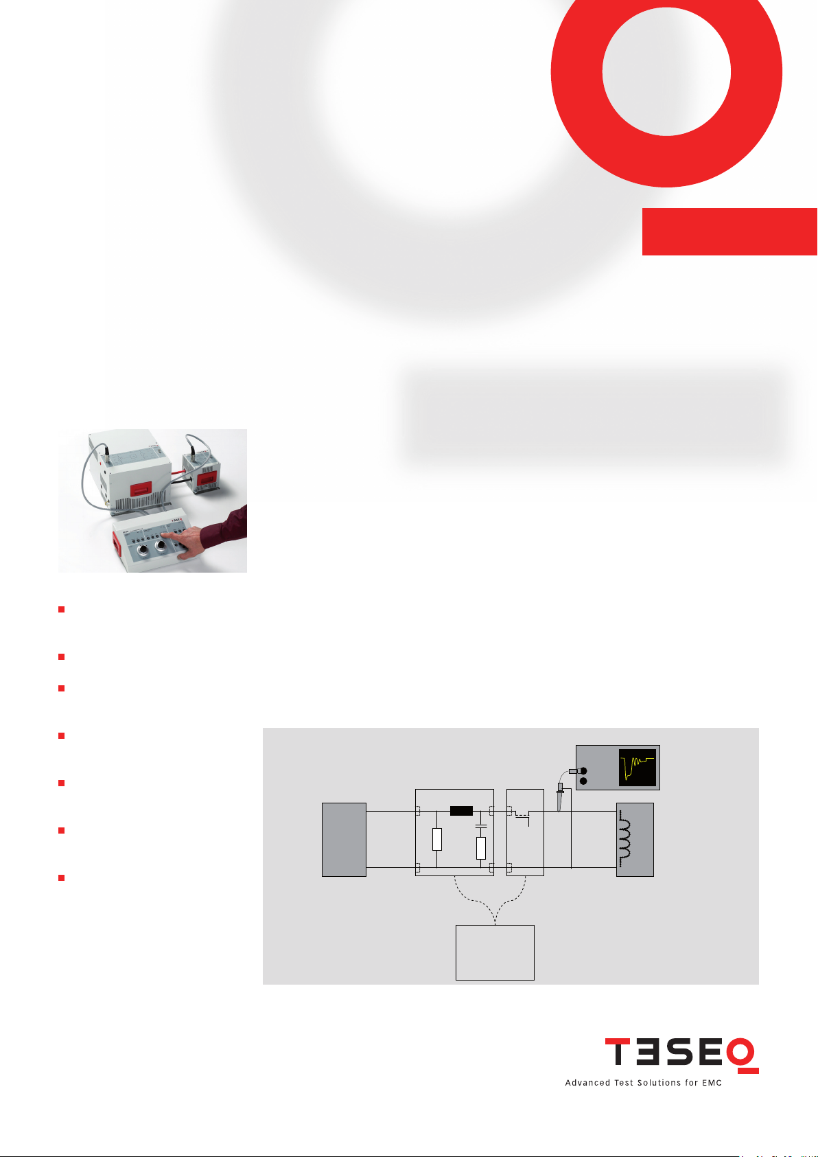
Oscilloscope
EUT
Battery
Source
ES 5501AN 5501
SC 5501
AUTOMOTIVE EMISSIONS SYSTEM FOR ISO 7637-2
The AES 5501 is a system of electronic and mechanical switches, an artifi cial network, and a unique
control station designed for emissions testing to ISO 7637-2. Having gone through meticulous development and intensive beta testing, the AES 5501 contains unique features and uncompromising quality
and conformity found nowhere else. Consisting of a four-part solution, the user has complete control
over where, when and how the switches can be placed and controlled, including the necessary drive
voltages for the relays.
The 100 A connectors are carefully placed and countersunk to allow precise cabling between the
switches, the artifi cial network and test bench and allows for the electronic or mechanic switches to be
placed at any point before or after the artifi cial network. Multiple switches may also be utilized at the
same time as required. This careful attention to detail for switch placement and cable length means
The only complete, compliant
solution for ISO 7637-2 emissions
testing
Clean, reliable 100 A operation
with very low voltage drop
Industry standard relay footprint
for a wide selection of relays
(one 100 A relay included)
Separate control station with au-
tomatic, manual or external triggering of the switching behavior
Smaller switch enclosure for
easier compliance to various
cable-length requirements
Totally redesigned AN with
improved, fully compliant impedance curve
Convenient measurement ports
that numerous manufacturer standards can also be met. The AES 5501 features a rugged construction
with unpainted underside for good earth contact, precise switching control and numerous monitoring
locations. A counter for the relay and LED indicators for both electronic and mechanical switches are provided. The AES 5501 has temperature controlled fans for quiet operation and a thermal shutdown feature.
Block diagram
Page 2
AES 5501
AUTOMOTIVE EMISSIONS SYSTEM FOR ISO 7637-2
Electronic switch - typical switching curve with test load
Teseq AG
Nordstrasse 11F 4542 Luterbach Sw itzerl and
T + 41 32 681 40 40 F + 41 32 681 4 0 48
sales@tese q.com www.teseq.com
© Februa ry 2011 Teseq®
Specifications subject to change without notice.
®
Tes eq
is an ISO-registered company. Its products
are designed and manufactured under the strict
quality and environmental requirement s of the ISO
9001. This documen t h as been carefully checked.
However, Teseq
errors or inaccuracies.
691-268B Februar y 2011
®
does not assume any liability for
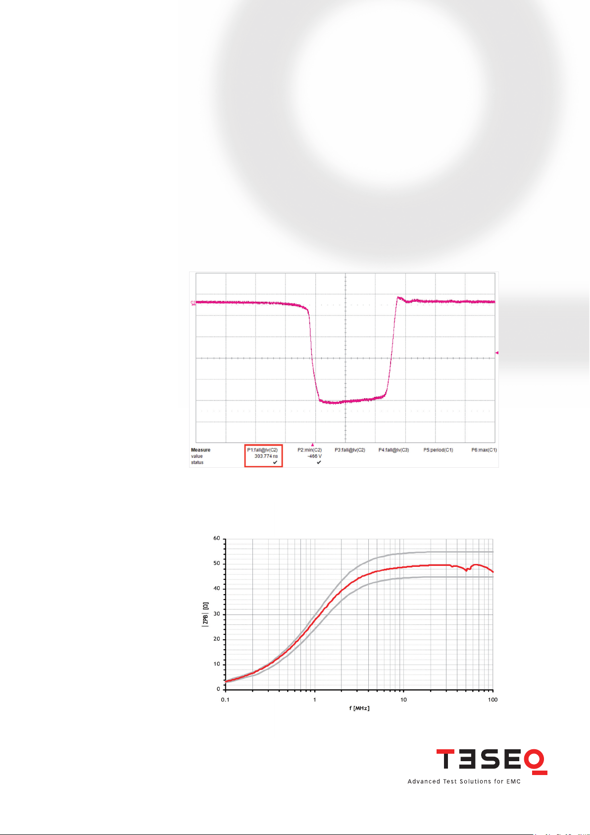
Typical impedance curve of AN 5501
Page 3

AES 5501
AUTOMOTIVE EMISSIONS SYSTEM FOR ISO 7637-2
Technical specifications
Teseq AG
Nordstrasse 11F 4542 Luterbach Sw itzerl and
T + 41 32 681 40 40 F + 41 32 681 4 0 48
sales@tese q.com www.teseq.com
© Februa ry 2011 Teseq®
Specifications subject to change without notice.
®
Tes eq
is an ISO-registered company. Its products
are designed and manufactured under the strict
quality and environmental requirement s of the ISO
9001. This documen t h as been carefully checked.
However, Teseq
errors or inaccuracies.
®
does not assume any liability for
Complete system
1)
Battery current 100 A
Inrush current
2)
300 A for 200 ms
Battery voltage 0 to 60 VDC
Shunt resistor (R
) 10, 20, 40, 120 Ω, Ext.
S
Trigger modes External, internal, manual
Battery off time (t
Battery on time (t
) 10 ms – 10 s ±(10% + 10 ms)
off
) 0.5 ms – 10.5 s ±(10% + 10 ms)
on
Mains input voltage 85 – 264 VAC, 47 – 63 Hz
Available relay voltage 12, 24, 36 V (for 42 V applications)
Electronic switch
Switching time Δt
300 ns ±20%
S
3)
Voltage drop <1 V @ 25 A
Typical 2.1 V @ 100 A
Transient voltage protection 440 V
Mechanical switch
Type Automotive relay
Contacts High purity AgNi with no suppression across contacts
Voltage rating > 400 V
Artifi cial network
Inductance 5 µH
Capacitance 0.1 µF
Resistance 50 Ω
Impedance As per ISO 7637-2 (see above impedance curve)
Connectors 100 A MC type, countersunk, 50 mm above ground plane
Housing Stainless steel, unpainted underside, screw terminal and
earth connections
Indicators Counter on relay, LED indicator on controller for mechanical
and electronic switches
Measurements ports MS 5501, ES 5501 - directly connected to output
AN 5501 – 5.6 k output impedance (to output connector –
necessary for improved RF performance)
Physical dimensions (L x W x H) ES 5501 125 x 125 x 125 mm
MS 5501 125 x 125 x 125 mm
AN 5501 340 x 270 x 205 mm
All tolerances ± 10% unless otherwise noted.
691-268B Februar y 2011
Page 4

AES 5501
125 mm
50 mm
AUTOMOTIVE EMISSIONS SYSTEM FOR ISO 7637-2
1) Active, temperature dependant cooling. The ES 5501 is depending on duty cycle, approximately
3 minutes at 100 A with 100% duty cycle before the switch will be deactivated for cooling.
2) With supplied relay or electronic switch
3) With test load defi ned in ISO 7627-2. Purely resistive loads display typically in the range of a few
microseconds.
Accessories
Included: 4 x 60 mm cable, MC connector
Included: 2 x 100 mm cable, MC connector
Included: 4 x 0 mm pin, used when the housings will be pushed together (for zero millimeter distance)
Included: INA 5031 – 100:1 high voltage probe compliant to ISO 7637-2
Optional: INA 163 – Set of ten MC to banana adapters (only available in red)
Optional: INA 5500-TL – Reference load (R = 0.6 Ω, L = 50 µH)
Optional: INA 5500-CK – Calibration kit for impedance curve verifi cation (used for connection to
network analyzer)
Optional: MS 5501 – Additional unit for additional prepared relays
Optional: Various inserts for MC 5501 for industry standard relay footprints
Teseq AG
Nordstrasse 11F 4542 Luterbach Sw itzerl and
T + 41 32 681 40 40 F + 41 32 681 4 0 48
sales@tese q.com www.teseq.com
© Februa ry 2011 Teseq®
Specifications subject to change without notice.
®
Tes eq
is an ISO-registered company. Its products
are designed and manufactured under the strict
quality and environmental requirement s of the ISO
9001. This documen t h as been carefully checked.
However, Teseq
errors or inaccuracies.
691-268B Februar y 2011
®
does not assume any liability for
Switch housings are compact, optimized for comformity to strict layout requirements and
offer ample earth contacts.
 Loading...