

Page 1
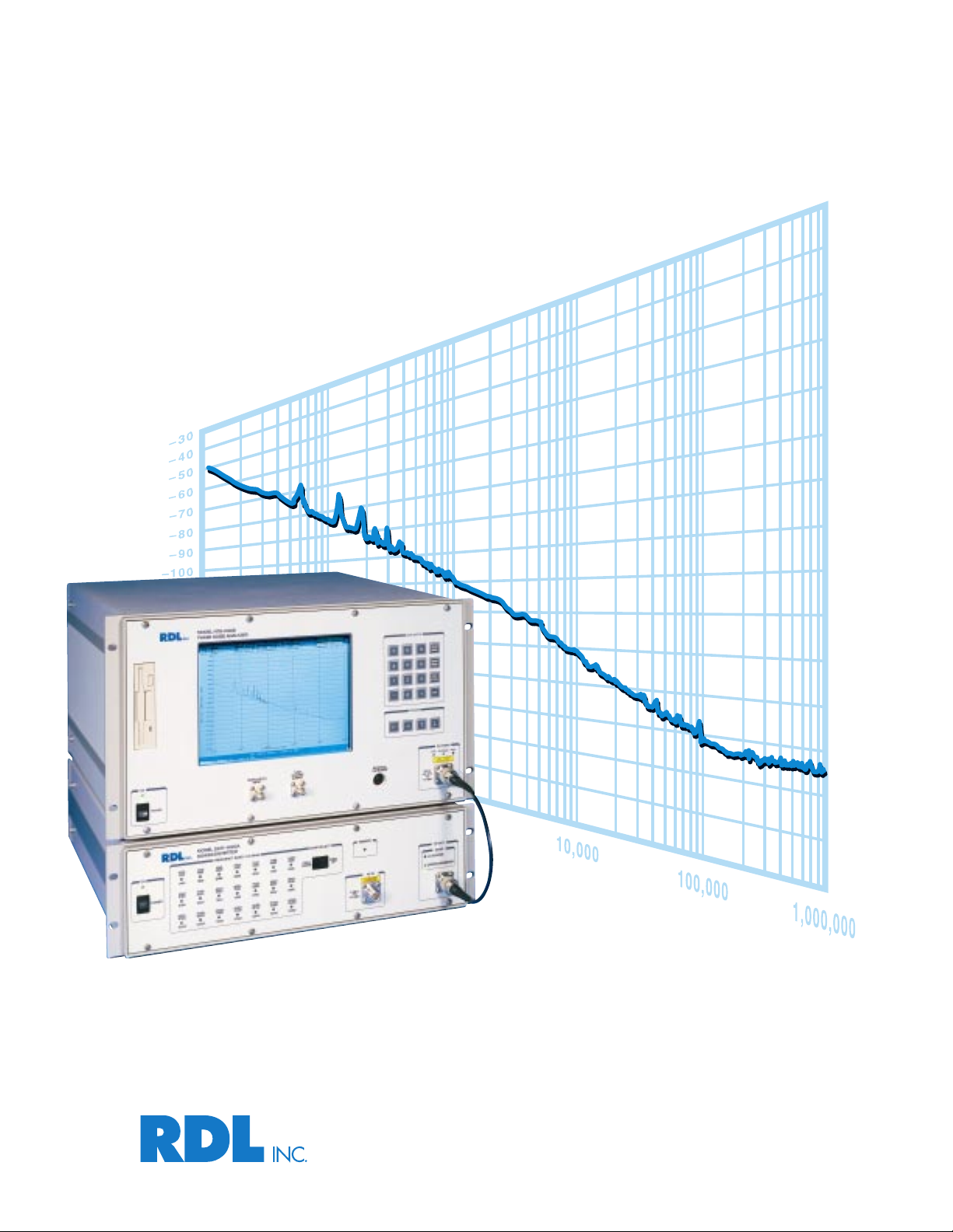
Phase Noise
Analyzer
System
With New Low Noise Downconverter
Frequency Generation and Noise Measurement for Critical Applications
7th Ave. & Freedley St. •Conshohocken, PA 19428 •610-825-3750 •Fax 610-825-3530
Automated Phase Noise
Measurements . . . In Seconds
2005K
Page 2

NTS -1000B
Phase Noise
Analyzer
Proven Measurement Technique
The NTS-1000B Phase Noise Analyzer uses
the proven “delay-line discriminator” measurement technique to accurately measure
Phase Noise at offsets between 10 Hz and 1
MHz. The NTS-1000B performs a precise calibration at the measured frequency before
every measurement to insure measurement
accuracy.
Self Contained
The RDL Model NTS-1000B Phase Noise
Analyzer is a unique instrument that, for
the first time, allows phase noise testing of
every part. An FFT digital signal processor
and vibration-hardened delay line are contained inside the unit. No external signal
generator or outside computer are
required.
Easy To Use
Measurements are made by simply pushing the “start measurement” button or
sending an IEEE bus command. No spe-
cial training or skills are required to
operate the RDL Model NTS-1000B.
Phase locking is not required. Automatic
“pass/fail” analysis of phase noise levels
and spurious levels is provided. These
levels are user defined and the results
can be reported over the IEEE-488 bus.
Fast Measurements
The “measurement range” and “number of
FFT averages” are selectable by the user to
optimize measurement time. The NTS1000B only measures in the selected range
to minimize the measurement time. In
production applications, where extreme-
ly fast measurements are needed, the
NTS-1000B can measure and report
the results in less than 2 seconds.
Typical measurement time for a
full range measurement, 10 Hz to
1 MHz, with 100 FFT averages,
is only 30 seconds, including an
automatic calibration.
Page 3

NTS–1000B and DCR–14000A-03
The latest microwave synthesizers and the YIG
and DRO oscillators used in these sub-systems
now have phase noise levels that are lower
than even the most sophisticated military
requirements of the past. The new "Low Noise
Option" for the DCR-14000A, the –03 Option,
lowers the noise floor levels of the RDL Phase
Noise Analyzer System to easily measure to
these new levels. The fact that "phase locking"
is not required and the "10 second measurement speed" makes this measurement routine.
Getting near instantaneous test results allows
in-process adjustment to obtain optimum
phase noise performance. These devices can
now be subject to SPC and variations in the
manufacturing process can be monitored, on
line, and corrected before shipments are
impacted. The table shows the phase noise
performance of the DCR-14000A-03.
Typical Noise Floor dBc/Hz
Offset 10 kHz 100 kHz 1 MHz
Band
1.00 to 1.38 -147 -159 -160
1.38 to 1.86 -145 -158 -159
1.86 to 2.50 -144 -157 -158
2.50 to 3.14 -141 -155 -156
3.14 to 3.78 -140 -154 -155
3.78 to 4.42 -138 -151 -152
4.42 to 5.06 -135 -150 -151
5.06 to 5.70 -135 -150 -151
5.70 to 6.34 -135 -149 -150
6.34 to 6.98 -133 -149 -150
6.98 to 7.62 -133 -147 -148
7.62 to 8.26 -133 -146 -147
8.26 to 8.90 -131 -146 -147
8.90 to 9.54 -131 -144 -145
9.54 to 10.18 -131 -144 -145
10.18 to 10.82 -129 -143 -144
10.82 to 11.46 -129 -143 -144
11.46 to 12.10 -129 -140 -141
12.10 to 12.74 -128 -140 -141
12.74 to 13.38 -128 -140 -141
13.38 to 14.70 -128 -140 -141
14.70 to 18.50 Option-01 -128 -140 -141
18.50 to 24.94 Option-01 -127 -140 -141
Typical Noise Floor
NTS-1000B and DCR-14000A-03
RF Input Frequency 10,200.5 MHz
Offset Frequency (Hz)
Noise (dBc/Hz) SSB
Page 4
Input Frequency
2083.9 MHz
NTS–1000B and DCR–2500A
The new PCS applications have placed high
demands on the designer and manufacturer. The
constant push to better utilize the available spectrum has made phase noise one of the most important parameters. Phase synchronous modulation
has placed further demands on this critical parameter. Since every dB is critical and costly, accurate
measurement is now a requirement, not a luxury.
The RDL Phase Noise Analyzer System that consists
of the NTS-1000B and DCR-2500A provides unique
measurement capabilities that are not available
from other suppliers. The ability of the NTS-1000B
to measure unlocked sources, in seconds, combined
with the very low phase noise in the DCR-2500A
Downconverter extends the measurement of phase
noise from the lab into the factory.
In the past phase noise measurements have been
confined to the laboratory due to the complexity of
the measurement techniques and the time consum-
ing tools that have been available. The RDL
System makes this a push-button measurement
that can be made by non-technical personnel or
under IEEE bus control. The built-in printer port
and easy data manipulation makes documenting
phase noise measurements a snap, and for the
first time, makes statistical process control of this
critical parameter feasible.
The low noise floor of the RDL System opens up
the possibility of really measuring what is going
on in a synthesizer’s design. Now the noise of the
PLL can be separated from the noise of the VCO
and real design improvements can be analyzed
and implemented.
Now you don’t have to specify an over-designed
VCO and pay for performance you can not confirm
or use. The RDL System is so simple and fast that,
for the first time, you can consider testing every
product in production.
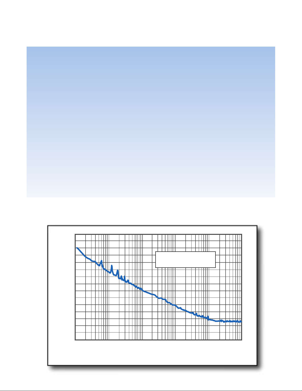
Typical Noise Floor NTS-1000B and DCR-2500A
(Corrected for Source Noise)
–30
–40
–50
–60
–70
–80
–90
–100
–110
–120
–130
Noise (dBc/Hz) SSB
–140
–150
–160
–170
–180
10 100 1,000 10,000
Offset Frequency (Hz)
100,000 1,000,000
Page 5
NTS -1000B SPECIFICATIONS
Frequency Range: 50 to 1100 MHz
Frequency counter resolution: 100 kHz
RF Input Level: –20 to +10 dBm
Spectral Analysis: FFT; Hanning
Measurement Accuracy: ±2 dB
Calibration: Automatic, before every measurement.
Analysis Range: 10 Hz to 1 MHz in 3 bands
Measurement Speed, includes calibration:
10 Averages:
~
10 sec. (full analysis range)
100 Averages:
~
30 sec. (full analysis range)
Under remote control: <1.2 sec. (1 kHz to 100 kHz
analysis range)
Input Frequency Stability: ±20 kHz during measurement
(measurement time is a function of which analysis band(s) are selected
and number of FFT averages selected)
Averaging: Selectable 1, 5, 10, 15, 20,
25, 50, 100 averages
Pass/Fail Analysis: User defined limits for noise analysis.
Spurious Identification User defined limits and analysis criteria.
& Analysis:
Integrated Noise Analysis: Computes integrated noise (dBc SSB)
over user defined range(s).
Front & Rear Panel Input: Type N
Printer Port: Centronix parallel port (LPT1)
VCO Tune Voltage:
Range: ±30 Volts
Resolution: 0.1 Volt
Noise:
~
13 nV/
Ö Hz 5 kHz
Modulation Input: Used to apply modulation signal to
the VCO tune voltage.
Typical Noise Floor dBc/Hz SSB Input > +6 dBm
Offset 10Hz 100 Hz 1 kHz 10 kHz 100 kHz 1 MHz
Input Frequency
80 MHz –49 –81 –107 –130 –151 –160
160 MHz –49 –81 –107 –130 –150 –159
320 MHz –48 –80 –107 –130 –150 –158
640 MHz –48 –80 –107 –130 –150 –158
960 MHz –45 –78 –104 –130 –150 –158
General Data:
Remote Control: IEEE-488.2
AC Power: 99-121 and 198-242 Volts, 47-63 Hz
EMC: Meets the requirements of CE
and FCC Part 15.
Size: 22 x 17.5 x 10.5 inch (D x W x H)
Weight: 85lbs. net, 120lbs. shipping
1503800-300
Specifications subject to change without notice.
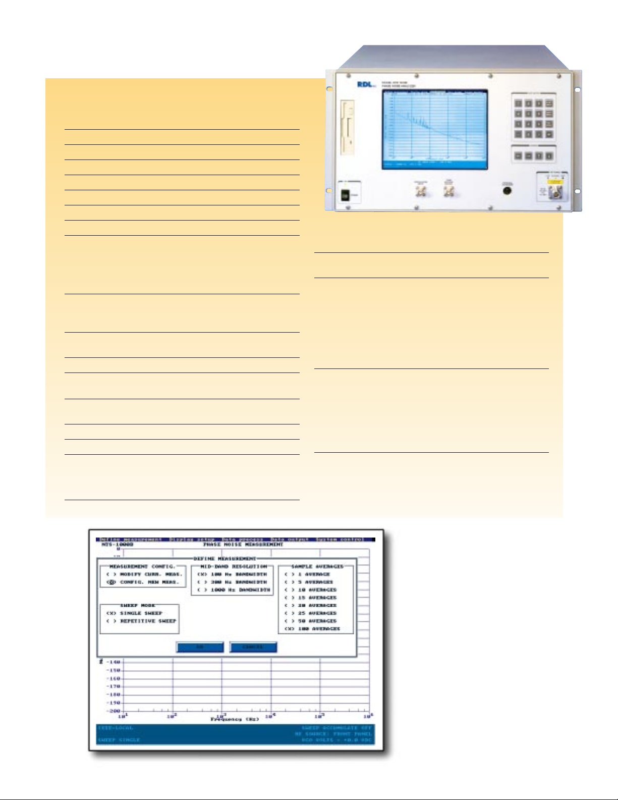
Define Measurement
The user can set the “Number
of Averages” and “Mid-band
resolution” bandwidth to
optimize measurement time.
“Repetitive Mode” may be
selected to further speed the
measurement.
Page 6

Data Output
Measurement results can be
saved to the integral 3.5” disk
drive or output to the integral
printer port(s). The results of the
“Integrated Noise” and “Spur
List” can also be output. Virtually
every measurement result and
control is available over the integral IEEE-488 Bus.
Display Setup
Menus define the measurement
range, “Display Limits,” and
“Measurement Type.” The “Graph
Title” can be input, using a standard
PC keyboard, so that printer plots
contain identifying nomenclature.
The “Accumulate Data” mode can
be selected so that multiple measurements can be displayed and
compared. The “Store Sweep”
modes provide means to “screen
save” an existing measurement or a
“disk stored” measurement can be
transferred to the display screen.
Data Processing
Definition of the frequency
limits for calculating
“Integrated Noise” is user
defined along with the range
and thresholds for”Spur
Identification” and “Noise
Spec Lines”. The starting
frequency of the “Moveable
Marker” is also available.
Page 7
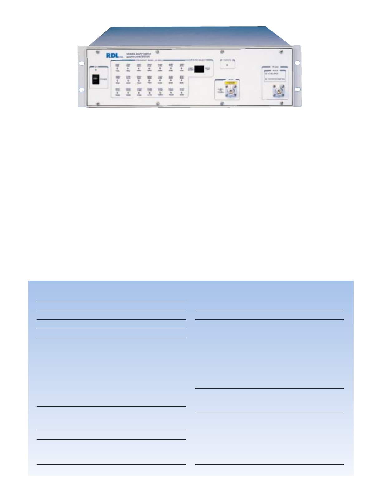
The RDL Model DCR-14000A Downconverter utilizes
technology that RDL developed for military radar systems. The LOs are based on seven very low noise
sources that are based on an 80 MHz crystal oscillator.
These are mixed and matched to create 21 separate
bands, each with very low phase noise. The output conversion gain is nominally 3 dB and the input required
is only 0 dBm. You won’t need to find a low-noise
microwave amplifier to make your signal big enough
to measure. The output is band limited to 60-700 MHz.
The basic unit covers the frequency range of 1 to 14.7
GHz. There is continuous frequency coverage, no
holes around each LO, and the phase noise levels are
state-of-the-art.
The frequency range of the DCR-14000A can be extended to 25 GHz with Option 01. The 10.24 GHz LO that is
available full time inside the DCR-1400A is made available on the rear panel for mixing from higher frequencies. The phase noise performance of the DCR-14000A
at these higher frequencies is virtually the same as at
the lower bands because this LO’s noise is correlated
with the noise of the other LOs. The 10.24 GHz signal
is +10 dBm to accomodate a wide range of mixers.
The DCR-14000A can also be configured as a source.
Option 02 is available where the individual LOs of the
DCR-14000A can be output. Applications such as measuring the phase noise of a block downconverter is easy.
The DCR-14000A’s LOs can be the input and the output
of the converter, usually within the frequency range of
the NTS-1000B, can be measured directly, without locking, and you will know that the noise you are measuring
is the noise of the DUT, not the noise of the source.
DCR-14000A SPECIFICATIONS
Frequency Range:
1 to 14.7 GHz, 21 bands
Output Frequency Range:
60 to 700 MHz
Input Level Range –10 to 0 dBm
Output Conversion Gain: 3 db;
± 3 dB
Typical Noise Floor dBc/Hz SSB @ 0 dBm input level
Frequency Range Offset 100 Hz 1 kHz 10 kHz 100 kHz 1 MHz
GHz Bands
1.00 – 2.50 3 –106 –136 –143 –144 –145
2.50 – 4.42 3 –101 –131 –138 –140 –141
4.42 – 6.34 3 –98 –128 –135 –137 –138
6.34 – 8.26 3 –96 –126 –133 –135 –136
8.26 – 10.18 3 –94 –124 –131 –133 –134
10.18 – 12.10 3 –92 –122 –129 –131 –132
12.10 – 14.78 3 –91 –121 –128 –130 –131
Option 01 Frequency Extension:
10.24 GHz LO for external mixing from 25 GHz
Output: Rear Panel; +9 dBm ± 1 dB; Type N connector.
Typical Noise Floor dBc/Hz SSB
Offset 100Hz 1 kHz 10 kHz 100 kHz 1 MHz
10.24 GHz –93 –121 –130 –133 –134
Option 02 Source Option:
There are 21 selectable output frequencies from 1.44 GHz to 14.08 GHz.
Output: ; +9 dBm ±3 dB; Type N connector
Typical Noise Floor dBc/Hz SSB
Offset 100Hz 1kHz 10 kHz 100 kHz 1 MHz
Output Frequencies
1.44, 1.92 & 2.56 GHz –106 –136 –143 –145 –146
3.20, 3.84 & 4.48 GHz –101 –131 –138 –140 –141
5.12, 5.76 & 6.40 GHz –98 –128 –135 –137 –138
7.04, 7.68 & 8.32 GHz –96 –126 –133 –135 –136
8.96, 9.60 & 10.24 GHz –94 –124 –131 –133 –134
10.88, 11.52 & 12.16 GHz –92 –122 –129 –131 –132
12.80, 13.44 & 14.08 GHz –91 –121 –128 –130 –131
Option 03 Low Noise Option:
See page 3 for performance specifications.
General Data:
Remote Control: IEEE-488.2
AC Power: 99-121 and 198-242 Volts, 47-63 Hz
EMC: Meets the requirements of CE and
FCC Part 15.
Size: 20 x 17.5 x 5.25 inch (D x W x H)
Weight: 37lbs. net, 47lbs. shipping
1503400-300
Specifications subject to change without notice.
DCR–14000A Downconverter
Page 8
DCR-2500A SPECIFICATIONS
Frequency Range:
1 to 3.26 GHz
Input Level Range 0 to –10 dBm
Output Frequency Range 60 to 700 MHz
Output Conversion Gain: 3 dB;
± 3 dB
Typical Noise Floor dBc/Hz SSB @ 0 dBm input level
Offset 100Hz 1 kHz 10 kHz 100 kHz 300kHz 1 MHz
Bands
1.00-1.38 GHz –106 –134 –145 –154 –154 –155
1.38-1.86 GHz –105 –132 –143 –153 –154 –154
1.86-3.26 GHz –103 –130 –140 –151 –153 –154
General Data:
Remote Control: IEEE-488.2
AC Power: 99-121 and 198-242 Volts, 47-63 Hz
EMC: Meets the requirements of CE and
FCC Part 15.
Size: 20 x 17.5 x 5.25 inch (D x W x H)
Weight: 32lbs. net, 42lbs. shipping
1503450-300
Specifications subject to change without notice.
The requirement for phase noise levels in the new
PCS applications is unprecedented. The DCR-2500A
has the lowest noise available and the levels are low
enough, when combined with the NTS-1000B, to
measure these extremely low levels.
The RDL Model DCR-2500A is a unique downconverter in that the LOs inside have extremely low
phase noise. There are three overlapping bands in
the DCR-2500A that provide continuous frequency
coverage between 1 GHz and 3.26 GHz. The output
frequency range is bandpass filter limited to
between 60 and 700 MHz.
This unit requires only a 0 dBm input level. RDL
puts the gain inside the DCR-2500A so that an
external low-noise amplifier is not required.
Conversion gain is a nominal +3 dB and the DCR2500A output is sufficient to drive the Model NTS1000B Phase Noise Analyzer.
The DCR-2500A operates under IEEE-488.2 external control. The user can select a band or just send
a frequency and the DCR-2500A will automatically
select the correct band. The NTS-1000B has an
input screen, also available over the IEEE-488 bus,
that inputs the downconverter’s LO frequency. This
allows the NTS-1000B to properly interpret its
input to display the correct measured frequency.
The DCR-2500A extends the measurement speed
and convenience of the NTS-1000B into the PCS
frequency bands.
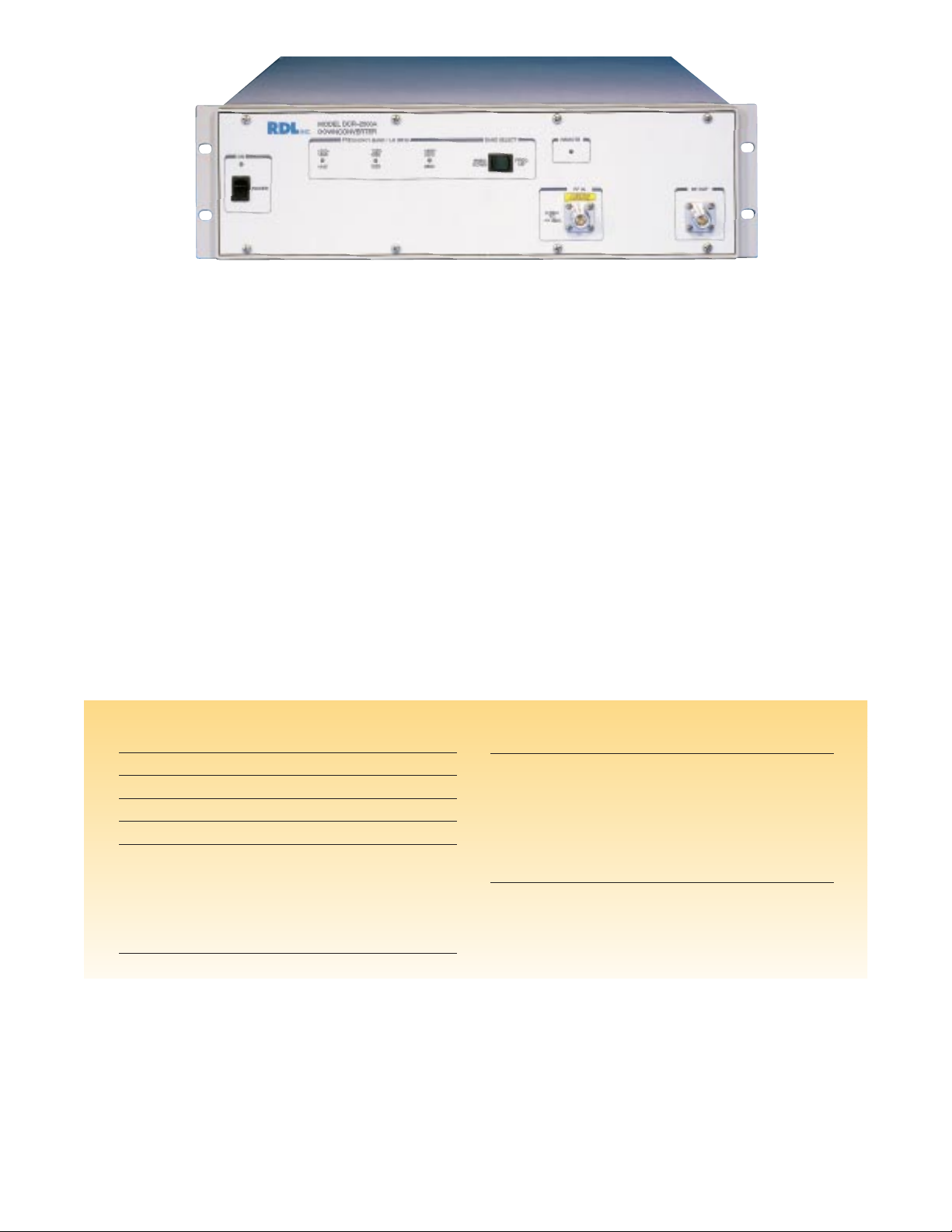
DCR–2500A Downconverter
Page 9

Frequency Generation and Noise Measurement for Critical Applications
7th Ave. & Freedley St. •Conshohocken, PA 19428
610-825-3750 •Fax 610-825-3530 •www.rdl-instrumentation.com
Applications
Measuring Crystal
Oscillator Phase Noise
Multiplying increases the phase
noise by 6 dB for every doubling.
Multiplying by x16 would increase
the phase noise by 24 dB and
increase (improve) the apparent
noise floor of the NTS/DCR to –129
dBc at 1 kHz offset and
–154 dBc at 10 kHz offset.
Measuring Signals
Above 14 GHz
Option 01 provides a very
low noise source for mixing
down from higher frequencies. The user can mix down
signals as high as 25 GHz
to within the range of the
DCR-14000A using this
option.
Measuring Additive
Phase Noise
The DCR-14000A with Option
02 can be a microwave source
that has extremely low phase
noise. In “Source” mode the
internal LOs are made available
to drive a microwave downconverter or microwave amplifier
so that the phase noise of the
output can be measured directly by the NTS-1000B or another
DCR-14000A/ NTS-1000B.
1503800-991-Rev-
 Loading...