

Page 1
DCR-2500A SPECIFICATIONS
Frequency Range:
1 to 3.26 GHz
Input Level Range 0 to –10 dBm
Output Frequency Range 60 to 700 MHz
Output Conversion Gain: 3 dB;
± 3 dB
Typical Noise Floor dBc/Hz SSB @ 0 dBm input level
Offset 100Hz 1 kHz 10 kHz 100 kHz 300kHz 1 MHz
Bands
1.00-1.38 GHz –106 –134 –145 –154 –154 –155
1.38-1.86 GHz –105 –132 –143 –153 –154 –154
1.86-3.26 GHz –103 –130 –140 –151 –153 –154
General Data:
Remote Control: IEEE-488.2
AC Power: 99-121 and 198-242 Volts, 47-63 Hz
EMC: Meets the requirements of CE and
FCC Part 15.
Size: 20 x 17.5 x 5.25 inch (D x W x H)
Weight: 32lbs. net, 42lbs. shipping
1503450-300
Specifications subject to change without notice.
The requirement for phase noise levels in the new
PCS applications is unprecedented. The DCR-2500A
has the lowest noise available and the levels are low
enough, when combined with the NTS-1000B, to
measure these extremely low levels.
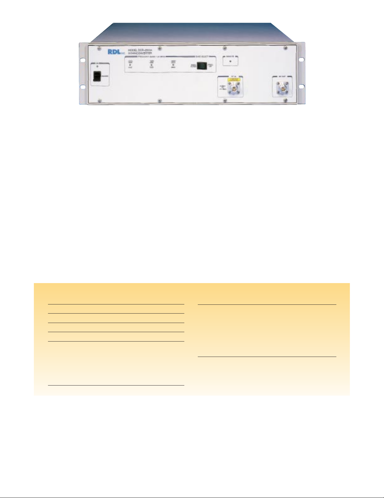
The RDL Model DCR-2500A is a unique downconverter in that the LOs inside have extremely low
phase noise. There are three overlapping bands in
the DCR-2500A that provide continuous frequency
coverage between 1 GHz and 3.26 GHz. The output
frequency range is bandpass filter limited to
between 60 and 700 MHz.
This unit requires only a 0 dBm input level. RDL
puts the gain inside the DCR-2500A so that an
external low-noise amplifier is not required.
Conversion gain is a nominal +3 dB and the DCR2500A output is sufficient to drive the Model NTS1000B Phase Noise Analyzer.
The DCR-2500A operates under IEEE-488.2 external control. The user can select a band or just send
a frequency and the DCR-2500A will automatically
select the correct band. The NTS-1000B has an
input screen, also available over the IEEE-488 bus,
that inputs the downconverter’s LO frequency. This
allows the NTS-1000B to properly interpret its
input to display the correct measured frequency.
The DCR-2500A extends the measurement speed
and convenience of the NTS-1000B into the PCS
frequency bands.
DCR–2500A Downconverter
Page 2
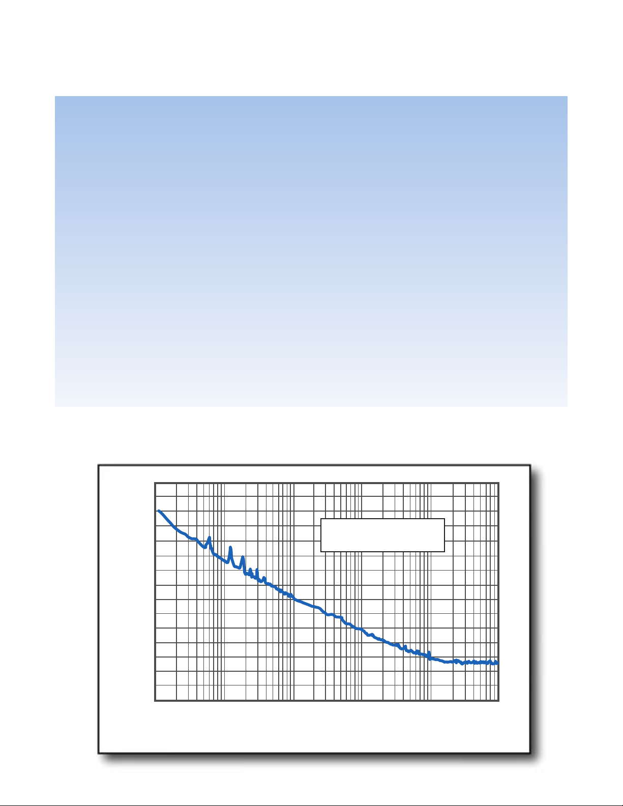
Input Frequency
2083.9 MHz
NTS–1000B and DCR–2500A
The new PCS applications have placed high
demands on the designer and manufacturer. The
constant push to better utilize the available spectrum has made phase noise one of the most important parameters. Phase synchronous modulation
has placed further demands on this critical parameter. Since every dB is critical and costly, accurate
measurement is now a requirement, not a luxury.
The RDL Phase Noise Analyzer System that consists
of the NTS-1000B and DCR-2500A provides unique
measurement capabilities that are not available
from other suppliers. The ability of the NTS-1000B
to measure unlocked sources, in seconds, combined
with the very low phase noise in the DCR-2500A
Downconverter extends the measurement of phase
noise from the lab into the factory.
In the past phase noise measurements have been
confined to the laboratory due to the complexity of
the measurement techniques and the time consum-
ing tools that have been available. The RDL
System makes this a push-button measurement
that can be made by non-technical personnel or
under IEEE bus control. The built-in printer port
and easy data manipulation makes documenting
phase noise measurements a snap, and for the
first time, makes statistical process control of this
critical parameter feasible.
The low noise floor of the RDL System opens up
the possibility of really measuring what is going
on in a synthesizer’s design. Now the noise of the
PLL can be separated from the noise of the VCO
and real design improvements can be analyzed
and implemented.
Now you don’t have to specify an over-designed
VCO and pay for performance you can not confirm
or use. The RDL System is so simple and fast that,
for the first time, you can consider testing every
product in production.
Typical Noise Floor NTS-1000B and DCR-2500A
(Corrected for Source Noise)
–30
–40
–50
–60
–70
–80
–90
–100
–110
–120
–130
Noise (dBc/Hz) SSB
–140
–150
–160
–170
–180
10 100 1,000 10,000
Offset Frequency (Hz)
100,000 1,000,000
 Loading...