

Page 1
For the very latest specifications visit www.aeroflex.com
6820A Series Microwave Scalar Analyzers for fast and accurate testing in field and factory
Microwave
6820A Series RF & Microwave Scalar Analyzer
• Precision scalar network measurements
• 3 GHz, 8.4 GHz, 20 GHz, 24 GHz,
40 GHz and 46 GHz frequency versions
• Low noise synthesized signal source with
optional step attenuator
• Internal modulation options - pulse
modulator and/or FM and pulse
generator
• Real time transmission line fault location
with 0.1% accuracy
• EEPROM corrected scalar detectors for
accurate measurements
• Applications interface allows guided and
automatic testing
• Modular design for rapid service
Five Frequency Versions
The 6820 series of scalar analyzers covers the
most commonly required frequency bands in 5
versions. A comprehensive range of accessories is
available to support each of these units.
6820A series Scalar Analyzers
6821A 1 MHz to 3 GHz Scalar Analyzer
6822A 10 MHz to 8.4 GHz Scalar Analyzer
6823A 10 MHz to 20 GHz Scalar Analyzer
6824A 10 MHz to 24 GHz Scalar Analyzer
6825A 10 MHz to 46 GHz Scalar Analyzer
6825AR 10 MHz to 40 GHz Scalar Analyzer
Synthesized Source
The synthesized source has low phase noise and
1 Hz frequency resolution. VCOs are used for frequencies above 3
GHz and an integrated RF synthesizer for the 1 MHz to 3 GHz
range. Optionally increased output power is available from 3 to 24
GHz. Internal filtering results in excellent harmonic performance of
<-50 dBc (70 MHz to 24 GHz) for improved scalar measurement
accuracy. Optional step attenuators are available to set low output
powers for amplifier or receiver testing.
In CW mode the source can be used for local oscillator substitution.
A power sweep is provided for amplifier gain compression testing.
External FM can be applied by connecting an AF generator to the
rear panel. The internal modualtion option provides frequency
modulation of the source or pulse patterns for internal or external
pulse modulators. The internal pulse modulator option allows either
an external pulse generator to be connected via a rear panel BNC
connector or utilizes the pulse patterns available from the internal
modulation option. The pulse patterns may be configured and
selected in either single pulse or multi-pulse formats.
When used with the scalar analyzer the source provides a swept
synthesized output for frequency characterization of components
and systems.
Scalar Analyzer
The three input scalar analyzer provides network characterization of
components and systems. Simultaneous measurement of insertion
and return loss are displayed on the 6820 color screen. Excellent
measurement accuracy is assured by the use of EEPROM corrected
detectors.
Page 2
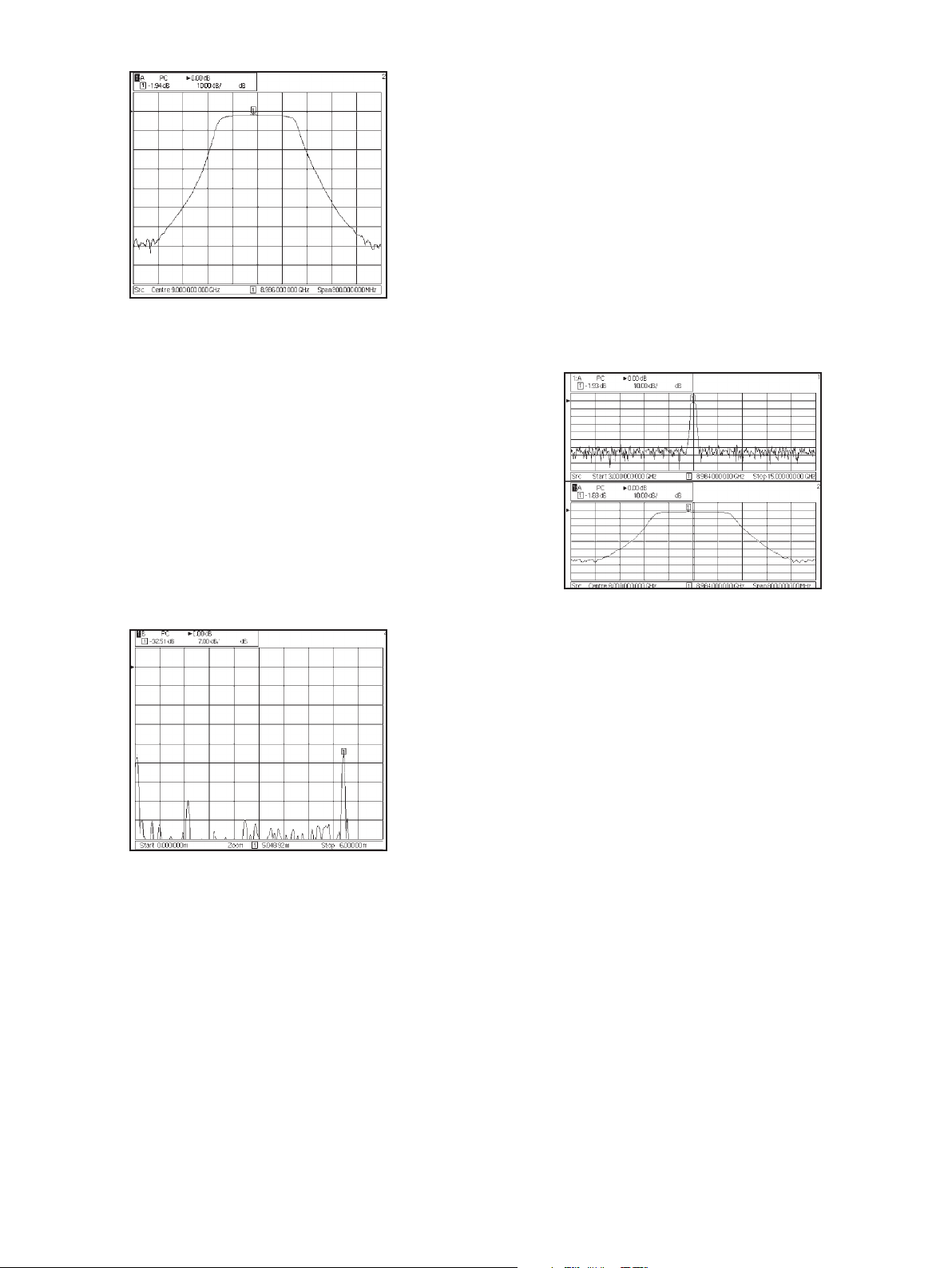
Bandpass filter insertion loss measurement
Each detector is individually characterized for linearity and
frequency response to provide a measurement accuracy close to that
achieved with a power sensor. A range of autotesters with high directivity is available for return loss measurements.
Fault Location
Fault location software is standard on all 6820A series instruments.
Many modern communication systems rely on a coaxial or waveguide
feed between the transmitter and antenna. The fast fault location
facility of the 6820A can quickly locate the position of faults causing
poor return loss in the feed, which can seriously impact system performance.
Measurement resolution and accuracy is assured by the use of a synthesized source with up to 1601 measurement points.
Fault location measurement of a coaxial feed and antenna
Simplified User Interface
Integration of the source and scalar analyzer, and the built-in applications facility, makes operations faster and simpler. The operator uses
a single interface to set up any measurement. This saves time and is
easier than writing software to perform comprehensive network
measurements.
Eight softkeys give rapid access to all commonly used parameters.
Softkeys are shaped to inform the user of the action that the key will
perform, e.g. enter data, select from list, move to another menu or
immediate action. All commonly accessed functions are no more than
one level deep, so that the instrument operation is easily learned.
Applications Interface
An applications interface is built into the 6820A series which allows
the user to create their own measurement routines and guide the
operator through the test procedure. For example it can display on the
6820A screen how to set up the measurement, lead the operator
through a calibration, show where to connect the device under test
and then test the device’s performance against predefined limits. The
applications facility can reduce the incidence of operator error,
improve measurement repeatability, provide guidance to infrequent
users or simplify complex test procedures.
Color Display
A large TFT color display is fitted to the 6820A displaying up to four
measurements on two channels. Scalar measurements can be
displayed simultaneously on independent channels.
Dual channel display, showing wide band and narrow band fre-
quency sweeps
Comprehensive Markers
Up to eight markers are available. The marker menus provide the
tools that are most commonly used in each of the measurement
modes.
In scalar mode markers automatically calculate peak to peak ripple,
N-dB bandwidth, -1 dB bandwidth and find maximum and minimum
signal levels. This simplifies device characterization and reduces test
time.
For fault location measurements the next peak left/right feature
identifies the position and magnitude of each of the discontinuities
along the transmission line. The peak find softkey quickly locates the
biggest discontinuity on the line.
Fast Field Repair
6820A has a modular architecture with modules slotted onto a
common mother board. In the event of a module failure the instrument can be repaired by module replacement to reduce instrument
downtime. Following a repair, software routines realign the replaced
module.
Page 3

For the very latest specifications visit www.aeroflex.com
Manufacturing Test
To the production manager the 6820A offers reduced programming
time, reduced test time and simplified archiving of results. 6820A is
fully compliant with the IEEE 488.2 GPIB standard. A full 401 data
points can be transferred over the GPIB in typically <50 ms.
Individual data points can be repetitively read in typically 10 ms. This
enables full results archiving with minimal time penalty.
Continuity of test is essential in a production environment. A failed
test system can result in expensive loss of output. 6820A with its field
replaceable modules minimizes any output loss due to test system
failure.
Installing and Maintaining Systems
During the installation period of a microwave system it is always necessary to revalidate key parameters. 6820A provides a comprehensive
solution for installation teams. It is housed in a ruggedized case, has
secure handles and can be supplied with a protective carrying case.
For systems with long waveguide or coaxial feeds the 6820 is used by
the installation team to measure return loss and if necessary fault
location. The synthesized source with 1601 measurement points
ensures precise fault location measurements. AC Detection can be
used for return loss and fault location measurements in the presence
of interfering signals, a common cause of poor measurement performance in the field. In this mode the source output is chopped and
the resulting pulsed signal is demodulated and processed in such a
way that interference and zero drift are effectively cancelled.
By archiving results to external USB Flash Memory, or the internal
instrument memory, the 6820A forms the basis of a preventative
maintenance system. Experience shows that degradation in the
antenna feed is the major source of system field failures. 6820A has
the accuracy to monitor and identify gradual system degradation with
time.
Additionally, the synthesized microwave source may be used in conjunction with the optional step attenuators, to carry out system sensitivity tests. The internal pulse modulator and modulation options
with both single pulse and multi-pulse capability offers the ability to
perform tangential sensitivity and range tests for many different types
of radar systems
Results Logging and Outputting
Measurement results can either be saved to internal non-volatile
memory or to USB Flash Memory. Traces saved vis USB can then
be archived or imported into a spreadsheet for viewing.
SPECIFICATION
SOURCE
Functionality
Synthesized CW
Synthesized sweeper for use with scalar analyzer
CW Power sweep
External FM Modulation
Internal FM + Pulse driver (Option 23)
Internal Pulse Modulator (Option 25)
Frequency Range
6821A 1 MHz to 3 GHz
6822A 10 MHz to 8.4 GHz
6823A 10 MHz to 20 GHz
6824A 10 MHz to 24 GHz
6825A 10 MHz to 46 GHz
6825AR 10 MHz to 40 GHz
Resolution (Settable)
1 Hz to 46 GHz
CW Accuracy
(Frequency Standard error x Frequency) ± 10 Hz
Swept Accuracy (Typical)
300
µ
s Step Time
1 MHz to 3 GHz <20 kHz
3 GHz to 46 GHz <200 kHz
1 ms Step Time
1 MHz to 3 GHz <1 kHz
3 GHz to 46 GHz <10 kHz
10 ms Step Time
1 MHz to 3 GHz <100 Hz
3 GHz to 46 GHz <1 kHz
Levelled Power Range
6821A/2/3/4 standard
1 MHz to 3 GHz -10 dBm to +10 dBm
3 GHz to 24 GHz -10 dBm to +5 dBm
6825A & 6825AR
10 MHz to 8 GHz -10 dBm to +8 dBm +10 dBm typ
8 GHz to 20 GHz -10 dBm to +5 dBm +7 dBm typ
20 GHz to 24 GHz -10 dBm to +4 dBm +6 dBm typ
24 GHz to 40 GHz -10 dBm to 0 dBm +3 dBm typ
40 GHz to 46 GHz -10 dBm to 0 dBm typ*
* Excluding the effect of connector moding
6822A/3/4 + option 030 (higher power)
1 MHz to 24 GHz -10 dBm to +10 dBm
6821A + option 010 (110 dB Step Attenuator)
1 MHz to 3 GHz -120 dBm to +8 dBm
6822A/3 + option 011 (70 dB Step Attenuator)
10 MHz to 3 GHz -80 dBm to +8 dBm
3 GHz to 20 GHz -80 dBm to +2 dBm
+ option 030 (higher power)
3 GHz to 20 GHz -80 dBm to +7 dBm
6822A/3/4 + option 012 (90 dB Step Attenuator)
10 MHz to 3 GHz -100 dBm to +8 dBm
3 GHz to 24 GHz -100 dBm to +2 dBm
+ option 030 (higher power)
3 GHz to 24 GHz -100 dBm to +7 dBm
6825A & 6825AR + Option 013 (70 dB Step Attenuator)
Page 4

10 MHz to 8 GHz -80 dBm to +6 dBm +8 dBm typ
8 GHz to 20 GHz -80 dBm to +2 dBm +4 dBm typ
20 GHz to 24 GHz -80 dBm to +1 dBm +3 dBm typ
24 GHz to 40 GHz -80 dBm to -3 dBm 0 dBm typ
Note: 1. For option 002 (Field Replaceable connectors) guaranteed
levelled output is reduced by 0.5 dB
2. For option 025, (internal pulse modulator) the guaranteed levelled
output is reduced as the option specification.
Settable Power Resolution
0.01 dB
Power Sweep Range (from Maximum Levelled Power) Without Attenuator
>20 dB (except when option 025, internal pulse modulation is fitted)
Internal Levelling Accuracy at 0 dBm (no options fitted, option 030)
1 MHz to 3 GHz, ±0.7 dB
3 GHz to 24 GHz, ±1.0 dB
24 GHz to 40 GHz, ±1.5 dB
Levelled Power Accuracy With Options 010, 012, 013
1 MHz to 3 GHz
<±1 dB (±0.3 dB or 2% of attenuator setting dB whichever is
greater)
3 GHz to 24 GHz
<±1 dB (±1 dB or 4% of attenuator setting in dB whichever is
greater)
24 GHz to 40 GHz
<±1.5 dB (±1.0 dB or 4% of attenuator setting in dB whichever is
greater)
Linearity (No Options Fitted, Option 030) Over Levelled Power Range
Relative to 0 dBm
1 MHz to 40 GHz <±0.5 dB
Power Stability With Temperature (Typical)
1 MHz to 40 GHz <0.1 dB/°C
Harmonics and Sub-Harmonics Over Levelled Power Range Harmonics
<70 MHz, <-25 dBc
70 MHz to 3 GHz, <-55 dBc
3GHz to 24GHz <-50 dBc
24 GHz to 40 GHz, <-20 dBc
Sub-Harmonics
10 MHz to 3 GHz <-60 dBc
3 GHz to 24 GHz None
24 GHz to 40 GHz <-40 dBc
Spurious Signals (Typical)
For carrier frequencies<375 MHz
Offset:
30 kHZ to 150 kHZ, <-50 dBc
>150KHz <-55dBc
For carrier frequencies>375 MHz
Offset:
30 kHz to 150 kHz, <-50 dBc
>150KHz <-60dBc
Phase Noise <dBc/Hz in CW mode
CW Freq Frequency offset
1 kHz 10 kHz 100kHz
0.25 GHz -86 -95 -108
0.5 GHz -98 -112 -134
1 GHZ -92 -106 -128
2 GHz -86 -100 -122
4 GHz -80 -92 -100
10 GHz -72 -84 -90
20 GHz -66 -78 -82
24 GHz -64 -76 -80
40 GHz -63 -75 -79
Source Match (Typical)
1 MHz to 3 GHz , <-15 dB
3 GHz to 20 GHz, <-10 dB
20 GHz to 40 GHz, <-8 dB
Output Connector
6821A/2/3; Precision N Type, female
6824A: Precision 3.5 mm, female
6825A: Precision 2.92 mm female
or optional field replaceable connectors
Modulation
External Frequency Modulation
Peak deviation (1 V peak input)
10 MHz - 375 MHz 1 kHz to 5 MHz
375 MHz - 750 MHz 250 Hz to 1.25 MHz
750 MHz - 1.5 GHz 500 Hz to 2.5 MHz
1.5 GHz - 3 GHz 1 kHz to 5 MHz
3 GHz - 46 GHz 20 kHz to 1 MHz
Accuracy (1 kHz modulating frequency) 20-400 kHz deviation
±3 % of indication ±1 Hz excluding residual FM
-3 dB bandwidth, AC coupled mode
10 MHz - 3 GHz <100 Hz to >1 MHz typical
3 GHz - 46 GHz <100 Hz to >500 kHz typical
-3 dB bandwidth, DC coupled mode
10 MHz - 3 GHz DC to >1 MHz typical
3 GHz - 46 GHz DC to >500 kHz typical
Option 023 Internal Modulation Generator
FM Source
Modulation signal sinewave, 0.1 Hz to 500 kHz, resolution 0.1 Hz
Other specifications as for External Frequency Modulation except:
Accuracy (1 kHz modulating frequency) 20-400 kHz deviation ±5 % of
indication ±1 Hz excluding residual FM
Pulse Generator Source
Modes Single Pulse, Pulse Pattern
Pulse Pattern Pulse patterns comprising up to 256
pulse width/ PRI pairs can be set up,
stored and recalled
Trigger Modes External, Internal continuous
Pulse Widths (PW) 120 ns to >1 second
Resolution 120 ns
Pulse Period (PRI) 240ns to 7 seconds (PRF <1 Hz to
4.16 MHz)
Resolution 120 ns
Pulse Delay Zero to 100 ms where zero is <120 ns
referred to trigger or sync pulse falling
edge
Resolution 120 ns
Sync Output 120 ns pulse referred to trigger. Available
at trigger socket
Inputs/Outputs
Trigger in/out Rear panel BNC connector provides
Page 5

For the very latest specifications visit www.aeroflex.com
either trigger input or sync output dependant upon trigger mode. TTL level
Options 025a & 025b Internal Pulse Modulator
Option 25a (6822A and 6823A)
Frequency Range 50 MHz to 18 GHz (8.4 GHz for 6822A)
Usable to 20GHz
RF Output Range The levelled power range is reduced by:
<3.5 dB up to 6 GHz
<4.5 dB up to 14 GHz
<5.0 dB up to 18 GHz
when pulse modulation is selected
RF Level Accuracy Adds ± 0.3 dB to the levelled power
accuracy specification when pulse
modulation is enabled and for powers of
< -1 dBm
Source Harmonics (with Pulse Modulation enabled)
50 MHz - 2 GHz <-35 dBc
2 GHz - 20 GHz <-50 dBc
On/Off Ratio
50 MHz - 1 GHz >55 dB
1 GHz - 9 GHz >60 dB
9 GHz - 17 GHz >70 dB
17 GHz - 18 GHz >80 dB
18GHz - 20GHz >80 dB (typical)
Rise/Fall Times (measured at 10% and 90%)
Rise Time <8 ns (Typically < 5 ns)
Fall Time <12 ns (Typically < 9 ns)
Option 25b (6824A, 6825A and 6825AR)
Frequency Range 50 MHz to 40 GHz (24 GHz for 6824A)
(46 GHz for 6825A)
RF Output Range The levelled power range is reduced by:
<5 dB up to 20 GHz
<8 dB up to 30 GHz
<9 dB up to 40 GHz
when pulse modulation is selected
RF Level Accuracy Adds ± 0.3 dB to the levelled power accuracy
specification when pulse modulation is enabled and for output powers
of <-3 dBm
Source Harmonics (with Pulse Modulation enabled)
50 MHz - 375 MHz <-35 dBc
375 MHz - 24 GHz <-50 dBc
24 GHz - 40 GHz <-20 dBc
On/Off Ratio
50 MHz - 10 GHz >60 dB
10 GHz - 26.5 GHz >60 dB (typically > 70 dB)
26.5 GHz - 40 GHz >60 dB (typically > 80 dB)
Rise/Fall Times (measured at 10% and 90% of edge)
Rise Time <7 ns (Typically < 6 ns)
Fall Time <11 ns (Typically < 10 ns)
Pulse Modulation Control
Modes
Pulse, Pulse CW
External (via rear panel BNC connector)
Internal (if Opt 23 fitted)
Control
Control of pulse modulation is:
Internal via soft key menu when the modulation generator
option (Opt 023) is fitted or
External via the rear panel BNC Mod in/out socket.
Level is TTL, High = On, Low = Off.
When pulse mod Off is selected the output is the selected CW
output level
Pulse CW In both internal or external modes, allows setting of
output Level in the 'On' condition for reference or
calibration.
SCALAR ANALYZER
SYSTEM FEATURES
Frequency Range
As per source frequency range
Number of Inputs
3 detector inputs
Number of Measurement Points
User selectable from 2 to 1601
Applications
Return loss vs frequency
Insertion loss vs frequency
Fault Location
Voltage vs frequency
Detection Modes
AC and DC
Noise Reduction
Averaging, 1 to 1000
Smoothing, 0.01 to 20%
Power Measurements
Using scalar detectors
Detector Correction
Frequency response and linearity read from EEPROM for 6230A/L and
fault locators.
Support for 6230 and autotesters.
INSERTION LOSS MEASUREMENTS
Measurement Dynamic Range, AC Scalar Detection, with 623XA
Detector
Max source output to -60 dBm
Max source output to -65 dBm (with averaging)
Typical values:
>65 dB (10 MHz to 40 GHz)
>75 dB (1 MHz to 3 GHz) only with 6232A
Measurement Update Rate
401 points in 270 ms with DC detection
Calibration
Through path calibration or short and short/open calibrations for single
ended insertion loss
Inputs
Single input or ratio
Accuracy
Linearity + mismatch
Linearity (applies after normalization)
Linearity (for Power Levels >-50 dBm)
±0.2 dB / 10 dB but not >0.5 dB in total
Page 6

RETURN LOSS MEASUREMENTS
Measurement Update Rate
401 points in 270 ms with DC detection
Calibration
Short, Open, Short/Open
Inputs
Single input or ratio
Accuracy
Linearity + directivity + test port mismatch
Linearity (for Power Levels >-45 dBm)
±0.2 dB / 10 dB but not > 0.5 dB in total
FAULT LOCATION MEASUREMENTS
Measurement Range
Up to 25 km depending on cable or waveguide loss
Units
Feet or meters
Number of Measurement Points
User selectable from 50 to 1601
Minimum Resolution
For two equal amplitude discontinuities using maximum sweep width
6821A: 12.18 x Vr cm
6822A: 4.32 x Vr cm
6823A: 1.82 x Vr cm
6824A: 1.51 x Vr cm
6825A: 0.91 x Vr cm
where Vr is the relative velocity factor for the transmission line
Measurement Update Rate
512 points in 250 ms, DC detection
Dynamic Range
DC detection 70 dB
AC detection 80 dB
Distance Accuracy
3 mm or 0.1% of range for a single fault
Transmission Line Database
Data supplied as standard
Required Accessory
624X series fault locator or 658X series transmission line test head or
accessory power divider (see optional accessories)
FREQUENCY STANDARD
Internal 10 MHz OCXO
Drift
±5 in 108over 0 to 55°C
Ageing
±2 in 10
7
per year (OCXO)
External Frequency Standard
1 MHz or 10 MHz, Connector: BNC
REAR PANEL CONNECTORS
RS-232
9 way D-type connector, male
Baud rate 300 to 9600
GPIB Interface
GPIB is IEEE 488.1 and 488.2 compatible. The interface has 2 functions.
-Instrument control with full Talk/Listen capability
-Control of plotter using HPGL. Plotter is buffered to permit measure-
ments to proceed whilst plotting.
Frequency Standard In/Out BNC
1 MHz or 10 MHz input or 10 MHz output selectable from front panel
Mod In/Out BNC
Mod in/out
Rear panel BNC connector, TTL level. Impedance approx 100
Ω
Printer Outputs
USB (Front Panel) or 25 way D-type connector Parallel Interface
External Monitor
Standard VGA, 640 by 480 color output
15 way high density D-type female connector
Voltage Output
Auxiliary 9-pin connector
Settable for 0 to 10 V ramp, fixed voltage or chart recorder drive
External Levelling Input
Input voltage range: 0 to +1 V
Connector: BNC
GENERAL FEATURES
Number of Display Channels
2
Number of Measurements
4 (2 per display channel)
Number of Measurement Points
2 to 1601 for one trace, scalar
Display
Color active matrix TFT liquid crystal display with 16.5 cm (6.5 in)
visible diagonal
Data Storage
USB Flash Memory
MARKERS
8 per trace plus separate delta marker
Marker Functions
Marker, delta marker, minimum, maximum, search left, search right,
N-dB bandwidth (with center frequency), marker tracking.
Scalar Analyzer
Active marker Max / Min
Max / Min Tracking
Find PK-PK
PK-PK Tracking
Search Right / Left
Page 7

For the very latest specifications visit www.aeroflex.com
Bandwidth / Optional CF / DF (Q)
dB / Octave, dB / Decade Readout
Delta Marker On / Off
-1 dB gain compression
Fault Location
Find Max / Track Max
Next PK Right / Left
Set PK Level
Delta marker On / Off
General
Marker Table
Assign Active MKR / Position Active MKR
Set-up Markers (i.e. On / Off, Position)
Large Readout
All Off
Marker Resolution
Frequency: 6 digits or 1 Hz, user selectable
Power: 0.01 dB
Voltage: 1 nV
Measurement Manipulation
Display live measurement.
Display trace memory.
Display live measurement relative to trace memory.
Measurement hold may be applied for each trace.
Any input or ratio of inputs may be assigned to any one or more than
one trace(s). A trace may display absolute power, power relative to a
path calibration or power minus a trace memory.
Input Offsets
An offset in the range -99.99 dB to +99.99 dB in 0.01 dB steps may
be applied per detector input.
Weight - Variant and Option Dependent
16 kg (35 Ibs)
Size (Not including front handles)
230 mm H x 430 mm W x 570 mm D
9 in H x 17 in W x 22 in D
Power Supply
100-240 V~ (Limit 90-264 V~)
50-60 Hz (Limit 45-66 Hz)
108-118 V~ (Limit 90-132 V~)
50-400Hz (Limit 45-440 Hz)
200 W maximum
Rated Range of Use
Temperature 0 to 50°C
6825A and 6825AR only +5°C to 45°C only
Humidity Up to 93% RH at 40°C
Conditions of Storage and Transportation
Temperature -40 to +71°C
Humidity Up to 93% RH at 40°C
Altitude Up to 4570 m (15000 ft)
ELECTROMAGNETIC COMPATIBILITY
Conforms to the protection requirements of EEC Council directive
2004/108/EC.
Conforms to the limits specified in the following standards:
IEC/EN61326-1 : 2006
RF Emission Class A, Immunity table 3.
The radiated RF emission from this equipment is below Class A (reference CISPR 11). Class A equipment is intended for use in industrial
environments. There may be potential difficulties in ensuring electromagnetic compatibility in other environments due to radiated disturbances.
When using a 6230L detector, the noise floor may increase if exposed
to a conducted RF disturbance level of >1.5V.
SAFETY
Conforms with the requirements of EC Council Directive 2006/95/EC
(as amended) and the product safety standard IEC/EN 61010-1 :
2001 + C1 : 2002 + C2 : 2003 for class 1 portable equipment, for
use in a Pollution Degree 2 environment. The instrument is designed to
operate from an Installation Category 2 supply.
Page 8

VERSIONS AND OPTIONS
When ordering please quote the full ordering number information.
Ordering
Numbers Versions
6820A Scalar Analyzers
6821A 1 MHz to 3 GHz Scalar Analyzer
6822A 10 MHz to 8.4 GHz Scalar Analyzer
6823A 10 MHz to 20 GHz Scalar Analyzer
6824A 10 MHz to 24 GHz Scalar Analyzer
6825A 10 MHz to 46 GHz Scalar Analyzer
6825AR 10 MHz to 40 GHz Scalar Analyzer
Supplied Accessories
46886/067 CD-ROM containing:
46892/920 6820A/6840A Series Operating Manual
46892/922 6810A and 6820A/6840A Series Getting Started Guide
46892/921 6820A/6840A Series Remote Operating Manual
46892/932 6810A Series Operating/Remote Programming Manual
43123/076 AC Supply Lead
37591/755 Front Panel Cover
Options
002 Field Replaceable Precision N (f) or 3.5 mm (f) RF
Connectors for Source Output. (not available on 6821A)or
2.92 mm (f) RF connector for 6825A&6825AR
010 3 GHz 110 dB Step Attenuator (only available for 6821A)
011 20 GHz 70 dB Step Attenuator
(only available for 6822A/6823A)
012 26.5 GHz 90 dB Step Attenuator
(not available for 6821A/6825A/6825AR)
013 40 GHz 70 dB Step Attenuator (only available for
6825A & 6825AR)
023 Internal Modulation Generator (FM &Pulse)
025 Internal Pulse Modulator (Opt 25a 6822A/6823A), (Opt 25b
6824A/6825A/6825AR)
030 Higher Output Power (not applicable to
6821A/6825A/6825AR)
Complementary Product
6146 500 MHz to 18 GHz Pulse Modulator
54441/019 AC Power Supply for 6146
6147 70 MHz to 40 GHz Pulse Modulator
Note : All specifications quoted are for operation at calibration temperature ±3°C.
Specifications involving Type N connectors above 18 GHz are not traceable to
national standards as these do not exist at present.
Specifications involving 2.92 mm connectors above 40 GHz are not traceable to
national standards as these do not exist at present.
Typical specifications are non-warranted.
Guided Applications not available at launch.
ACCESSORIES
6230A/L SCALAR DETECTORS
6230A series Standard Detectors (-65 dBm to +20 dBm) typical
6230A 10 MHz to 20 GHz, N type (m)
6232A 1 MHz to 3 GHz, N Type (m)
6233A 10 MHz to 26.5 GHz, 3.5 mm (m)
6234A 10 MHz to 46 GHz, 2.92 mm (m)
6230L series Low VSWR detectors (-59 dBm to +26 dBm typical)
6230L 10 MHz to 20 GHz, N type (m)
6233L 10 MHz to 26.5 GHz, 3.5 mm (m)
6234L 10 MHz to 46 GHz, 2.92 mm (m)
AUTOTESTERS AND RF BRIDGE
Autotesters
59999/158 10 MHz to 18 GHz N (m)
59999/159 10 MHz to 18 GHz N (f)
59999/168 10 MHz to 40 GHz 2.92 mm (m)
59999/169 10 MHz to 40 GHz 2.92 mm (f)
RF Bridge
59999/170 5 MHz to 2 GHz N (f)
FAULT LOCATORS
Fault Locators
6242F 10 MHz to 3 GHz, N (f)
6242M 10 MHz to 3 GHz, N (m)
6240F 10 MHz to 20 GHz, N (f)
6240M 10 MHz to 20 GHz, N (m)
6243F 10 MHz to 26.5 GHz, 3.5 mm (f)
6243M 10 MHz to 26.5 GHz, 3.5 mm (m)
6241 10 MHz to 20 GHz, 7 mm
Microwave Ruggedized Cables for Fault
Locators
54311/197 1.5 m, 18 GHz, N (m) to Right Angle N (m)
54311/198 3.0 m, 18 GHz, N (m) to Right Angle N (m)
54311/201 1.5 m, 26.5 GHz, 3.5 mm (m) to Right Angle 3.5 mm (m)
54311/202 3.0 m, 26.5 GHz, 3.5 mm (m) to Right Angle 3.5 mm (m)
RF Ruggedized Cables for Fault Locators
54311/199 1.5 m, 3 GHz, N (m) to Right Angle N (m)
54311/200 3.0 m, 3 GHz, N (m) to Right Angle N (m)
Microwave Ruggedized Cables
54311/116 1.5 m, 20 GHz, N (m) to N (m)
54311/109 3.0 m, 20 GHz, N (m) to N (m)
54311/117 1.5 m, 26.5 GHz, 3.5 mm (m) to 3.5 mm (m)
54311/110 3.0 m, 26.5 GHz, 3.5 mm (m) to 3.5 mm (m)
Fault Locator and Scalar Detector DC Cables
43139/099 1.5 m, DC Cable
43139/100 3.0 m, DC Cable
43139/101 10 m, DC Cable
43139/102 25 m, DC Cable
43139/103 50 m, DC Cable
Page 9

For the very latest specifications visit www.aeroflex.com
ACCESSORIES
Power Splitters/Dividers
54311/123 Power Splitter DC to 18 GHz, Type N
54311/124 Power Splitter DC to 26.5 GHz, 3.5 mm
54311/161 Power Splitter DC to 40 GHz, 2.92 mm
54311/187 Power Divider DC to 18 GHz
54311/188 Power Divider DC to 26.5 GHz
RF Ruggedized Cables for Bridges and Dividers
54311/195 1.5 m, 3 GHz, N (m) to N (m)
54311/196 3.0 m, 3 GHz, N (m) to N (m)
Fixed Loads
54421/020 7 mm Fixed Load
54421/021 3.5 mm (f) Fixed Load
54421/022 3.5 mm (m) Fixed Load
54421/023 N (m) Fixed Load
54421/024 N (f) Fixed Load
Precision Adapters
54311/175 N (m) to N (m)
54311/167 N (m) to N (f)
54311/174 N (f) to N (f)
54311/176 N (f) to 3.5 mm (f)
54311/177 N (m) to 3.5 mm (f)
54311/178 N (m) to 3.5 mm (m)
54311/185 N (f) to 3.5 mm (m)
54311/137 N (m) to TNC (f)
54311/138 N (m) to TNC (m)
54311/139 N (f) to TNC (f)
54311/186 N (f) to TNC (m)
54311/203 7 mm to N (f)
54311/204 7 mm to TNC (m)
54311/205 7 mm to TNC (f)
54311/136 TNC (m) to TNC (m)
54311/107 3.5 mm (f) to 3.5 mm (f)
54311/165 3.5 mm (m) to 3.5 mm (f)
54311/164 3.5 mm (m) to 3.5 mm (m)
54311/162 2.92 mm (m) to 2.92 mm (m)
54311/206 2.92 mm (m) to 2.92 mm (f)
54311/207 2.92 mm (f) to 2.92 mm (f)
Standard Adapters
54311/133 N (f) to SMA (f)
54311/134 N (m) to SMA (f)
54311/135 TNC (m) to SMA (m)
Miscellaneous Electrical Cables
54311/170 Positive Voltage Measurement Cable
54311/112 Negative Voltage Measurement Cable
43129/189 GPIB Cable
43139/042 BNC (m) to BNC (m) 1.5 m
46884/560 Parallel Printer Interface Cable
43137/604 Autotester Adapter Cable 0.5 m
43139/104 Autotester Adapter Cable 1.5 m
Standard Microwave Cables
54351/022 0.5 m, 18 GHz, N (m) to N (m)
54351/025 0.5 m, 26.5 GHz, 3.5 mm (m) to 3.5 mm (m)
54351/027 0.5 m, 40 GHz, 2.92 mm (m) to 2.92 mm (m)
Attenuators
56534/901 Precision Fixed Coaxial Attenuator 3 dB DC to 18 GHz 5 W,
N(m) to N(f)
56534/902 Precision Fixed Coaxial Attenuator 6 dB DC to 18 GHz 5 W,
N(m) to N(f)
56534/903 Precision Fixed Coaxial Attenuator 10 dB DC to 18 GHz 5 W,
N(m) to N(f)
56534/904 Precision Fixed Coaxial Attenuator 20 dB DC to 18 GHz 5 W,
N(m) to N(f)
Software Support
59000/371 Guided Scalar Measurements
MISCELLANEOUS
46885/038 Rack Mount Kit for 6800A Series
46880/122 Series Manual (consists of maintenance manual (printed)+
operating manual (CD-ROM))
46882/920 6820A/6840A Series Operating Manual
46882/922 6810A and 6820A/6840A Series Getting Started Guide
(printed)
46882/921 6820A/6840A Series Remote Operating Manual (printed)
84501 Soft Carrying Case
46662/695 Flight Case
54152/001 3.5 mm Torque Wrench
54211/008 Compact Keyboard
Distributed by:
www.SignalTestInc.com <http://www.SignalTestInc.com>
1529 Santiago Ridge Way
San Diego, CA 92154 USA.
Sales@SignalTestInc.com
Page 10

Page 11

For the very latest specifications visit www.aeroflex.com
Page 12

Part No. 46891/331, Issue 1, 10/08
CHINA Beijing
Tel: [+86] (10) 6539 1166
Fax: [+86] (10) 6539 1778
CHINA Shanghai
Tel: [+86] (21) 5109 5128
Fax: [+86] (21) 5150 6112
FINLAND
Tel: [+358] (9) 2709 5541
Fax: [+358] (9) 804 2441
FRANCE
Tel: [+33] 1 60 79 96 00
Fax: [+33] 1 60 77 69 22
GERMANY
Tel: [+49] 8131 2926-0
Fax: [+49] 8131 2926-130
HONG KONG
Tel: [+852] 2832 7988
Fax: [+852] 2834 5364
INDIA
Tel: [+91] 80 5115 4501
Fax: [+91] 80 5115 4502
KOREA
Tel: [+82] (2) 3424 2719
Fax: [+82] (2) 3424 8620
SCANDINAVIA
Tel: [+45] 9614 0045
Fax: [+45] 9614 0047
SPAIN
Tel: [+34] (91) 640 11 34
Fax: [+34] (91) 640 06 40
UK Cambridge
Tel: [+44] (0) 1763 262277
Fax: [+44] (0) 1763 285353
UK Stevenage
Tel: [+44] (0) 1438 742200
Fax: [+44] (0) 1438 727601
Freephone: 0800 282388
USA
Tel: [+1] (316) 522 4981
Fax: [+1] (316) 522 1360
Toll Free: 800 835 2352
www.aeroflex.com
info-test@aeroflex.com
As we are always seeking to improve our products,
the information in this document gives only a general
indication of the product capacity, performance and
suitability, none of which shall form part of any contract. We reserve the right to make design changes
without notice. All trademarks are acknowledged.
Parent company Aeroflex, Inc. ©Aeroflex 2008.
 Loading...