

Page 1

ATD-31167
1/2" X 50' RETRACTABLE
AIR HOSE REEL
Instruction Manual
Specifications
• Spring driven, automatic rewind, with locking ratchet mechanism (eight locking positions per
revolution).
• Brass connectors on hose and reel.
• 50 Feet of ½” rubber Hose
• Incoming Air Connection: 1/2” NPT swivel
• Hose Connections: Male 1/2” NPT
• Maximum Pressure: 300PSI
• Maximum Air Flow: 35CFM
Read and understand entire manual before assembling or using hose reel. Failure to follow
instructions or warni ngs could result in personal injury and/or property damage.
Safety Rules
DO NOT EXCEED 300 PSI incoming air pressure (from compressor)
Wear impact-resistant eye protection that meets ANSI Spec.Z87.1 in work area at all times.
Do not release hose when rewinding. Hold hose end and allow hose to rewind slowly.
Never allow children to use hose reel. Keep children clear of work area at all times.
Warning
Do not over tighten reel. This may permanently damage the spring in the winding mechanism. Ideally, the
reel should be adjusted to wind up only as far as the desired height needed to reach the hose stop.
Exercise care when handling the hose reel during normal operation. This hose reel has a rotating spool
powered by springs under tension.
Mounting hardware and fasteners should be installed to maintain tightness under vibration and checked
periodically to ensure tightness.
Overhead installation mountings should be such that the reel is not supported by bolts in tension. A safety
chain or cable is strongly recommended to minimize damage and/or possible injury in the event of
mounting failure.
Page 2
Installing Hose Reel
Note: Due to the infinite ways one would mount this reel, the mounting hardware is not included and must
be purchased separately. Decide first where reel will be mounted before purchasing hardware. Different
mounting positions require different types of hardware.
Reel can be mounted on the floor, ceiling, or wall. When choosing a location, remember that you can only
mount reel to a load-bearing structural member capable of supporting combined weight of reel, hose, and
forces caused by pulling or maneuvering hose. Generally, mounting reel near your air compressor is best
since you can connect the two with a shorter, less expensive length of hose. Also, air compressor controls
will be nearby for convenient adjusting.
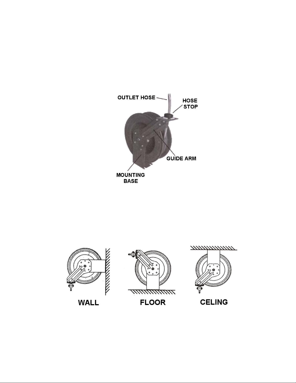
Once you have located a mounting spot, consult the “Typical Mounting Positions” chart below and
choose the diagram that most closely matches your mounting position. If necessary, adjust guide arm
position to match diagram.
Typical Mounting Positions
Page 3

ADJUSTING THE GUIDE ARM
• Pull out 3 feet of ho s e an d a l l o w reel to lock in pos i t i on.
• Remove the four bolts connecting guide arm to mounting base.
• Rotate guide arm in 90° increments to desired position total number of positions is five (5).
• Replace four bolts and tighten.
Continue by choosing proper mounting hardware. See illustration for Dimensions. Use washers on
mounting bolts to help bear weight of reel (Bolts and Washers are not included).
After reel is secured in position, attach air hose coming from compressor . W rap threads of male connector
on incoming air hose with Teflon tape (included) or thread sealant and connect to air inlet valve on side of
hose reel. Connect other end of incoming air hose to air comp ressor . App ly Teflon tape to threads on hose
before attaching air tools.
Page 4

ADJUSTING THE HOSE BALL STOP
The hose bal l stop determine s the length of hose that remai ns outside of reel . To ad just, pull hos e out
past desired position of hose ball stop and latch reel. Loosen both bolts and move ball stop to proper
position. Tighten bolts.
Operating Hose Reel
1. Slowly pull hose from reel to desired length. A ratcheting mechanism inside reel makes a short series
of clicking sounds every half revolution of reel.
2. To lock reel in position, listen for clicking sounds as hose is slowly pulled from reel. When reel clicks,
stop pulling hose. Decrease tension on hose and reel should lock in position.
3. To retract hose onto reel, slowly pull out hose until series of clicking sounds stops (1/8 revolu tion).
DO NOT LET GO OF HOSE!
4. Allow hose to retract slowly until hose ball stop rests against the hose guide.
5. Periodically check the hose for excessive wear and hose connections for air leaks.
ADJUSTING RECOIL TENSION
1. Disconnect incoming air supply.
2. Pull out about 2 feet of hose and latch the reel.
3. Remove hose ball stop
4. While firmly holding onto edge of reel drum, unlatch reel and carefully allow drum to slowly rew ind,
drawing hose end back through guide arm roller assembly and onto reel. Latch reel in position.
5. T o Increase T e nsion: Unlatch reel and turn clockwise (as viewed from air inlet side).
To Decrease Tension: Unlatch and allow reel to rotate slowly counterclockwise (as viewed from air
inlet side).
6. Once desired spring tension is reached, latch reel in position. Feed hose end through roller assembly
in guide arm and reattach hose ball stop.
7. Connect incoming air supply.
Page 5

REPLACING HOSE
1. Secure and stabilize reel. In most cases, hose can be replaced with reel still mounted.
2. Disconnect incoming air supply.
3. Pull out en tire length of hose and lock reel. Make sure reel is securely locked in place.
4. Unscrew hose clamps that secure hose to drum. Disconnect inlet-end of hose from air inlet valve.
5. Pull inlet-end of hose through slot in drum and guide rollers, removing old hose completely.
6. Remove spring hose guard, hose clamp and hose ball stop from old hose. Fit these parts on new
hose in identical positions.
7. Feed inlet-end of hose through guide rollers and slot in drum.
8. Apply Teflon sealant tape or thread sealant to hose connector and connect to air inlet valve.
9. Attach hose clamp to drum. Rewind hose onto reel using normal operation.
Page 6

 Loading...