

ATC GTDHR FIRST, GTDHR INFINITE, GTDHR PREMIUM Operating And Maintenance Instructions Manual
Page 1

GTDHR FIRST / PREMIUM / INFINITE
ENERGY RECOVERY UNIT
OPERATING AND MAINTENANCE INSTRUCTIONS
MS-CDF-001 A Ind A update 01/07/2011 Created by JC Validated by AR 1 / 36
Page 2

SUMMARY
I / RECEIVING THE EQUIPMENT
I.1 / Checks on reception P 4/36
I.2 / Unpacking P 4/36
I.3 / Storing P 4/36
II / INSTALLATION
II.1 / Handling P 4/36
II.2 / Space required P 4/36
II.3 / Installation P 4 and 5/36
II.4 / Siphon P 5/36
III / COMPOSITION AND OPERATION
III.1 / General P 5/36
III.2 / CARMA® EC : 2 fan speeds can be set as % P 6/36
III.3 / CARMA® DIVA® EC : proportional ventilation between two flow-rates
(LS/HS) by CO2 management (ppm) P 6/36
III.4 / CARMA® LOBBY® EC : controlled constant pressure ventilation. (Pa) P 6/36
III.5 / CARMA® MAC2® EC : 1 or 2 CONSTANT flow rates as required . (m3/h) P 6/36
III.6 / CARMA® QUATTRO® EC : Proportional ventilation between 2 CONSTANT
flow rates. (m3/h) by CO2 (ppm) P 6/36
IV / HVAC CONNECTION P 6/36
V / MARKING OF ITEMS IN THE UNIT P 7/36
VI / ELECTRIC WIRING
VI.1 Accessibility of the electric board P 8/36
VI.2 Electric supply and wire section P 8/36
VI.3 Connection of the probes P 8/36
VI.4 Electric board's terminal P 9 to 11/36
VI.4.1 Power terminal connection 9008 to 9070 P 9/36
VI.4.2 Control terminal connection 9008 to 9070 P 10 and 11/36
VI.4.3 Bridging in case of unused option P 11/36
VI.5 Connection of the motors P 12 and 13/36
VI.6 Connection of pressure transmitters for MAC2® EC / LOBBY® EC
/ QUATTRO® EC P 14/36
VI.7 Connection of CO2 transmitter for DIVA® EC / QUATTRO® EC P 14/36
VI.8 Econological bypass P 14/36
VI.9 Night cooling P 15/36
VI.10 Automatic defrost P 15/36
VI.11 Hot water and cold water battery P 15/36
VI.12 Change over battery P 15/36
VI.13 Direct duct expansion battery P 15/36
VI.14 Electric battery associated with a CARMA® FIRST P 16/36
VI.15 Integrated heating electric battery CARMA® PREMIUM BE and INFINITE BE P 16/36
VI.16 Integrated defrosting electric battery CARMA® INFINITE BE and INFINITE BC P 17/36
VI.17 / Repeater P 18/36
GTDHR FIRST / PREMIUM / INFINITE
ENERGY RECOVERY UNIT
MS-CDF-001 A Ind A update 01/07/2011 Created by JC Validated by AR 2 / 36
Page 3

CONTENTS
VII / CONFIGURATION
VII.1 / Control (on Corrigo or remote control) P 18/36
VII.2 / Tree structure of the menus P 19 to 21/36
VII.3 / Modification of the parameters P 22 to 27/36
VII.3.1 Access to the blocked parameters P 22/36
VII.3.2 Setting of various date and time clocks P 22/36
VII.3.2.a Date and time of the CORRIGO regulator P 22/36
VII.3.2.b Programming the system's operating timetable P 22/36
VII.3.2.c Vacation period P 22/36
VII.3.3 Modification of speed / pressure / flow-rate in LS and HS P 23/36
VII.3.3.a CARMA® STANDARD and DIVA® EC P 23/36
VII.3.3.b CARMA® LOBBY® EC P 23/36
VII.3.3.c CARMA® MAC2® and QUATTRO® EC P 23/36
VII.3.4 Temperature set-point modification P 24/36
VII.3.5 CO2 set-point modification P 24/36
VII.3.6 Unit start/stop or forced LS/HS start through the Corrigo or the remote control P 25/36
VII.3.7 Special parameter settings (control type modification and Night Cooling % modification) P 25/36
VII.3.8 Special MODBUS / LON communication and Repeater parameter settings P 26/36
VII.3.8.a Repeaters P 27/36
VII.3.8.b MODBUS Communication P 27/36
VII.3.8.c LON Communication P 27/36
VIII / REPAIR
VIII.1 Various types of faults P 27 to 29/36
VIII.2 Changing the battery P 30/36
IX / MAINTENANCE P 31/36
IX / NOTES AND GRAPHS P 32 to 36/36
GTDHR FIRST / PREMIUM / INFINITE
ENERGY RECOVERY UNIT
MS-CDF-001 A Ind A update 01/07/2011 Created by JC Validated by AR 3 / 36
Page 4

In compliance with the current norms, the machine should be installed only by a technical person qualified for this type
of work. During installation, ensure that:
- The machine is moved as given in chapter II.1.
- The required personal protection devices are worn so as to avoid injuries caused by electrical and mechanical
hazards (injuries by touching panels, sharp edges, etc.)
- Electrical connections are made after the power supply has been shut off, in compliance with the recommendations given in chapter VI.
- Grounding is carried out in compliance with current standards.
- The machine is powered on when installation has finished (ducting installed and inspection doors closed).
I / RECEIVING THE EQUIPMENT
The units are delivered on stringers or palettes then wrapped in plastic film.
I.1 / Checks on reception
When the equipment is received, the state of the packaging and the equipment must be checked. In the event of
damage, make an accurate note of any problems on the carrier's delivery note.
I.2 / Unpacking
When the equipment is unpacked, check the following:
- The total number of packages are present.
- All accessories are present (dampers, roof, electric switchgear, etc.). After unpacking the equipment, the waste must
be disposed of in compliance with the current standards. No packaging should be discarded into the environment.
I.3 / Storing
The equipment must be stored in shade, in a dry place, at a temperature between -20°C and 40°C.
II / INSTALLATION
II.1 / Handling
The units must only be moved in their installation position.
If the device is handled using a fork-lift truck, ensure this supports the load-bearing structure and does not touch
the panels enclosing the unit.
If the device is moved using a crane, use four cables of identical lengths. These must be at least as long as the
greatest distance between two fastening points.
If L + W + H > 5m then the case must be lifted using a lifting beam.
II.2 / Space required
Generally speaking, it is desirable to provide access space of at least the width of the unit on the access side for
maintenance. These units require a siphon and must be installed at a sufficient height to allow this to be installed. Note:
in case of vertical units, provide at least 300mm on the rear for connecting the condensates.
II.3 / Installation
The unit must be laid on a sufficiently rigid and flat surface (use vibration mounts if necessary). For the HVAC
connection, select duct sections based on dimensions of the flexible bands that should be properly stretched.
Install the unit such that bad weather or ambient temperature cannot damage the internal items of the unit during installation as well as when used later (possibly provide a protective cap).
GTDHR FIRST / PREMIUM / INFINITE
ENERGY RECOVERY UNIT
MS-CDF-001 A Ind A update 01/07/2011 Created by JC Validated by AR 4 / 36
Page 5

Installation of the units on the floor: the unit must be laid on a sufficiently rigid and flat surface (use vibration
mounts if necessary). For these units, provide a slope of 2 to 3% for the removal of condensates in the direction of the
width. (Connect the condensates as per chapter II.4).
Outdoor installation of the units:
For raising the unit above the ground (protection from water), a set of feet may optionally be supplied (PCB). A roof
(DCP) as well as grated bevelled nozzles (BBG) or rain cowls (AGC) must also be provided if necessary (available as
options).For these units, provide a slope of 2 to 3% for the removal of condensates in the direction of the width.
(Connect the condensates as per chapter II.4).
Installation of the units on the ceiling: the units must be mounted preferably on a frame suspended from the
structure of the building, taking care to comply with allowable loads (the frame is the installer's responsibility).
For these units, provide a slope of 2 to 3% for the removal of condensates in the direction of the width.
(Connect the condensates as per chapter II.4). Moreover, the CARMA® 9008-9023 units can be suspended directly from
the ceiling by means of M8 threaded rods connected to the attachment lugs on the lower part of the units.
Before starting the unit, check the tightness of all bolts, particularly those of
rotating components
II.4 / Siphon
Provide a siphon on each condensate drainage pipe. A siphon can only be used for one drainage system. Note: the siphon must be connected in accordance with Best Practices in order that the condensates are removed as efficiently as
possible.
The height H must be at least equal to the maximum internal
negative pressure of the unit (p in mm).
Example : p = 500 Pa 50 mm CE
H > 50 mm 2H > 100 mm
III / COMPOSITION AND OPERATION
III.1 / General
The CARMA® range is a programme of double-flow units with high efficiency, high performance self-regulating recovery
of energy meant for office and industrial installations. Its performance is greater than 90%.
CARMA® FIRST: allows managing a non-integrated changeover battery or (a non-integrated hot water battery and/or a
non-integrated cold water battery) or a non-integrated electric battery.
If required, it can also manage a non-integrated electric battery and a non-integrated cold water battery
CARMA® PREMIUM BC: Manages an integrated hot water battery and also allows managing an additional nonintegrated cold water battery.
CARMA® PREMIUM BE: Manages an integrated electric battery and also allows managing an additional non-integrated
cold water battery.
CARMA® INFINITE BC: manages an integrated hot water battery, an integrated defrost battery and also allows managing an additional non-integrated cold water battery.
CARMA® INFINITE BE: manages an integrated electric battery, an integrated defrost battery and also allows managing
an additional non-integrated cold water battery.
GTDHR FIRST / PREMIUM / INFINITE
ENERGY RECOVERY UNIT
MS-CDF-001 A Ind A update 01/07/2011 Created by JC Validated by AR 5 / 36
PCB
dpc
BBG
AGC
Page 6

GTDHR FIRST / PREMIUM / INFINITE
ENERGY RECOVERY UNIT
MS-CDF-001 A Ind A update 01/07/2011 Created by JC Validated by AR 6 / 36
III.2 / CARMA® : 2 adjustable fan speeds
Adjustment of a minimum speed (L.S.) and a maximum speed (H.S.) in %.
Fitted with a factory tuned clock under permanent HS operation (in LS from 10 p.m.
to 6 a.m. for authorisation of the Night Cooling operation).
Possibility of adding a remote forced stop (dry NO contact )
Possibility of adding a LS/HS remote forced operation (dry NO contacts )
Supply air temperature management with outdoor compensation (air relationship).
III.3 / CARMA® DIVA® EC : proportional ventilation between two flow rates (LS/HS) by CO2
management
Adjustment of a minimum speed (L.S.) and a maximum speed (H.S.) in %.
The CO2 set-point is factory-set at 1000ppm (compliant with RT2012).
The variation between LS and HS will depend on the CO2 level
Fitted with a factory tuned clock under permanent LS operation.
Possibility of adding a LS/HS remote forced operation (dry contacts NO)
Possibility of adding a remote forced stop (dry contact NO)
Supply air temperature management with outdoor compensation (air relationship).
Note: In order for the CO2 regulation to work, the installation must strictly follow the following constraints:
HS Clock at 0 (Normal speed timer)
LS Clock in operation (Reduced speed timer)
No triggering of any forced operation (LS/HS) or forced stop.
III.4 / CARMA® LOBBY® EC : constant pressure ventilation. (Pa)
Constant pressure adjustment (Pa).
Fitted with a factory tuned clock under permanent LS operation.
Possibility of adding a LS remote forced operation (dry contact NO)
Possibility of adding a remote forced stop (dry contact NO)
Supply air temperature management with outdoor compensation (air relationship).
III.5 / CARMA® MAC2® EC : 1 or 2 CONSTANT flow rates as required. (m3/h)
Adjustment of 1 or 2 constant flow rates (LS/HS) (m3/h).
Fitted with a factory tuned clock under permanent HS operation (in LS from 10 p.m.
to 6 a.m. for authorisation of the Night Cooling operation).
Possibility of adding a LS/HS remote forced operation (dry contact NO)
Possibility of adding a remote forced stop (dry contact NO)
Supply air temperature management with outdoor compensation (air relationship).
III.6 / CARMA® QUATTRO® EC: Proportional ventilation between 2 CONSTANT flow rates (m3/h) by CO²
Adjustment of a minimum flow-rate (L.S.) and a maximum flow-rate (H.S.) in m3/h.
The CO2 set-point is factory-set at 1000ppm (compliant with RT2012).
The variation between LS and HS will depend on the CO2 level
Fitted with a factory tuned clock under permanent LS operation.
Possibility of adding a LS/HS remote forced operation (dry contacts NO)
Possibility of adding a remote forced stop (dry contact NO)
Supply air temperature management with outdoor compensation (air relationship).
Note: In order for the CO2 regulation to work, the installation must strictly follow the following constraints:
HS Clock at 0 (Normal speed timer)
LS Clock in operation (Reduced speed timer)
No triggering of any forced operation (LS/HS) or forced stop.
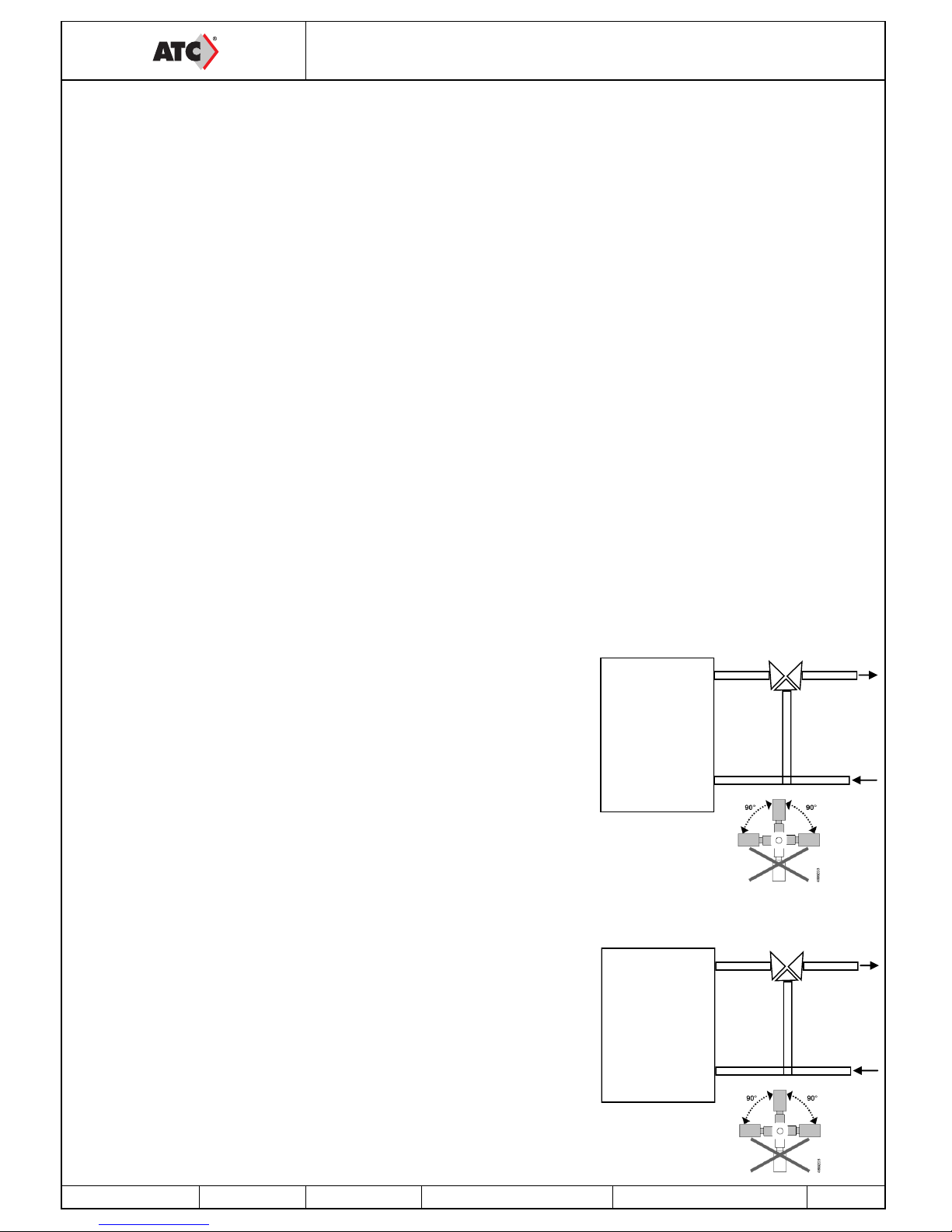
IV / HVAC CONNECTION
Connect the unit with the help of labels placed on each tapping. The network should clearly be heat insulated.
This should be done using Best Practices (no elbow on fan outlet before a minimum distance of 5 times the tapping diameter,
etc.).
HS Speed
LS Speed
HS Speed
LS Speed
Flow-rate
Constant pressure
Constant flow-rate HS
Constant flow-rate LS
Constant flow-rate HS
Constant flow-rate LS
Flow-rate
Constant flow-rate LS
Flow-rate
Flow-rate
Page 7

V / MARKING OF ITEMS IN THE UNIT
GTDHR FIRST / PREMIUM / INFINITE
ENERGY RECOVERY UNIT
MS-CDF-001 A Ind A update 01/07/2011 Created by JC Validated by AR 7 / 36
NEW AIR RETURN AIR
VS = Supply Air Fan VR = Return Air Fan
DEP FS = Filter Pressure Switch (only for new
air)
PT1000 PROBES and Servomotors
SSG = Supply Air Duct Probe SDG = Duct Defrost Probe
SEG = External Duct Probe SBD = Defrost Probe Battery
SRG = Return Air Duct Probe
SM1 and SM2 = 100% Bypass Servomotor
VS
VR
DBE
DEP FS
SRG
SSG
SEG
SDG
SBD
SM
Page 8

VI / ELECTRIC WIRING
VI.1 Accessibility of the electric board
The electric board is always placed in the return-air flow. The access panel is held with the help of one or two ¼-turn
locks (CARMA® 9008-9048) or by bolts (CARMA® 9070).
VI.2 Electric supply and wire section
The CARMA® units are connected with either 230 V SINGLE PHASE or with 400V THREE PHASE + NEUTRAL (see
intensity table below for power supply cable selection). The power supply is directly connected to the local circuit
breaker (the labels shall help you to know where to connect the neutral on the circuit breaker). The earth wire is directly
connected to the insert located on the door or on the band of the EASY module.
VI.3 Connection of the probes
All the items are factory connected on the terminal except the temperature probes that are connected directly to the
CORRIGO regulator.
SSG: Supply Air Duct Probe on Agnd(30) and AI1(31)
SEG: External Duct Probe on Agnd(30) and AI2(32)
SDG: Duct Defrost Probe on Agnd(33) and AI3(34)
SRG: Return Air Duct Probe on Agnd(33) and AI4(35)
SBD: Defrost Battery Probe on Agnd(36) and AI4(37) for INFINITE BE or a 1000 Ohms resistance for FIRST and PRE-
MIUM
GTDHR FIRST / PREMIUM / INFINITE
ENERGY RECOVERY UNIT
MS-CDF-001 A Ind A update 01/07/2011 Created by JC Validated by AR 8 / 36
TYPE OF UNIT FIRST ET PREMIUM
BC
PREMIUM BE INFINITE BC INFINITE BE
9008 3.4 A (230V MONO) 14.3 A (230V MONO)
9008 025 14.3 A (230V MONO) 25.2 A (230V MONO)
9010 6.2 A (230V MONO) 22.5 A (230V MONO)
9010 037 17.1 A (230V MONO) 33.4 A (230V MONO)
9016 7.8 A (230V MONO) 15.4 A (400V TRI + N)
9016 037 24.1 A (230V MONO)
9016 052 15.4 A (400V TRI + N) 23 A (400V TRI + N)
9023 7.8 A (230V MONO) 17.5 A (400V TRI + N)
9023 037 24.1 A (230V MONO)
9023 067 17.5 A (400V TRI + N) 27.2 A (400V TRI + N)
9035 8 A (400V TRI + N) 19.9 A (400V TRI + N)
9035 067 17.7 A (400V TRI + N) 29.6 A (400V TRI + N)
9035 135 27.5 A (400V TRI + N) 39.4 A (400V TRI + N)
9048 8 A (400V TRI + N) 34 A (400V TRI + N)
9048 067 17.7 A (400V TRI + N) 43.7 A (400V TRI + N)
9048 135 27.5 A (400V TRI + N) 53.5 A (400V TRI + N)
9070 8.4 A (400V TRI + N) 44.1 A (400V TRI + N)
9070 105 23.6 A (400V TRI + N) 59.3 A (400V TRI + N)
9070 157 31.1 A (400V TRI + N) 66.9 A (400V TRI + N)
The unit may malfunction due to wrong choice of wire section. The wire section must be selected
according to NF C15-100
Page 9

VI.4 Electric board's terminal
VI.4.1 Power terminal connection 9008 to 9070
GTDHR FIRST / PREMIUM / INFINITE
ENERGY RECOVERY UNIT
MS-CDF-001 A Ind A update 01/07/2011 Created by JC Validated by AR 9 / 36
35
38
29
39
30
40 41
32
42 43
34
44 45
36 31 33
Power terminal and accessories
for fan operations
(on upper DIN rail)
7
15
1
16
2
17 18 4 19 20 6 21 22
8 3 5
243
9
24
10
25 26
12
27 28
14 11 13
Control terminal
(on lower DIN rail)
46
37
35
38
29
39
30
40 41
32
42 43
34
44 45
36 31 33
Power terminal and accessories
for fan operations
(on upper DIN rail)
46
37
Name Termi-
nals
Connection
DEP S 29
30
To be connected on terminals 1 and 3 of the air
flow-rate control DEPressure Switch on Supply Air
fan set at 30Pa (to be noted that safety of the airflow rate shall be managed by the pressure transmitter in case of the LOBBY® EC, QUATTRO® EC,
MAC2® EC option. In this case do not connect anything to these terminals).
SUPPLY AND
RETURN AIR
MOTOR
31-3233-3435-3640-41
According to De CARMA® size (see chapter VI.5)
DEP S 38
39
To be connected on terminals 1 and 3 of the air
flow-rate control DEPressure Switch on Return Air
fan set at 30Pa (to be noted that safety of the airflow rate shall be managed by the pressure transmitter in case of the LOBBY® EC, QUATTRO® EC,
MAC2® EC option. In this case do not connect anything to these terminals).
BE Regulator
(PREMIUM AND
INFINITE BE
only)
42
43
Only for CARMA® PREMIUM BE and INFINITE
BE, connect on terminals 1 and 2 of the BE regula-
tor. (see chapter VI.15)
DEP FS 44
45
To be connected on terminals 1 and 3 of the fouling
DEPressure switch of the Supply Air Filter. (set at
200Pa)
THS (PREMIUM
AND INFINITE
BE only)
37
46
Only for CARMA® PREMIUM BE and INFINITE
BE, connect on terminals C and 2 of the electric
battery's Safety Thermostat. (see chapter VI.15)
Page 10

VI.4.2 Control terminal connection 9008 to 9070
* direct connection on CORRIGO
GTDHR FIRST / PREMIUM / INFINITE
ENERGY RECOVERY UNIT
MS-CDF-001 A Ind A update 01/07/2011 Created by JC Validated by AR 10 / 36
7
15
1
16
2
17 18 4 19 20 6 21 22
8 3 5
243
9
24
10
25 26
12
27 28
14 11 13
Control terminal
(on lower DIN rail)
Name Termi-
nals
Connection
RMS 1
DO3*
To be connected on terminals 1 and 2 of the Motorised Supply Air Damper (GMA
121.1E)
RMR 2
DO4*
To be connected on terminals 1 and 2 of the Motorised Return Air Damper (GMA
121.1E)
AL 3
DO5*
To be connected on the terminals of a remote alarm indicator (2A 24VAC MAX)
DBE (INFINITE
only)
4
DO6*
To be connected on the terminals of the defrost battery's static switch (Detachable)
(see chapter VI.16)
NC (Night cooling)
(LOBBY® EC)
2
DO7*
24V output available if the CARMA® unit is associated with the LOBBY EC option for
opening the dampers during Night Cooling period. (see chapter VI.9)
DX 2
DO7*
24V output available for starting a direct expansion module (should be specified in
the order) (see chapter VI.13)
ADP 5
6
To be connected on the NF contact of the Remote Firefighter's Stop button. As its
name states, this contact should be used only in a firefighter's stop function since it
directly stops the system and shunts all the safeties.
REPEATER 7
8
B-A-N*
To be connected on the repeater if you would like to shift the remote control more
than 10m away. (see chapter VI.17)
MF HS 9-10 To be connected to the terminals of a NO contact provided for the High Speed
Forced Operation
MF LS 11-12 To be connected to the terminals of a NO contact provided for the Low Speed Forced
Operation
AR EXT 13-14 To be connected to the terminals of a NO contact provided for the Forced External
Stop (Note: if contact closed, unit is at stop)
Page 11

* direct connection on CORRIGO
VI.4.3 Bridging in case of unused option.
GTDHR FIRST / PREMIUM / INFINITE
ENERGY RECOVERY UNIT
MS-CDF-001 A Ind A update 01/07/2011 Created by JC Validated by AR 11 / 36
Name Termi-
nals
Connection
TRPS (LOBBY® EC
and MAC2® EC and
QUATTRO® EC)
15
Agnd*
UI2*
Supply Air Pressure Transmitter (see chapter VI.6)
TRPS (LOBBY® EC
and MAC2® EC and
QUATTRO® EC)
16
Agnd*
UI3*
Return Air Pressure Transmitter (see chapter VI.6)
CO2 (DIVA® EC and
QUATRO® EC)
17
Agnd*
UI4*
CO2 Transmitter (see chapter VI.7)
THS/THA
Or
K1 auxiliary for
PREMIUM and INFINITE BE only
18
19
BC: In PREMIUM BC and INFINITE BC versions, the THA is factory connected.
FIRST versions, if you install an additional BC module to the CARMA® unit, to
be connected to the C and 2 terminals of the Anti-frost thermostat.
BE: PREMIUM BE and INFINITE BE versions, the K1 auxiliary contact is factory
connected.
FIRST version, if you install an additional BE module to the CARMA® unit, to
be connected to the C and 2 terminals of the battery's Safety Thermostat.
BC/BE 20
21
22
BC: To be connected on the three-way valve of the Hot Water Battery (see chapter
VI.11)
BE not integrated (FIRST): (see chapter VI.14)
BE integrated (PREMIUM BE INFINITE BE): (see chapter VI.15)
BIM 23
24
25
To be connected on the Motorised Bypass servomotor (see chapter VI.8)
BF 26
27
28
To be connected on the three-way valve of the Cold Water Battery (see chapter
VI.11)
7
15
1
16
2
17 18 4 19 20 6 21 22
8 3 5
243
9
24
10
25 26
12
27 28
14 11 13
Name Termi-
nals
Connection
ADP 5-6 If you do not use the Remote Fire-
fighter Stop function, the terminals
5 and 6 should be bridged. This is
done in factory.
THS/THA 18-19 For CARMA® FIRST only, the ter-
minals 18-19 should be bridged if
you are not adding battery in duct.
This is done in factory
Page 12

VI.5 Connection of the motors
The motors are factory connected.
GTDHR FIRST / PREMIUM / INFINITE
ENERGY RECOVERY UNIT
MS-CDF-001 A Ind A update 01/07/2011 Created by JC Validated by AR 12 / 36
CARMA 9008®
SUPPLY AIR
POWER CONTROL
CONTROL
GREEN/YELLOW
BLUE
BROWN
BLUE
YELLOW
GREEN/YELLOW
BLUE
BROWN
WHITE
BROWN
SHIELDING
GREEN/YELLOW
BROWN
BLUE
BLUE
YELLOW
SHIELD
POWER
RETURN AIR
CARMA 9010®
RETURN AIR
CONTROL
POWER CONTROL
SUPPLY AIR
POWER
Page 13

GTDHR FIRST / PREMIUM / INFINITE
ENERGY RECOVERY UNIT
MS-CDF-001 A
Ind A update 01/07/2011 Created by JC Validated by AR
13 / 36
GTDHR 9016-9023
CONTROL POWER
SUPPLY AIR
POWER CONTROL
RETURN AIR
RETURN AIR
GTDHR 9035-9048 GTDHR 9070
RETURN AIR
Page 14

VI.6 Connection of pressure transmitters for MAC2® EC / LOBBY® EC / QUATTRO® EC
The pressure transmitters are factory wired.
VI.7 Connection of CO2 transmitter for DIVA® EC / QUATTRO® EC
The CO2 transmitter is factory wired.
VI.8 Econological bypass
This function is automatically controlled using the CORRIGO regulator's programming and the probes installed as standard in our double-flow CARMA® units.
In winter: When heat is required, the Bypass closes to recover maximum calories through the plate exchanger. If this
recovery is not adequate to reach the temperature set-point, the water battery valve will open or the electric battery will
start.
In summer (FREE COOLING): The Bypass closes when the outside temperature is higher than the inside temperature
to prevent the outside heat from entering directly. If the outside temperature is lower than the inside temperature, the
Bypass opens to get the cool outside air.
For the CARMA 9048-9070, the single servomotor is wired in the same manner as the small shutter.
GTDHR FIRST / PREMIUM / INFINITE
ENERGY RECOVERY UNIT
MS-CDF-001 A
Ind A update 01/07/2011 Created by JC Validated by AR
14 / 36
CARMA LOBBY / MAC2 AND QUATTRO EC
PRESSURE TRANSMITTER
CARMA Terminal
Bypass Servomotor recuperator
side
SMALL SHUTTER
Bypass Servomotor recuperator
front
LARGE SHUTTER
Page 15
VI.9 Night cooling
This function is used during summer to cool the buildings at night by using cool outdoor air. Thus the cooling power to
be delivered during the day is reduced. The Night Cooling function works only between midnight and morning 7 a.m.
During a Night Cooling period, the heating and cooling outlets are blocked. The Bypass is also open to prevent air from
travelling through the exchanger. At the end of a Night Cooling period, the heating is blocked for 60 minutes.
Operating Conditions:
The outdoor temperature was greater than 22°C during the day
The clocks are set either in LS or at stop between midnight and 7 a.m.
The outdoor temperature is less than 18°C during the Night Cooling period
The outdoor temperature is greater than 10°C during the Night Cooling period
The room's ambient temperature is greater than 18°C
During the Night Cooling period, the fan runs at 85% capacity. This speed can be adjusted. See chapter VII.3.7
For the LOBBY® EC version, a maximum 24V 2A output is provided to you between the DO7 and 2 terminals to force
the opening of the dampers during the Night Cooling period.
VI.10 Automatic defrost
This function is automatically controlled using the CORRIGO regulator's programming and the probes installed as standard in our double-flow CARMA® units. Defrosting starts with the opening of the Bypass (defrost temperature (SDG) less
than 5°C). If the Bypass function is not adequate to defrost the exchanger (of the outside temperature is less than -10°
C), the new air fan modulates its flow-rate until stop and then restarts as soon as the defrost temperature probe becomes greater than 5°C.
For the INFINITE version: a defrost battery is installed on the new air. This regulates the exchanger's incoming temperature at –5°C. This shall eliminate any risk of frost while keeping the Bypass as closed as possible. Thus, maximum
efficiency of the system is maintained
VI.11 Hot water and cold water battery (the valve should be connected in off position)
In PREMIUM BC and INFINITE BC version, the hot water battery is already installed in the unit. The Anti-frost Thermostat is connected. However, you should wire the 3-way valve.
For all other versions, also connect the THA (Anti-frost Thermostat) and shift the supply air probe after the battery
Connect the 3-way valve's servomotor as follows:
Hot battery:
Terminal 20 of the CARMA® unit to the +24V (G) of the valve's servomotor
Terminal 21 of the CARMA® unit to the 0V (G0) of the valve's servomotor
Terminal 22 of the CARMA® unit to the 10V (Y) of the valve's servomotor
Connect the NF contact (C and 2) of the THA (Anti-frost Thermostat) to 18 and 19
Cold battery:
Terminal 26 of the CARMA® unit to the +24V (G) of the valve's servomotor
Terminal 27 of the CARMA® unit to the 0V (G0) of the valve's servomotor
Terminal 28 of the CARMA® unit to the 10V (Y) of the valve's servomotor
Connect the NF contact (C and 2) of the THA (Anti-frost Thermostat) to 18 and 19
VI.12 Changeover battery (only in FIRST version) (the valve should be connected in off position)
A changeover battery can be installed in FIRST version. In this case you will not be able to add another battery (hot water or cold water battery). You should connect the 3-way valve, the changeover handle, the THA (Anti-frost Thermostat)
and shift the supply air probe after the battery
Connect the assembly as follows:
Red wire of the handle (CO) on Y of the valve's servomotor
Terminal 20 of the CARMA® unit to the +24V (G) of the valve's servomotor
Terminal 21 of the CARMA® unit to the 0V (G0) of the valve's servomotor
Terminal 22 of the CARMA® unit to the brown wire of the handle at the hot signal
Terminal 28 of the CARMA® unit to the black wire of the handle at the cold signal
Connect the NF contact (C and 2) of the THA (Anti-frost Thermostat) to 18 and 19
VI.13 Direct expansion battery (this function should be mentioned on ordering)
A maximum 24V 2A output is provided to control the start stop of your cold unit to
be connected between terminals DO7 and 2 (provide a relay on the condensation unit).
You should also shift the supply air probe after the direct expansion battery.
GTDHR FIRST / PREMIUM / INFINITE
ENERGY RECOVERY UNIT
MS-CDF-001 A
Ind A update 01/07/2011 Created by JC Validated by AR
15 / 36
BATTERY
A
AB
B
BATTERY
A
AB
B
Page 16

VI.14 Electric battery associated with a CARMA® FIRST (should be specified with the order)
Possibility of adding an electric battery in duct at the CARMA® FIRST unit. In this case we provide you with a heating signal 0-10V (terminal 21-22) as well as the terminals 18-19 to bring your safety thermostat's NF contact (break contact by temperature rise). If the CARMA® unit is linked to an electric battery provided with a CAB-CBE (electric battery
housing), follow the diagram as given below.
VI.15 Heating electric battery CARMA® PREMIUM BE and INFINITE BE
In PREMIUM BE and INFINITE BE version, the electric battery is already installed in the unit. The safety Thermostat
and the 0-10V control are connected.
GTDHR FIRST / PREMIUM / INFINITE
ENERGY RECOVERY UNIT
MS-CDF-001 A
Ind A update 01/07/2011 Created by JC Validated by AR
16 / 36
Ph1
Ph2
Ph3
L1
L2
L3
24g
N
24v
TH
TH
AL
AL
0V 10V
400V 3-Phase
Power Supply
To Electric
Battery
7
8
18 19
21
22
CAB-CBE Terminal
CARMA® Terminal
BE Regulator
BE Regulator
Single phase heating battery
Three phase heating battery
Page 17

VI.16 Defrosting electric battery CARMA® INFINITE BE and INFINITE BC
In INFINITE BE and INFINITE BC version, the defrost battery is already installed in the unit. The control is also
connected.
GTDHR FIRST / PREMIUM / INFINITE
ENERGY RECOVERY UNIT
MS-CDF-001 A
Ind A update 01/07/2011 Created by JC Validated by AR
17 / 36
Single phase defrost battery
Three phase defrost battery
Page 18

VI.17 / Repeater (see chapter VII.3.8 for the configuration)
If you would like to have remote control in addition to the display, you must use a repeater. In this case you can move
the remote control system up to 1 km away. Use a shielded twisted 2-pair cable of BELDEN 8723 type or equivalent to
connect the repeater to the control housing and a standard cable (2x0.5 min. to 2x1.5 max.) for the 24V. You can connect up to 6 housings to the same repeater. Cannot be linked to a MODBUS communication but can be linked to a LON
communication.
VII / SETTING
VII.1 / Control (on Corrigo or remote control)
The monitor has four rows with 20 characters. It is back-lit. This lighting is not permanent but activates when a key is
pressed. The lighting switches off after a period of inactivity.
There are two LEDs on the front panel:
Alarm LED represented by the bell symbol.
Write LED represented by the pencil symbol.
Rapid blinking = possibility of changing the value
Slow blinking = a password needs to be entered to change the value
The Up, Down, Left and Right directional keys are used to navigate inside the menus.
The Up and Down keys are also used to increase or decrease the value of a parameter when it is accessible
whereas the Left and Right keys are also used to navigate within the same parameter.
The OK key is used to enter the value and confirm a selection and the C key is used to cancel.
The alarm key (red) is used to access the fault list.
The left arrow is also used to exit the alarm menu to return to the main menu
The cursors show you the possible movements and on which arrows to press.
GTDHR FIRST / PREMIUM / INFINITE
ENERGY RECOVERY UNIT
MS-CDF-001 A
Ind A update 01/07/2011 Created by JC Validated by AR
18 / 36
CORRIGO CARMA
REPEATER
7 8
Connect the wires as follows:
B of the repeater to the B terminal of the CARMA® unit (wire of the shielded cable as given in the diagram below)
A of the repeater to the A terminal of the CARMA® unit (wire of the shielded cable as given in the diagram below)
N of the repeater to the N terminal of the CARMA® unit (shielding of the shielded cable as given in the diagram
below)
G of the repeater to terminal 7 of the CARMA® unit
G0 of the repeater to terminal 8 of the CARMA® unit
Arrows
(MENU
directional
keys)
Cursor
Analogue input:
Digital input:
Analogue output:
Digital output:
Option of going up
Option of going down
Less than 1000m
10m (cable supplied)
Page 19

GTDHR FIRST / PREMIUM / INFINITE
ENERGY RECOVERY UNIT
MS-CDF-001 A
Ind A update 01/07/2011 Created by JC Validated by AR
19 / 36
Words written normally = view only / Words in bold = Modification possible / Words in bold underlined =
Modification possible with password 3333. = not used or not accessible.
NOTE: Do not change parameters other than those shown in bold, else no After Sales Service can be incl uded
Running mode
CARMA (+ option)
Year:month:day Time
System:Start oper. or stop
SP: T°C Set point Act: T°C current
Corrigo E
Ventilation
Made By
CALADAIR
Ventilation
Version :
Id number :
Running mode
…
Operating mode
Auto (7)
Operating
period
Vent.AS: 00.0 Hours
Viewing the
alarm log
(use the bottom arrow
to scroll the log)
Alarm report
Inputs/outputs
Analogue inputs AI1: AS Temp (supply air)
AI2: Ext Temp (outdoor)
AI3: Def Temp (defrost)
AI4: AR Temp (return air)
Digital inputs
DI1: Mar Ind.Fonc AS
DI2: Mar Ind.Fonc AR
DI3: Filter alarm
DI4: Overheat
DI5: Forced Start 1/1
DI6: Forced Start 1/2
DI7: External stop
Analogue outputs
AO1: Heating
AO2: Exchanger
AO3: Cooling
AO4: AS Vfr
AO5: AR Vfr
Digital outputs
DO1: AS Vfr Start
DO2: AR Vfr Start
DO3: AS damper
DO4: AR damper
DO5: Alarm Total
DO6: Defrost start(INFINITE)
VII.2 / Tree structure of the menus
Operating
period
Vent.AR: 00.0 Hours
Universal input UAI1: Sup Loop Temp
(exchanger input (INFINITE))
UAI2: AS Press
(LOBBY / MAC2 & QUATTRO)
UAI3: AR Press
(LOBBY / MAC2 & QUATTRO
UAI4: CO2 (DIVA / QUATTRO)
Page 20

GTDHR FIRST / PREMIUM / INFINITE
ENERGY RECOVERY UNIT
MS-CDF-001 A
Ind A update 01/07/2011 Created by JC Validated by AR
20 / 36
Temperature regulation
Ext. temp:
Supply air temp.
Actual: Set-point
Set-point :
Outdoor comp. set-point
-20°C = 25°C (8)
-15°C = 24°C (8)
-10°C = 23°C (8)
Outdoor comp. set-point
-5°C = 23°C (8)
0°C = 22°C (8)
5°C = 20°C (8)
Outdoor comp. set-point
10°C = 18°C (8)
15°C = 18°C (8)
Return air temperature
Actual:
...
Air control
Frequency control
(CARMA® STANDARD OR DIVA® EC)
AS manual vent.
Output: 75 (5) %
or
VAS pressure control
(CARMA® LOBBY® EC)
Actual: 183Pa (example)
Set-point: 180Pa (5)
or
VAS flow-rate control
(CARMA® MAC2® OR QUATTRO® EC)
Actual: 4178m3/h (example)
Set-point: 5000m3/h (5)
Frequency control
AS manual vent.
Output 1/1: 75% (5)
Output 1/2: 50% (5)
...
CO2 (CARMA
®
DIVA® EC OR QUATTRO® EC)
Actual : 654ppm (example)
Set-point: 1000ppm (6)
VAS pressure control
Set-point 1/1: not used
Set-point 1/2: 180Pa (5)
...
VAS flow-rate control
Set-point 1/1: 5000m3/h (5)
Set-point 1/2: 2500m3/h (5)
...
Frequency control
(CARMA® STANDARD OR DIVA® EC)
AR manual vent.
Output: 75 (5) %
or
VAR pressure control
(CARMA® LOBBY® EC)
Actual: 183Pa (example)
Set-point: 180Pa (5)
or
VAR flow-rate control
(CARMA® MAC2® OR QUATTRO® EC)
Actual: 4178m3/h (example)
Set-point: 5000m3/h (5)
Frequency control
AR manual vent.
Output 1/1: 75% (5)
Output 1/2: 50% (5)
...
VAR pressure control
Set-point 1/1: not used
Set-point 1/2: 180Pa (5)
...
VAR flow-rate control
Set-point 1/1: 5000m3/h (5)
Set-point 1/2: 2500m3/h (5)
...
Page 21

GTDHR FIRST / PREMIUM / INFINITE
ENERGY RECOVERY UNIT
MS-CDF-001 A
Ind A update 01/07/2011 Created by JC Validated by AR
21 / 36
Normal speed schedule Normal speed
Monday (2)
Per 1 : 07:00 - 12:00
Per 2 : 14:00 - 18:00
Normal speed
Monday Friday (2)
Per 1: 07:00 - 12:00
Per 2: 14:00 - 18:00
Normal speed
Tuesday (2)
Per 1 : 07:00 - 12:00
Per 2 : 14:00 - 18:00
Etc… up to Sunday + vacations
Time setting
Time/Date
Time: 15:54 (1)
Date : 2011-01-25 (1)
Day: Tuesday (1)
Reduced speed schedule Reduced speed
Monday (3)
Per 1 : 12:00 - 14:00
Per 2 : 18:00 - 00:00
Reduced speed
Monday Friday (3)
Per 1 : 12:00 - 14:00
Per 2 : 18:00 - 00:00
Reduced speed
Tuesday (3)
Per 1 : 12:00 - 14:00
Per 2 : 18:00 - 00:00
Etc… up to Sunday and vacations
Vacations (mm:dd) up to 24 periods (4)
1: 01-01 - 01:01 (example 1 January)
2: 12-25 - 12:25 (example 25 December)
(1) Time/Date/Day Setting (see chapter VII.3.2.a)
(2) High Speed periods setting (see chapter VII.3.2.b)
(3) Low Speed periods setting (see chapter VII.3.2.b)
(4) Vacation dates setting (see chapter VII.3.2.c)
(5) Setting of speeds, pressures, flow-rates (see chapter VII.3.3)
(6) CO2 level setting (see chapter VII.3.5)
(7) The unit's On/Off operation setting (see chapter VII.3.6)
(8) Temperature set-point setting (see chapter VII.3.4)
Vacations
The forced start menu
should not be used. All the
values should be at 0.
Access right
Enter
Exit
…
Enter password
Of the author. level
Desired: ****
Actual lev.:
Exit this level
of authorisation? NO or YES
Actual lev.:
Page 22

GTDHR FIRST / PREMIUM / INFINITE
ENERGY RECOVERY UNIT
MS-CDF-001 A
Ind A update 01/07/2011 Created by JC Validated by AR
22 / 36
VII.3 / Modification of the parameters
VII.3.1 Access to the blocked parameters
Some parameters are blocked by a password, in this case, when you would like to modify them by pressing the OK key,
this screen will appear.
Enter the code 3333 with the help of the directional keys and then validate with the OK key. Press twice on left arrow to
access the menus. In case of an operating error, press twice on the C key and restart the operation
VII.3.2 Setting of various date and time clocks (password required)
VII.3.2.a Date and time of the CORRIGO regulator (1) chapter VII.2
Date and time of the regulator are configured by default in the CORRIGO. Change to the Summer/Winter time is managed automatically. If you are required to modify this data, follow the procedure given below:
Move the cursor to the Time/Date menu as given in chapter VII.2.
Once on this menu: press the OK key
Enter the desired value.
Validate by pressing the OK key to go to the next field.
Once all the values are updated, press on the left arrow to return to the welcome screen.
VII.3.2.b Programming the system's operating timetable (2) (3) chapter VII.2
The system is set to work at normal speed from 6 a.m. to 10 p.m. and at reduced speed from 10 p.m. to 6 a.m. except
CARMA® DIVA® EC / LOBBY® EC and QUATTRO® EC which is set at permanent reduced speed (Night cooling active
function). If you would like to modify the operating hours (stop between midday and 2 pm., etc. ), follow the procedure
given below:
Move the cursor to the Normal speed pgr or Reduced speed pgr menu as indicated in chapter VII.2.
Once on this menu: press the OK key
Fill-in the desired value.
Validate by pressing the OK key to go to the next field.
Use the down arrow to go to the next day. (note: you will be able to set 2 periods each day for each day of the
week and allow 2 periods for the vacation days).
As indicated on the table, you can also modify the periods from Monday to Friday by pressing on the right key
when you are on the screen for Monday see chapter VII.2.
Once all the values are updated, press on the left arrow to return to the welcome screen.
Note: if reduced speed (LS) and normal speed (HS) are active in the same time slot, the unit will operate at HS
Operating exceptions:
DIVA® EC and QUATTRO® EC: In order for the CO2 control to work, no normal speed time
slot should be active.
LOBBY EC®: Only the reduced speed clock is active
VII.3.2.c Vacation period (4) chapter VII.2
The system is set with no vacation period. If you would like to reduce the operating time during the vacation periods, set
the vacation operating times as given in chapter VII.3.2.b), then set your vacation days.
Follow the procedure given below:
Move the cursor to the Vacation menu as given in chapter VII.2.
Once on this menu: press the OK key
Enter the desired value.
Validate by pressing the OK key to go to the next field.
Use the down cursor to go to the subsequent periods. (note: you can set up to 24 vacation periods).
Once all the values are updated, press on the left arrow to return to the welcome screen.
Normal speed or Reduced speed
Monday
Per1: e.g.: 07:00 - 12:15
Per2: e.g.: 14:00 - 18:00
Enter password of the authorisation level
Password: ****
Level: Without
Time: e.g.: 10:33
Date: e.g.: 08/12/23 (year/month/day)
Day: e.g.: Tuesday
Vacations (month/day)
1 : e.g.: 12:20 - 12:27 (from 20 to 27 Dec.)
2 : e.g.: 01:05 - 01:05 (1st May)
Page 23

GTDHR FIRST / PREMIUM / INFINITE
ENERGY RECOVERY UNIT
MS-CDF-001 A
Ind A update 01/07/2011 Created by JC Validated by AR
23 / 36
VII.3.3 Modification of speed / pressure / flow-rate in LS and HS (password required)
VII.3.3.a CARMA® STANDARD and DIVA® EC (5) chapter VII.2
You can change the rotation speeds of your unit to LS (reduced speed) and HS (normal speed) for each fan in order to
set your flow-rates. To set your initial HS flow-rate, force the system into normal speed with the available "Forced HS"
terminals (bridge between terminals 9 and 10). To set your initial LS flow-rate, force the system into reduced speed with
the available "Forced LS" terminals (bridge between terminals 11 and 12).
Move the cursor to the AS or AR manual vent. frequency control menu as given in chapter VII.2.
Once on this menu: press the OK key (1/1 = GV)
(1/2 = PV)
Enter the desired value using the graphs in appendices at the end of the instructions.
Validate by pressing the OK key to go to the next field.
Once all the values are updated, press on the left arrow to return to the welcome screen.
VII.3.3.b CARMA® LOBBY® EC (5) chapter VII.2
You can change the constant pressure of your unit for each fan to set your flow-rates. To set your initial HS flow-rate,
force the system into normal speed with the available "Forced LS" terminals (bridge between terminals 11 and 12).
Move the cursor to the VAS pressure control menu as given in chapter VII.2.
Once on this menu: press the OK key
Enter the desired value.
Validate by pressing the OK key to go to the next field.
Once all the values are updated, press on the left arrow to return to the welcome screen.
VII.3.3.c CARMA® MAC2® and QUATTRO® EC (5) chapter VII.2
You can change the constant speeds of your unit to LS (reduced speed) and HS (normal speed) for each fan.
Move the cursor to the VAS flow-rate control menu as given in chapter VII.2.
Once on this menu: press the OK key (1/1 = GV)
(1/2 = PV)
Enter the desired value.
Validate by pressing the OK key to go to the next field.
Once all the values are updated, press on the left arrow to return to the welcome screen.
Frequency control
AS or AR manual vent.
Output 1/1: 75%
Output 1/2: 50%
...
VAS or VAR pressure control
Set-point 1/1: not used
Set-point 1/2: 180Pa
...
VAS or VAR flow-rate control
Set-point 1/1: 5000m3/h
Set-point 1/2: 2500m3/h
...
Page 24

GTDHR FIRST / PREMIUM / INFINITE
ENERGY RECOVERY UNIT
MS-CDF-001 A
Ind A update 01/07/2011 Created by JC Validated by AR
24 / 36
VII.3.4 Modification of the temperature set-point (password required) (8) chapter VII.2
The control is based on the supply air temperature control with outdoor compensation. I.e. the supply air temperature set
-point moves according to the outdoor temperature. This air relationship is defined to adjust with RT 2012 (see graph
below).
If you are required to modify this data, follow the procedure given below:
Move the cursor to the cons menu as given in chapter VII.2.
Once on this menu: press the OK key
Enter the desired value. The outdoor temperature values are not changeable. If you increase or decrease a value,
all the others should be increased by the same value to comply with this air relationship principle.
Validate by pressing the OK key to go to the next field.
Once all the values are updated, press on the left arrow to return to the welcome screen.
VII.3.5 Modification of the CO2 set-point (password required) (CARMA® DIVA® EC / QUATTRO® EC only)
You can modify the CO2 set-point (6). The CO2 set-point is factory-set at 1000ppm (compliant with RT2012).
Move the cursor to the CO2 menu as given in chapter VII.2.
Once on this menu: press the OK key
Fill-in the desired value.
Validate by pressing the OK key to go to the next field.
Once the value is updated, press on the left arrow to return to the welcome screen.
Outdoor comp. set-point
-20.0° = 25.0°
-15.0° = 24.0°
-10.0° = 23.0°
0.0° = 22.0°
5.0° = 20.0°
10.0° = 18°C
15.0° = 18°C
CO2
Actual: 654ppm (example)
Set-point: 1000ppm
Page 25

GTDHR FIRST / PREMIUM / INFINITE
ENERGY RECOVERY UNIT
MS-CDF-001 A
Ind A update 01/07/2011 Created by JC Validated by AR
25 / 36
VII.3.6 Unit start/stop or LS/HS forced on through the Corrigo or the remote control
You can stop (7) (stop) the unit with the Corrigo control or do a forced LS (7) (Manual speed 1/2) or HS (7) start (manual
speed 1/1). As standard, the unit operates in Automatic mode through the clocks (7) (Auto)
Move the cursor to the menu below as given in chapter VII.2.
Once on this menu: press the OK key (Auto = start by clock)
(Stop = stop the unit)
(manual speed 1/2 = MFPV)
(manual speed 1/ = MFGV)
Enter the desired mode.
Validate by pressing the OK key to go to the next field.
Once all the modes are updated, press on the left arrow to return to the welcome screen.
An alarm appears from the time that you are not in Auto mode. The manual Speed 1/1 and
manual speed 1/2 modes should be used only for commissioning and repairs. Another setting
would necessarily result in a malfunction of the unit.
VII.3.7 Special parameter settings (control type modification and Night Cooling % modification)
These parameter settings require access to the Configuration menu. For this you should get the "Service" level access
rights. Follow the procedure given below.
Enter the code 2222 with the help of the directional keys and then validate with the OK key. Press twice on left arrow to access the menus. In case of an operating error, press twice on the C key and restart the operation
Once this step is completed, you will get access to the configuration menu where you will be able to modify the type of control (NOTE: if you want to control the unit based on ambient temperature, selected the "Return air" control mode.
All other choices will make the unit malfunction) and the speed of the fan in % during the Night Cooling period.
Words written normally = view only / Words in bold underlined = Modification possible with password 3333 / . = not
used or not accessible.
…
Access rights
CARMA
Year:month:day Time
System:Start or stop
SP: T°C Set point Act: T°C current
Enter
…
Enter password of the desired
authorisation level: ****
Current lev.: None
…
Configuration
CARMA
Year:month:day Time
System:Start or stop
SP: T°C Set point Act: T°C current
Regulation function
Cooling
…
Regul. function
Mode :
Supply air + outdoor comp
…
Fan output
During cooling
AS Vent: 85%
AR Vent: 85%
NOTE: Do not change parameters other than those shown in bold.
Else, no After Sales Service can be included.
Operating mode
Auto
Page 26

GTDHR FIRST / PREMIUM / INFINITE
ENERGY RECOVERY UNIT
MS-CDF-001 A
Ind A update 01/07/2011 Created by JC Validated by AR
26 / 36
VII.3.8 Special MODBUS / LON communication and Repeater parameter settings
These parameter settings require access to the Configuration menu. For this you should get the "System" level access
rights. Follow the procedure given below.
Enter the code 1111 with the help of the directional keys and then validate with the OK key. Press twice on left arrow to access the menus. In case of an operating error, press twice on the C key and restart the operation
Once this step is completed, you will have access to the configuration menu where you will be able to enable the MODBUS
and modify the PLA and ELA addresses
1/ Activation of MODBUS (Inactive as standard)
2/ PLA ELA address = addressing of the regulator (as standard PLA = 254 / ELA = 254)
…
Access rights
CBZ (LOBBY / DIVA / MAC2 EC)
Year:month:day Time
System:Start or stop
SP: T°C Set point Act: T°C current
Enter
…
Enter password of the desired
authorisation level: ****
Current lev.: None
Words written normally = view only / Words in bold underlined = Modification possible with password / . = not
used or not accessible.
NOTE: Do not change parameters other than those shown in bold. Else, no After Sales Service can be included.
…
Configuration
CARMA
Year:month:day Time
System:Start or stop
SP: T°C Set point Act: T°C current
Corrigo E
Ventilation
Made By
CALADAIR
Ventilation
Version : 3.0
Id number :
…
Communication
…
Com. Modbus slave
Communication, Port 1
Inactive
…
…
Addresses
PLA : 254
ELA : 254
System
Page 27

GTDHR FIRST / PREMIUM / INFINITE
ENERGY RECOVERY UNIT
MS-CDF-001 A
Ind A update 01/07/2011 Created by JC Validated by AR
27 / 36
VII.3.8.a Repeaters
Instructions are delivered with each repeater. If you have several Corrigo linked to the same remote control (up to 6 Corrigo), you should change the PLA / ELA address of each Corrigo. In this case each Corrigo must have a different address and these must be entered identically in the repeater. Follow the procedure given above to set the addresses in
Corrigo. Follow the instructions supplied with the repeater to use this and to set the addresses of the repeaters.
VII.3.8.b MODBUS Communication (as standard on CORRIGO)
To enable MODBUS communication, follow the procedure given above and modify the parameter to active.
If you have several regulators, then follow the procedure given above and address each Corrigo (PLA / ELA) differently.
You will find the MODBUS table at the following address:
ftp://ftpserver.regin.se/Communication%20variables%20for%20Corrigo%20E/
File selection
Corrigo_E_ventilation_variables_for_EXOline_and_modbus_manu_en.pdf
Select version e.g. 2.1 or 2.3 or 3.0, etc. according to the version of your Corrigo (following the procedure given above to
find out your version.
VII.3.8.c LON Communication (if CORRIGO with LON option)
No parameter is to be set in the Corrigo, you will find the required files at the following address:
ftp://ftpserver.regin.se/Communication%20variables%20for%20Corrigo%20E/
Select version e.g. 2.1 or 2.3 or 3.0, etc. according to the version of your Corrigo (following the procedure given above to
find out your version.
VIII / REPAIR
VIII.1 Various types of faults
EASY regulation of the CARMA® units is fitted with alarms. When the red LED blinks, press on the alarm key (red) to
display the fault.
This shall be class A, B or C (see details below)
Type of fault:
A: The fault stops the ventilation system. The device does not start until the problem is solved and the fault is discharged.
B: The fault does not stop the ventilation system. To clear the alarm, the fault must be discharged that stays in the log
but does not obstruct the system from functioning.
C: The fault does not stop the ventilation system and disappears automatically as soon as the problem is resolved.
Description Reason
The Corrigo's screen
is not lighting
- Power supply to the unit is incorrect (P/B LED of the CORRIGO off)
- To light up the screen, press on a key (back-lighting).
The fan(s) is/are not
working
The clocks are at 0 or you have no external start order
Remote control is not
working or is giving
wrong values
Remote control wire not original (wire changed, shortened or extended)
Repeater wrongly connected
Page 28

GTDHR FIRST / PREMIUM / INFINITE
ENERGY RECOVERY UNIT
MS-CDF-001 A
Ind A update 01/07/2011 Created by JC Validated by AR
28 / 36
Display Description Type Time Reason
Elec Bat Overheat
The electrical bat-
tery is overheating
A 0s
The safety thermostat triggered.
Weak battery Internal battery error A 0s
CORRIGO's internal battery is not working
Quickly change the battery so as not to lose the schedule.
See chapter VIII.2
High supply air
temperature
The supply air tem-
perature exceeded
the temperature limit
B 10s
The supply air temperature exceeded 50°C
The temperature set point is too high
AN vent. fault
Supply air fan not
working
A
30s
(120s
for
LOBBY
MAC2
QUAT-
TRO
EC)
The pressure switch is wrongly connected (the pressure switch
should be set at 30Pa).
The motor is not working
The pressure read by the transmitter is less than 30Pa. (CARMA®
LOBBY® EC, MAC2® EC and QUATTRO® EC) (contact us)
- The motor's thermal cut-out has triggered.
AR vent. fault
Return air fan not
working
A
30s
(120s
for
LOBBY
MAC2
QUAT-
TRO
EC)
The pressure switch is wrongly connected (the pressure switch
should be set at 30Pa.
The motor is not working
The pressure read by the transmitter is less than 30Pa. (CARMA®
LOBBY® EC and MAC2® EC and QUATTRO® EC) (contact us)
The motor's thermal cut-out has triggered.
External antifrost protection
Anti-frost protection
triggered
C 120s
The thermostat is not set at 5°C
The thermostat is not working
The circulation pump is not working
The 3-way valve is wrongly wired, wrongly connected hydraulically or is not working
Filter fouling
Filter fouling pres-
sure switch
C 0s
The pressure switch is wrongly connected (the pressure switch is
set at 200Pa). The filter is fouled.
VAS pressure
error
Difference of more
than 50Pa between
the set-point and the
pressure reading
C 30min
The network does not match the fan selected or the pressure setpoint. (CARMA® LOBBY® EC)
VAR pressure
error
Difference of more
than 50Pa between
the set-point and the
pressure reading
C 30min
The network does not match the fan selected or the pressure setpoint. (CARMA® LOBBY® EC)
Page 29

GTDHR FIRST / PREMIUM / INFINITE
ENERGY RECOVERY UNIT
NOTE: the first thing to check is that you do not have a "MANUAL" type fault
MS-CDF-001 A
Ind A update 01/07/2011 Created by JC Validated by AR
29 / 36
Display Description Type Time Reason
Outdoor temp.
probe error
Outdoor tempera-
ture probe error
C 5s
The outdoor temperature probe SEG is not working or is wrongly
wired (see chapter V)
AS temp.
probe error
Supply air tempera-
ture probe error
C 5s
The supply air temperature probe SSG is not working or is
wrongly wired (see chapter V)
AR temp.
probe error
Return air tempera-
ture probe error
C 5s
The return air temperature probe SRG is not working or is wrongly
wired (see chapter V)
Def. temp.
probe error
Defrost temperature
probe error
C 5s
The defrost temperature probe SDG is not working or is wrongly
wired (see chapter V)
Supp. temp.
regulator error
Defrost battery
probe error
C 5s
The defrost battery probe SBD is not working or is wrongly wired
(see chapter V)
The resistance is not working or is wrongly wired
AS pressure
probe error
AN pressure probe
error
C 5s
The new air pressure transmitter is not working or wrongly wired
AR pressure
probe error
AE pressure probe
error
C 5s
The return air pressure transmitter is not working or wrongly wired
CO2 probe
error
CO2 probe error C 5s The CO2 probe is not working or is wrongly wired
Manual Mode
Ventilation in man-
ual mode
C 0s
This is not a fault but an alert message, the unit is not at AUTO
see chapter VII.3.6
…Manual
Working in manual
mode
C 0s
You have touched a wrong parameter in the MANUAL AUTO tab
(everything should be in AUTO)
Page 30

GTDHR FIRST / PREMIUM / INFINITE
ENERGY RECOVERY UNIT
MS-CDF-001 A
Ind A update 01/07/2011 Created by JC Validated by AR
30 / 36
VIII.2 Change the battery
This operation requires good knowledge about the DES (electrostatic discharges and wearing a bracelet or any other
earthing accessory
When the Low battery alarm appears and the red indicator lights up, this means that the emergency battery for memory
and real-time clock back-up is too weak. The procedure for changing the battery is described below. A condenser is
used to back-up the memory and to operate the clock for about 10 minutes after the current has been dut. If the battery
change operation takes less than 10 minutes, there is no need to reload the schedule and the clock continues to function nromally.
The spare battery is of CR2032 type.
Press on the clips on each side of the box with a small screwdriver to detach the base cover. Hold the base and remove
the cover
Placing the battery
Take the battery and slowly pull upwards until the battery has left its housing.
Take a new battery and slide it in the housing. Take care to house the battery in the correct
direction to match with the polarity.
Page 31

GTDHR FIRST / PREMIUM / INFINITE
ENERGY RECOVERY UNIT
MS-CDF-001 A
Ind A update 01/07/2011 Created by JC Validated by AR
31 / 36
IX / MAINTENANCE
Outside of the unit
Check the ducts, flexible bands and vibration mounts; replace if needed. Check that all the items linked to the unit are in
place such that no vibration can be transmitted to the external items.
unit and regulation
Check the electrical connections every year.
Filtration
* do not damage the filtering media
Classification
Filtration efficiency
EUROVENT
Reference
Washing*
(Water + light deter-
gent)
Suction*
Blowing*
Gravimetric EU4 G4 Restricted (1 to 4 times) YES
Opacimetric EU7 F7 NO
Frequency of maintenance
Components 1 MONTH 3 MONTHS 6 MONTHS 12 MONTHS
Filtration
Blowing
(for the G4 fil-
ters)
Cleaning
(for the G4 fil-
ters)
Cleaning
(for the G4 filters)
Replacement
of filters, if needed
Page 32

GTDHR FIRST / PREMIUM / INFINITE
ENERGY RECOVERY UNIT
MS-CDF-001 A
Ind A update 01/07/2011 Created by JC Validated by AR
32 / 36
X / NOTES
Date Observations
Page 33

100 %
70 %
60 %
50 %
40 %
MIN
100 %
90 %
80 %
70 %
60 %
50 %
Factory setting HS
Factory setting LS
Factory setting HS
Factory setting LS
90 %
80 %
40 %
MIN
GTDHR FIRST / PREMIUM / INFINITE
ENERGY RECOVERY UNIT
MS-CDF-001 A
Ind A update 01/07/2011 Created by JC Validated by AR
33 / 36
Flow rate m3/h
Static pressure (pa)
Flow rate m3/h
Static pressure (pa)
GTDHR
GTDHR
Page 34

85 %
MAX
70 %
60 %
50 %
40 %
30 %
MIN
90 %
80 %
70 %
60 %
50 %
Factory Setting LS
Factory setting HS
Factory Setting LS
80 %
100 %
40 %
MIN
GTDHR FIRST / PREMIUM / INFINITE
ENERGY RECOVERY UNIT
MS-CDF-001 A
Ind A update 01/07/2011 Created by JC Validated by AR
34 / 36
Flow rate m3/h
Static pressure (pa)
Flow rate m3/h
Static pressure (pa)
Factory setting HS
GTDHR
GTDHR
Page 35

75 %
MAX
70 %
60 %
50 %
40 %
30 %
MIN
90 %
MAX
80 %
70 %
60 %
50 %
40 %
30 %
MIN
Factory Setting HS
Factory Setting LS
Factory Setting HS
Factory Setting LS
GTDHR FIRST / PREMIUM / INFINITE
ENERGY RECOVERY UNIT
MS-CDF-001 A
Ind A update 01/07/2011 Created by JC Validated by AR
35 / 36
Flow rate m3/h
Static pressure (pa)
Flow rate m3/h
Static pressure (pa)
GTDHR
GTDHR
Page 36

GTDHR FIRST / PREMIUM / INFINITE
ENERGY RECOVERY UNIT
MS-CDF-001 A Ind A update 01/07/2011 Created by JC Validated by AR 36 / 36
http://www.airtradecentre.com
90 %
70 %
60 %
50 %
40 %
80 %
Factory setting
Factory setting
100 %
Flow rate m3/h
Static pressure (pa)
GTDHR
 Loading...