

Page 1
查询ATS477供应商
ATC
Single Phase Hall Effect Latch ATS477
Features
- On-chip Hall sensor
- Bi-direction H type output drivers for single coil
- Internal bandgap regulator allows temperature
compensated operations and a wide operating
voltage range
- High output sinking capability up to 250mA
- Operating voltage: 3.5V~20V
- Low output switching current noise
- Build-in shunt Zener protection for output driver
- SOP-7L provide FG output pin
- Package: SIP-4L and SOP-7L
Applications
- Single-coil Brush-less DC Fan
- Single-coil Brush-less DC Motor
General Description
ATS477 that integrates Hall sensor with output
drivers is designed for electrical commutation of
brush-less DC motor application. The device
includes on-chip Hall voltage generator for
magnetic sensing, the error amplifier that amplifies
the Hall voltage, a comparator that is to provide
switching hysteresis for noise rejection, the
bi-direction drivers for sinking and driving large
current load, and the frequency generator (FG) that
provides a signal proportional to rotation speed.
Internal bandgap regulator is used to provide
temperature compensated bias for internal circuits
and allows a wide operating supply voltage range.
Built-in protection circuit and output shunt Zener
diodes were applied for protecting output drivers
during operating.
If a magnetic flux density is larger than threshold
Bop, DO is turned to sink and DOB is turned to
drive. The output state is held until a magnetic flux
density reversal falls below Brp causing DO to be
turned to drive and DOB turned to sink.
ATS477 is rated for operation over-temperature
range from -20
3.5V to 20V. The devices are available in low cost
die forms or rugged SIP-4L and power SOP-7L
packages.
o
C to 85 oC and voltage range from
Ordering Information
ATS477 X -XX X -X
Wafer Body
Blank or
A~Z : if necessary
to specify
Package
P: SIP-4L
S: SOP-7L
Lead
L : Lead Free
Blank: Normal
Packing
Blank : Tube or Bulk
A : Tape & Reel
Magnetic
Characteristics
A or B
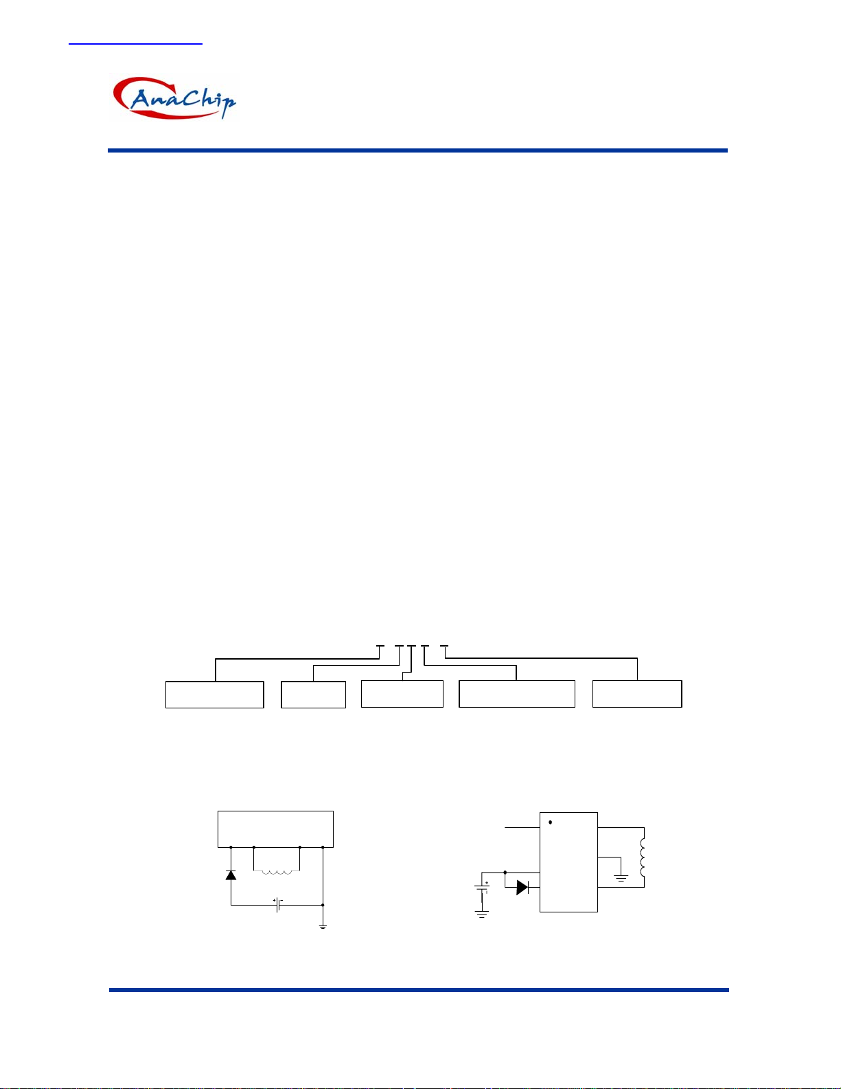
Application Circuit
12 34
coil
Vcc
FG
Vcc
(SIP-4L) (SOP 7)
Single-coil brush-less DC Fan
This datasheet contains new product information. Anachip Corp. reserves the rights to modify the product specification without notice. No liability is assumed as a result of the use of
this product. No rights under any patent accompany the sale of the product.
1/7
1
7
2
6
3
54
coil
Rev. A5 Apr 15, 2004
Page 2
ATC
Single Phase Hall Effect Latch ATS477
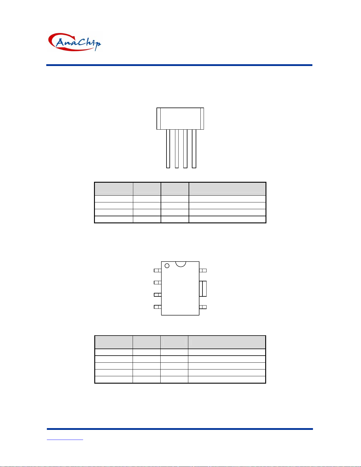
Pin Configuration
(1)SIP-4L
Front View
477
(2)SOP-7L
12 43
Name P/I/O Pin # Description
Vcc P 1 Positive Power Supply
DOB O 2 Output Pin
DO O 3 Output Pin
Vss P 4 Ground
Top view
1
7
2
477
6
3
54
Name P/I/O Pin # Description
Vcc P 3,4 Positive Power Supply
DO O 7 Output Pin
DOB O 5 Output Pin
FG O 1 Frequency Generator
Vss P 6 Ground
Anachip Corp.
www.anachip.com.tw
Rev. A5 Apr 15, 2004
2/7
Page 3

ATC
Single Phase Hall Effect Latch ATS477
Block Diagrams
(1). SIP-4L
1
1
OUTPUT(DOB)
REG.
2
(2). SOP-7L
3
REG.
Hall
Sensor
Hall
Sensor
Amp
Amp
CTL
CKT
CTL
CKT
1
OUTPUT(DO)
3
4
4
OUTPUT(DOB)
5
4
OUTPUT(DO)
7
6
VSS
VSS
Anachip Corp.
www.anachip.com.tw
FG
1
Rev. A5 Apr 15, 2004
3/7
Page 4

ATC
Single Phase Hall Effect Latch ATS477
Absolute Maximum Ratings ( at Ta=25
Characteristics Symbol Values Unit
Supply voltage VCC 20 V
Magnetic flux density
Continuous 250
Output “on” current
Operating temperature range
Storage temperature range
Package Power
Dissipation
(Note 1) Ground pin must connect to large area copper on PCB as possible.
Hold 300
Peak (Start Up)
SIP-4L 550 mW
SOP-7L
o
B
Ic
Ta
Ts
PD
C )
Unlimited
mA
600
-20~+85
-65~+150
800 mW (Note 1)
°C
°C
Electrical Characteristics ( Ta=+25°C, Vcc=3.5V to 20V )
Characteristic Symbol Test Conditions Min Typ Max Unit
Supply Voltage Vcc
Output Saturation
Voltage
FG Saturation Voltage Vce Vcc=14V, IFG=20mA 0.3 0.7 V
Supply Current Icc Vcc=20V, Output Open
Output Rise Time tr
Output Falling Time tf
Switch Time Differential
Vce(sink) Vcc=14V, Ic=200mA
Vce(drive) Vcc=14V, Ic=200mA Vcc-1.5
Vcc=14V, RL=820Ω, CL=20pF
Vcc=14V, RL=820Ω, CL=20pF
∆t Vcc=14V, RL=820Ω, CL=20pF
-
3.5
-
-
-
-
-
-
20 V
500 800 mV
-
Vcc V
18 30 mA
1.0 5.0 µs
0.3 1.5 µs
1.0 5.0 µs
Magnetic Characteristics (Ta=+25°C)
(1mT=10Gauss)
A grade
Characteristic Symbol Min. Typ. Max. Unit
Operate Point Bop 5 - 70 Gauss
Release Point Brp -70 - -5 Gauss
Hysteresis Bhy - 60 - Gauss
B grade
Characteristic Symbol Min. Typ. Max. Unit
Operate Point Bop - - 100 Gauss
Release Point Brp -100 - - Gauss
Hysteresis Bhy - 60 - Gauss
Anachip Corp.
www.anachip.com.tw
Rev. A5 Apr 15, 2004
4/7
Page 5

ATC
Single Phase Hall Effect Latch ATS477
DOB DO
HYSTERCSIS CHARACTERISTICS
RP
Output Voltage in Volts
ON
-100 0
Magnetic Flux Density in Gauss Magnetic Flux Density in Gauss
12
10
8
6
4
2
OFF
OP
Vsat Vsat
200100
Operation Characteristics
S
Marking side
N
S
Marking side
N
OFF
Output Voltage in Volts
RP
-200
-100 0-200
DO
V
cc
High
( Output Voltage )
V
sat
12
10
OP
8
6
4
2
ON
200100
V
d
B
hy
Low
( SIP4 ) ( SOP-7 )
Marking Information
Part Number
Anachip Corp.
www.anachip.com.tw
Rev. A5 Apr 15, 2004
( Top View )
477
X XX X X
5/7
B
rp
B
op
0
( Magnetic flux density )
Blank : normal
L : Lead Free Package
ID Code: A ~ Z
Nth week: 01~52
Year:
"1" = 2001
"2" = 2002
~
Page 6

ATC
Single Phase Hall Effect Latch ATS477
Package Information
(1) SIP-4L
Active Area Depth Package Sensor Location
Marking side
1.50mm
1.35mm
Package Dimension
0.30mm
+/-0.1mm
o
o
-7
0.7mm
1.55mm
+/-0.1mm
1.03mm
o3o
-55
+/-0.1
5.22mm
+/-0.1mm
4.20mm
+/-0.1mm
o
o
5
-7
o
3o -5
3.65mm
+/-0.1mm
477
0.46mm
+/-0.03mm
0.2mm Max.
1.42mm+/-0.1mm
1234
14.25mm
+/-1.25mm
0.38mm
+/-0.03mm
0.38mm
+/-0.03mm
1.27mm
+/-0.03mm
3.81mm
+/-0.03mm
Anachip Corp.
www.anachip.com.tw
Rev. A5 Apr 15, 2004
6/7
Page 7

ATC
Single Phase Hall Effect Latch ATS477
(2) SOP-7L
C2
A
β
C3
B1
B2
X
C1
C
Y
E
e
D
F
Symbol
Dimensions In Millimeters Dimensions In Inches
Min. Nom. Max. Min. Nom. Max.
A 5.79 5.99 6.19 0.228 0.236 0.244
B1 3.83 3.91 3.99 0.151 0.154 0.157
B2 3.78 3.86 3.94 0.149 0.152 0.155
C 4.80 4.87 4.94 0.189 0.192 0.194
C1 1.57 1.67 1.77 0.062 0.066 0.070
C2 0.32 0.40 0.48 0.013 0.016 0.019
C3 1.17 1.27 1.37 0.046 0.050 0.054
D 0.19 0.22 0.25 0.007 0.009 0.010
E 1.04REF 0.041REF
e 0.48 0.68 0.88 0.019 0.027 0.035
F 1.35 1.45 1.55 0.053 0.057 0.061
X - 2.90 - - 0.114 Y - 2.00 - - 0.079 -
β
o
7
7
o
Anachip Corp.
www.anachip.com.tw
Rev. A5 Apr 15, 2004
7/7
 Loading...