

Page 1
OPERATION:
The Model A655-8-3000 timer is a microprocessor-based
device capable of performing 2 different timing modes
over five different timing ranges.The timing ranges allow
for delays from 1 millisecond to 199 hours 59 minutes.
The timing modes and ranges are selected using a DIP
switch assembly located on the inside of the timer.
The time setting is entered through the front panel keypad while the time value is displayed on the LCD readout.
The timer keypad can be disabled to guard against accidental time changes by using the internal DIP switch.
The timer is housed in a standard 15-terminal plug-in
round case and can directly replace most existing electromechanical or electronic plug-in round case timers. A
totally sealed faceplate allows this timer to be used in
harsh environments.
Both instantaneous and timed contacts are provided and
A655 timer models are available for operation on either
120VAC or 240VAC.
SPECIFICATIONS
TIMING RANGES
0.001 sec. to 19.999 sec.
0.01 sec. to 199.99 sec.
0.1 sec. to 1999.9 sec.
1 sec. to 199 min., 59 sec.
1 min. to 199 hrs., 59 min.
TIMING MODES
On-Delay
Reverse Start, Delay
TIME SETTING
Front Panel Keypad
TIME REPEAT ACCURACY
±005 sec.
RESET TIME
25 milliseconds
CONTROL VOLTAGE INITIATE TIME
25 milliseconds
MEMORY
Replaceable Lithium Battery
OPERATING POWER
120 or 240VAC, +10%, -20%, 50/60Hz.
POWER CONSUMPTION
5.2VA
INSTANTANEOUS RELAY OUTPUT
7 Amps Resistive, 240VAC, 2 N.O.
2 N.C. Contacts
TIMED RELAY OUTPUT
7 Amps Resistive, 240VAC, 2 N.O.
2 N.C. Contacts
RELAY MECHANICAL LIFE
50,000,000 Operations
DISPLAY
LCD - 4 1/2 Digit, 7/16” High
TERMINATION
Screw Terminals
MOUNTING
Plug-in Case
SHORT CIRCUIT PROTECTION
1/4 Amp Fuse
TRANSIENT VOLTAGE
PROTECTION
Metal Oxide Varistor
OPERATING TEMPERATURE
0°-60°C
UL LISTING
File No. E104697
C-UL (Canada) LISTING
File No. E104697
NEMA RATING
NEMA 12
ORDERING INFORMATION
Part Number Description
655-8-3000 Timer 120 VAC, W/Battery
655-8-3001 Timer 240 VAC, W/Battery
651-3-0128 Gasket 1/8” Thick (Included With Timer)
651-3-0129 Gasket ¼” Thick (Included With Timer)
600-3-3950 Surface Mounting Bracket
652-3-0130 Battery (Included With Timer)
A655-8-1000/1001/3000/3001
INSTALLATION
INSTRUCTIONS
MARCH, 2001
A655
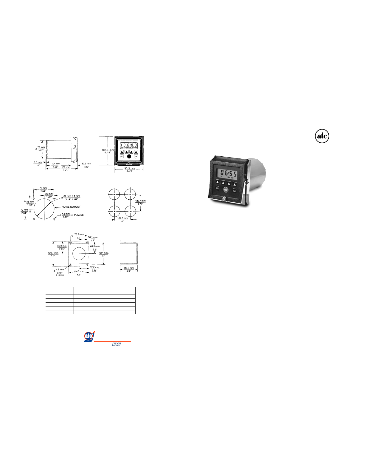
EXTERNAL DIMENSIONS
MOUNTING DIMENSIONS MINIMUM DIMENSIONS-MULTIPLE MOUNTINGS
MODEL A600-3-3950-SURFACE MOUNTING BRACKET
www.automatictiming-usa.com
(800) 576 - 6308
AUTOMATIC
TIMING & CONTROLS
Distributed By Inc,
Page 2
TIMING RANGE SELECTION
The Model A655 allows for the selection of five different
timing ranges. While operating in the “Hours:Minutes”
range, the colon will flash to give an indication that timing
is taking place. The correct timing range is selected using
switches #1, #2 and #3 on the seven switch DIP assembly
located on the inside of the timer. See the chart for the
correct switch settings.
TIME RANGE SELECTION CHART
SW1 SW2 SW3 TIMING RANGE
OFF OFF OFF 0.001 – 19.999 Sec.
OFF OFF ON 0.01 – 199.99 Sec.
OFF ON OFF 0.1 – 1999.9 Sec.
OFF ON ON 1 Sec.-190 Min., 59 Sec.
ON OFF OFF 1 Min.-199 Hrs., 59 Sec.
Note: OFF = Open ON = Closed
KEYPAD LOCKOUT SELECTION
The Keypad can be disabled to guard against accidental
changes by using switch #4 on the five switch DIP
assembly located on the inside of the timer. See the
chart below for the correct switch setting.
SW4 KEYPAD LOCKOUT
OFF Keypad Enabled
ON Keypad Disabled
Note: OFF = Open ON = Closed
PROGRAMMING THE TIME
After the timing mode and the timing range have both
been selected, the proper time delay value can now be
programmed.
The Model A655-8-3000 is equipped with a 10-year life,
replaceable lithium battery and can be programmed without an outside power source. To program push the "SET"
button and the display will illuminate the timing range
selected. Four dashes will also appear indicating that no
set point is presently programmed. Depress the "SET" key
a second time and the word "SET" will now be illuminated
on the display along with four zeros. The desired time
value is now entered using the four increment keys.
Each key controls its own digit with the exception of the
left increment key which is used to set the left most 1 and
½ digits on the display (these increment to 19 before
returning to 0). With a timing range of “MIN:SEC” or
“HR:MIN”, the digit to the right of the colon will roll over
from 5 to 0. Holding a key depressed for longer than 1
second causes the digit to automatically increment at
the rate of 2 numbers per second until released. When
the digits on the display correspond to the desired time
value, pressing the “ENT” key will enter that value into
the memory.
The set point can be changed without interrupting the
timing cycle by following the normal programming procedure. This new value will then be used on the next timing
cycle.
The set point can also be viewed without interrupting the
timing cycle by depressing the “SET” key. Press the
“ENT” key to return the display to the time remaining.
If the keypad lockout is enabled, you can still view the set
point by depressing the “SET” key but the set point cannot
be changed using the increment keys. To indicate that the
keypad is locked while a programmed value is being
viewed, the display alternates the numerical value with
the word “LOC”.
POWER FAILURE
If all power is lost during a timing cycle, the instantaneous
contacts will transfer back to their original state. When
power is restored, the timer will reset back to the set point
if programmed for “standard start” or continue from the
point of power interruption if programmed to “reverse
start”. The timer set point will be maintained.
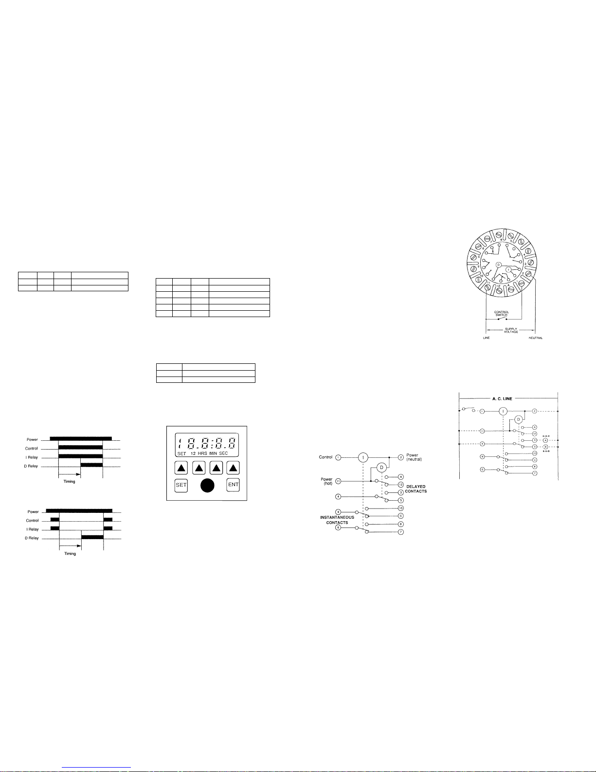
INTERNAL SCHEMATIC
WIRING CONNECTIONS
Note: It is important that the metal bracket on the front of
the case be connected to earth ground. Mounting the
A655 in a grounded metal panel is satisfactory.
TYPICAL WIRING DIAGRAM
Dotted Lines Are External Wiring
Sustained Control Switch
Standard Start Close to run and
Open to reset
Reverse Start Close to reset and
Open to run
The above diagram shows the typical timer wiring for a
simple application involving the delayed closing and
opening of load circuits. Contacts may be wired in series
to achieve various timing schemes.
TIMING MODE SELECTION
The Model A655 is capable of performing two different
modes of timing operation; On-Delay, or Reverse Start,
Delay. The selection of the timing mode is accomplished
by setting DIP switches 5, 6 and 7 on the switch assembly
that is accessed when the timer is removed from its
mounting case.
SW5 SW6 SW7 TIMING MODE
OFF OFF OFF On-Delay
OFF ON OFF Reverse Start, Delay
Note: OFF = Open ON = Closed
TIMING MODE DEFINITION
ON-DELAY
The supply voltage is applied at all times. When voltage
is applied to the control terminal, the instantaneous
contacts change state and timing begins. At the
completion of the timing period, the timed contacts
change state. Reset takes place upon removal of the
control voltage.
REVERSE START, DELAY
The supply voltage is applied at all times. When voltage
is applied to the control terminal, the instantaneous
contacts change state. When the voltage is removed
from the control terminal, the instantaneous contacts
change back to their original state and timing begins. At
the completion of the timing period, the timed contacts
change state. Reset takes place when voltage is once
again applied to the control terminal.
TIMING RANGES
ON-DELAY
REVERSE START, DELAY
INSTALLATION INSTRUCTIONS–A655-8-1000/1001/3000/3001 INSTALLATION INSTRUCTIONS–A655-8-1000/1001/3000/3001
www.automatictiming-usa.com
www.automatictiming-usa.com
 Loading...