

Page 1

6254M Mainboard Contents
1
CONTENTS
COMPONENT LOCATION DIAGRAM………………..…..…A
CHECK LIST OF THE PACKAGING…………..……………..B
CONNECTORS DESCRIPTION ……………………….….….. C
TABLE OF CONTENTS…………………………………….…..1
HOW TO USE THIS MANUAL……………….………….…….2
CHAPTER 1 Introduction……………………………..……..3
1-1 System Features ..........................................................................3
German.....................................................................................4
French......................................................................................5
Spanish.....................................................................................6
Italian........................................................................................7
1-2 Software Power Off Control........................................................9
1-3 Fan Off Control...........................................................................9
1-4 Running 100MHz CPU Bus (JP11).............................................10
1-5 Keyboard & PS/2 Mouse Power On (JP9) ..................................11
1-6 Wake-On-LAN ........................................................................12
1-7 Thermister (optional )..................................................................12
1-8 LDCM ( LANDesk Client Manager, optional )..............................13
CHAPTER 2 Installation..............................................................14
2-1 Installation Procedure ..............................................................14
2-2 CPU Installation........................................................................14
2-2-1 Core/Bus Freq. Ratio…………………………………….…….14
2-2-2 CPU Setting……………………………………………………15
2-3 System Memory Installation......................................................16
2-4 IDE Driver Installation...............................................................17
2-5 Sound Driver Installation ...........................................................17
2-6 VGA Driver Installation.............................................................18
2-7 Hardware Doctor Installation .....................................................18
CHAPTER 3 Award BIOS Setup ................................................ 19
3-1 Update BIOS Procedure............................................................20
3-1-2 Update Microcode API...........................................................21
3-2 Award System BIOS Configuration Setup ..................................22
Appendix A How to Install PentiumII/IIICeleron and
Processors with SECC2 Package
Appendix B How to Setup Thermister (optional)
Page 2

How To Use This Manual 6254M Mainboard
2
Appendix C Technical Support Request Form
HOW TO USE THIS MANUAL
This manual is written in a user-friendly style. It would be advisable
for users to read it in an orderly sequence :
1. For Hardware Information:
Read Page A: COMPONENT LOCATION DIAGRAM, Page B: CHECK LIST OF
THE PACKAGING and Page C: CONNECTORS DESCRIPTION.
2. For Mainboard and System Features:
Read “Chapter 1 Introduction” in detail, and you will find helpful information on
mainboard and system features. Especially, when you want to do some feature setup,
detailed instructions are provided therein to help you through.
3. For CPU, Memory and Drivers Installation:
Read “Chapter 2 Installation” for your CPU, memory and application drivers
installation. Detailed instructions are provided to guide all kinds of users.
4. For BIOS Update and Setup:
Read “Chapter 3 Award BIOS Setup” for updating your mainboard BIOS and
setting up your BIOS Configuration.
5. For Installing PentiumII/III, Celeron or Processors with SECC2 Package:
Read APPENDIX A for setting up Intel PentiumIII, PentiumII, CeleronTM, or
processors with SECC2 package.
6. For Installing Thermister:
Read APPENDIX B for thermister installation. You will find that the self -explanatory
drawings enclosed therein make the job easy and simple.
7. For other Technical Support:
Read APPENDIX C, fill and send the Request Form to your dealer for other technical
support.
It is often heard that the default setting on a mainboard is not what user expects. A
user-friendly manual would be the handiest assistant to help change the on-board
configuration or default setting. In case this manual cannot solve all your problems,
please ask your dealer for help and be sure the warranty on your system is still valid.
REMARK: Intel® is a registered trademark of Intel Corporat ion.
Page 3

6254M Mainboard Chapter 1 Introduction
3
All other brands and product names are registered trademarks of their respective companies.
Page 4

6254M Mainboard Chapter 1 Introd uction
4
CHAPTER 1 INTRODUCTION
Welcome to utilize 6254M mainboard, the Intel 440BX chipset supporting
both 66MHz and 100MHz Front Side Bus PentiumII/III CPU. It also has the
built-in Yamaha YMF 724/740 3D PCI sound chip and Voodoo3 VGA chip.
The Yamaha YMF 724/740 sound chip is using PCI interface which allows
your computer to perform 3D stereo sound. And the Voodoo3 3D VGA chip
working with AGP interface technique allows users to have 2D/3D display
resolution without plug any of VGA cards.
1-1 System Features
: CPU Slot supporting Intel PentiumIII CPU 450Mhz to 550MHz, PentiumII CPU
233MHz to 450MHz and Intel Celeron CPU 266MHz to 466MHz.
: Intel 440BX AGPset.
: Yamaha YMF 724/740 3D PCI Sound Chip.
: Onboard 3Dfx Voodoo3 with onboard 16MB SGRAM.
: Four 168-pin DIMM Sockets in four banks of 64-bit wide path up to 512MB
SDRAM or 1GB registered SDRAM (with parity chip ECC support).
: Built-in Switching Voltage Regulator.(VRM 8.2 SPEC.)
: Auto-detect CPU core voltage range from 1.8V to 3.5V.
: Two16-bit ISA slots and four PCI slots compliance with reversion 2.2 of the PCI
Local Bus specification.
: Dual Master IDE connectors support Ultra DMA/33 (33MB/sec), up to four
devices in two channels for connecting high capacity hard disk, CD-ROM,
LS-120MB floppy drive, tape backup etc.
: Winbond 83977 high-speed Ultra Multi-I/O chipset.
: ATX Power Connector.
: USB (Universal Serial Bus) Connector supporting up to 127 peripheral devices.
: PS/2 Keyboard Connector and PS/2 Mouse Connector.
: Infrared Transfer (IrDA TX/RX) Connector.
: One FDD Port supporting two devices available for 1.2MB, 1.44MB and 2.88MB.
: Two 16550A fast UARTs compatible Serial Ports.
: One EPP/ECP mode Parallel Printer Port.
: Software Power Off Control; Modem Ring On; SB-Link; Keyboard & PS/2 Power
On; Wake-On-LAN functions.
: Built-in Hardware Health Monitor chip. (optional )
: Intel LDCM software. (optional )
: ATX Form Factor; Hardware Dimension is 305mm x 210mm. (12" x 8.26")
Page 5

6254M Mainboard Chapter 1 Introduction
5
1-1 Systemmerkmale (German)
: CPU Slot unterstützt Intel Pentium III CPU 450MHz zu 550MHz,
Pentium II CPU 233MHz zu 450MHz und Inetl Celeron
CPU 266MHz zu 466MHz .
: Intel 440BX AGPset .
: YAMAHA YMF 724/740 dreidimensional PCI Sound Chip .
: An Board dreidimesional fx Voodoo3 mit 16MB SGRAM .
: Vier 168-pin DIMM Sockets in vier Banks für 64-bit Breit
ausgedehnte Bahn hoch bis zu 512MB SDRAM oder 1GB
registriend SDram ( mit ECC Chip in Gleichheit unterstützt ).
: Built-in schaltet den Voltageregulator .( VRM 8.2 SPEC )
: Selbstnachweisend CPU Kernvoltage variiert zwischen 1.8V und
3.5V .
: Zwei 16-bit ISA Slots und vier PCI Slots sind Wünschen gemäß der Umkehrung
2.2 für PCI Lokalbus in Spezifizierung .
: Dual Master IDE Anschließstück unterstützen Ultra DMA/33
(3MB/sec ), hoch bis zu vier Vorrichtungen in zwei Kanälen ,
das Einsetzten der Hardscheibe ist in hoherAufnahmfäigkeit,
CD-Rom, LS -120MB Softwaredrive , Tapereserven etc.
: Winbond 83977 hohe-Tempi Ultra multi-I/O Chipset .
: ATX Power schließen sich an .
: USB (universale Seriennummer-Bus ) Anschlußstück wird Randverrichtung hoch
bis zu 127 untergestützt .
: PS/2 Keyboard Anschlußstück und PS/2 Mouse Anschlußstück .
: Übertragend(IrDA TX/RX) Anschlußstück .
: One FDD Schließloch unterstützt zwei verwendbare Vorrichtungen
für 1.2MB , 1.44MB und 2.88MB.
: Zwei 16550A rapide UARTs vertragende Seriennummer der
Schließlöchern .
: Ein EPP/ECP Model mit parallelem Printerschließloch .
: Abschalten zu Software ist kontrolliertbar ; Modem mit Signalklang ;
SB-Anschließen ; Keyboad und PS/2 Einschalten ;
: Wake-On-LAN Funktion .
: Konstruktion -in Hardware mit gesundheitlichem Monitor Chip.
( freigestellt)
: Intel LDCM Software .( freigestellt)
: ATX Form Faktor ; Hardware Dimension ist 305mm x 210mm.
(12" x 8.26")
Page 6

Chapter 1 Introduction 6254M Mainboard
6
1-1 Caractéristiques du Système (French)
: Socle CPU supportant un CPU d'Intel Pentium®III 450Mhz à 550Mhz, un CPU
d'Intel Pentium®II 233Mhz à 450Mhz et un CPU d'Intel Celeron™ 266Mhz à
466Mhz.
: Puce Intel 440BX AGP.
: Puce sonore YMF 724/740 3D PCI de YAMAHA.
: 3 Dfx Voodoo3 Sur Carte avec 16MB de SGRAM Sur Carte.
: Quatre Socles DIMM 168-broches dans quatre banques d'une piste de 64-bit sur
512MB de SDRAM ou 1GB de SDRAM enregistrée ( avec support ECC de puce
par paire ).
: Régulateur de voltage interchangeant incorporé ( VRM 8.2 SPEC ).
: Gamme du voltage détecté par le CPU de 1,8V à 3,5V.
: Deux socles ISA 16-bit et quatre socles PCI conformes avec l'inversion 2.2 des
spécifications du Bus PCI Local.
: Double connecteurs maîtres IDE avec support d'Ultra DMA/33 ( 33MB/sec.) sur
quatre périphériques dans deux chaînes pour connecter un disque dur de grande
capacité, un lecteur de CD-ROM, de disquette LS -120MB, une machine pour copie
de secours, etc.
: Jeu de puces Ultra Multi-I/O haute vitesse Winbond 83977.
: Connecteur d'alimentationATX.
: Connecteur USB ( Bus Sériel Universel ) supportant plus de 127 périphériques.
: Commecteur de clavier PS/2 et connecteur de souris PS/2.
: Connecteur de transfert d'infrarouge ( IrDA TX/RX ).
: Un port FDD supportant deux périphériques disponibles pour 1,2MB, 1,44MB et
2,88MB.
: Deux ports sériels compatibles 16550A fast UARTs.
: Un Port d'Imprimante Parllèle mode EPP/ECP.
: Logiciel de contrôle d'arrêt; Sonnerie de modem; Lien SB; Clavier & PS/2 Marche;
Fonctions LAN de Réveil.
: Puce d'état du moniteur et du matériel ( optionnelle ).
: Logiciel Intel LDCM ( optionnel ).
: Facteur de Forme ATX; dimensions du matériel: 305mm x 210mm ( 12" x 8,26" ).
Page 7

6254M Mainboard Chapter 1 Introduction
7
1-1 Características del Sistema (Spanish)
: Ranura CPU soporta Intel Pentium®III CPU 450Mhz a 550Mhz, Pentium®II CPU
233Mhz a 450Mhz e Intel CeleronTM CPU 266Mhz a 466Mhz.
: Intel 440BX AGPset.
: Chip de sonido Yamaha YMF 724/740 3D PCI
: 3Dfx Voodoo3 abordo con 16MB SGRAM abordo
: Cuatro Casquillos 168-pin DIMM en cuatro bancos de 64-bit camino ancho hasta
512MB SDRAM o 1GB registrado SDRAM (con soporte de chip de paridad
ECC)
: Regulador de Voltaje Incorporado (VRM 8.2 SPEC.)
: Autodetección de rango de voltaje central de CUP de 1.8V a 3.5V
: Dos ranuras 16-bit ISA y cuatro ranuras PCI conforme a la reversión 2.2 de la
especificación de PCI Local Bus
: Conectores IDE Master Duales soportan Ultra DMA/33 (33MB/seg.), hasta cuatro
dispositivos en dos canales para conectar disco rígido de alta capacidad,
CD-ROM, lector de floppy LS -120MB, respaldo de cinta, etc.
: Chipset Ultra Multi-I/O de alta velocidad Winbond 83977.
: Conector de alimentación ATX.
: Conector USB (Bus Serial Universal) que soporta hasta 127 dispositivos
periféricos.
: Contector de Teclado PS/2 y Conector de Ratón PS/2.
: Conector de Transferencia Infrarroja (IrDA TX/RX).
: Un puerto FDD que soporta dos dispositivos disponibles para 1. 2MB, 1.33MB y
2.88MB.
: Dos Puertos Seriales 16550A fast UARTs compatibles.
: Un Puerto de Impresora Paralelo en modalidad EPP/ECP.
: Control de Apagado en Software; Encendido de Módem; SB-Link; Teclado &
Encendido PS/2; Despertar en LAN.
: Chip de Monitor de Salu d de Hardware incorporado, (opcional)
: Software Intel LDCM, (opcional)
: Factor de Forma ATX; Dimensión de Hardware es 305mm x 210mm (12” x 8.26”)
Page 8

Chapter 1 Introduction 6254M Mainboard
8
1-1 Caratteristiche del Sistema (Italian)
: La slot CPU supporta micro-processori Intel Pentium III Cpu da 450 Mhz a 550
Mhz, Pentium II CPU da 233 Mhz a 450 Mhz ed Intel Celeron CPU da 266 Mhz a
466 Mhz.
: Set Intel 440BX AGP.
: PCI Chip suono Yamaha YMF 724/740 3D.
: 3Dfx Vodoo3 caricato con 16MB SGRAM caricate.
: Quattro prese DIMM a 168 pin, a disposizione quadrupla, con 64 bit di ampiezza
fino a 512MB SDRAM oppure 1GB registrato SDRAM (con chip parità supporto
ECC).
: Regolatore Voltaggio Aggiustabile internamente costruito (VRM 8.2 SPEC.)
: Auto-lettura voltaggio interno CPU con ampiezza da 1.8V a 3.5V.
: Due prese ISA da 16-bit e quattro prese PCI conformi a reversione 2.2 della
specifica di PC Local Bus.
: Connettori Dual Master IDE supportanti Ultra DMA/33 (33 MB/sec), fino a due
dispositivi in due canali per la connessione di hard disk ad alta capacità, CD-ROM,
floppy drive LS -120 MB, backup di nastro, ecc.
: Winbond 83977 alta velocità Ultra Multi-I/O chipset.
: Connettore di alimentazione ATX.
: Connettore USB (Universal Serial Bus = Bus Seriale Universale) in grado
disupportare un massimo di a 127 dispositivi periferici.
: Connettore Tastiera PS/2 e Connettore Mouse PS/2.
: Connettore Transfer Infrarossi (IrDA TX/RX).
: Un porto FDD che supporta due dispositivi disponibile per 1.2MB, 1.44MB e
2.88MB.
: Due Porti Seriali compatibili con 16550A fast UARTs
: Un porto con mode EPP/ECP Stamp ante Parallela.
: Dispositivo controllo spegnimento software; accensione suono Modem; SB-Link;
accensione tastiera e PS/2; funzioni Wake-On-LAN.
: Chip per controllo di condizione dell’ Hardware (Hardware Health Control -
opzionale).
: Software Intel LDCM (opzionale).
: Fattore Forma ATX; le dimensioni dell’ hardware sono 305mm x 210mm (12” x
8.26”).
Page 9

6254M Mainboard Chapter 1 Introduction
9
Voodoo III – 2000/3000 Features
: Fully integrated 128-bit
: VGA/2D/3D/Video accelerator
: True Multi-exturing-2 textures/ clock
: 3Dfx Voodoo compatibility.
: 2X AGP with sidebands.
: DVD Acceleration.
: Digital video output for NTSC, PAL and SECAM TV-out support.
: Digital LCD support (LCDfxTM)
: DirectX 6, Open GL, Glide 2.x/3.x support.
: 0.25 Micron, 5-layer metal CMOS technology.
: 2000: 4 million triangles/sec., 250 Megatexels/sec.
3000: >7 million triangles/sec., > 366 Megatexels/sec.
: 2000: 300MHz RAMDAC, 2048x1536@65Hz.
3000: 350MHz RAMDAC, 2048x1536@75Hz.
: 2000: 125MHz Core Graphics Clock
3000: 183MHz Core Graphics Clock
Audio Features
: True Full Duplex Playback and Capture with different Sampling Rate
: Maximum 32-voice XG capital Wavetable
: Synthesizer including GM compatibility
: DirectSound Hardware Acceleration
: DirectMusic Hardware Acceleration
: Downloadable Sound (DLS) level-1
: Genuine OPL3
: Hardware Sound Blaster Pro compatibility
: Joystick
: Supporting PC/PCI and Distributed DMA for legacy DMAC (8237) emulation
: Supporting Serialized IRQ
: Supporting AC -2 Interface (AC-Link)
: Single Crystal operation (24.576MHz)
: 5V Power supply for I/O; 3.3V Power supply for Internal core logic
Page 10

Chapter 1 Introduction 6254M Mainboard
10
1-2 Softwa re Power Off Control
The mainboard design supports Software Power Off Control feature through the
SMM code in the BIOS under Windows 95/98, and MS-DOS operation system
environment.
First, you should connect the power switch cable to the connector “PS-ON” on
the mainboard. In the BIOS screen of POWER MANAGEMENT SETUP’, choose
“User Define” (or “Min. Power Saving” or “Max. Power Saving”) in ‘Power Manager’
and pick up “Yes” in ‘PM Control by APM’.
In Windows 95/98, if you would like to power off the system, you just need to
choose “shutdown the computer ?” in the “Shut Down Windows“ from Windows
95/98. Then the system power will be off directly, and become to the stand -by status.
If you would like to restart the system, just press the power switch button, and the
system will be powered on.
Note : If you are going to leave your system idle for several days, we suggest you
use hardware power off to shutdown your system.
Status Power LED Light Turbo LED Light
Software power off
control
Blinking (JP5, pin1-2)
Light off (JP5, pin2-3)
Light off
APM mode Light on Light on
System running Light on Light on
* Under Software power off control, the status of Power LED Light depends on the setting of JP5.
If you set JP5 to “pin1-2” position, it is blinking. Otherwise, it is light off.
1-3 Fan Off Control
With fan-off function, the CPU cooling fan can turn off automatically even when
the system is in suspend mode. This function is able to reduce energy consumption
and system noise.
Because it is a feature of advanced BIOS, you should set this option enabled
through “Power Management Setup” from the BIOS setup screen.
Page 11
6254M Mainboard Chapter 1 Introduction
11
1-4 Running 100 MHz CPU Bus (with JP11)
The mainboard provides Jumper 11 that allows you to set your CPU host clock
and perform CPU overclock function. There are two ways to set CPU host clock at
‘closed’ and ‘open’. When setting ‘closed’, the system will automatically detect the
CPU host clock, for instance 66MHz and 100MHz. Another way is to set Jumper 1 1 at
‘open’ for 66MHz CPU overclock to 100MHz.
We recommend that users should use Intel PentiumII/III 100 MHz CPU, running
at 350, 400, 450 and 500MHz internal clock speed. Moreover, the SDRAM memory
module must be 8 nano-second (Maximum Frequency 125 MHz) speed of
memory –die or less. However, based on Intel’s design, we don’t recommend users to
run over 100MHz CPU host bus.
Please note that the default setting of Jumper 11 is ‘closed’.
Jumper 11 BASE CLK
Closed Auto (default)
Open Overclock (66MHz àà 100MHz)
(a) Pin Closed (b) Pin Open
Slot 1
JP11
--If you would like to run over 100MHz CPU host bus, like 112 and 124MHz, please
set “CPU Clock Frequency” in “CHIPSET FEATURES SETUP” from the
BIOS setup screen. If the system can’t boot up with the clock frequency that you
set to, you can clear the set frequency by pressing the ‘Insert” key on keyboard.
After restarting the system, you have the system operating at the default
frequency.
Page 12
Chapter 1 Introduction 6254M Mainboard
12
1-5 Keyboard & PS/2 Mouse Power On (with JP9)
With ATX Power Supply and Jumper 9 set to Pin 1-2 closed, 6254M Mainboard
is enabled to Keyboard & PS/2 Mouse Power On functions :
JP 9 KB & PS/2 Mouse Wakeup
1-2 Enable
2-3 Disable
(a) Enable (1-2 closed) (b) Disable (2-3 closed)
The default Power On function is “Button Only”. That means, we can only turn
our computer on and off by pressing the “Power Button”. If we want to enable KB &
PS/2 Mouse Power On function, we first have to set JP9 to Pin 1-2 closed, and then go
to “Power On Function” in “Integrated Peripherals” of Award BIOS Setup. At the line
“Power On Function”, we can press “Page Up” or Page Down” to make the following
selections:
1. Password(via Keyboard):
When us er selects “Password”, it will show “Enter Password:”. After user has typed
the password, screen will show “ Confirm Password:” and user has to type the same
password to confirm it. Save selection and shut down system. Now computer will
only be powered on by entering correct password.
In case the set password is forgotten, carry out “Clear CMOS” (Page 14) to clear
password, or computer can not be powered on.
2. Hot Key (via Keyboard):
When user selects this option, screen will show another line : “Hot Key Power ON :
Ctrl -F1”. User can select from “Ctrl-F1” to “Ctrl-F12” as Hot Key by pressing
PageUp / PageDown. After fixing Hot Key, save selection and shut down system.
Now computer will only be powered on by pressing the correct Hot Key.
3. Mouse Left, Mouse Rig ht (via PS/2 Mouse):
This function is available via PS/2 mouse only. User can select either “Mouse Left”
or “Mouse Right” from the “Power On Function” line. After picking either option,
save selection and shut down system. Now computer will only be powered on by
double-clicking the correct PS/2 Mouse button.
Do not slide the mouse when you click; or you can’t power on the system.
4. Button Only (via Power Button): “Button Only” is default setting, at which
computer can only be on/off via Power Button.
JP9
PCI slots
Page 13

6254M Mainboard Chapter 1 Introduction
13
1-6 Wake-On-LAN
The remote Wake-On-LAN (WOL) mode of operation is a mechanism that uses
Advanced Micro Device Magic Packet technology to power on a sleeping workstation
on the network. This mechanism is accomplished when the LAN card receives a
specific packet of information, called a Magic Packet, addressed to the node on the
network. For additional protection, Secure ON is an optional security feature that can
be added to the Magic Packet that requires a password to power on the sleeping
workstation. When LAN card is in remote Wake-On-LAN mode, main system power
can be shut down leaving power only for the LAN card and auxiliary power
recondition.
The LAN card performs no network activities while in the remote Wake-On-LAN
mode of operation. It only monitors the network for receipt of a Magic Packet. If a
Magic Packet is addressed to the LAN card on the network, the LAN card wake up the
system. If the Secure ON feature has been enabled, the password added to the Magic
Packet is also verified prior to waking up the system.
You should select two kinds of PCI Ethernet cards with WOL function. One is
Intel and the other is with PME signal supporting. And you can set “Wake Up On
LAN” this function enabled through “ Power Management Setup” from the BIOS setup
screen.
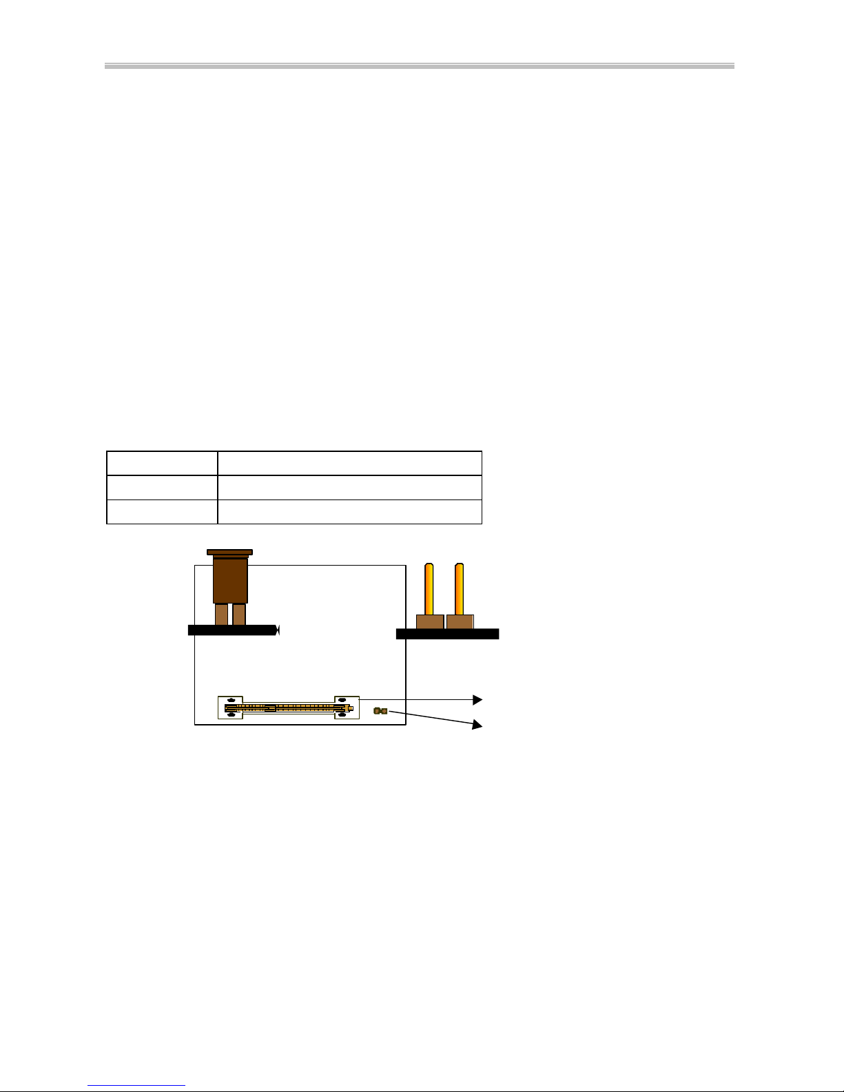
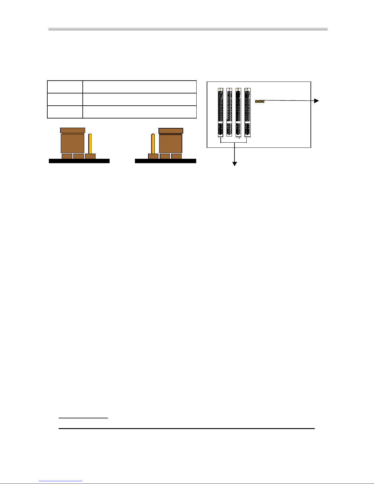
1-7 Thermister
(optional)
If Hardware Monitor is built onboard, CPU temperature can be monitored by
setting up the Thermister.
When setting up the thermister (refer to Appendix B), the BIOS will load the CPU
temperature automatically. A warning beep sound will be sent out if the user set the
option on. If the CPU is overheated, the user will get the warning. Then you should
shut down computer and check your devices. Or contact you dealer for further help if
CPU temperature persists.
Note: If you would like to enable the function of hardware monitor, to set up
thermister beforehand is necessary. RT2 is the thermister connector.
Page 14

Chapter 1 Introduction 6254M Mainboard
14
1-8 LDCM
LANDesk Client Manager(optional)
The mainboard built -in controller supports Intel LDCM. LDCM can satisfy users
who want manageable systems that can interact automatically with the user. Client
manager is the answer, enabling both administrators and clients to manage systems.
The features of LDCM are as following :
View system inventory
Client Manager enables you to view hundreds of inventoried items. Some of these
items are software related, while many others are hardware related.
View DMI-compliant component information
Client manager enables you to view component information that is compliant with the
Desktop Manager InterfaceDMI. This means you can manage third-party
DMI-compliant components which did not include Client manager.
Back up and restore system configuration files.
Client Manager enables you back up and restore system configuration files. Whenever
you plan on changing the system configuration , you can make a backup set. If the
system no longer works correctly, after you the change the system configuration ,
you can simply restore the system configuration with the backup set.
Troubleshoot
Since Client manager enables you to view the system inventory, you can easily
troubleshoot system problems.
Receive notifications for system events
Client manager enables you to receive notification of certain system events. For
example, if the system is running low on virtual memory, you are notified of the
potential problem.
Transfer files to and from client workstations
As an administrator, you have the ability to transfer files to and from client workstation.
This is helpful, for example, when you need to update a clie nt workstation driver.
Remotely reboot client workstations
Administrator also have the ability to remotely reboot a workstation. This is helpful
when you want your system configuration changes to take effect.
Page 15

Chapter 2 Installation 6254M Mainboard
15
CHAPTER 2 INSTALLATION
2-1 INSTALLATION PROCEDURE
Before installing the computer, please prepare all components such as CPU, DRAM;
peripherals such as hard disk, keyboard, CD-ROM and accessories such as cables.
Then, install the system as following:
ΠPlug CPU/ heat sink (refer to PentiumII/III & CeleronTM installation
guide, Appendix A), and DRAM modules on the mainboard.
• Set DIP switch & jumpers based on your configuration.
Ž Plug add-on cards into PCI/ISA slots, if needed.
• Connect cables to peripheral devices , especially for power supply.
• Make sure all components and devices are well connected, turn on the
power and setup System BIOS based on your configuration.
‘ Install peripheral devices , add-on card drivers and test them.
’ If all of above procedures are running successfully, turn the power off
and screw the chassis cover to the chassis, and then connect external
devices which are cabled to the system.
2-2 CPU INSTALLATION
The mainboard has built-in VID (Voltage Identify) function to automatically detect
CPU voltages. Thus you do not have to set the CPU voltage setting.
2-2-1 CPU Core/Bus Freq. Ratio :
SW1
1-1
1-2
1-3
1-4
3.0x ON ON OFF OFF
3.5x ON ON ON OFF
4.0x OFF OFF OFF OFF
4.5x OFF OFF ON OFF
5.0x OFF ON OFF OFF
5.5x OFF ON ON OFF
6.0x ON OFF OFF ON
6.5x ON OFF ON ON
7.0x ON ON OFF ON
7.5x ON ON ON ON
8.0x OFF OFF OFF ON
Page 16

Chapter 2 Installation 6254M Mainboard
16
2-2-2 CPU Setting
a. For 233~333MHz Intel Pentium
II & 266~466MHz CeleronTM CPUs.
INTERNAL CPU CLOCK SW1
233MHz (66x3.5)
266MHz (66x4.0)
300MHz (66x4.5)
333MHz (66x5.0)
366MHz (66x5.5)
400MHz (66x6.0)
433MHz (66x6.5)
466MHz (66x7 .0)
b. For 350~450MHz Intel Pentium
II and 450~550MHz Pentium III CPUs.
INTERNAL CPU CLOCK SW1
350MHz (100x3.5)
400MHz (100x4.0)
450MHz (100x4.5)
500MHz (100x5.0)
550MHz (100x5.5)
1 2 3 4
ON
OFF
1 2 3 4
ON
OFF
1 2 3 4
ON
OFF
1 2 3 4
ON
OFF
1 2 3 4
ON
OFF
1 2 3 4
ON
OFF
1 2 3 4
ON
OFF
1 2 3 4
ON
OFF
1 2 3 4
ON
OFF
1 2 3 4
ON
OFF
1 2 3 4
ON
OFF
1 2 3 4
ON
OFF
1 2 3 4
ON
OFF
Page 17

6254M Mainboard Chapter 2 Installation
17
2-3 SYSTEM MEMORY INSTALLATION
The Mainboard provides four 168-pin DIMM sockets for system memory
expansion from 8MB to 512MB SDRAM, 1GB registered SDRAM or 1GB EDO
DRAM. (EDO DRAM is available for 66MHz processors only.) These four DIMMs
are arranged to four banks, please refer to page A.
Bank/DIMM Memory Module Total Memory
Bank0/DIMM1 8/16/32/64/128/256MB 8MB~256MB
Bank1/DIMM2 8/16/32/64/128/256MB 8MB~256MB
Bank2/DIMM3 8/16/32/64/128/256MB 8MB~256MB
Bank3/DIMM4 8/16/32/64/128/256MB 8MB~256MB
Total System Memory 8MB~1GB
DRAM type, size, parity supported:
6 EDO DRAM: for 66MHz system frequency only
6 Unbuffered, registered SDRAM with SPD
6 Both parity or non-parity are available.
6 3.3V, Single/double -side, 8/16/32/64/128/256Mbytes
(Max. memory size: 256MB registered SDRAM or EDO DRAM)
6 Both 4Mbx4 and 16Mbx4 (Each side has 16 chips.) SDRAM devices are
supported in the form of Registered DIMMs only.
u For 66MHz host bus CPUs use 12ns or faster DIMM module;
u For 100MHz host bus CPUs use 10ns or faster and PC-100 compliant modules .
@@ SPD (Serial Presence Detect)
This EPROM contains speed and design information of the memory module. The
mainboard may get optimal performance via accessing the data of SPD.
@@ ECC (Error Check and Correction)
This mainboard can support the ECC function while utilizing parity modules. To enable
this function, users must set “DRAM Data Integrity Mode” to “ECC” through “Chipset
Features Setup ” from the BIOS setup screen. All in all, ECC’s function is to detect and
correct the errors of transfer data.
Page 18

Chapter 2 Installation 6254M Mainboard
18
2-4 IDE DRIVER INSTALLATION
Setup for Windows 95/98 :
1. Start Windows 95/98.
2. Put the All-In-One CD into your CD-ROM drive.
3. Select “START”, “RUN”.
4. Type “D:\IDE\WIN95\SETUP.EXE” or “E:\IDE\WIN95\SETUP.EXE”.
(If your operating system is Win95, please type “D or E:\winp2x4.exe”
before you install IDE driver. )
5. Restart the computer, then follow the instructions on your screen to install
new IDE driver we offer in the All-In-One CD.
6. Exit Windows 95/98, turn power off; then turn power on.
2-5 YAMAHA SOUND DRIVER INSTALLATION
2-5-1 Installing Yamaha 724/740 PCI Driver for WinNT
Yamaha Sound 724/740 PCI Driver for WinNT is included in the
Driver/Utility CD under the autorun main menu “Install Yamaha 724/740 PCI
Driver”. To install this driver, just take the following steps:
1. Start WinNT 4.0 and insert the Driver/Utility CD into your CD-ROM Drive.
2. The screen will automatically show the autorun main menu which includes
“Install Yamaha 724/740 PCI Driver”.
3. Click this item and “Yamaha DS -XG Setup” screen will display.
4. Click “Windows NT4.0 Driver” and driver setup will automatically start to run.
5. Follow the instructions on the autorun screen until setup is complete.
6. Restart your system to put the sound driver into effect.
2-5-2 Installing Yamaha 724/740 PCI Driver for Win95/98
1. Start your Win95/98 and insert the Driver/Utility CD into CD-ROM Drive.
2. The screen will automatically show the autorun main menu which includes
“Install Yamaha 724/740 PCI Driver”.
3. Click this item and “Yamaha DS -XG Setup” screen will display.
4. Click “Windows 95/98 Driver” and driver setup will automatically start to run.
5. Follow the instructions on the autorun screen until setup is complete.
Restart your computer to put the sound driver into effect.
Page 19

6254M Mainboard Chapter 2 Installation
19
2-6 VOODOO III AGP DRIVER INSTALLATION
2-6-1 Installing Voodoo III AGP Driver for Win95/98
1. Start your Win95/98 and insert the Driver/Utility CD into CD-ROM Drive.
2. The screen will automatically show the autorun main menu which includes
“Install Voodoo III AGP Driver”.
3. Click this item to begin installing the driver.
4. Click “Drivers Setup ” and driver setup will automatically start to run.
5. Follow the instructions on the autorun screen until setup is complete.
2-6-2 Installing Voodoo III AGP Driver for WinNT
1. Start your Win NT and insert the Driver/Utility CD into CD-ROM Drive.
2. The screen will automatically show the autorun main menu which includes
“Install Voodoo III AGP Driver”.
3. Click this item to begin installing.
4. Click “Drivers Setup ” and driver setup will automatically start to run.
5. Follow the instructions on the autorun screen.
6. Choose 3Dfx Interactive Inc. Voodoo3 2000 or 3000 depends on your chipset
type.
7. Follow the instructions on the autorun screen until setup is completed.
2-7 HARDWARE DOCTOR INSTALLATION
ØØSetup for Win95/98 or WinNT
1. Start Windows95/98 or WinNT.
2. Insert All-In-One CD into your CD-ROM drive.
3. Choose “Install Hardware Monitor” in the installation main menu.
4. Follow the instructions on the autorun screen until setup is completed.
Note: After finishing Hardware Doctor installation, in WinNT you must restart your
computer, but in Win95/98 you don’t have to.
Page 20

Chapter 3 Award BIOS Setup 6254M Mainboard
20
CHAPTER 3 AWARD BIOS SETUP
Award BIOS manufacturer provides access to the system BIOS through the hardware
and software on the mainboard. The hardware consists of a Flash ROM and the
software is a group of programs that are installed in the ROMBIOS along with all the
other data the BIOS must contain.
After the BIOS is updated, if you want to clear the old setup data stored in the CMOS,
then you can clear CMOS.
NOTE : In case CMOS should be cleared, unp lug the power cord, set Jumper 8 2-3
closed for at least 5 seconds, put it back to 1-2 position and plug the power cord
again.
JP8
Normal 1-2
Clear CMOS 2-3
Normal (Pin 1-2 closed) Clear CMOS (Pin 2-3 closed)
JP 8
PCI Slots
123
Page 21

6254M Mainboard Chapter 3 Award BIOS Setup
21
3-1 UPDATE BIOS PROC EDURE
If the BIOS needs to be updated, you can get a CD with the updated BIOS utility in the
package. The updated BIOS utility includes :
“awdflash.exe” -- BIOS update utility program
“awdflash.doc”
The update procedure is as following:
1. Boot the sys tem to DOS mode in a normal manner.
2. Insert the updated CD to drive D (or E).
3. Change working directory to CD-ROM drive, D or E, which contains the update
BIOS CD. -- Type “d:\” or “e: \”, then press “ENTER”.
4. Type “cd flash”, then press “ENTER”.
5. Type “awdfla sh”, then press “ENTER”-- for running the BIOS update utility.
6. Type “(update BIOS file name with version number).bin”, ENTER.
7. If you do not want to save the old BIOS, type “N” when the screen displays the
message : " Do you want to save BIOS (Y/N) ?".
8. Type “Y“ when the screen shows the message : " Are you sure to program
(Y/N) ?".
9. Follow instructions displayed on the screen. DO NOT remove the update BIOS
CD from the CD-ROM drive nor turn the system power off until the BIOS update
is completed.
10. Turn the power off. Clear the data in CMOS according to the procedure described
in the previous page.
11. Turn the system power on and test that your system is working properly.
Page 22

Chapter 3 Award BIOS Setup 6254M Mainboard
22
3-1-1 UPDATE MICROCODE API
Intel also provides MICROCODE API(Applications Programming Interface) for
PentiumII/III processor-based mainboard user to update data block in BIOS quickly
and easily. (You can find this utility in the All-In-One CD in the mainboard package).
The BIOS code on the PentiumII/III processor-based mainboards contains data
that is specific to each silicon stepping of the processor. Integrators must ensure that
this BIOS stepping data matches the used processor stepping. When the BIOS does
not contain stepping data that matches the processor stepping, in tegrators must update
the data in the BIOS before shipping the system. Historically, PentiumII/III systems
have been updated by replacing the entire BIOS with a new revision of BIOS that
contains the correct stepping data.
Intel‘s BIOS update API allows just the stepping data within the BIOS to be
updated as needed. Mainboards that contain a BIOS with the Intel-defined BIOS
update API can be quickly and easily updated, if required, without obtaining a
complete BIOS upgrade. Using this utility, integrators can easily verify that the correct
stepping data is present in all PentiumII/III processor-based mainboards. However, if
the stepping data requires to be updated, the mainboard BIOS must contain the
Intel -defined BIOS update API, otherwise a complete BIOS upgrade is required from
the mainboard vendor.
Since API program can only be executed under DOS Real Mode, you must enter
Real Mode first and load the API program to Drive C.
To load the program to C by following steps:
(1) Type “ md c:\ api ” and press Enter. Directory “api” is made in Drive C now.
(2) Insert the Driver/Utility CD into CD ROM Drive E.
(3) Then type “ copy e:\api\*.* c:\api ” and press Enter.
(API program is loaded to Drive C now.)
(4) Type “ C:\ api \checkup ” to execute this program.
The main menu should now be displayed with the following four options :
1) Check and load update
2) Specify stepping data file [current : pep.pdb]
3) Help
4) Quit without loading update
Select 1 to know the stepping filename, select 2 to load right patch code, then
select 1 to update proper patch code. Now, the screen will show the message “please
remove the CD from CD-ROM drive”. Then cold boot (mechanical power off) system
to continue. For more information, please refer to “CHECKUP.HLP“ file.
Page 23

6254M Mainboard Chapter 3 Award BIOS Setup
23
3-2 SYSTEM BIOS CONFIGURATION SETUP
The following pages explain how to set up the BIOS configuration under the
Award BIOS. The SETUP program is stored in the Read -Only-Memory (ROM) on the
mainboard. To do the SETUP procedure, press the <Del> key when the system is
booting up. The following main menu will appear. Please select " STANDARD CMOS
SETUP" to enter the next screen.
ROM PCI/ISA BIOS
CMOS SETUP UTILITY
AWARD SOFTWARE, INC.
STANDARD CMOS SETUP INTEGRATED PERIPHERALS
BIOS FEATURES SETUP SUPERVISOR PASSWORD
CHIPSET FEATURES SETUP USER PASSWORD
POWER MANAGEMENT SETUP IDE HDD AUTO DETECTION
PNP/PCI CONFIGURATION SAVE & EXIT SETUP
LOAD BIOS DEFAULTS EXIT WITHOUT SAVING
LOAD SETUP DEFAULTS
ESC: Quit áâàß:Select Item
F10: Save & Exit Setup (Shift) F2 : Change Color
Time, Date, Hard Disk Type .....
The section on the bottom of the main menu explains how to control this screen. The
other section displays the items highlighted in the list.
Page 24

Chapter 3 Award BIOS Setup 6254M Mainboard
24
STANDARD CMOS SETUP This screen records some basic hardware information, and
sets the system clock and error handling. These records can be lost or corrupted if the on-board
battery has failed or is weak.
ROM PCI/ISA BIOS
STANDARD CMOS SETUP
AWARD SOFTWARE, INC.
Date (mm:dd:yy) : Mon, Jun 7 1999
Time(hh:mm:ss) : 13 : 37 : 14
HARD DISKS TYPE SIZE CYLS HEAD PRECOMP LANDZ SECTOR MODE
Primary Master : Auto 0 0 0 0 0 0 Auto
Primary Slave : Auto 0 0 0 0 0 0 Auto
Secondary Master : Auto 0 0 0 0 0 0 Auto
Secondary Slave : Auto 0 0 0 0 0 0 Auto
Drive A : 1.44M, 3.5 in.
Drive B : None Base Memory : 640K
Floppy 3 Mode Support : Disabled Extended memory : 7168K
Other Memory : 384K
Video : EGA/VGA -----------------------------------------------Halt On: All Errors Total Memory : 8192K
ESC : Quit áâàß:Select Item PU/PD/+/- : Modify
F1 : Help (Shift) F2 : Change Color
Date The date format is <day>,<date>,<month>,<year>. Press<F3> to show
the calendar.
day The day, from Sun to Sat, determined by the BIOS and is displayed -only
date The date, from 1 to 31
month The month, Jan. through Dec.
year The year, from 1900 to 2099
Time The time format is <hour><minute><second>. The time is calculated based on
the 24-hour military-time clock. For example, 1p.m. is 13:00:00.
Primary Master Primary; Slave Secondary Master Secondary Slave
These categories identify the types of the 2 channels that have been installed in the
computer. There are 45 predefined types and 4 user definable types for Enhanced IDE
BIOS. Type 1 to 45 which are predefined. Type ‘user’ which is user-definable. Press
PgUp/PgDn to select a numbered hard disk type or type the number and press <Enter>.
Page 25

6254M Mainboard Chapter 3 Award BIOS Setup
25
If you select ‘Auto’, the BIOS will detect the HDD & CD-ROM Drive automatically at
the POST stage and show the IDE for HDD & CD-ROM Drive. If you select ‘user’,
you will need to know the information listed below. This information should be from
your hard disk vender or dealer. Then enter the figure directly and press <Enter>. If the
controller of the HDD interface is ESDI, the selection shall be ‘Type 1’; if SCSI, the
selection shall be ‘None’. If no device is installed select ‘NONE’ and press <Enter>.
Type drive type
SIZE automatically adjusts
CYLS number of cylinders
HEAD number of heads
PRECOMP write precom
LANDZ landing zone
SECTOR number of sectors
MODE mode type
Drive A, Drive B This category identifies the types of floppy disk drive A or drive B
that has been installed in the computer.
None No floppy drive installed
360K, 5.25 in 5.25“ PC-type 360KB capacity
1.2M, 5.25 in 5.25“ AT-type 1.2MB capacity
720K, 3.5 in 3.5“ double-side 720KB capacity
1.44M, 3.5 in 3.5“ double-side 1.44MB capacity
2.88M, 3.5 in 3.5“ double-side 2.88MB capacity
Floppy 3 Mode Support This is the Japanese standard floppy drive. This standard
stores 1.2MB in a 3.5” diskette.
Video This category selects the type of video adapter used for the primary system
monitor. Although secondary monitors are supported, you do not have to select the
type in Setup.
EGA/VGA Enhanced Graphics Adapter/Video Graphics Array. For EGA, VGA,
SEGA, SVGA or PGA monitor adapters
CGA 40 Color Graphics Adapters, power up in 40 column mode
CGA 80 Color Graphics Adapters, power up in 80 column mode
MONO Monochrome adapter, includes high resolution monochrome adapters
Page 26

Chapter 3 Award BIOS Setup 6254M Mainboard
26
Halt On This category determines whether the computer will stop if an error is
detected during power up.
No errors The system boot will not be stopped for any error that may be detected.
All errors When the BIOS detects a non-fatal error, the system will be stopped
and you will be prompted.
All, But
Keyboard
The system boot will not stop for a keyboard error. It will stop for all
other errors.
All, But
Diskette
The system boot will not stop for a disk error. It will stop for all other
errors.
All, But
Disk/Key
The system boot will not stop for a disk or keyboard error. It will stop
for all other errors.
Memory This categ
ory is displayed only which is determined by POST (Power On
Self Test) of the BIOS.
Base Memory
The POST will determine the amount of base (or conventional)
memory installed in the system. The value of the base memory is typically 512K or
640K based on the memory installed on the motherboard.
Extended Memory
How much extended memory is present during the POST. This
is the amount of memory located above 1MB in the CPU‘s memory address map.
Other Memory This refers to the memory located in the 640K to 1024
K address
space. This is memory that can be used for different applications. DOS uses this area
to load device drivers in an effort to keep as much base memory free for application
programs. The BIOS is the most frequent user of this RAM area since this is
where it
shadows RAM.
Page 27

6254M Mainboard Chapter 3 Award BIOS Setup
27
BIOS FEATURES SETUP This screen is a list of system configuration options. Some of
them are defaults required by the mainboard's design, others depend on the features of your system.
ROM PCI/ISA BIOS
BIOS FEATURES SETUP
AWARD SOFTWARE, INC.
Virus Warning : Disabled Video BIOS Shadow : Enabled
CPU L1 Cache : Enabled C8000-CBFFF Shadow : Disabled
CPU L2 Cache : Enabled CC000-CFFFF Shadow : Disabled
CPU L2 Cache ECC Checking : Enabled D0000-D3FFF Shadow : Disabled
Processor Number Feature : Enabled D4000-D7FFF Shadow : Disabled
Quick Power On Self Test : Enabled D8000-DBFFF Shadow : Disabled
Boot Sequence : A,C,SCSI DC000-DFFFF Shadow : Disabled
Swap Floppy Drive : Disabled
Boot Up Floppy Seek : Enabled
Boot Up NumLock Status : On
Gate A20 Option : Fast
Security Option : Setup
PCI/VGA Palette Snoop : Disabled
Assign IRQ For VGA : Enabled
Assign IRQ For USB : Enabled Esc : Quit áâàß:Select Item
OS Select for DRAM>64MB : Non-OS2 F1 : Help PU/PD/+/- : Modify
HDD S.M.A.R.T. capability : Disabled F5 : Old Values (SHIFT) F2 : Color
Report No FDD For WIN 95 : No F6 : Load BIOS Defaults
RTC Y2K Compliance : Enabled F7 : Load Setup Defaults
Virus Warning
When this item is enabled, the Award BIOS will monitor the boot
sector and partition table of the hard disk drive for any attempt at modification. If an
attempt is made, the BIOS will halt the
system and the following error message will
appear.
Afterwards, if necessary, you will be able to run an anti-
virus program to locate and
remove the problem before any damage is done.
! WARNING !
Disk boot sector is to be modified
Type ‘Y’ to accept write or ‘N’ to abort write
Award Software, Inc.
Page 28

Chapter 3 Award BIOS Setup 6254M Mainboard
28
Enabled Activates automatically when the system boots up. If anything attempts
to access the boot sector or hard disk, partition table will cause a
warning message to appear.
Disabled No warning message will appear when anything attempts to access the
boot sector or hard disk partition table.
Many disk diagnostic programs which attempt to access the boot sector table can
cause the above warning message. If you will be running such a program, we
recommend that you first disable Virus Protection beforehand.
CPU L1 Cache, L2 Cache
These two categories speed up memory access.
However, it depends on CPU/chipset design. The default value is ‘enabled‘.
CPU L2 Cache ECC Checking When this item is enabled, it m
eans the system
supports Error Checking and Correcting (ECC) memory which can guard against data
corruption.
Processor Number Feature
The Processor Serial Number serves as an identifier for
the Processor and its system and thus adds to the system securi
ty features. When this
feature is “Enabled”, the Processor Serial Number is detectable and can be utilized in
information Management etc. When “Disabled”, the Processor Serial Number is not
detectable. This feature is built in Pentium®III Processor only.
Quick Power On Self Test
This category speeds up Power On Self Test after you
power up the computer. If you set “Enabled”, BIOS will shorten or skip some items
under check during POST.
Boot Sequence This category determines which drive to search first
for the Disk
Operating System (i.e., DOS). The system will search those drives in order, Ex.:
C,
CDROM, A:
System will first search for hard disk drive then CDROM drive, and the
last is floppy disk drive.
Note: C is primary master; D is primary slave; E
is secondary master, F is secondary
slave.
Swap Floppy Drive
This item allows you to determine whether to enable the swap
floppy drive or not. The choice : Enabled/ Disabled.
Boot Up Floppy Seek During POST, the BIOS will determine if the floppy disk
drive
installed is 40 tracks (360K) or 80 tracks (720K, 1.2M, 1.44M)
Enabled BIOS searches for floppy disk drive to determine if it is 40 or 80 tracks.
Disabled BIOS will not search for the type of floppy disk drive by track number.
Page 29

6254M Mainboard Chapter 3 Award BIOS Setup
29
Boot Up NumLock Sta tus
This allows you to determine the default state of the
numeric keypad. By default, the system boots up with NumLock on.
On Keypad is for numeric keys .
Off Keypad is for arrow keys.
Gate A20 Option This entry allows you to select how the gate A20 is handled. The
gate A20 is a device used to address memory above 1 MB. Initially, the gate A20 was
handled via a pin on the keyboard. Today, while keyboards still provide this support, it
is more common and much faster for the system chipset to provide support for gate
A20. Normal is keyboard; Fast is chipset.
Security Option This category allows you to limit access to the system and Setup,
or just to Setup.
System The system will not boot and access to Setup will be denied if the correct
password is not entered at the prompt
Setup The system will boot, but access to Setup will be denied if the correct
password is not entered at the prompt
To disable the security, select PASSWORD SETTING at Main Menu, and then you
will be asked to enter password. Do not type anything and just press <Enter>, it will
disable the security. Once the security is disabled, the system will boot and you can
enter Setup freely.
PCI/VGA Palette Snoop It determines whether the MPEG ISA/VGA cards can work
with PCI/VGA or not.
Enabled When PCI/VGA working with MPEG ISA/VGA Card
Disabled When PCI/VGA not working with MPEG ISA/VGA Card
Assign IRQ for VGA
When this items is enabled, the system will assign an IRQ for
VGA. If disabled, VGA occupies no IRQ.
Assign IRQ for USB
When this item is enabled, the system will assign an IRQ for
USB. If disabled, USB occupies no IRQ.
OS Select for DRAM > 64MB
This item allows you to access the memory that is
over 64MB in OS/2. The choice : Non-OS2, OS2
HDD S.M.A.R.T. Capability Sele
ct Enabled if your Hard disk supports
S.M.A.R.T.(Safe-Monitoring Analysis and Reporting Technology) function.
Page 30

Chapter 3 Award BIOS Setup 6254M Mainboard
30
Report No FDD For WIN 95
Set this item to Yes, BIOS will report FDD to Win95. If
in standard CMOS setup, set Drive A to none and set this item
to yes. Inside Win95,
My Computer and File manager Disk(A:) will show Removable Disk (A:).
RTC Y2K Compliance Full Y2K system compliance supported.
Video BIOS Shadow
Determines whether video BIOS will be copied to RAM.
However it is optional dependi
ng on chipset design. Video Shadow will increase the
video speed. The choice : Enabled/Disabled
C8000 – CBFFF Shadow; DC000 – DFFFF Shadow
These categories determine
whether option ROMs will be copied to RAM. An example of such option ROM
would be the support of onboard SCSI. The choice : Enabled/Disabled
Page 31

6254M Mainboard Chapter 3 Award BIOS Setup
31
CHIPSET FEATURES SETUP This screen controls the setting for the chipset on the
mainboard.
ROM PCI/ISA BIOS
CHIPSET FEATURES SETUP
AWARD SOFTWARE, INC.
SDRAM CAS Latency Time : 3 Clock/Spectrum Control : Disabled/Off
SDRAM Precharge Control : Disabled CPU Clock/Spread Control : 66MHz/Off
DRAM Data Integrity Mode : Non-ECC
*Following menus are Optional*
System BIOS Cacheable : Disabled *CPU Warning Temperature : Disabled
Video BIOS Cacheable : Disabled *Shutdown Temperature : 75 o C/ 167 o F
Video RAM Cacheable : Disabled *Current System Temp. : 20 o C/ 68 o F
8-bit I/O Recovery Time : 3 *Current VGA Temperature : 20
o
C/ 68 o F
16-bit I/O Recovery Time : 2 *Current CPU Temperature : 20 o C/ 68 o F
Memory Hole At 15M-16M : Disabled *Current Chassis FAN Speed : 0 PRM
Passive Release : Enabled *Current Power FAN Speed : 0 PRM
Delayed Transaction : Disabled *Current CPU FAN Speed : 0 PRM
AGP Aperture Size (MB) : 128 *Vcore : 2.80V VTT(V) : 2.81V
Auto Detect DIMM/PCI ClK : Disabled *+3.3V : 3.45V +5V : 4.91V
*+12V : 12.22V –12V : -11.76
Following items for EDO DRAM Only *-5V : -5.16V
EDO Auto Configuration : Enabled Esc: Quit áâàß : Select Item
EDO DRAM Speed Selection : 60ns F1 : Help PU/PD/+/-: Modify
EDO CASx# MA Wait State : 1 F5 : Old Values (Shift)F2 : Color
EDO RASx# Wait State : 1 F6 : Load BIOS Defaults
F7 : Load Setup Defaults
SDRAM CAS Latency Time
You could select CAS latency time in HCLKS of 2/2
or 3/3. The system board designer should set the values in this field, depending on the
DRAM installed. Do not change the values in this field unles
s you change
specifications of the installed DRAM or the installed CPU. The choice : 2, 3.
SDRAM Precharge Control
This option determines the action taken when a page
miss occurs (SDRAM only).
DRAM Data Integrity Mode Select parity, ECC, or Disabled, d
epending on the type
of DRAM installed in your system. The choice : ECC, Parity, Disabled .
Page 32

Chapter 3 Award BIOS Setup 6254M Mainboard
32
System BIOS Cacheable
Selecting Enabled allows the caching of the system BIOS
ROM at F0000h-
FFFFFh, resulting in better system performance. However, if any
program writes to this memory area, a system error may result.
Video BIOS Cacheable Selecting Enabled allows the caching of the video BIOS
ROM at F0000h-FFFFFh, resulting in better system performance. However, if any
program writes to this memory area, a sys tem error may result.
Video RAM Cacheable
Selecting Enabled allows the caching of the video RAM,
resulting in better system performance. However, if any program writes to this memory
area, a system error may result.
8 Bit I/O Recovery Time The recove
ry time is the length of time, measured in CPU
clocks, which the system will be delayed after the completion of an I/O request. This
delay takes place because the CPU is operating so much faster than the input/output
bus that the CPU must be delayed to all
ow for the completion of the I/O. This item
allows you to determine the recovery time allowed for 8-
bit I/O. Choices are from
NA, 1 to 8 CPU clocks.
16 Bit I/O Recovery Time
This item allows you to determine the recovery time allowed
for 16-bit I/O. Choices are from NA, 1 to 4 CPU clocks.
Memory Hole At 15M-16M
In order to improve performance, certain space in
memory can be reserved for ISA cards. This memory must be mapped into the
memory below 16MB.
Passive Release When Enabled, CPU to PCI bus
accesses are allowed during passive
release. Otherwise, the arbiter only accepts another PCI master access to local
DRAM. The choice : Enabled, disabled.
Delayed Transaction This chipset has an embedded 32-
bit posted write buffer to
support deadly tran
sactions cycles. Select Enabled to support compliance with PCI
specification version 2.1. The choice : Enabled, disabled space
AGP Aperture Size (MB)
Select the size of the AGP aperture. The aperture is a
portion of the PCI memory address range dedicate
d for graphics memory address
space. Host cycle that hit the aperture range are forwarded to the AGP without any
translation. See www.agpforum.org
for AGP information. The choice 4, 8, 16, 32, 64,
128, 256.
Page 33

6254M Mainboard Chapter 3 Award BIOS Setup
33
EDO Auto Configuration The first chipset settings deal with CPU access to
dynamic random access memory (DRAM). The default timings have been carefully
chosen and should only be altered if data is being lost. Such a scenario might well
occur if your system had mixed speed DRAM chips installed so that greater delays
may be required to preserve the integrity of the data held in the slower memory chips.
EDO DRAM Speed Selection The DRAM speed is controlled by the DRAM
timing Registers. The timings programmed into this register are dependent on the
system design. Slower rates may be required in certain system designs to support
loose layouts or slower memory. i.e. 50ns; 60ns
EDO CASx# MA Wait State This item allows you to select EDO CASx# MA
Wait State. The choice : 1, 2
EDO RASx# Wait State This sets the relative delay between the row and column
address strobes from DRAM (EDO). The choice : 1, 2
Auto Detect DIMM/PCI ClK If this item is enabled, the unused DIMM and PCI slot
clock will be disabled. If this item is disabled the unused DIMM and PCI slot will still
get the active clock signal.
Clock/ Spectrum Control When disabled/Off
, the system will automatically set the
base frequency according to the CPU type :
PentiumII 233~333MHz & CeleronTM 266~466MHz: Set to 66MHz.
PentiumII 350~450MHz and PentiumIII: Set to 100MHz.
When enabled, there is another item showed below: “CPU Clock/Spread Spectrum
”
for user to set the base frequency
and enable/disable the clock generator spread
spectrum manually.
CPU Clock / Spread Spectrum Use this item to set CPU base clock frequency
and
Enable / Disable the clock generator spread spectrum which includes 66MHz/Off
,
66MHz/On , 75MHz/On, 78MHz/Off, 81MHz/Off, 83MHz/On, 90MHz/On,
95MHz/On , 100MHz/Off, 100MHz/On, 105MHz/On, 110MHz/On, 112MHz/On
,
113MHz/Off, 115MHz/On , 117MHz/Off, 118MHz/Off, 120MHz/On, 122MHz/Off,
124MHz/On , 126MHz/Off, 133MHz/Off, 133MHz/On, 135MHz/Off, 137MHz/Off
,
138MHz/Off, 140MHz/On, 142MHz/Off, 144MHz/Off, 150MHz/On and 155MHz/Off.
Note: After you change the
CPU Clock Frequency and the system can not start,
please do the following procedures:
1. Turn the system off firstly.
2. Turn on the system. Then press and hold the “ Insert ” key at boot.
3. Select the proper frequency in the item of CPU Host/PCI Clock .
4. Save and Exit Setup.
Page 34

Chapter 3 Award BIOS Setup 6254M Mainboard
34
The following functions are optional, and they show only when the monitoring IC
exists on the mainboard. Please confirm this with your supplier.
CPU Warning Temperature
When this item is enabled, we can set the CPU
warning temperature. I
f the CPU temperature is higher than the setting temperature, the
system will beep.
Shutdown Temperature
If the CPU temperature is higher than the setting
temperature, the system will shut down.
Current System Temperature This field displays the curr
ent system temperature if
your computer contains a monitoring system.
Current CPU Temperature It shows the current system temperature.
Current VGA Temperature It shows the current VGA temperature.
Current Chassis FAN/ Power FAN/ CPU FAN Speed It s
hows the running speed of
the chassis fan, power fan and CPU fan
. The figure will be changing when the system
is running. If you do not install the fan, the figure will show 0.
Page 35

6254M Mainboard Chapter 3 Award BIOS Setup
35
POWER MANAGEMENT SETUP This screen controls the 'green' features of this
mainboard.
ROM PCI/ISA BIOS
POWER MANAGEMENT SETUP
AWARD SOFTWARE, INC.
ACPI function : Disabled *Reload Global Timer Events*
Power Management : User Define IRQ [3-7, 9-15], NMI :Disabled
PM Control by APM : Yes Primary IDE 0 :Disabled
Video Off Method : DPMS Primary IDE 1 :Disabled
Video Off After : Standby Secondary IDE 0 :Disabled
Doze Mode : Disabled Secondary IDE 1 :Disabled
Standby Mode : Disabled Floppy Disk :Disabled
Suspend Mode : Disabled Serial Port :Enabled
HDD Power Down : Disabled Paral lel Port :Disabled
Throttle Duty Cycle : 62.5%
PCI/VGA Act-Monitor : Disabled
Soft-Off by PWR-BTTN : Instant-Off
CPUFAN Off In Suspend : Enabled
PowerOn by Ring : Disabled Esc: Quit áâàß :Select Item
Resume by Alarm : Disabled
F1 : Help
PU/PD/+/- : Modify
F5 : Old Values
(Shift) F2: Color
PCI PME# Function : Disabled F6 : Load BIOS Defaults
IRQ 8 Break Suspend : Disabled F7 : Load Setup Defaults
ACPI function
This item is to set the ACPI ( Advanced Configuration Power
Interface ) function enabled or disabled. The default setting is disabled.
Power Management This category allows you to select the type (or deg
ree) of
power saving and is directly related to the following modes
: Doze; Standby; Suspend;
HDD Power Down.
Min. Power
Saving
Minimum power management. Doze =1hr.; Standby=1hr.;
Suspend=1hr.; HDD Power Down=15min
Max. Power
Saving
Doze=1min.; Standby=1min.; Suspend=1min.;HDD Power
Down=1min
User
Define
Allows you to set each mode individually. Each of the ranges is from
1min. to 1hr. except for HDD Power Down which ranges from 1 to
15min.
Page 36

Chapter 3 Award BIOS Setup 6254M Mainboard
36
If you would like to use Software Power-off Control functio
n, you should select
“Yes” in PM Control by APM.
PM Control by APM When enabled, an Advanced Power Management mechanism
will be activated to enhance the Max. Power Saving Mode and stop the CPU internal
clock. If the Max. Power Saving is not enabled, this will be shown as Yes.
Video Off Method This determines the manner in which the monitor is blanked.
V/H SYNC
+ Blank
This selection will cause the system to turn off the vertical and
horizontal sync. ports and write blanks to the video buffer.
Blank Screen This option only writes blanks to the video buffer.
DPMS Initial of “Display Power Management Signaling”.
Video off After
When enabled, this feature allows the VGA adapter to operate in a
power saving mode.
N/A Monitor will remain on during power saving modes.
Suspend Monitor is blanked when the system enters the Suspend mode.
Standby Monitor is blanked when the system enters the Standby mode.
Doze Monitor is blanked when the system enters any power saving mode.
The Following 4 modes are Green PC power saving functions which are only user
configurable when ‘User Define’ power management has been selected.
ØØ Doze Mode
When enabled and after the set time of system inactivity, the CPU
clock will run at slower speed while all other devices still operate at full speed.
ØØ Standby Mode
When enabled and after the set time of system inactivity, the fixed
disk drive and the video will
be shut off while all other devices still operate at full
speed.
ØØ Suspend Mode When enabled and after the set
time of system inactivity, all
devices except the CPU will be shut off.
ØØ HDD Power Down
When enabled and after the set time of system inactivity, the
hard disk drive will be powered down while all other devices remain active.
Throttle Duty Cycle Wh
en the system enters Doze mode, the CPU clock runs only
partial cycle . You may select the percentage of cycle that the clock runs.
Page 37

6254M Mainboard Chapter 3 Award BIOS Setup
37
PCI/ VGA Act-Monitor
When Enabled, any video active restarts the global timer for
standby mode.
Soft-Off by PWR-BTTN Instant-off :
When push the power button, the system
power will be off immediately. Delay 4 sec :
when push the power button, it will enter
suspend mode. We need to push the power button and hold it for 4 seconds to turn
off the power.
CPUFAN Off In Susp end
Enabled: under suspend mode, the CPU FAN will be
turned off. Disabled: the CPU FAN won’t be turned off.
PowerOn by Ring
Enabled: when system is in suspend mode, it can be waked up by
modem. Disabled: it cannot be waked up by modem.
Resume by Alarm
When Enabled, two additional lines will be added to the
screen :Date (of Month) Alarm; Time (hh:mm:ss) Alarm to let user set the desired date
and time. After power off, the system will automatically power on at the specified date
and time.
PCI PME# Function
With PCI card supporting PCI Power Management capability
and this item setting to Enabled, the system can be waked up by PCI card.
IRQ 8 Break Suspend
When enabled, the device which occupies the IRQ8 can wake
up the system.
Reload Global Timer Events
When enabled, an event occurring on each device
listed below restarts the global time for Standby mode. IRQ [3-7, 9-
15], NMI; Primary
IDE 0; Primary IDE 1; Secondary IDE0; Secondary IDE1; Floppy Disk; Serial Port;
Parallel Port
Page 38

Chapter 3 Award BIOS Setup 6254M Mainboard
38
PNP/PCI CONFIG URATION This screen configures the PCI Bus slots.
ROM PCI/ISA BIOS
PNP/PCI CONFIGURATION
AWARD SOFTWARE, INC.
PNP OS Installed : No
Resources Controlled by : Auto
Reset Configuration Data : Disabled
Esc: Quit áâàß :Select Item
F1 : Help
PU/PD/+/- : Modify
F5 : Old Values (Shift) F2: Color
F6 : Load BIOS Defaults
F7 : Load Setup Defaults
PNP OS Installed
This item allows you to determine PnP OS or not. Choices are
Yes or No.
Resource Controlled by
The Award Plug and Play BIOS has the capability to
automatically configure all of the boot and Plug & Play compliant devices. Ho
wever,
this capability means absolutely nothing unless you are using a Plug and Play OS such
as Windows 95. Choices are Auto and Manual.
Reset Configuration Data
This item allows you to determine whether to reset the
configuration data or not.
IRQ3/4/5/7/9/1011/12/14/15, DMA0/1/3/5/6/7 Assign to
This item allows you to
determine the IRQ/DMA assigned to the ISA bus and is not available to any PCI slot.
Choices are Legacy ISA and PCI/ISA PnP.
Used MEM base addr This item allows you to determine which
basic address will not
be occupied by PCI card and leave these address for some special ISA card used only.
Choices are N/A, C800, CC00, D000, D400, D800, DC00.
Used MEM Length
This item determines the memory length of address which is for
some special ISA Card used. Choices are 8K, 16K, 32K, 64K.
Page 39

6254M Mainboard Chapter 3 Award BIOS Setup
39
INTEGRATED PERIPHERALS This section page includes all the items of IDE hard drive
and Programmed Input/Output features. See also Section “Chipset Features Setup”.
ROM PCI/ISA BIOS
INTEGRATED PERIPHERALS
AWARD SOFTWARE, INC.
IDE HDD Block Mode : Enabled Onboard Serial Port 2 : 3F8/IRQ3
IDE Primary Master PIO : Auto UART Mode Select : Normal
IDE Primary Slave PIO : Auto RxD , TxD Active : Hi, Lo
IDE Secondary Master PIO : Auto IR Transmission Delay : Enabled
IDE Secondary Slave PIO : Auto Onboard Parallel Port : 378/IRQ7
IDE Primary Master UDMA : Auto Onboard Parallel Mode : ECP
IDE Primary Slave UDMA : Auto ECP Mode Use DMA : 3
IDE Secondary Master UDMA : Auto EPP Mode Select : EPP1.7
IDE Secondary Slave UDMA : Auto PWRON After PWR-Fail : Off
On-Chip Primary PCI IDE : Enabled
On-Chip Secondary PCI IDE : Enabled
USB Keyboard Support : Disabled
Init Display first : PCI Slot Esc: Quit áâàß : Select Item
Power On Function : Button Only F1 : Help PU/PD/+/- : Modify
KBC input clock : 8 MHz F5 : Old Values (Shift) F2: Color
Onboard FDC Controller : Enabled F6 : Load BIOS Defaults
Onboard Serial Port 1 : 3F8/IRQ4 F7 : Load Setup Defaults
IDE HDD Block Mode
This allows your HD controller to use the fast block mode to
transfer data to and from your HD drive.
Enabled IDE controller uses block mode .
Disabled IDE controller uses standard mode.
IDE Primary Master/Slave PIO IDE; Secondary Master/Slave PIO
PIO -
Programmed Input/Output, it allows the BIOS to tell the controller what it wants
and then let the controller and the CPU to complete the task by themselves. This is
simpler and faster. Your system supports five modes, 0 -
4, which primarily differ in
timing. When Auto is selected, the BIOS will select the best available mode.
IDE Primary Master/Slave UDMA; IDE Secondary Master/Slave UDMA
Auto, will
support the Ultra DMA function. Disabled, will not support the Ultra DMA function.
Page 40

Chapter 3 Award BIOS Setup 6254M Mainboard
40
On-Chip Primary PCI IDE; On-Chip Secondary PCI IDE
This setup item allows
you to either enable or disable the primary/secondary controller. You might choose to
disable the controller if you want to add higher performance or specialized controller.
USB Keyboard Support
Enabled will support USB keyboard in Win95 2.1 and NT
5.0 or above operating system.
Init Display First If you set this item to PCI Slot, it will activate the PCI video
card
first in the multi-displayed environment. The choice: PCI Slot, AGP.
Power On Function
ØØ KB Power On Password:
This function is available with ATX power only. User
can power on the system by setting a password via keyboard. Please refer to
Page 7 “ Password(via Keyboard) for setting the “Password Power-On “ function.
If a set password is forgotten or can not be retrieved, please refer to Page 14
“Clear CMOS” to clear old password and set a new one.
ØØ Hot Key : This is also an ATX Power supported function. Please refer to Page 7
“Hot Key (via Keyboard)” for setting this Hot Key Power-on function.
ØØ Mouse Left, Mouse Right :
This is also an ATX Power supported function.
Please refer to Page 7 “Mouse Left, Mouse Right(via PS/2 Mouse)” for setting thi
s
PS/2 Power-on function. When using this Power-
On function to shut or start your
computer, your double -
clicking the mouse button should not be interfered by any
slight move or slide of the mouse.
ØØ BUTTON ONLY : Only pressing power button can power the system.
KBC input clock Let user change the keyboard working clock.
On Board FDC Controller
This item will enable or disable the floppy disk
controller.
On Board Serial Port 1
User can select serial port IRQ. If set to Auto, system will
assign an IRQ for it. Note : set to Auto is not recommended.
On Board Serial Port 2
User can select serial port IRQ. If set to Auto, system will
assign an IRQ for it. Note : set to Auto is not recommended.
Page 41

6254M Mainboard Chapter 3 Award BIOS Setup
41
UART Mode Select This lets you select the Infrared mod
e. Choices are Normal,
IrDA, and ASKIR. If you choose IrDA or ASKIR mode, the screen will show another
two lines to let you choose ‘RxD TxD Active’ (Hi Lo; Lo Hi; Hi Hi; Lo Lo), and ‘I
R
Transmission Delay’ (Enabled/Disabled).
On Board Parallel Port Let
user select IRQ for parallel port When Disabled, the
parallel port will be disabled.
On Board Parallel Mode Let user select parallel port protoco
l. This item is not
recommended to change except user has special request.
ECP Mode Use DMA Select a DMA channel for the port. Choices are 3, 1.
EPP Mode Select Let user select EPP version.
PWRON After PWR-Fail When Last State, this allows you to set whether you
want your system to boot up after the power has been interrupted. “Always Off”
leaves your system off after reapplying power.
Page 42

Chapter 3 Award BIOS Setup 6254M Mainboard
42
ROM PCI/ISA BIOS
CMOS SETUP UTILITY
AWARD SOFTWARE, INC.
STANDARD CMOS SETUP INTEGRATED PERIPHERALS
BIOS FEATURES SETUP SUPERVISOR PASSWORD
CHIPSET FEATURES SETUP USER PASSWORD
POWER MANAGEMENT SETUP IDE HDD AUTO DETECTION
PNP/PCI CONFIGURATION SAVE & EXIT SETUP
LOAD BIOS DEFAULTS EXIT WITHOUT SAVING
LOAD SETUP DEFAULTS
ESC: Quit áâàß:Select Item
F10: Save & Exit Setup (Shift) F2 : Change Color
Time, Date, Hard Disk Type .....
ROM PCI/ISA BIOS
CMOS SETUP UTILITY
AWARD SOFTWARE, INC.
Hard Disks Type Size CYLS HEAD PRECOMP LANDZ SECTOR MODE
Primary Master :
Select Primary Master Option (N =Skip) : N
Options Size CYLS Head PRECOMP LANDZ Sector Mode
2(Y) 1337 648 64 0 2594 63 LBA
1 1339 2595 16 65535 2594 63 NORMAL
3 1338 1297 32 65535 2594 63 LARGE
Note : Some OSes (like SCO-UNIX) must use “Normal” for installation
ESC : Skip
Page 43

6254M Mainboard Chapter 3 Award BIOS Setup
43
The last second item of the main menu is 'save and exit'. If you select this item and press 'Y', then these
records will be saved in the CMOS memory on the mainboard. It will be checked every time you turn
your computer on.
ROM PCI/ISA BIOS
CMOS SETUP UTILITY
AWARD SOFTWARE, INC.
STANDARD CMOS SETUP INTEGRATED PERIPHERALS
BIOS FEATURES SETUP SUPERVISOR PASSWORD
CHIPSET FEATURES SETUP USER PASSWORD
POWER MANAGEMENT SETUP IDE HDD AUTO DETECTION
PNP/PCI CONFIGURATION SAVE & EXIT SETUP
LOAD BIOS DEFAULTS EXIT WITHOUT SAVING
LOAD SETUP DEFAULTS
ESC: Quit áâàß:Select Item
F10: Save & Exit Setup (Shift) F2 : Change Color
Time, Date, Hard Disk Type .....
ROM PCI/ISA BIOS
CMOS SETUP UTILITY
AWARD SOFTWARE, INC.
STANDARD CMOS SETUP INTEGRATED PERIPHERALS
BIOS FEATURES SETUP PASSWORD SETTING
CHIPSET FEATURES SETUP IDE HDD AUTO DETECTION
POWER MANAGEMENT SETUP SAVE & EXIT SETUP
PNP/PCI CONFIGURATION EXIT WITHOUT SAVING
LOAD BIOS DEFAULTS SAVE to CMOS and EXIT (Y/N):Y
ESC: Quit áâàß:Select Item
F10: Save & Exit Setup (Shift) F2 : Change Color
Save Data to CMOS & Exit SETUP
Page 44

Chapter 3 Award BIOS Setup 6254M Mainboard
44
LOAD BIOS DEFAULTS When your mainboard has problems and needs to
trouble shoot the system, you can use this function. The default values lo aded only
affect the BIOS Features Setup, Chipset Features Setup, Power Management Setup
and PNP/PCI Configuration Setup. There is no effect on the Standard CMOS Setup.
To use this function, select it from main menu and press <Enter>. A line will appear on
the screen asking if you want to load the BIOS default values. Press <Yes> and
<Enter> then the BIOS default values will be loaded.
LOAD SETUP DEFAULTS This allows you to load optimal settings which are
stored in the BIOS ROM. The default values loaded only affect the BIOS Features
Setup, Chipset Features Setup, Power Management Setup and PNP/PCI Configuration
Setup. There is no effect on the Standard CMOS Setup. To use this function, select it
from main menu and press <Enter>. A line will appear on the screen asking if you
want to load the Setup default values. Press <Yes> and <Enter> then the Setup default
values will be loaded.
SUPERVISOR PASSWORD / USER PASSWORD This allows you to set the
password. The mainboard defaults with password disabled. If you set both supervisor
and user passwords, only the supervisor password allows you to enter the BIOS
SETUP program.
Enter/Change password : Enter the current password. And at the prompt, key-in your
new password (up to eight alphanumeric characters), then press <Enter>. At the next
prompt, confirm the new password by typing it again and press <Enter>.
Disable password : Press the <Enter> key instead of entering a new password when
the ‘Enter Password’ dialog box appears. A message will appear for confirming that
the password is disabled.
CAUTION:
If you forget your password, you must clear CMOS first and restart
system in order to set up password again. See “Clear CMOS” on Page 14.
IDE HDD AUTO DETECTION This allows you to detect the IDE hard disk
driver’s parameters and enter them into ‘Standard CMOS Setup’ automatically. If the
auto-detected parameters displayed do not match the ones that should be used for
your hard drive, do not accept them. Press <N> to reject the values and enter the
correct ones manually on the Standard CMOS Setup screen.
SAVE & EXIT SETUP This allows you to save the new setting values in the CMOS
memory and continue with the booting process. Select what you want to do, press
<Enter>.
EXIT WITHOUT SAVING This allows you to exit the BIOS setup utility without
Page 45

6254M Mainboard Chapter 3 Award BIOS Setup
45
recording any new values or changing old ones.
Page 46

Chapter 3 Award BIOS Setup 6254M Mainboard
46
Control Key Description
UP ARROW
Move to previous item
DOWN ARROW
Move to next item
LEFT ARROW
Move to the item in the left hand
RIGHT ARROW
Move to the item in the right hand
Esc KEY Esc Main Menu : Quit and not save changes
Setup menu : Exit current page and return to
main menu
PgUp KEY Increase the numeric value or make changes
PgDn KEY Decrease the numeric value or make changes
F1 KEY Help General help
F2 KEY
Shift +F2
Change color from total 16 colors
F5 KEY Old Value Restore the pervious CMOS value from
CMOS
F6 KEY Load BIOS
default
Load the default CMOS value from BIOS
default table
F7 KEY Load setup
default
Load Setup default
F10 KEY Save & Exit
Setup
Save all the CMOS changes and Exit setup,
only for Main Menu
 Loading...