


Installation & Servicing Instructions

3G.51.82.05 / 07.17 Changes reserved. E.& O.
ш
These instructions are to be retained by the user.
Explanation of the Control Panel & Buttons

Contents
| 1 | Introduction4 | ||||||
|---|---|---|---|---|---|---|---|
| 2 | Rules & Regulations (Symbols)5 | ||||||
| 3 | Techn | ical specifications | 7 | ||||
| 4 | Dimensions | ||||||
| 5 | Delivery package | ||||||
| 6 | Boiler | description | 9 | ||||
| 7 | Boiler | photo components list | 10 | ||||
| 8 | Moun | ting boiler frame | .11 | ||||
| • | 8.1 | Wall frame | .12 | ||||
| 9 | Conne | ecting boiler | 13 | ||||
| 9.1 | 13 | ||||||
| 9.2 | 14 | ||||||
| 9.3 | Water quality | 14 | |||||
| 9.4 | Healing systems with plastic pipes | 10 | |||||
| 9.5 | Netural gas connection (NC) | 10 | |||||
| 9.5.1 | Propage das connection (IPC) | 16 | |||||
| 9.5.2 | House pressure regulator | 17 | |||||
| 9.5.5 | Demensioning of the low pressure gas line | 17 | |||||
| 9.5.4 | De-aerating the LPG tank | 17 | |||||
| 9.6.0 | External DHW cylinder | 18 | |||||
| 9.7 | Condensation drain nine | 21 | |||||
| 9.8 | Flue das exhaust system | 25 | |||||
| 981 | Flue terminal locations | 26 | |||||
| 9.8.2 | Dimensioning of the flue gas and air intake duct | 29 | |||||
| 9.9 | Fitting the boiler onto the boiler frame | 31 | |||||
| 10 | Electr | ical connection | 33 | ||||
| 10.1 | One controller, OpenTherm and BUS | 34 | |||||
| 10.2 | Room thermostat volt free connection | 34 | |||||
| 10.3 | ATAG Central Heating volt free timer connection | 34 | |||||
| 10.4 | ATAG Hot Water volt free timer connection | 34 | |||||
| 10.5 | DHW sensor connection | 34 | |||||
| 10.6 | ATAG Outside Sensor | 34 | |||||
| 10.7 | 230V Control block (230V live output) | 34 | |||||
| 10.8 | 230V Control block (SwL Switched live) | 34 | |||||
| 10.9 | Electrical diagram | 35 | |||||
| 11 | Filling | system | 36 | ||||
| 12 | Boller | Controls | 37 | ||||
| 10 | 12.1 | Controls and explanation of the functions | 38 | ||||
| 13 |
39
11 |
||||||
| 10.1 | Deremeter chapter | 41 | |||||
| 11 | IS.Z | ra the boiler | 41 | ||||
| 14 | Comn | ng the bollet | 42 | ||||
| 10 | 15 1 | 40 | |||||
| 15.1 | Checking the OO 2 | 4 7 | |||||
| 15.2 | CO and combustion checks | 48 | |||||
| 16 | Routir | ne servicina | 50 | ||||
| 16.1 | Component replacement | .53 | |||||
| 16.2 | User's instructions | .54 | |||||
| 16.3 | Warranty | 54 | |||||
| 17 | Error | codes and fault finding | 55 | ||||
| - • | |||||||
| Ann | ex A | System water additives | 56 | ||||
| Ann | ex B | Declaration of conformity | 57 | ||||
| Ann | ex C | Short parts list | 58 | ||||

Mork on the installation should only be carried out by qualified personnel with calibrated equipment and appropriate tools.
1 Introduction
These instructions describe the functioning, installation, use and primary maintenance of ATAG central heating boilers for the United Kingdom.
These instructions are intended for the use of Gas Safe registed installers in connection with the installation and putting into operation of ATAG boilers. It is advisable to read these instructions thoroughly, well in advance of installation. Separate instructions for use are supplied with the boiler for users of ATAG central heating boilers. ATAG is not liable for the consequences of mistakes or shortcomings which have found their way into the installation instructions or user's manual. Further, ATAG reserves the right to alter its products without prior notification.

When delivering the boiler, give the customer clear instructions concerning its use; present the customer with the user's manual and warranty card.
Each boiler is fitted with an identification plate. Consult the details on this plate to verify whether the boiler is compliant with its intended location, e.g.: gas type, power source and exhaust classification.
On completion of the installation the installer or commissioning engineer must fill out and complete the Benchmark Commissioning Checklist found on page 62 of this manual and hand this to the customer for future record keeping. The Benchmark Service Record must also be completed by the service agent following each service call, and return to the customer.
The following regulations apply to installation of ATAG central heating boilers:
Legislation and Regulations.
Gas Safety (Installation and Use). All gas appliances must by law, be installed by a competent person, eg. Members of Gas Safe Register and in accordance with the current Gas Safety Regulation. Failure to install appliance correctly could lead to prosecution.
All Gas Safe registered installers carry a Gas Safe ID card and have a registration number. You can call Gas Safe Register directly on 0800 408 5577.
In addition to the above regulations this appliance must be installed in compliance with the current IEE Regulations and Building Regulations. Regulations and bye laws of the Local Water Authority and the Current Health and Safety Regulation.
The Benchmark Scheme
Benchmark places responsibilities on both manufacturers and installers. The purpose is to ensure that customers are provided with the correct equipment for their needs, that it is installed, commissioned and serviced in accordance
with the manufacturer's instructions by competent persons and that it meets the

requirements of the appropriate Building Regulations. The Benchmark Checklist can be used to demonstrate compliance with Building Regulations and should be provided to the customer for future reference.
Installers are required to carry out installation, commissioning and servicing work in accordance with the Benchmark Code of Practice which is available from the Heating and Hotwater Industry Council who manage and promote the Scheme.
Visit www.centralheating.co.uk for more information.
The current Electricity at Work Regulation must be complied with and also be in accordance with the relevant and current editions of the British Standards.
The ATAG iS boiler is a certified appliance and must not be modified or installed in any way contrary to this Installation Manual. Manufacturers instructions must not be taken, in any way, as overriding statutory obligations.
The ATAG iS boiler is a central heating boiler with an integrated hot water function. The boiler must be connected according to these instructions and all installation norms in respect of the part of the boiler to be connected.

The appliance is not to be used by children or persons with reduced physical, sensory or mental capabilities, or lack of experience and knowledge, unless they have been given supervision or instruction.

Children being supervised not to play with the appliance.
Observe the following rules of safety:
- All work on the boiler must take place in a dry environment.
- ATAG boilers may never be in operation without their housing, except in connection with maintenance or adjustments (see Chapter 15 and 16).
- Never allow electrical or electronic components to come into contact with water.
Carry out the following tasks in connection with maintenance, etc. to an already-installed boiler:
- Shut down all programs
- Close the gas isolation valve
- Shut down the 230V power supply
See chapter 15 and 16 for further instructions.
Take note of the following when maintenance or adjustments are needed:
- The boiler must be able to function during these activities; for this reason, the boiler's 230V power supply, gas pressure and water pressure must be maintained. Ensure that there is not a source of potential danger during these activities.
Following maintenance or other activities; always check the installation of all parts through which gas flows (using leak detection spray).
The following (safety) symbols may be encountered in these installation instructions and on the boiler (packaging):
Protect packaging and/or contents from damage as a result of insufficient care taken during

Boiler must be stored away from frost.

transport. Protect the boiler from weather conditions during transport and storage whilst still in its packaging.

If and how to clamp when using transport trucks with clamp equipment.
If and how to transport when using a rolling jack.
The whole packaging is made of recycled materials and can be recycled again.
Transport and place the boiler in its packaging in this position.
Do not to step on or stand on the package.
An assembly or dismantling must be carried out.

Pay extra attention in connection with a particular operation.
Useful tip or advice
Technical specifications Natural gas
| System Boiler type IS 15 IS 18 IS 24 IS 32 IS 40 Type heat exchanger ICon1 ICon2 < | ATAG iS-Seri | es | |||||
|---|---|---|---|---|---|---|---|
| Boller type IS 15 IS 16 IS 18 IS 24 IS 32 IS 40 Type heat exchanger iCon1 iCon2< | System | ||||||
| Type heat exchanger iCon1 iCon2 iCon2 GE product identification number (PIN) 0063C03634 0063C0363 0030303 003 003 | Boiler type | iS 15 | iS 18 | iS 24 | iS 32 | iS 40 | |
| CE product identification number (PIN) 0068CO23634 Country of destination UK Comminput min. CH (H) KW 4.5 4.5 6.2 6.2 Qn_input nominal CH (H) KW 13.5 16.2 21.6 28.8 36.0 Q_min put min. CH &DHW (H_s) KW 13.5 16.2 21.6 28.8 36.0 Q_min put min. CH &DHW (H_s) KW 15.0 16.2 21.6 28.8 36.0 Q_ninput nominal CH (H) KW 5.0 5.0 6.9 6.9 Q_ninput nominal CH (50/30°C) KW 15.0 18.0 24.0 32.0 40.0 P_mi output moninal CH (60/60°C) KW 14.7 17.5 23.2 31.2 38.8 P_mi output moninal CH (80/60°C) KW 13.3 15.9 21.2 28.3 35.3 No, class EN15502-1 6 9.0 4.7 CO2 (full load) % 9.0 A Appliance type B23, B33, C13, C33, C43, C53, C63, C93 F10e gas temperature class< | Type heat exchanger | iCon1 | iCon1 | iCon1 | iCon2 | iCon2 | |
| Country of destination UK Qnminput min. CH (H) kW 4.5 4.5 6.2 6.2 Qninput nominal CH (H) kW 13.5 16.2 21.6 28.8 36.0 Qnainput nominal CH (H) kW 13.5 16.2 21.6 28.8 36.0 Qnainput nominal CH (J) kW 5.0 6.9 6.9 Qnin output nominal CH (S0/30°C) kW 15.0 18.0 24.0 32.0 40.0 Pmin output nominal CH (B0/60°C) kW 14.7 17.5 23.2 31.2 38.8 Pnin output nominal CH (B0/60°C) kW 13.3 15.9 21.2 28.3 35.3 NOx class EN15502.1 6 9.0 4.7 7.5 2.2 31.2 38.8 Flue gas temperature Class 7.7 7.5 2.5 5.6 6.9 1.0 Appliance type B23, B33, C13, C33, C43, C53, C63, C83, C93 Flue gas temperature Class 1.30 1.30 Flue gas temperature Class 7.7 7.0 3.0 | CE product identification number (PIN) | 0063CQ3634 | Ļ | ||||
| Qmm input min. CH (H) KW 4.5 6.2 6.2 Qn input nominal CH (H) KW 13.5 16.2 21.6 28.8 36.0 Qn adjusted input CH (H) KW 13.5 16.2 21.6 28.8 36.0 Qnm input min. CH & DHW (Ha) KW 5.0 6.9 6.9 Qn input nominal CH (G0/30°C) KW 5.0 6.9 6.9 Pm output min. CH (80/60°C) KW 4.4 6.1 6.1 Pm output min. CH (80/60°C) KW 4.4 6.1 6.1 Pm output moninal CH (80/60°C) KW 4.3 15.9 21.2 28.3 35.3 NQ, class EN15502-1 6 9.0 6 2.0 10.6 83 130 Flue gas temperature class 7 7.0 82. 833, C13, C33, C43, C53, C63, C6 | Country of destination | UK | |||||
Qn input nominal CH (H)
KW
13.5
16.2
21.6
28.8
36.0
Q, algusted input CH (H)
KW
13.5
16.2
21.6
28.8
36.0
Q, input nominal CH (Hs)
KW
5.0
6.9
6.9
Qn, input nominal CH (Hs)
KW
15.0
18.0
24.0
32.0
40.0
Pmin output nominal CH (50/30°C)
KW
14.7
17.5
23.2
31.2
38.8
Pmin output nominal CH (80/60°C)
KW
4.4
6.1
6.1
Pn, output nominal CH (80/60°C)
KW
13.3
15.9
21.2
28.3
35.3
O
2
(full load)
%
-
4.7
-
|
Q
min
input min. CH (H
i
)
|
kW
|
4.5
|
4.5
|
4.5
|
6.2
|
6.2
|
|
| Q, adjusted input CH (H,) kW 13.5 16.2 21.6 28.8 36.0 Qmin input min. CH & DHW (Ha) kW 5.0 6.9 6.9 Qn input nominal CH (Ka) kW 15.0 18.0 24.0 32.0 40.0 Pmin output min. CH (50/30°C) kW 5.0 6.9 6.9 Pmin output min. CH (80/60°C) kW 14.7 17.5 23.2 31.2 38.8 Pmin output min. CH (80/60°C) kW 4.4 6.1 6.1 P_n output nominal CH (80/60°C) kW 13.3 15.9 21.2 28.3 35.3 NO c (alass EN15502-1 6 9.0 4.7 50 50 6.9 10.6 83 130 Plue gas temperature class 7100 % 9.0 50 | Q n input nominal CH (H i ) | kW | 13.5 | 16.2 | 21.6 | 28.8 | 36.0 |
| Qmmn input min. CH & DHW (H a ) kW 5.0 5.0 6.9 6.9 Qn Input nominal CH (H a ) kW 15.0 18.0 24.0 32.0 40.0 Pmm output min. CH (50/30°C) kW 5.0 6.9 6.9 Pm output min. CH (80/60°C) kW 14.7 17.5 23.2 31.2 38.8 Pmo output min. CH (80/60°C) kW 4.4 6.1 6.1 Pmo output min. CH (80/60°C) kW 13.3 15.9 21.2 28.3 35.3 No, class EN15502-1 6 - O2 (full load) % - 4.7 - Appliance type B23, B33, C13, C33, C43, C53, C63, C83, C83, C93 C9.0 - | Q r adjusted input CH (H i ) | kW | 13.5 | 16.2 | 21.6 | 28.8 | 36.0 |
| Qn input nominal CH (Ha) KW 15.0 18.0 24.0 32.0 40.0 Pmin output min. CH (50/30°C) KW 5.0 5.0 6.9 6.9 Pn output nominal CH (50/30°C) KW 14.7 17.5 23.2 31.2 38.8 Pmin output min. CH (80/60°C) KW 4.4 6.1 6.1 Pn output nominal CH (80/60°C) KW 4.3 15.9 21.2 28.3 35.3 Ox class EN15502.1 6 9.0 4.7 7.5 23.2 31.2 38.8 Plue gas Emperature Class 9.0 4.7 4.7 7.5 23.5 23.53.63.63.63.63.593 5.6 Flue gas temperature class 9.0 106 83 130 6 30 3 | Q min input min. CH & DHW (H s ) | kW | 5.0 | 5.0 | 5.0 | 6.9 | 6.9 |
P
min
output min. CH (50/30°C)
kW
5.0
6.9
6.9
P
n
output nominal CH (50/30°C)
kW
14.7
17.5
23.2
31.2
38.8
P
min
output nominal CH (80/60°C)
kW
4.4
6.1
6.1
P
n
output nominal CH (80/60°C)
kW
13.3
15.9
21.2
28.3
35.3
NO
x
class EN15502-1
6
-
-
6
-
|
Q
n
input nominal CH (H
s
)
|
kW
|
15.0
|
18.0
|
24.0
|
32.0
|
40.0
|
|
| Pn output nominal CH (50/30°C) kW 14.7 17.5 23.2 31.2 38.8 Pmin output min. CH (80/60°C) kW 4.4 6.1 6.1 Pn output nominal CH (80/60°C) kW 13.3 15.9 21.2 28.3 35.3 NOx class EN15502-1 6 0 4.7 7.0 6 0 O2 (full load) % 4.7 7.0 20.2 21.2 28.3 35.3 NOx class EN15502-1 6 9 1.4 7.0 | P min output min. CH (50/30°C) | kW | 5.0 | 5.0 | 5.0 | 6.9 | 6.9 |
| P min output min. CH (80/60°C) kW 4.4 6.1 6.1 P n output nominal CH (80/60°C) kW 13.3 15.9 21.2 28.3 35.3 NO x class EN15502-1 6 7 6 O 2 (full load) % 4.7 5 6 9.0 4 7 | P n output nominal CH (50/30°C) | kW | 14.7 | 17.5 | 23.2 | 31.2 | 38.8 |
| Pn output nominal CH (80/60°C) kW 13.3 15.9 21.2 28.3 35.3 NOx class EN15502-1 6 7 | P min output min. CH (80/60°C) | kW | 4.4 | 4.4 | 4.4 | 6.1 | 6.1 |
NOx class EN15502-1
6
O2 (full load)
%
4,7
CO2 (full load)
%
9,0
Appliance type
B23, B33, C13, C33, C43, C53, C63, C83, C93
Flue gas temperature class
T100
Max. flue resistance at Qnw/Qn
Pa
42
60
106
83
130
Flue gas temperature CH (80/60°C full load)
°C
59
5
6
9
11
14
Flue gas temperature CH (36/30°C low load)
°C
30
Gas actegories
Il2
H3P
Il2
H3P
Il2
H3P
5
6
9
11
14
Gas consumption max. G20
m³/hr
1.43
1.72
2.29
3.05
3.81
Current
V/Hz
~ 230/50
IPX4D (B22/B33 IPX0D)
Verun time pump CH
2.86
60
60
7
Mas atter pressure CH min./max.
bar
0.8 / 3
1.72
2.02
SAP Annual Efficiency NG
%
89.8
|
P
n
output nominal CH (80/60°C)
|
kW
|
13.3
|
15.9
|
21.2
|
28.3
|
35.3
|
|
| O2 (full load) % 4,7 CO2 (full load) % 9,0 Appliance type B23, B33, C13, C33, C43, C53, C63, C83, C93 Flue gas temperature class T100 Max. flue resistance at Qnw/Qn Pa 42 60 106 83 130 Flue gas temperature CH (80/60°C full load) °C 59 5 6 9 11 14 Flue gas temperature CH (36/30°C full load) °C 30 Flue gas temperature CH (36/30°C low load) °C 30 Gas categories Il2H3P 5 6 9 11 14 Gas pressure 2H / 3P mbar 20 / 37 5 3.81 1.72 2.29 3.05 3.81 Current V/Hz ~230/50 IPX4D (B22/B33 IPX0D) 20 20 30 3.81 1.72 2.29 3.05 3.81 3.81 1.72 2.29 3.05 3.81 1.72 2.29 3.05 3.81 | NO x class EN15502-1 | 6 | |||||
| CO2 (full load) % 9,0 Appliance type B23, B33, C13, C33, C43, C53, C63, C83, C93 Flue gas temperature class T100 Max, flue resistance at Qnw/Qn Pa 42 60 106 83 130 Flue gas temperature CH (80/60°C full load) °C 59 5 6 9 11 14 Flue gas temperature CH (36/30°C low load) °C 34 5 6 9 11 14 Flue gas temperature CH (36/30°C low load) °C 30 Gas categories Il2H3P mbar 20 / 37 Gas consumption max. G20 m³/hr 1.43 1.72 2.29 3.05 3.81 Current V/Hz ~ 230/50 20 30 Overrun time pump CH sec 60 60 PMS 40 40 42 | O 2 (full load) | % | 4,7 | ||||
| Appliance type B23, B33, C13, C33, C43, C53, C63, C83, C93 Flue gas temperature class T100 Max. flue resistance at Qnw/Qn Pa 42 60 106 83 130 Flue gas temperature CH (80/60°C full load) °C 59 5 6 9 11 14 Flue gas temperature CH (50/30°C full load) °C 34 5 6 9 11 14 Flue gas temperature CH (36/30°C low load) °C 30 Gas categories Il2 H3P mbar 20 / 37 5 6.8 9 11 14 Current V/Hz ~2.2.9 3.0.5 3.81 2.1 2.1 3.81 2.1 2.2 3.05 3.81 3.1 2.1 2.2 3.05 3.81 3.1 2.1 2.2 3.05 3.81 3.1 | CO 2 (full load) | % | 9,0 | ||||
| Flue gas temperature class T100 Max. flue resistance at Qnw/Qn Pa 42 60 106 83 130 Flue gas temperature CH (80/60°C full load) °C 59 50 | Appliance type | B2 | 23, B33, C13, | C33, C43, C53 | 3, C63, C83, C | 93 | |
Max. flue resistance at Qnw/Qn
Pa
42
60
106
83
130
Flue gas temperature CH (80/60°C full load)
°C
59
50
|
Flue gas temperature class
|
|
|
|
T100
|
|
|
|
| Flue gas temperature CH (80/60°C full load) °C 59 Flue gas temperature CH (50/30°C full load) °C 34 Flue gas mass flow (full load) g/s 5 6 9 11 14 Flue gas temperature CH (36/30°C low load) °C 30 30 Gas categories Il 2H3P Il 1.43 1.72 2.29 3.05 3.81 Current V/Hz ~ 230/50 31 20 31 20 31 31.72 Degree of protection acc. EN 60529 IPX4D (B22/B33 IPX0D) VHz ~ 230/50 31 31 Overrun time pump CH sec 60 9 1 4 40 41 | Max. flue resistance at Qnw/Qn | Ра | 42 | 60 | 106 | 83 | 130 |
| Flue gas temperature CH (50/30°C full load) °C 34 Flue gas mass flow (full load) g/s 5 6 9 11 14 Flue gas temperature CH (36/30°C low load) °C 30 Gas categories Il2H3P mbar 20 / 37 12 2.29 3.05 3.81 Gas consumption max. G20 m³/hr 1.43 1.72 2.29 3.05 3.81 Current V/Hz ~230/50 12 2.05 3.81 2.21 2.21 3.05 3.81 Degree of protection acc. EN 60529 IPX4D (B22/B33 IPX0D) 12 2.22 3.05 3.81 Overrun time pump CH sec 60 12 | Flue gas temperature CH (80/60°C full load) | °C | 59 | ||||
| Flue gas mass flow (full load) g/s 5 6 9 11 14 Flue gas temperature CH (36/30°C low load) °C 30 | Flue gas temperature CH (50/30°C full load) | °C | 34 | ||||
| Flue gas temperature CH (36/30°C low load) °C 30 | Flue gas mass flow (full load) | g/s | 5 | 6 | 9 | 11 | 14 |
Gas categories
II
2H3P
Gas pressure 2H / 3P
mbar
20 / 37
Gas consumption max. G20
m
3
/hr
1.43
1.72
2.29
3.05
3.81
Current
V/Hz
~ 230/50
|
Flue gas temperature CH (36/30°C low load)
|
°C
|
30
|
30
|
30
|
30
|
30
|
|
| Gas pressure 2H / 3P mbar 20 / 37 Gas consumption max. G20 m 3 /hr 1.43 1.72 2.29 3.05 3.81 Current V/Hz ~ 230/50 | Gas categories | II 2H3P | |||||
| Gas consumption max. G20 m³/hr 1.43 1.72 2.29 3.05 3.81 Current V/Hz ~ 230/50 PX4D (B22/B33 IPX0D) Degree of protection acc. EN 60529 IPX4D (B22/B33 IPX0D) 60 Overrun time pump CH sec 60 90 P MS water pressure CH min./max. bar 0.8 / 3 90 90 20 Flow temperature max. °C 80 25 25 20 Available pump height CH kPa 25 20 20 SAP Annual Efficiency NG % 89.8 Weight boiler + jig (empty) kg 39 42 42 | Gas pressure 2H / 3P | mbar | 20 / 37 | ||||
| Current V/Hz ~ 230/50 Degree of protection acc. EN 60529 IPX4D (B22/B33 IPX0D) Overrun time pump CH sec 60 P MS water pressure CH min./max. bar 0.8 / 3 Flow temperature max. °C 80 Available pump height CH kPa 25 25 20 20 SAP Annual Efficiency NG % 89.8 Weight boiler + jig (empty) kg 39 42 42 | Gas consumption max. G20 | m 3 /hr | 1.43 | 1.72 | 2.29 | 3.05 | 3.81 |
| Degree of protection acc. EN 60529 IPX4D (B22/B33 IPX0D) Overrun time pump CH sec 60 P MS water pressure CH min./max. bar 0.8 / 3 Flow temperature max. °C 80 Available pump height CH kPa 25 25 20 20 SAP Annual Efficiency NG % 89.8 Weight boiler + jig (empty) kg 39 42 42 | Current | V/Hz | ~ 230/50 | ||||
| Overrun time pump CH sec 60 P MS water pressure CH min./max. bar 0.8 / 3 Flow temperature max. °C 80 Available pump height CH kPa 25 25 20 20 SAP Annual Efficiency NG % 89.8 Weight boiler + jig (empty) kg 39 39 42 42 | Degree of protection acc. EN 60529 | IPX | 4D (B22/B33 IF | PX0D) | |||
| P MS water pressure CH min./max. bar 0.8 / 3 Flow temperature max. °C 80 Available pump height CH kPa 25 25 20 20 SAP Annual Efficiency NG % 89.8 Weight boiler + jig (empty) kg 39 42 42 | Overrun time pump CH | sec | 60 | ||||
| C 80 Available pump height CH kPa 25 25 20 20 SAP Annual Efficiency NG % 89.8 Weight boiler + jig (empty) kg 39 42 42 | P MS water pressure CH min./max. | bar | 0.8 / 3 | ||||
| Available pump height CH kPa 25 25 20 20 SAP Annual Efficiency NG % 89.8 | Flow temperature max. | °C | 80 | ||||
| SAP Annual Efficiency NG % 89.8 Weight boiler + jig (empty) kg 39 42 42 | Available pump height CH | kPa | 25 | 25 | 25 | 20 | 20 |
| Weight boiler + jig (empty) kg 39 39 42 42 | SAP Annual Efficiency NG | % | 89.8 | 89.8 | 89.8 | 89.8 | 89.8 |
| Weight boiler + jig (empty) | kg | 39 | 39 | 39 | 42 | 42 |
Technical specifications Propane gas
| Boiler type | iS 15 | iS 18 | iS 24 | iS 32 | iS 40 | |
|---|---|---|---|---|---|---|
| Heat exchanger type | iCon1 | iCon1 | iCon2 | iCon2 | iCon2 | |
| O 2 (at full load) | % | 5.1 | ||||
| CO 2 (at full load) | % | 10.3 | ||||
| Pre pressure | mbar | S | ee data plate | LPG | ||
| Input CH (Hi) | kW | 13.5 | 16.2 | 21.6 | 28.8 | 36.0 |
| Gas consumption max. G31 | kg/h | 1.07 | 1.28 | 1.71 | 2.28 | 2.85 |
| Gas consumption max. G31 | m³/h | 0.56 | 0.68 | 0.90 | 1.20 | 1.50 |
| Modulation range CH (80/60°C) | kW | 8.3 - 13.3 | 8.3 - 15.9 | 8.3 - 21.2 | 19.1 - 28.3 | 19.1 - 35.3 |
| Modulation range CH (50/30°C) | kW | 9.0 - 14.7 | 9.0 - 17.5 | 9.0 - 23.2 | 20.8 - 31.2 | 20.8 - 38.8 |
| ErP specifications according to European Guideline 2010/30/EU | ||||||||
|---|---|---|---|---|---|---|---|---|
| Boiler type | iS 15 | iS 18 | iS 24 | iS 32 | iS 40 | |||
| Seasonal space heating energy efficiency class | Α | А | А | А | Α | |||
| P n Power output | kW | 14.7 | 17.5 | 23.2 | 31.2 | 38.8 | ||
| Q HE Annual energy consumption | GJ | 43 | 52 | 69 | 92 | 115 | ||
| η s Seasonal space heating energy efficiency CH | % | 93 | 93 | 94 | 94 | 94 | ||
| L WA Sound power level, indoors | dB | 37 | 43 | 46 | 48 | 54 | ||
| P 4 nominal output (80/60°C) | kW | 5.0 | 5.0 | 5.0 | 6.9 | 6.9 | ||
| P 1 30% of nominal output (36/30°C) | kW | 4.5 | 5.4 | 7.2 | 9.6 | 11.9 | ||
| η 4 efficiency at nominal input (GCV) | % | 89 | 89 | 88 | 89 | 88 | ||
| η 1 efficiency at 30% of the nominal heat input (GCV) | % | 99 | 99 | 99 | 100 | 99 | ||
| el max | kW | 0.068 | 0.077 | 0.096 | 0.074 | 0.074 | ||
| el min | kW | 0.021 | 0.021 | 0.021 | 0.032 | 0.032 | ||
| P SB | kW | 0.004 | 0.004 | 0.004 | 0.004 | 0.004 | ||
| Pethy heat loss | kW | 0.055 | 0.055 | 0.055 | 0 055 | 0.055 | ||
Dimensions Δ

The delivery package of the boiler is composed as follows:
- Boiler frame;
- Boiler with cover;
- Automatic air vent (in boiler);
- Safety valve 3 bar (in boiler);
- Automatic by-pass (in boiler);
- Expansion vessel 8 litre / 1 bar (in boiler frame);
- Isolation valves with drainpoint (CH 2x,)
- Gas isolating valve;
- Fittings consisting of plugs and screws;
- Drawing template;
- Installation instructions;
- User manual;
- Warranty Card.
The following components are not present in the boiler packaging as a standard and should be included in the installation according to the requirements:
- Flue system;
- External controls.
6 Boiler description
The ATAG iS is a room sealed, condensing and modulating CH boiler.
The boiler is equipped with a compact stainless steel heat exchanger with smooth pipes. It is a well thoughtout principle using sustainable materials.
The boiler burns gas to supply heat (natural gas and LPG versions available). This heat is transferred in the heat exchanger to the water in the CH installation. The rapid cooling off of the flue gases causes condensation. This results in a very high efficiency. The condensate that is formed, has no negative impact on the heat exchanger and it's operation, and is removed through the internal siphon. This feature requires a condensate drain pipe connected to the drain of the building.
The boiler is equipped with an intelligent control system. The boiler anticipates on the heat demand of the heating installation or hot water demand. This will cause the boiler to tune its capacity to the installation. This means that the boiler will function longer and at a low level.

The boiler has been tested according to valid CE standards and has a CE certificate and >88% Efficient SEDBUK 2009.

7 Boiler photo components list

- 3 Fan unit
- 4 Air supply damper
- 5 Gas valve
- 6 Automatic de-aerator
- Control unit
- 8 Control panel
- T1 Flow sensor
- T2 Return sensor
- P1 Water pressure sensor
- 11 Combustion air supply
- Boiler data plate 12
- 13 Expansion vessel
- Safety valve 14
- 15 Siphon
-
Isolation valve flow CH 16
- Gas pipe
- Flow pipe CH
- Return pipe CH
- Condensation pipe
- Installation & Servicing instructions ATAG iS-Range
Install the boiler in a boiler room in accordance to the actual local regulations BS5440-2:2009.
The installation location of the boiler has to be, and remain, frost-free. The boiler casing is splash water tight (IPX4D) and is suitable to be installed in e.g. a bathroom.
It is NOT necessary to have a purpose provided air vent in the room or internal space in which the boiler is installed. Neither is it necessary to ventilate a cupboard or compartment in which the boiler is installed, due to the extremely low surface temperature of the boiler casing during operation. Therefore the requirements of BS5440:2 may be disregarded.
The boiler can be mounted practically to any wall with the wall frame and the enclosed fixing equipment. The wall must be flat and of sufficient strength in order to be able to carry the boiler weight with its water content. Above the boiler there must be at least 210 mm working space in order to be able to fit a horizontal concentric flue system to the rear (See chapter 9.8 for more flue options). Make sure there is sufficient service space arround the boiler according figure 8.a. The location of the boiler can be determined by using the template.
The wall frame allows the possibity to pre-fit the complete heating system before fitting the boiler. Also the flue system can be prepared. Finally fitting of the flue system is done after fitting the boiler. See next page for all options for connection the heating, condensate, flue and gas installation.
Before hanging the boiler to the boiler frame remove the front panel of the boiler first. The front panel is also the air cabinet and is attached to the boiler case with 2 fasteners (A and B) (see figure 8.a).
Note that there is an earth cable (when present) to disconnect when removing the boiler front panel. Free space for removing the connector is about 400 mm. Remember to connect this earth cable (when present) when placing back the boiler front panel and take care the wire does not get stuck between front panel and boiler. Always replace and turn the 2 screws tight in the fasteners A and B.

Service dimensions (in mm)
See chapter 9.8 for further procedure to fit the boiler onto the boiler frame.
8 1 Wall frame
- Position the boiler frame against the wall using the template and a level.
- Use the level for horizontal positioning and checking the vertical position
- Drill 4x ø10mm holes, 60mm deep
- Press the nylon wall plug (ø10x55mm) in the holes
- Mount the boiler frame to wall with the 4 coach screws (ø8x60mm) using a 13mm wrench
The boiler frame allows pipe work to be installed behind the boiler.

Note that there are free spaces on the left and right of the expansion vessel. Do not guide pipe work in front of the expansion vessel. The pipe work must be installed at least 10mm inside the front of the frame.

The boiler has the following connection pipes:
- The central heating pipes. The boiler is provided with isolation valves on the flow and return pipe to which the installation can be connected by means of 22mm compression fittings;
- The gas pipe. The boiler is provided with an isolation gas valve to which the gas line can be fitted with 22mm compression fitting;
- The condensation drain pipe. It consists of a 25mm flexible plastic pipe. The drain pipe can be connected to this by means of an open connection;
- The flue gas exhaust system and air supply system. It consists of a concentric connection 60/100 mm.
See following chapters for detailed information regarding each connection.
It is advisable to clean all of the boiler's connecting pipes and/or to power flush the installation before connecting it to the boiler.
9.1 Central heating system
Connect the central heating system according to the current regulations.
The boiler pipes can be connected to the installation by means of 22mm compression fittings. For connecting to thick-walled pipe (welded or fitted), adapters should be used.
The boiler has a self-adjusting and self-protecting control system for the load. This involves checking the temperature difference between the flow and return water. Table 9.1.a shows the water displacement the circulation pump can deliver for a particular installation resistance.
If the installation resistance is higher than the value stated, the control system will adjust the load until a temperature difference between flow and return water is reached that is acceptable for the control system. When the temperature difference still remains too high the boiler will switch itself off and wait until the high temperature differential between the flow and return water has decreased again.
| Pump type | ||||||
|---|---|---|---|---|---|---|
| Boiler | Water flow rate at ∆ | ۲ 20°C آ | Permissible installation resistar | |||
| type | l/min | l/h | kPa | mbar | ||
| Grundfos | ||||||
| iS 15 | UPM3 15-75 | 9.5 | 570 | 25 | 250 | |
| iS 18 | UPM3 15-75 | 11.4 | 680 | 25 | 250 | |
| iS 24 | UPM3 15-75 | 15.2 | 910 | 25 | 250 | |
| iS 32 | UPM3 15-75 | 20.3 | 1220 | 20 | 200 | |
| iS 40 | UPM3 15-75 | 25.3 | 1520 | 20 | 200 | |
Installation resistance
table 9.1.a
The control system will, if an unacceptable temperature difference is detected, repeatedly try to establish a water flow. If this does not succeed, the boiler will block itself (code 154).

The boiler is NOT equipped with a built-in internal filter.
Advice: ATAG Heating Technology Ltd recommend the installation of an in-line filter installed into the heating return as close to the boiler as possible. ATAG Heating Technology Ltd recommend the use of the:
ATAG iGuard Magnetic filter 22mm (Plastic) FC000100, (Brass) FC000200, 28mm (Brass) FC000250.

The boiler is not suitable for installations that are equiped with "open" expansion tanks.
Additives in the installation water are only permitted in consultation with the country distributor. See chapter 9.3 for detailed information.
9.2 Expansion vessel
The iS boilers are featured with a built-in expansion vessel with a capacity of 8 litres and a pre-pressure charge 1 bar. If the expansion vessel size is insufficient for the CH system, an additional expansion must be installed. The additional expansion vessel should, together with the built-in expansion vessel, be sized to the water content of the installation. The pre-pressure charge depends on the height of the installation above the installed expansion vessel. See Table 9.2.a.

The (additional) expansion vessel should be connected as closely as possible in the return pipe near the boiler.
| Installation height above the expansion vessel | pre-charge pressure of the expansion vessel |
|---|---|
| 5m | 0,5 bar |
| 10m | 1,0 bar |
| 15m | 1,5 bar |
The pressure relief valve outlet is combined with the condensate outlet (see figure 9.8.e on page 29).
9.3 Water quality
Fill the installation with mains cold water.
In most cases, a heating system can be filled with water according to national standards for water and treatment of this water is not necessary.
In order to avoid problems with the CH-installations, the quality of the filling water has to meet the specifications mentioned in table 9.3.a:
If the filling water does not meet the required specifications, you are advised to treat the water to such an extent that it does meet the required specifications.

The warranty becomes invalid, if the installation is not being flushed and/or the quality of the filling water does not meet the specifications recommended by ATAG Heating Technology Ltd. Always contact ATAG Heating Technology Ltd in advance, if things are not clear or you wish to discuss any deviations. Without approval, the warranty becomes invalid.
Installation:
- The use of groundwater, demi-water and distilled water is prohibited. (on the next page you will find an explanation of these definitions)
- If the mains water quality meets the specifications mentioned in table 9.3.a, you can start flushing the installation before installing the device.
- Whilst flushing, corrosion products (magnetite), fitting products, cutting oil and other undesirable products have to be removed.
- Another possibility is to remove the pollution by installing a filter. The filter type has to fit the type and grain size of the pollution. ATAG Heating Technology Ltd recommends filter usage.
- In this case, the whole piping system should be taken into consideration.
- The CH-installation has to be properly vented before using the system. For that purpose, we refer to the commissioning chapter.
- If a regular water top up is required (>5% on an annual basis), then there is a structural problem and an installer has to solve the problem. Regularly adding fresh water to the system also adds additional calcium and oxygen implying that magnetite and calcium residues can continue. The result may be blockages and/or leakages.
- The use of anti-freeze and other additives requires periodical quality checks of the filling water in accordance with the period laid down by the additives supplier.
- Chemical additions are to be avoided and should only be used after ATAG Heating Technology Ltd has approved their corresponding use.
- Should you wish to achieve the required water quality by using chemical additives, then this is your own responsibility. The warranty on the product delivered by ATAG Heating Technology Ltd expires, if the water quality does not meet ATAG Heating Technology's specifications or the chemical additives have not been approved by ATAG Heating Technology Ltd.
- On installation and during additions or changes at a later stage, ATAG Heating Technology Ltd recommends to keep a record of the type of water used, its quality at the time, and if applicable, which additives and quantities were added.
| Parameter | Value |
|---|---|
| Water type |
Potable water
Softened water |
| рН | 6.0-8.5 |
| Conductivity (at 20°C in µS/cm) | Max. 2500 |
| Iron (ppm) | Max. 0.2 |
| Hardness (°dH / ppm): | |
|
Installation volume/capacity
<20 l/kW |
1-12 °dH / 17-214 ppm |
|
Installation volume/capacity
>=20 l/kW |
1-7 °dH / 17-125 ppm |
| Oxygen |
No oxygen diffusion allowed during operation.
Max. 5% filling water addition annually |
| Corrosion inhibitors | Refer to Additives Attachment |
| pH increasing or lowering agents | Refer to Additives Attachment |
| Anti-freeze additives | Refer to Additives Attachment |
| Other chemical additives | Refer to Additives Attachment |
| Solid substances | Not allowed |
| Residues of processing water not forming part of the drinking water | Not allowed |
table 9.3.a
Water type definition:
| Potable water: | Tap water compliant with the European drinking water guideline: |
|---|---|
| 98/83/EG dated 3 November 1998. | |
| Softened water: | Water with partly de-ionised calcium and magnesium. |
| Demi-water: | Virtually completely demineralised water (very low conductivity) |
| Distilled water: | Water no longer containing minerals |
9.4 Heating systems with plastic pipes
When connecting or using an underfloor heating system, designed with plastic pipes, or plastic pipes are used elsewhere in the installation, one should ensure that the plastic pipes used comply with the DIN 4726/4729 standard. It is set out in this standard that the pipes may not have oxygen permeability higher than 0.1 g/m3.d at 40°C. If the system does not comply with this DIN standard, the underfloor heating component will have to be separated from the central heating appliance by means of a plate exchanger.

No recourse can be made to the terms of the warranty in the event of failure to observe the regulations pertaining to plastic underfloor heating pipes.
9.5 Gas connection in general
The local gas supplier should be consulted, at the installation planning stage, in order to establish the availability of an adequate supply of gas. An existing service pipe must NOT be used without prior consultation with the local gas supplier.
ATAG supplies boilers suitable for natural gas only and boilers for LPG only. Verify the identification plate on the boiler if the boiler is suitable for the gas kind on site. The boilers cannot be converted to another kind of gas.
Make sure that the gas pipe work does not contain dirt, particularly with new pipes.
The complete installation MUST be tested for gas tightness and purged as described in the above code.
The boiler connection is provided with an isolation valve with 22mm compression fitting, into which the gas line can be fitted.
9.5.1 Natural gas connection (NG)
The gas supply must comply to the current Gas Safety, Installation & Use Regulations, in accordance with BS.6891.
The nominal inlet working gas pressure measured at the appliance should be 21 mbar +/- 2 mbar for Nat gas (G20). Allowing for the acceptable pressure loss of 1 mbar across the installation pipework, it can be assumed that a minimum permitted operating pressure of 18 mbar will be delivered to the inlet of the appliance. (Reference BS 6400-1 Clause 6.2 Pressure Absorption). When tested at the gas valve, the pressure drop from the meter to the gas valve must not be more than 3.8 mbar.
9.5.2 Propane gas connection (LPG)
The LPG installation must comply to the current Gas Safety, Installation & Use Regulations, in accordance with BS:6891

Installing of a LPG installation should only be done by a registered LPG installer.
The tank must be provided with a high pressure regulator with a minimum capacity of 24 kg/h to reduce the tank pressure from 5 to 1,5 bar. The 1,5 bar high pressure gas line should have a minimum diameter of 15mm. In the high pressure gas line a house pressure regulator must be installed. When tested at the gas valve, the pressure drop from the pressure regulator to the gas valve must not be more than 3.7 mbar.
9.5.3 House pressure regulator
Each gas appliance which is connected to the propane installation must be provided with its own house pressure regulator. The house pressure regulator is a third party delivery.
The house pressure regulator must have a minimum capacity of 10 kg/h / 37 mbar and a CE certification.
ATAG advices to install the house pressure regulator as close as possible to the boiler. When placing the regulator inside, a discharge drain of ø6mm must be installed. The discharge drain must be directed outdoor. In case of a discharge the gasses will go outside.
If fitting the regulator outside the regulator should be protected against influences of the weather. The (de-) aeration must be positioned downwards (see figure 9.5.3.a)
ATAG advices to install measure points on all gas line parts to have the possibility to check for pressure loss.

Pre-pressure must be adjusted to 37 mbar by means of the house pressure regulator. The maximum permitted closing pressure may be 5 mbar higher than the maximum pre-pressure.
A too high closing pressure in the low pressure gas line can be caused by a high resistance or jam in this gas line. When the closing pressure keeps increasing the valve in the regulator is not closing correctly. In this case the regulator should be replaced
9.5.4 Dimensioning of the low pressure gas line
The gas line from the house pressure regulator to the boiler must have the dimensions according the table helow
| Boiler type | iS 15 | iS 18 | iS 24 | iS 32 | iS 40 |
|---|---|---|---|---|---|
| Diameter gas line | m | m | m | m | m |
| ø15mm | - | - | - | - | - |
| ø22mm | 18 | 18 | 18 | 18 | 18 |
| ø28mm | 30 | 30 | 30 | 30 | 30 |
9.5.5 De-aerating the LPG tank
When placing a new or revised LPG tank the tank must alway be de-aerated.
ATAG advices to inform the gas supplier that a central heating boiler is connected to the LPG tank. For the boiler it is absolutly necessary that the tank is free of air. When not the boiler will give ignition problems and will not function
ATAG advices to measure the content of O2. This value should be lower than 1.3%. Contact the gas supplier in case of doubt.
ATAG 3-port external diverter valve kit including the ONE controller (CT500111) used with a vented hot water cylinder.
The ATAG 3-port diverter valve is to be fitted external to the boiler on the system pipework with the electrical wiring routed back to the wiring loom diverter valve connection within the iS boiler with a connection plug and wire included with in the 3-port diverter valve kit.
The installation will use the cylinder sensor supplied within the 3-port diverter valve kit to control the hot water temperature. Therefore no other cylinder thermostat is required.
The ONE controller will control the heating and hot water time and temperature requirements.
The weather compensation for heating will be controlled by the boiler and ONE controller via the internet connection and postal code weather data. An optional outside sensor (ARZ0055U) can be added to the 3-port diverter valve kit to sense the outside temperature specifically for the individual property.
Fitting the cylinder temperature sensor
The cylinder sensor may be fitted into a sensor pocket if available, please refer to the cylinder manufactures instructions. If there is no sensor pocket, as found with foam covered cylinders then the following steps should be followed.
1. Mark a rectangular section of approximately 50mm (w) x 100mm (h) about one third of the cylinder height up from the bottom of the cylinder.
Caution: Cut carefully. Do not pierce the wall of the cylinder or cut away any metal insulation outer casing.
- 2. Using a sharp knife, carefully cut through the insulation, remove and retain the piece of insulation.
- 3. Clear off any excess material from the surface of the cylinder to ensure the best contact.
- 4. Place the sensor in position on the cylinder body and hold in place with aluminium tape and where available apply heat conductive paste.
- 5. Replace the previously removed insulation material
- 6. Secure the insulation in place with suitable tape or strapping.

Wiring of components
Connect the 3-port diverter valve to the spare 3-port valve connector on the wiring loom
Connect the cylinder sensor with the yellow connector to the yellow DHW volt free position and the ONE control wires with the blue connector to the blue BUS volt free position on the back of the control panel.
3-port diverter valve
Install the 3-port diverter valve on the system pipework with the valve ports is the following orientation, AB port iS System boiler, A port hot water cylinder & B port heating system.

ATAG 3-port external diverter valve kit including the ONE controller (CT500111) used with an unvented hot water cylinder.
The ATAG 3-port diverter valve is to be fitted external to the boiler on the system pipework with the electrical wiring routed back to the wiring loom diverter valve connection within the iS boiler with a connection plug and wire included with in the 3-port diverter valve kit.
The installation will use the cylinder sensor supplied within the 3-port diverter valve kit to control the hot water temperature. Therefore no other cylinder thermostat is required.
The ONE controller will control the heating and hot water time and temperature requirements.
The weather compensation for heating will be controlled by the boiler and ONE controller via the internet connection and postal code weather data. An optional outside sensor (ARZ0055U) can be added to the 3-port diverter valve kit to sense the outside temperature specifically for the individual property. The installation may require altered wiring of the dual thermostat (depending on the cylinder the manufacturer) to only use the high limit thermal cut-out of the dual thermostat. The high limit thermal cut-out of the dual thermostat MUST be wired to interrupt the power to the 2-port valve supplied with the unvented cylinder.
Fitting the cylinder temperature sensor
The cylinder sensor is to be fitted into a sensor pocket of the unvented cylinder along with the dual thermostat supplied with the unvented cylinder.
Wiring of components
Connect the 3-port diverter value to the spare 3-port value connector on the wiring loom. Connect the cylinder sensor with the yellow connector to the yellow DHW volt free position and the ONE control wires with the blue connector to the blue BUS volt free position on the back of the control panel.
2 port zone valve & dual thermostat (supplied with unvented cylinder)
The 2-port zone valve must be installed in the primary flow pipework between the 3-port valve and the cylinder connection as per the following diagram and G3 unvented hot water requirements. The 230v mains power supply MUST be wired only to the high limit thermal cut-out of the dual thermostat and be wired to interrupt the power to the motor of the 2-port valve as per electrical diagram below.

3-port diverter valve
Install the 3-port diverter valve on the system pipework with the valve ports is the following orientation, AB port iS System boiler, A port hot water cylinder & B port heating system.

9.7 Condensation drain pipe
The ATAG condensing boiler has the >88% Efficient SEDBUK 2009 for high energy efficiency in heating and domestic hot water. The ATAG wall hung gas fired condensing boiler contain a siphonic condensate trap to collect and realease condensate. The amount of condensate formed is determind by the type of boiler and the water temperature produced by the boiler.
Condensate pipework.
Use plastic pipework of an internal diameter no less then 19mm ID (typically 22mm OD).
Routing of the pipework,
The condensate pipework must fall at least 45mm per metre away from the boiler, taking the shortest practicle route to the termination point.
Support the pipe at least every 50 cm for near horizontal sections and 1 metre for vertical sections. Wherever possible, the condensate pipework should be routed internally to prevent freezing. In order to minimise the risk of freezing during prolonged very cold spells, one of the following methods of terminating condensate drainage pipe should be adopted.
Internal pipework
Wherever possible, the condensate drainage pipe should be terminated at a suitable internal foul water discharge point such as (a) an internal soil and vent stack or (b) an internal kitchen or bathroom waste pipe, washing machine waste pipe etc. A suitable permanent connection to the foul waste pipe should be used. Figures 9.7.1, 9.7.2(a), 9.7.2(b) show appropriate connection methods.
The possibility of waste pipes freezing downstream of the connection point should be considered when determining a suitable connection point - e.g. a slightly longer pipe run to an internal soil stack may be preferable to a shorter run connecting into a kitchen waste pipe discharging directly through the wall to an external drain.
Where "gravity discharge" to an internal termination is not physically possible (e.g. the discharge point is above the appliance location, or access is obstructed by a doorway), or where very long internal pipe runs would be required to reach a suitable discharge point, the following measures may be adopted.
Use of a condensate pump (to an internal termination):
Condensate can be removed using a proprietary condensate pump (third party delivery), of a specification recommended by the pump manufacturer. Condensate pump suitable for combined pressure relief valve. The pump outlet should discharge to a suitable internal foul water discharge point, such as (a) an internal soil and vent stack or (b) an internal kitchen or bathroom waste pipe, washing machine waste pipe etc. Figure 9.7.3 shows a typical connection method.
A suitable permanent connection to the foul waste pipe should be used and the manufacturer's detailed installation instructions for the pump should be followed.

ain requirements
Drain requirer
External pipework
The use of an externally-run condensate drainage pipe, terminating at a suitable foul water discharge point or purpose-designed soakaway, may be also be considered; however if this termination method is chosen then the following measures should be adopted
- The pipe should be run internally as far as possible before going externally and the pipe diameter should be increased to a minimum of 30mm ID (typically 32mm OD) before it passes through the wall.
- The external run should be kept as short as possible, taking the most direct and "most vertical" route possible to the discharge point, with no horizontal sections in which condensate might collect. Do not exceed 3 metres outside the dwelling.
- The external pipe should be insulated using suitable waterproof and weatherproof insulation ("Class O" pipe insulation is suitable for this purpose).
- The use of fittings, elbows etc should be kept to a minimum and any internal "burrs" on cut pipework should be removed so that the internal pipe section is as smooth as possible.
The customer/householder should be advised that even with the above measures this type of installation could freeze, and that if this were to occur then boiler shutdown could result, requiring remedial action - possibly involving a chargeable engineer call-out.
Where there are likely to be extremes of temperature or wind-chill, the use of a proprietary trace-heating system for external condensate drainage pipework, incorporating an external frost thermostat, should therefore be considered. If such a system is used then the installation instructions of the trace heating manufacturer and any specific recommendations regarding pipe diameter, insulation, etc. should be followed. All other relevant guidance on condensate drainage pipe installation should also be followed.
Other cold weather protection methods approved or endorsed by boiler manufacturers and/or service organisations may be adopted if these are considered suitable by the parties involved.
If an external soil/vent stack is used as the external termination then the connection method shown in Figure 9.6.4 should be used, together with the measures on insulation etc. as described above and shown in the diagram.
When a rain water downpipe is used as the termination (NB only permissible if this downpipe passes to a combined foul and rainwater drainage system) an air break must be installed between the condensate drainage pipe and the downpipe to avoid reverse flow of rainwater into the boiler should the downpipe itself become flooded or frozen. Figure 9.7.5 shows a suitable connection method.
Where the condensate drainage pipe is terminated over an open foul drain or gully, the pipe should terminate below the grating level, but above water level, in order to minimise "wind chill" at the open end. Pipe drainage will be improved if the end is cut at 45° as opposed to a straight cut. The use of a drain cover (such as those used to prevent blockage by leaves) may offer further protection from wind chill. Figure 9.7.6 shows a suitable connection method.
Where the condensate drain pipe terminates in a purpose-designed soakaway (see BS 6798:2014 or boiler installation manual for soakaway design requirements) any above-ground section of condensate drainage pipe should be run and insulated as described above. Figure 9.7.7 shows a suitable connection method.
Unheated internal areas:
Internal condensate drainage pipes run in unheated areas such as lofts, basements and garages should be treated as external pipe.

Before putting the boiler into operation fill the siphon with 150 ml of water.

9.8 Flue gas exhaust system
The flue gas exhaust system and air supply system consists of:
- Flue gas pipe;
A
- Air supply pipe:
- Roof or wall terminal.
The flue gas exhaust system and air supply system must comply with:
The flue gas outlet and air supply installation must comply with the current regulation requirements in accordance with BS:5440 Part 1 and 2.
The ATAG iS boiler as described in this manual is NOT suitable for a combined flue system.
The appliance concentric connection diameter is 60/100 mm, to which the flue gas outlet and air supply system can be fitted, with or without elbow pieces. The maximum permissible pipe length is set out in Table 9.8.2.a.
For further information about the available components of the flue gas and air supply system we recommend you consult the Flue system literature. Combinations with other brands or systems are, without written permission from ATAG Heating, not permitted.
The ATAG flue gas system is meant, and designed, solely for the use on ATAG central heating boilers adjusted to Nat gas or LPG. For this purpose the CE Certificate has been supplemented under the Gastec nr: 0063CQ3634 The maximum flue gas temperatures are below 70°C (full load 80/60°C).
The proper operation may be adversely influenced by changes of or adjustments to the correct set up. Possible warranty claims will not be honoured if incorrect changes result in non compliance with the installation manual or local rules and regulations.
I

Room sealed syste
igure 9.8.a
9.8.1 Flue terminal locations
The terminal should be located where dispersal of combustion products is not unimpeded and with due regard for the damage or discolouration that might occur to parts of the building in the vicinity (see fig 9.8.1.a).
In certain weather conditions condensation may also accumulate on the outside of the air inlet pipe. Such conditions must be considered and where necessary insulation of the inlet pipe may be required. In cold and/or humid weather water vapour may condense on leaving the flue terminal. The effect of such 'plumeing' must be considered.
The terminal must not be located in a place where it is likely to cause a nuisance, where the terminal is less than 2m (6.6ft) above a pavement or platform to which people have access (including) any balcony or flat roof. The terminal must be protected by a guard of durable material.


A The flue must be terminated in a place not likely to cause a nuisance.
For horizontal flue terminal direct to the rear or side through the wall (only 1 bend ar terminal should be placed horizontal. The flue pipe inside the terminal is fitted in a 3 degrees angle to ensure the condensation water can run back to the boiler. See figure 9.8.1.a.
For longer horizontal sections, the outlet system should always be fitted on an incline (52 mm/m = 3°) sloping down towards the boiler so that no condensation water is able to accumulate in the outlet system. The chances of icicles forming on the outlet is minimised by causing the condensation water to run back towards the boiler. See figure 9.8.1.b.

Figure 9.8.1.a

Figure 9.8.1.b

| Below eaves | 200 (See Note 3) |
|---|---|
| Below balconies | 200 (See Note 3) |
| From a vertical drain pipe or soil pipe | 150 (See Note 3) |
| From an internal or external corner | 300 (See Note 2) |
| Above ground, roof or balcony level | 300 |
| From a surface or boundary facing the terminal | 600 (See Note 4) |
| From a terminal facing the terminal | 1200 |
| Above an opening, air brick, window etc. | 300 (See Note 1) |
| Vertically from a terminal on the same wall | 1500 |
| Horizontally from a terminal on the same wall | 300 |
| Horizontally from an opening, air brick, window etc. | 300 (See Note 1) |
| Minimum protrusion through a roof | 300 |
| From a vertical obstruction | 300 |
| From an openable window | 600 |
| From an adjacent vertical terminal | 600 |
| From an opening in the car port (e.g. door, window) into the dwelling | 1200 |
| Below a roof window | 2000 |
| Terminal parallel to a boundary | 300 |
- In addition, the terminal should not be nearer than 150mm to the framework of an opening into the building, i.e. a window surround or door surround. This clearance may be reduced to 25mm without effecting the performance of the boiler. However, to ensure the condensate plume does not affect adjacent
- surfaces a clearance of 300mm is preferable. These clearances may be reduced to 25mm without effecting the performance of the boiler. However, to ensure the condensate plume does not affect adjacent
- surfaces the terminal can be extended beyond gutters, pipes, eaves, balconies etc. by up to 500mm. If the flue is extended more than 500mm outside, it should
- To reduce the possibility of nuisance to neighbouring buildings etc. it is recommended the terminal should not be less than 2500mm from car parking spaces. building boundary walls, fences etc.
- A terminal must not be sited under a car port roof
- In certain weather conditions the terminal will emit a plume of steam. If possible avoid positioning the terminal where this may cause a nuisance, i.e. positions A D. G. H. J or M.
- The flue terminal must be exposed to the external air and the position must allow the free passage of air across it at all times.
- A terminal must not be sited below 2m where people have access to, such as public footpaths, access routes, patios etc. However, If the terminal is fitted less than 2m above a surface where there is no public access, the terminal must be protected by a terminal guard
The appliance produces a white wisp of condensate (plumeing). This wisp of condensation is harmless, but can be unattractive, particularly in the case of outlets in outside walls.
For wall terminals a plume management kit is available as an option (see fig. 9.6.1.d)

Plume management kit

| Terminal position Plume Management Kit (mm) | |
|---|---|
| 1 | Clearance no less than 200 mm from the lowest point of the balcony or overhang. |
| 2 | 1,200 mm from an opening in a car port on the same wall i.e. door or window leading into dwelling. |
| 3 | The flue cannot be lower than 1,000 mm from the top of the light well due to the build up of combustion products. |
| 4 | 1,200 mm between air intake and facing terminal. |
| 5 | Internal/external corners. The air intake clearance can be reduced to 150 mm providing the flue exhaust outlet has a 300 mm clearance. |
| 6 |
600 mm distance to a boundary or surface facing a boundary, unless it will cause a nuisance.
BS 5440: Part 1 recommends that care is taken when siting terminals in relation to boundaries. |
- See also Notes on previous page. Plume kits running horizontally must have a 10° fall back to the boiler for proper disposal of condensate. For details on specific lengths see relevant chapter Dimensioning of the flue gas and air intake duct.
- 4. A terminal must not be sited under a car port roof.
9.8.2 Dimensioning of the flue gas and air intake duct
The total length of the run of the flue is determined by the flue diameter, including for the connection pipe, elbows fittings and terminal covers etc..
An incorrect dimensioned flue system can lead to disorders. Look at table 9.8.2.a for the choice of the boiler and the corresponding maximum equivalent flue length.
Explanation table 9.8.2.a:
Concentric flue gas system:
maximum noted length L = distance between boiler (from elbow or vertical adapter) and the end of terminal
When using bends the noted value behind every bend should be deducted from the maximum straight length.

Dimensions flue gas system and air supply system
Concentric flue system ø80/125 (Horizontal & Vertical)
| Concentric flue system ø60/100 (Horizontal & Vertical) | ||||||||
|---|---|---|---|---|---|---|---|---|
| Туре | iS 15 | iS 18 | iS 24 | iS 32 | iS 40 | |||
| Maximum equivalent length (L) | m | 18 | 6 | 3 | ||||
| 45° bend resistance length | m | -1.0 | -1 | .0 | ||||
| 87° bend resistance length | m | -1.6 | -1 | .6 | ||||
iS 15
50
-1.9
Example:
An iS24 with a concentric flue gas system ø60/100mm has according to the table a maximum flue straight length of 18m In the system that is going to be put in there are 2 x 45° bends, so the maximum flue gas length is 18 – (2 x -1.0) = 16 m.
Flue dimensions

laximum equivalent length (L)

Tabel 982a
iS 18 iS 24 iS 32 iS 40

Rear Flue L = wall thickness (B) + 150mm
Side Flue
L = wall thickness (B) + distance between boiler and wall (C) + 150mm
If the length L is more than 580mm rear flue or 585mm side flue, then a Horizontal flue fixed length 1000mm (60/100mm) with elbow (FA100205) will need to be used instead, up to 810mm.
Figure 9.8.2.a
Fitting the flue
Note : If it is required to cut an extension, DO NOT cut the end of the inner duct that incorporates the seal joint.
Ensure the inner duct end without the seal joint is cut so that it is flush with the outer duct. Ensure that all cuts are square and free from burrs.
Once assembled with the components pushed home, the flue is fully sealed.
- 1. Adjust the telescopic flue and secure with sealing tape supplied or cut the fixed length terminal flue to the required length.
- 2. Fit the flue to the extensions (if required) by locating the inner duct into the seal joint and push fully home the inner and outer duct.
- 3. When connecting the horizontal flue terminal length ensure the terminal end outlet is at the uppermost part of the flue.
- 4. Pass the terminal flue assembly through the wall.
- 5. Fit the bend to the boiler turret.
- 6. If the inside sealing collar (white) is being used, then it will need to be fitted before assembling the flue and making good the inside wall.
- Pull the flue assembly towards the bend, locating the inner duct into the seal joint on the bend and secure the flue assembly to the bend by pushing fully home (Outer flue duct must be seen through the small inspection hole to confirm fully home).
- 8. Make good the outside wall and fit the outside sealing collar onto the location provided immediately behind the flue terminal grille.
When mounting the flue gas system, pay attention to the flow direction (See figure 9.8.2.b). It is not permitted to mount a system upside down and will lead to complaints.
Use a soap solvent or special grease (supplied in the accessory bag with the boiler) to simplify the fitting.
The ATAG flue system used is a push fit flue system, which does not require screws to be fitted at each flue joint.
The flue system must be adequately supported at regular intervals between brackets of no more than 1.0 metres for horizontal sections and no more than 2.0 metres for vertical sections.

low direction Figure 9.8.2.b
99 Fitting the boiler onto the boiler frame
After the pipe work of gas, heating installation has been fitted to the boiler frame, the boiler can be placed on the boilerframe
Before hanging the boiler to the boiler frame remove first the cover of the boiler first. The cover is also the air cabinet and is attached to the boiler case with 2 fasteners (A and B) (see figure 9.9.a).

Note that there is an earth cable (when present) to disconnect when removing the cover from the boiler. Free space for removing the connector is 400mm. Remember to connect this earth cable (when present) when replacing the cover.
Always replace and turn the 2 screws tight in the fasteners A and B after replacing the cover.
Remove furthermore the 4 plastic caps from the boiler connections.
When removing the plastic sealing caps from the pipes, contaminated testing water may be released.

A Lift the boiler only by the boilers case.
Lifting and carrying precautions:
- Lift only a manageable weight or ask for help
- When lifting the boiler, bend the knees, and keep the back straight and feet apart.
- Do not lift and twist at the same time.
- Lift and carry the boiler close to the body
- Wear protective clothing and gloves to protect from any sharp edges.

- 1. Press all connection underneath the boiler upwards
- 2. Put on each valve and the elbow fitting a fibre washer (supplied)

3 and 4. Take the boiler and hang it from approx. 50mm higher than the boiler frame vertical downwards on the boiler frame so the fittings will be axial approached.

Fitting the nuts:
Turn each nut of the fittings on the boiler connections by hand and tighten each nut with a wrench.

Figure 9.9.d
Fitting expansion vessel hose:
Take the end of the flexible expansion vessel hose and fit it to the 3/8" boilers expansion vessel connection using a fibre washer.

Fitting siphon:
- Press and turn the assembly (3), with the elbow first, in the corresponding holes in the bottom plate of the boiler.
- Press the black flexible pipe (1) from inside the boiler in the rubber T-piece (3).
- Press the black rubber elbow with flexible drain pipe (1) on the condensate tray (2)
- Lead the long black flexible pipe (4) through the free hole of the boiler frame and press it in the T-piece (3)
- Lead the other end of the flexible pipe outside the boiler to the drain as installed according to the installation and service manual.
- Fill the siphon cup (5) with 150 ml water , insert the siphon pipe (6) in the siphon cup (do not press) and insert this through the hole in the bottom plate of the boiler into the condensate tray (2) of the heat exchanger. Secure the siphon cup with the securing clip (7) by turning it clockwise (click!).
- Press the sealing ring (8) around the siphon cup and press/turn it in the bottom plate of the boiler.
- iR-Range only: Press the black rubber plug (9) from inside the boiler in the rubber elbow of assembly (3). Open the plug of the elbow of assembly (1) and push the flexible transparent tube from the automatic
- Open the plug of the elbow of assembly (1) and push the flexible transparent tube from the automatic deaerator in the opening (10). NOTE: The plug remains closed when the flexible transparent tube from the automatic deaerator is not connected.
Before putting the boiler into operation fill the siphon with 150 ml of water.
Figure 9.9.e
10 Electrical connection
The appliance complies with the actual directives. The installation must continue to comply with:
- A 230V -50Hz mains electrical supply is required fused externally at 3A.
- A deviation on the grid of 230V (+10% or -15%) and 50Hz
- the national rules for electrical installations.
The appliance must be connected to an earthed socket. This must be visible and within reach.
The following general stipulations also apply:
- No changes may be made to the wiring of the appliance;
- All connections should be designed in accordance with the enclosed regulations;
- Should it be necessary to change it, the mains power supply cable may only be replaced with an ATAG mains power supply cable.
The connection terminals are positioned at the back of the control unit:
- Press handle A slightly to the left (see fig. 10.a)
- Turn the control unit downwards.

terminal block
10.1 ONE controller, OpenTherm and BUS connection (blue)
The blue BUS connection can only be used for the following ATAG products:
- ATAG ONE controller in conjunction with the ATAG 3 Port Valve (22mm) with Cylinder Sensor Kit CT500111;
- ATAG ONE controller in conjunction with the ATAG 3 Port Valve (28mm) with Cylinder Sensor Kit CT500112;
- ATAG 3-Port diverter valve kit (22mm) with cylinder sensor, & 7 Day Two Channel Plug-In Digital Programmer. (iS boilers only) CT500222;
- ATAG 3-Port diverter valve kit (28mm) with cylinder sensor, & 7 Day Two Channel Plug-In Digital Programmer. (iS boilers only) CT500228.
10.2 Room thermostat volt free connection (black)
When an ATAG 3-Port diverter valve kit & 7 Day Two Channel Plug-In Digital Programmer is fitted then a volt free on / off room thermostat with volt free connections can be wired to the black volt free room thermostat connector position.
10.3 ATAG Central Heating volt free timer connection (white)
N/A not applicable.
10.4 ATAG Hot Water volt free timer connection (white)
N/A not applicable.
10.5 DHW sensor connection (yellow)
When an ATAG 3-Port diverter valve kit is fitted it will come with a cylinder sensor and yellow plug. The cylinder sensor wires and plug connect to the yellow volt free DHW connector position.
10.6 ATAG Outside Sensor (orange)
When a weather compensation sensor (optional) is used in conjunction with an ATAG 3-Port diverter valve kit, the two wires from the outside sensor get wired into the plug supplied with the sensor and connect onto the orange connector position.
10.7 230V Control Block (230V live output)
If a live, neutral or earth wire is required for external controls these can be taken from the (L) live, (N) Neutral or (E) earth 230V live output connections on the 230v control terminal block.
If external 230V controls are used, then a switched live is required from the control(s) to connect to the 230V control terminal block in position (SwL) Switched live to fire up the boiler.
10.8 230V Control Block (SwL Switched live)
If external 230V controls are used, then a switched live is required from the control(s) to connect to the 230V control terminal block in position (SwL) Switched live to fire up the boiler. This could be in series after programmers, room stats, cylinder stats and motorised valves, then to SwL on the 230V control terminal block.


35
Filling system
The central heating installation needs to be filled with potable water according to the requirements in chapter 9.3 'Water guality'. For filling or topping up the heating system the installation must be provided with a filling loop or a fill and drain valve to connect a garden hose i.e.. Use the filling loop according to the following procedure.
| 1 | Attach the filling loop pipe to the filling loop assembly; |
|---|---|
| 2 | Open the filling loop valves; |
| 3 | Slowly fill the central heating system up to 1.0 – 1.2 bar; (at the bottom left a pressure gauge indicates the water pressure in the central heating system) |
| 4 | Close the filling loop valves; |
| 5 | Vent the entire heating installation starting at the lowest point; |
| 6 | Check the water pressure and top up if necessary to 1.0 – 1.2 bar; |
| 7 | Check the filling loop valve is closed; |
When powering up the boiler (described in chapter 13) an automatic de-aeration program will run to vent the boiler. During this program the pressure in the central heating needs to be checked, and when necessary. topped up again

It may take some time before all the air has disappeared from a filled installation. Certainly during the first week sounds may be audible that indicate air. The automatic air vent in the boiler will let this air escape, causing the water pressure to drop during this period and water will need to be refilled again.
Always remove the filling loop pipe or garden hose after filling or topping up the heating system and Always remove the many roop part of the close the connections with a cap nut.
12 Boiler controls
Before the electrical power is switched on, it helps to know the operation of the boiler in advance. On this page the controls are described in short. The next page describes the button functions and the symbols on the display.
The boiler is equipped with self-managing control system. This control system takes over a large part of the manual settings, which simplifies the start-up of the installation considerably.
After filling the installation and switching on the electrical power supply a short start-up program is activated. This shows all digits, boiler type and software version and the automatic de-aeration program is activated. The automatic de-aeration program lasts for approx. 7 minutes and stops automatically. Then the boiler will switch on for the enabled program (See chapter 11 'Filling and bleeding boiler and installation').
CH controls
With a demand from the heating controls, the boiler activates its 1 minute delay period. This is to prevent the heat exchanger from losing its heat too quickly in the event of a hot water demand. Then the pump starts and after 30 seconds the gradient control becomes active. The starting point of the gradient control is the currently existing flow temperature. A Delta-T control (25K) ensures a stable control according to heat request.
If the flow temperature is below the T-set value of 20°C the boiler will immediately start.
If during a demand from the heating the burner switches off, because the desired flow temperature is exceeded, there will be an anti-cycle time in operation for 5 minutes.
| Resistance ta | ble sensors | ATAG iC-, iS- an | d iR-series | |||
|---|---|---|---|---|---|---|
| Outside senso | r T4 | Flow sensor T1 | ||||
| Return sensor T | 2 | |||||
| DHW sensor T3 | ||||||
| Flue sensor T5 | ||||||
| NTC1k (25°C) | NTC10k (25°C) | |||||
| Temperature | Resistance | Temperature | Resistance | |||
| [°C] | [Ohm] | [°C] | [Ohm] | |||
| -10 | 4.574 | -10 | 55.047 | |||
| -9 | 4.358 | 0 | 32.555 | |||
| -8 | 4.152 | 10 | 19.873 | |||
| -7 | 3.958 | 12 | 18.069 | |||
| -6 | 3.774 | 14 | 16.447 | |||
| -5 | 3.600 | 16 | 14.988 | |||
| -4 | 3.435 | 18 | 13.674 | |||
| -3 | 3.279 | 20 | 12.488 | |||
| -2 | 3.131 | 22 | 11.417 | |||
| -1 | 2.990 | 24 | 10.449 | |||
| 0 | 2.857 | 26 | 9.573 | |||
| 1 | 2.730 | 28 | 8.779 | |||
| 2 | 2.610 | 30 | 8.059 | |||
| 3 | 2.496 | 32 | 7.406 | |||
| 4 | 2.387 | 34 | 6.811 | |||
| 5 | 2.284 | 36 | 6.271 | |||
| 6 | 2.186 | 38 | 5.779 | |||
| 7 | 2.093 | 40 | 5.330 | |||
| 2.004 | 42 | 4.921 | ||||
| 9 | 1.920 | 44 | 4.547 | |||
| 10 | 1.840 | 46 | 4.205 | |||
| 11 | 1.763 | 48 | 3.892 | |||
| 12 | 1.690 | 50 | 3.605 | |||
| 13 | 1.621 | 52 | 3.343 | |||
| 14 | 1.555 | 54 | 3.102 | |||
| 15 | 1.492 | 56 | 2.880 | |||
| 16 | 1.433 | 58 | 2.677 | |||
| 17 | 1.375 | 60 | 2.490 | |||
| 18 | 1.320 | 62 | 2.318 | |||
| 19 | 1.208 | 64 | 2.159 | |||
| 20 | 1.218 | 60 | 2.013 | |||
| 21 | 1.170 |
68
70 |
1.8/8 | |||
| 22 | 1.125 | 70 | 1.753 | |||
| 23 | 1.001 | 74 | 1.030 | |||
| 24 | 1.040 | 74 | 1.001 | |||
| 20 | 1.000 | 70 | 1 244 | |||
| 20 | 902 | /8 | 1.341 | |||
| 27 | 920 | 80 | 1.200 | |||
| 20 | 092 | 02 | 1.170 | |||
| 29 |
000
827 |
06 | 1.105 | |||
| 30 | 687 | 00 | 974 | |||
| 30 | 575 | 00 | 914 | |||
| 40 | 575 | 90 | 515 | |||
This means that the burner switches on again after 5 minutes if there is still a demand from the heating.
The ATAG iS is equipped with boiler sensors of 10kOhm. The resistance value and corresponding temperature are shown in the accompanying table.
table 12.a
12.1 Controls and explanation of the functions
Central heating
Setting the CH water temperature:
Briefly press + or – ; the display will show the flashing preset value; Briefly press + or – to change the set value. Each change becomes active directly.
CH program OFF: Press – until the lowest value is reached and then press – again. The display is showing - -
Switching on works in reverse order.
Boiler information
Requesting current data:
Briefly press the eco-button for 6 seconds in order to obtain the following value using the scroll buttons:
| A0 | Flow water temperature in °C | |
|---|---|---|
| A1 | Return water temperature in °C | |
| ESC | A2 | DHW temperature (only with 3 port diverter kit) in °C |
| A3 | T-set temperature (calculated) in °C | |
| A4 | Flue gas temperature (only if a flue gas sensor is connected) in °C | |
| A5 | Outside temperature (only if an outside sensor is connected) in °C | |
| A6 | Water pressure in bar | |
| A7 | n.a. | |
| A8 | Ionisation current in μA. | |
| A9 | rpm of fan (x100) | |
| To not | um to the standard view press ECC |
To return to the stand ard view press ES

Reset button
The reset button allows the boiler to restart if an error has occurred
In case of an error the symbol is displayed with a XXX code.
In other cases the Reset button does not function and will not respond to operation
See chapter 17 for a brief overview of codes.

Both - buttons: Pump continuous on/off
13 Commissioning the boiler
Make sure before the boiler is put into operation that the boiler and installation have been fully vented. Vent the gas line and open the gas isolation valve to the boiler. The boiler requires no adjustment of the burner pressure and quantity, because it is self-regulatory and has been set in the factory and should not be reset.

Turn on the boiler electrical supply; When the boiler starts up for the first time the following will be shown: - (power on) All digits (segment test) 0 (parameter 9: from factory 0) 1 (boilertype: parameter 8) 03 followed by 03 (software version part 1 and software version part 2)

The code 105 appears on the display; The 7 minute de-aeration cycle starts; Vent the entire heating installation starting at the lowest point; Check the water pressure and top up if necessary to 1.0 – 1.2 bar; Check the filling loop if it is closed;
Waterpressure
| • | |
|---|---|
| The iC boiler is s | upplied with a pressure sensor. This sensor control has following settings: |
| 0.5 bar: | below this pressure the burner is blocked for operation |
| 0.5 to 0.8 bar: | boiler output reduced to max. 80% |
| 0.8 to 3.0 bar: | boiler fully functional |
| 3.0 bar: | above this pressure the boiler is blocked for operation. |
Next to this the pressure sensor is used to set the boiler free before every start. Before the burner is set free the boiler does a pump check, it checks for an increase in pressure when the pump starts. If there is an increase of water pressure, the boiler will fire up. If there is no increase the burner is blocked.

If the water pressure drops below 0.8 bar code 118 will appear in the display;
The de-aeration program starts (code 105) when the water pressure has been below 0.5 bar. Between 0.5 and 0.8 bar the display shows code 118 and the boiler will run on a reduced output of max. 80%

The automatic de-aeration program will take approx. 7 minutes and will be followed by the default display (OK) if the water pressure is above 0.8 bar.
The boiler is stand by now for heating.
CH system

The CH program is always active after start-up.
This is indicated by the upper IIII.
If there is heat request, it is indicated by a flashing IIII and the heating will be put into operation 6 .
The circulation pump will switch on and the boiler will switch on after 1 to 2 minutes.
When there is no more heat requested the radiator symbol m may be solid or flashing, but the flame b symbol will disappear. The pump will continue to run due to the pump over run feature (overrun time confirmed in technical specification table page 7).
b Pump function
By default the boiler is set in such a manner that the pump will switch on in case of a heat request for CH or DHW. Switching on and off is managed entirely by the control system.
Danger of frost
If there is danger of frost damage to the CH installation, it is advisable to let the pump run continuously.
By pressing both - buttons at the same time for 8 seconds the pump can be switched on continuously.
If the pump is set to continuously this is displayed by 💥 .
Boiler frost protection
If the (T1) flow sensor registers a temperature of 5°C or below in the boiler, the boiler will fire up. The boiler keeps on firing until the temperature reaches 10°C (measured on the flow sensor) and the boiler switches off again.
In this mode the 💥 symbol will flash.
13.1 Settings
When the boiler is installed, it is in principle ready to be put into service. Most settings of the control system are already programmed from factory. Only parameter P0 (kind of heating installation) has to be checked and set, if necessary, to adjust the boiler to the connected installation.
To change this setting proceed as follows:
1. Press the OK button for 3 seconds.
The display shows 'P0';
- 2. Press the OK button for 3 seconds again. The display shows 'on' shortly followed by 'P0':
- 3. Press the OK button to enter P0;
-
4. Choose one of the following options by using the left + and button (DHW symbol):
- 1. CH Tmax: 80°C: Gradient: 5: Heating line 24
- 2. CH Tmax: 70°C; Gradient: 5; Heating line 19
- 3. CH Tmax: 60°C: Gradient: 4: Heating line 15
- 4. CH Tmax: 50°C: Gradient: 3: Heating line 11
- 5. Press the OK button to confirm your choice;
When you want to change more settings proceed with step 6 When you are ready press the ESC button until the default display is shown again.
6 Press the Scroll button to select another parameter:
- 7. Press the OK button if you want to change the selected parameter;
- 8. Adjust the value if desired / possible with the + or button (DHW button)
- 9 Briefly press the OK button to confirm the new setting
The display shows the selected parameter again
-
7. Press the ESC button until the default display is shown again:
- If during 8 minutes no button is used, the default display is automatically shown on the screen
13.2 Parameter chapter
| Par. | Factory setting | Description | Range |
|---|---|---|---|
| P0 | 1 |
|
1-4 |
| P1 | max |
Maximum power CH in %
Can only be reduced. 0 = low load |
0 - max |
| P2 | max | Pump, max. percentage | XX - 100% |
| P3 | min | Pump, min. percentage | min - XX / XX* |
| P4 | 0% | Correction factor fan speed. Do not change! | |
| P5 |
5 (NG)
0 (LPG) |
Gradient speed CH | 0 - 15 (0=off) |
| P6 | 24 | Heating line CH-water temperature (see also heating line graph) | 1 - 30 |
| P7 | 25 | Summer-Eco temperature N.A. | 8 - 30 |
| P8 | 1 |
Boiler type.
Do not change!
1 = Natural gas fired boiler, 2 = Boiler with flue non-return valve, 3 = Propane gas fired boiler |
1-3 |
| P9 | 0 | Service-parameter. Do not change! |
* Depending of connected type of boiler control


14 Isolating the boiler
In some situations it may happen that the entire boiler has to be deactivated. With the function button for the CH program the boiler is put out of service.

CH program OFF: Press – until the lowest value is reached and then press – again. The display is showing -- and the upper is off.
Switching on with the + button takes place in reverse order.
ATAG recommends to leave the electrical power supply on, so that the circulation pump and the three-way valve are activated automatically once every 24 hours in order to prevent jamming.

If there is danger of frost it is advisable in this case to drain the boiler and/or installation.
15 Commissioning

Work on the installation and/or boiler should only be carried out by gualified personnel with calibrated equipment.

At the time of commissioning, complete all revelant sections of the Benchmark Checklist located on the inside back pages of the document.
For maintenance of the boiler the cover has to be removed. Unscrew the 2 locking screws from the fasteners at the top of the boiler, unlock the fasteners and remove the cover in a forward motion. See figure 16.a
Note that there is an earth cable (when present) to disconnect when removing the boiler front panel. Note that there is an earth cable (when present) to disconnect when to connect this earth cable Free space for removing the connector is about 400 mm. Remember to connect this earth cable (when present) when placing back the boiler front panel and take care the wire does not get stuck between front panel and boiler. Always replace and turn the 2 screws tight in the fasteners A and B.
Changing settings, such as the burner pressure and the amount of air flow, is superfluous. Only in case of a failure or when replacing the gas block, venturi and/or fan, the CO, percentage should be checked.

Close the relevant commissioning valves during the maintenance activities. See figure 15.a.
Draining the boiler
The heating installation must be provided with a fill and drain valve. Use this feature also for draining the boiler.

Figure 15.a
15.1 Checking the CO,
The CO, check consists of 2 steps or, if necessary, 3 steps:
Step 1:Check on full loadStep 2:Check on low loadStep 3:Adjustment (if necessary).
Step 1: CO, check on full load

The CO2 setting is preset at the factory on all boilers. A calibrated CO2 control measurement must be carried out during commissioning.
- Ensure that the boiler is in operation and that the heat, which it produces, can be discharged.
Set the full load
You can set the full load of the boiler as follows:

- Press both + buttons for 6 seconds (this will only give full CH output):
- When the flame symbol appears in the display press both + buttons again for 6 seconds;
- The display shows the flow water temperature ( source appears in the display )
- The boiler will switch to maximum power output of the boiler;
- Press 1x the eco- button;
- the display shows XX% (heating capacity)
- Calibrate the CO2 measuring tool, and then insert the flue gas probe of the measuring tool into the measuring point of the flue gas pipe "a" (see illustration).
- Wait for one minute and then carry out a combustion analysis.
- Check whether the CO2 values that are listed below correspond to the measured value.
After this check has been done, once more test the CO2 value at low load (see Step 2 on page 45). If there are any deviations in the result, then these must be corrected (see Step 3 on page 46).
| CO 2 check on full load (Step 1) | ||||||||
|---|---|---|---|---|---|---|---|---|
| Full load | Natural gas (G20) | Propane (G31) | ||||||
| 00 | Nominal 9,0% | Nominal 10,3% | ||||||
| Minimum 8,6%, maximum 9,6% | Minimum 9,9%, maximum 11,0% | |||||||
Values are valid with closed cover/air box.
Set the low load
The low load of the boiler can be set by you as follows:

- Press on the button until the minimum value (0%) has been reached (low load)
- Use the measuring tool to carry out a CO2 control measurement. The detected values must lie in the measuring range shown below.
The CO2 value at low load must be lower than the CO2 value at full load. The measuring procedure must be carried out, until a constant measuring result is achieved. Please contact ATAG, if the values should lie outside of the applicable tolerances.
End of measuring:
- Press the ESC button ( IIII button).
The device switches off.
The display shows for 2 seconds code 180 or 181.
This completes the procedure.
The maximum duration of the commissioning function, without interruption, is 8 minutes.
| CO 2 check on low load (Step 2) | ||||||||
|---|---|---|---|---|---|---|---|---|
| Low load | Natural | gas (G20) | Propane (G31) | |||||
| Full load recorded | Accepted low range | Full load recorded | Accepted low range | |||||
| 9.6% | 9.3% - 7.5% | 11.0% | 10.9% - 8.9% | |||||
| 9.5% | 9.2% - 7.5% | 10.9% | 10.8% - 8.9% | |||||
| 9.4% | 9.1% - 7.5% | 10.8% | 10.7% - 8.9% | |||||
| 9.3% | 9.0% - 7.5% | 10.7% | 10.6% - 8.9% | |||||
| 9.2% | 8.9% - 7.5% | 10.6% | 10.5% - 8.9% | |||||
| CO 2 Example readings | 9.1% | 8.8% - 7.5% | 10.5% | 10.4% - 8.9% | ||||
| 9.0% | 8.7% - 7.5% | 10.4% | 10.3% - 8.9% | |||||
| [ | 8.9% | 8.6% - 7.5% | 10.3% | 10.2% - 8.9% | ||||
| [ | 8.8% | 8.5% - 7.5% | 10.2% | 10.1% - 8.9% | ||||
| [ | 8.7% | 8.4% - 7.5% | 10.1% | 10.0% - 8.9% | ||||
| 8.6% | 8.3% - 7.5% | 10.0% | 9.9% - 8.9% | |||||
| 9.9% | 9.8% - 8.9% | |||||||
Values are valid with closed cover/air box
Step 3: Adjustment on the gas valve
Adjust the gas value only in case the measured values lies out of range of the values mentioned in the table on previous page.

- Open the boiler as described on page 50;
- Set the boiler on full load (see Step 1)
- The CO2 values are set by using an Allen key (2 mm), or a large flat head screwdriver, on the screw "b".
Please observe the following rotating direction:
- Clockwise means less CO
- Counterclockwise means more CO2

Leaend
- After this setting has been made, once more test the CO2 value at full load and low load. See Step 1 and 2.
- a Measuring point for the flue gas probe
- b Set screw for CO2
| Adjustment of the gas valve in case the measured values lies out of range of the values on full load (Step 3) | |||||||
|---|---|---|---|---|---|---|---|
| Full load | Natural gas (G20) | Propane (G31) | |||||
| CO 2 | 9,0% | 10,3% | |||||
Values are valid with closed cover/air box.
15.2 Checking flue integrity
The integrity of the flue system and performance of the boiler can be checked via the flue turret sample points shown in diagram 15.2.a.


A – Flue gas sample point B – Air intake sample point Figure 15.2.a
The case must be on the boiler and the boiler made to run at maximum output.
- Press both + buttons for 6 seconds (this will only give full CH output);
- When the flame symbol appears in the display press both + buttons again for 6 seconds;
- The display shows the supply water temperature ( appears in the display) The boiler will switch to maximum power output of the boiler
- Press 1x the eco- button; The display shows XX% (heating capacity)
- Insert the analyser probe into the air intake sample point 'B'.
- Ensure the probe reaches into the flow of air in air intake sample point. Ensure the sealing cone on the probe is sealed to the sample point and correctly position the end of the probe.
-
Allow the readings to stabilise and check that:
- O2 is equal to, or greater than 20.6%.
- CÔ, is less than 0.2%
- If the readings are outside these limits then this indicates that there is a problem with the flue system or combustion circuit, e.g. missing or dislodged seals.
End of measuring:
- Press the ESC button ( IIII button).
The device switches off.
The display shows for 2 seconds code 180 or 181. This completes the procedure.
15.3 CO and combustion checks
IMPORTANT PRELIMINARY INFORMATION ON CHECKS

NOTE: The air gas ratio valve is factory set and must not be adjusted during commissioning unless this action is recommended following contact with the manufacturer.
If any such adjustment is recommended and further checking of the boiler is required the installer/service engineer must be competent to carry out this work and to use the flue gas analyser accordingly.
If the boiler requires conversion to operate with a different gas family (e.g. conversion from natural gas to LPG) separate guidance will be provided by the boiler manufacturer
PRIOR TO CO LEVEL AND COMBUSTION RATIO CHECK
The boiler manufacturer's installation instructions should have been followed, gas type verified and gas supply pressure/rate checked as required prior to commissioning.
As part of the installation process, especially where a flue has been fitted by persons other than the boiler installer , visually check the integrity of the whole flue system to confirm that all components are correctly assembled, fixed and supported. Check that manufacturer's max. flue lengths have not been exceeded and all guidance has been followed (e.g. Gas Safe Technical Bulletin TB008 where chimney/flues are in voids).
The flue gas analyser should be of the correct type, as specified by BS 7967
Prior to its use, the flue gas analyser should have been maintained and calibrated as specified by the manufacturer. The installer must have the relevant competence for use of the analyser.
Check and zero the analyser IN FRESH AIR as per analyser manufacturer's instructions. Key:
CO = carbon monoxide CO 2 = carbon dioxide O 2 = oxygen ppm = parts per million Combustion ratio = The CO reading measured in ppm divided by the CO2 reading first converted to ppm GU(I&U)R = Gas safety (Installation & use) Regulation.


16 Routine servicing

ATAG Heating Technology advises on an interim service inspection with a flue gas analyser. A full strip down service is recommended at regular intervals or where analyser readings are not within correct safety standards.
Required tools:
- Cross head screwdriver
- T-handle key set with 3 bits (hex key 4mm, hex key 5mm and cross head PZ2)
- Open end wrench 8mm
In order to perform maintenance, the following actions have to be taken:
- Switch off the electrical power to the boiler;
- Remove the screws from the 2 fasteners A and B (see fig. 16.a);
- Unlock the fasteners A and B and remove the cover in a forward motion and remove the earth cable (when present) from the cover.
Note that there is an earth cable (when present) to disconnect when removing the boiler front panel. Free space for removing the connector is about 400 mm. Remind to connect this earth cable (when present) when placing back the boiler front panel and take care the wire does not get stuck between front panel and boiler. Always replace and turn the 2 screws tight in the fasteners A and B.


Air box/cover
The cover also doubles as air box:
- Clean the air box/cover with a cloth and a non-abrasive cleaner:
Siphon (see fig. 16.b)
The degree of pollution resedue in the siphon is an important indication for the need of maintenance
- Turn the control unit towards by moving the handle (C) slightly to the left (see figure 16.a):
- Turn/pull the sealing ring (1) downwards;
- Turn the siphon securing clip (2) anti-clockwise;
- Pull the siphon cup (3) and siphon pipe (4) out of the heat exchanger;
- Take the siphon cup and pipe out of the boiler by moving it downwards or turn it in forward motion upwards along the heat exchanger;
- Clean the parts by rinsing them with water;
- Check the O-ring of the siphon cup and replace it if necessary;
- Grease the O-ring again with acid-free O-ring grease to simplify the reassembly.
Reassembly takes place in reverse order.
- fill the siphon with 150 ml of water
- If a leakage has occurred to the siphon, replace the entire siphon.

Fiaure 16.b
Fan unit and burner cassette (see fig. 13.2.b-f)
- Remove the velcro from the silencer and remove the silencer (1);
- Unscrew the coupling (2) of the gas block and the coupling on the venturi (3) and remove the gasline (4);
- Replace the gaskets of the gasline (O-ring) with new ones;

- Disconnect the electrical connections from the fan (5);
Figure 16.c
- Turn the left (6) and right (7) clamp bars a quarter turn with the hex key and pull these out in a forward motion. Mind the direction of rotation (red control cams);
- Now lift the complete fan unit (5) with the upper tray of the heat exchanger and remove it in a forward motion;
- Turn the unit up side down and remove the burner cassette (8) from the ventilator unit;
- Check the burner cassette for wear and tear, pollution and any breakages. Clean the burner cassette with a soft brush and vacuum cleaner. In the case of breakages, always replace the complete burner cassette (8);
The following operations must be performed carefully in relation to the vulnerability of the non return valve.
- After removing the burner cassette (8) the non return valve (12) becomes visible. Check that the non return valve entire circumference closes / seals completely. The valve should be able to move freely from fully open to fully closed (see fig. 16.e). Replace the non return valve if the valve does not seal properly. Follow the instructions supplied with the new part.

- Replace the gasket (9) between the burner (8) and upper casing (10) ·
- Replace the gasket (11) between the upper casing (10) and exchanger (Note the position in figure 16.f): Check the venturi (13) for pollution and clean them with a soft brush in combination with a vacuum cleaner if necessary
If the inside of the boiler casing is heavily polluted with dust, it is likely that the fan impeller is also polluted. To clean the fan, it has to be removed from the upper tray and the venturi. Clean the impeller with a soft brush and a vacuum cleaner. Replace the gasket and take care that the new gasket is installed properly when reassembling the fan parts.


Fiaure 16.h
Reassembly takes place in reverse order.
Heat exchange
Check the heat exchanger for pollution. Clean it if necessary with a soft brush and a vacuum cleaner. Avoid any pollution falling down.

TOP-FLUSHING THE EXCHANGER WITH WATER IS NOT ALLOWED.
Reassembly takes place in reverse order.

During installation pay attention to the correct position of the clamp bars. These have to be in a vertical position.

lanition electrode
Replacing the ignition electrode is necessary when the pins are worn. If the inspection hole is damaged, the entire ignition electrode has to be replaced.
It is replaced as follows:
- Take away the plug connections on the ignition electrode:
- Push the clip on top of the electrode upwards and take away the electrode:
- Remove and replace the gasket;

Reassembly takes place in reverse order

Always replace the gaskets of the removed parts during maintenance.
Put the boiler back into operation and carry out a flue gas analysis (see page 34).

Always put back the cover after (maintenance) work and secure it with screws A and B. Remind to connect this earth cable (when present) when placing back the boiler front panel and take care the wire does not get stuck between front panel and boiler. Always replace and turn the 2 screws tight in the fasteners A and B.

Please contact your installer or ATAG Heating Technology Ltd. for further details. Contact details can be found on the back page of this manual.

After servicing, complete the relevant Service Interval Record section of the Benchmark Checklist located on the inside back page of the document.
16.1 Component replacement

In the event that parts require replacement, use only genuine parts supplied by ATAG Heating /!\ Technology Ltd.
16.2 User's instructions
Advise the user that for continued efficient and safe operation, the boiler should be serviced at least once a year by qualified servicing company. It is important and strongly recommended that arrangements are made for a maintenance agreement with a qualified servicing company to ensure regular servicing of the boiler.
Please contact ATAG Heating Technology Ltd. for further details. Contact details can be found on the back page of this manual.
16.3 Warranty
For the warranty conditions we refer to the Warranty Card that is supplied with the boiler.
17 Error codes and fault finding
A detected failure is indicated on the display in blocking or error messages.
- Blocking code with spanner symbol
Error is temporary and will cancel itself or will lock the boiler after several attempts (error)
- Error code with bell symbol C
Error means a lock on the boiler and can only be remedied by a reset and/or intervention by a service technician.
- 10 Outside sensor error (e.g. open, short circuit, out of range)
- 20 Flow sensor error (e.g. open, short circuit, out of range)
- 40 Return sensor error (e.g. open, short circuit, out of range)
- 50 T3 (DHW) sensor error (e.g. open, short circuit, out of range)
- 61 Bus communication error (contact open)
- 78 Water pressure outside of range or not connected
- 105 Venting program active when power turned on or interrupted (runs approx. 7 mins.)
- 110 Safety temperature exceeded
- 111 Maximum temperature exceeded
- 117 Pressure too high (> 3 bar) or pump pressure increase too high
- 118 Pressure too low (0.5 0.8 bar) or pump pressure increase too low (no pump detection)
- 119 Link on X2 position 4 and 5 missing
- 129 Fan error (fan does not start up)
- 133 No flame after 5 ignition attempts
- 151 Fan error (speed control is not achieved or is out of range) or control unit defective
- 154 Flow increases too fast ∆T too large, return > flow
- 180 No error: shortly visible when leaving chimney sweep function
- 181 No error: shortly visible when leaving commissioning mode
Example of display of error message

Annex A System water additives
When the filling water requirements as referred to in chapter Water Quality have been met, certain additives are allowed for the below mentioned applications and related dosage. Warranty on ATAG delivered installation products expires, if these additives and concentrations are not used in accordance with this annex.
| Additive type | Supplier and specifications | Max. concentration | Application | |
|---|---|---|---|---|
| Corrosion inhibitors |
ATAG Central Heating Protector.
Build Cert Approved |
500 ml / 100 litres | Suitable for mixed metal and plastic systems. Prevents corrosion and limscale. | |
|
Sentinel X100 Corrosion resistant
protection agent of CH systems Kiwa certified |
1-2 I/100 litres CH water content |
Aqueous solution of organic
and inorganic agents preventing corrosion and scale forming |
||
|
Fernox F1 Protector Corrosion
resistant protection agent of CH systems Kiwa certified KIWA-ATA K62581, Belgaqua certified Cat III |
500 ml can or 265 ml Express /
100 litres CH water content |
Preventing corrosion and scale forming | ||
| Anti-freeze |
Kalsbeek
Monopropyleneglycol / propane- 1,2-diol + inhibitors AKWA-Colpro KIWA-ATA Nr. 2104/1 |
50% w/w | Anti-freeze | |
|
Tyfocor L
Monopropyleneglycol / propane- 1,2-diol + inhibitors |
50% w/w | Anti-freeze | ||
|
Sentinel X500
Monopropyleneglycol + inhibitors Kiwa certified |
20-50% w/w | Anti-freeze | ||
|
Fernox Alphi 11
Monopropyleneglycol + inhibitors Kiwa certified KIWA-ATA K62581, Belgaqua certified Cat III |
25-50% w/w |
Anti-freeze in combination with F1
Protector |
||
| System cleaners |
ATAG Central Heating Universal
Cleaner |
500 ml / 100 litres |
Suitable for mixed metal and
plastic systems. Disperses sludge, limescale and other deposits. |
|
|
Sentinel X300
Solution of phosphate, organic heterocyclic compounds, polymers and organic bases Kiwa certified |
1 litre / 100 litres |
For new CH installations Removes
oils/grease and flow control agents |
||
|
Sentinel X400
Solution of synthetic organic polymers |
1-2 litres / 100 litres |
For cleaning existing CH-
installations Removes sediments. |
||
|
Sentinel X800 Jetflo
Aqueous emulsion of dispersants, moistening agents and inhibitors |
1-2 litres / 100 litres |
For cleaning new and existing CH-
installations Removes iron and lime-related sediments. |
||
|
Fernox F3 Cleaner
Liquid pH neutral universal cleaner for pre-commissioning new systems |
500 ml / 100 litres |
For cleaning new and existing
CH-installations Removes sludge, limescale and other debris. |
||
|
Fernox F5 Cleaner, Express
pH neutral universal cleaner concentrate for pre-commissioning new systems |
295 / 100 litres |
For cleaning new and existing
CH-installations Removes sludge, limescale and other debris. |
||
ATAG support the use of inhibitors suitable for mixed metal applications that keep the pH level between 6 and 8. Dosage levels as per manufacturers instructions. Preferred inhibitor suppliers are ATAG Heating Technology, Fernox and Sentinel.
Annex B Declaration of conformity
CE DECLARATION OF CONFORMITY
Hereby declares ATAG Verwarming Nederland BV that,
the condensing boiler types: ATAG
| iS12 | iS15 | iS18 | iS24 | iS32 | iS4( |
|---|---|---|---|---|---|
are in conformity with the provisions of the following EC Directives, including all amendments, and with national legislation implementing these directives:
| Directive | Used standa | ards | |||
|---|---|---|---|---|---|
| Gas Appliance Directive | 2009/142/E | C | EN15502-1: | 2012 | |
| EN15502-2; | 2012 | ||||
| EN60335-1: | 2011 | ||||
| EN60335-2- | 102:2010 | ||||
| Boiler Efficiency Directive | 92/42/EEC | EN677: 199 | 8 | ||
| EN132031/2 | 2:2014 | ||||
| Low Voltage Directive | 2014/35/EU | EN60335-2- | 102 :2010 | ||
| EN60335-1: | 2011 | ||||
| EMC Directive | 2014/30//EL | J | EN60335-2-102 :2010 | ||
| EN61000-3- | 2: 2009 | ||||
| EN61000-3- | 3: 2008 | ||||
| EN55014-1: | 2011 | ||||
| EN55014-2: | 2008 | ||||
| Ecodesign Directive | 2009/125/E | C | EN 15036-1 | :2006 | |
| EN 13203-2 | : 2014 | ||||
| EN 15502-1 | : 2012 | ||||
| Labelling Directive | 2010/30/EU | ||||
| Report numbers | GAD | BED | LVD | EMC D | |
| 141000634 | 141000634 | 141000634 | 141000634 | ||
and that the products are in conformity with EC type-examination certificate number E0430, as stated by KIWA-Gastec Certification BV, Apeldoorn, The Netherlands.
Date 15 May 2016 Signature Drs. C. Berlo Full name CEO warmin Adres: Galileïstraat 27. 7131 PE Lichten
Adres: Galileïstraat 27, 7131 PE Lichtenvoorde • Postadres: Postbus 105, 7130 AC Lichtenvoorde Telefoon: +31(0) 544 391777, Fax: +31(0) 544 391703 E-mail: info@atagverwarming.com Internet: http://www.atagverwarming.nl
iS Range
| Description | Qty | ATAG Pt. No. |
|---|---|---|
| Heat exchanger iCon1 | 1 | S4863100 |
| Heat exchanger iCon2 | 1 | S4863200 |
| Pump Grundfos UPM3 15-75 | 1 | S4856100 |
| Boiler control LMU iS | 1 | S4864400 |
| Fan iCon 1 | 1 | S4858300 |
| Fan iCon 2 | 1 | S4858400 |
| Expansion tank 8L | 1 | S4854300 |
| Gas valve | 1 | S4856300 |
| Burner complete iCon1 | 1 | S4849100 |
| Burner complete iCon2 | 1 | S4849200 |
| Condensate tray iCon1 | 1 | S4863400 |
| Condensate tray iCon2 | 1 | S4863500 |
| Igniter & gasket | 1 | S4863600 |
| Water pressure sensor | 1 | S4466300 |
| Igniter transformer | 1 | S4851000 |
| Cable harness combi & system | 1 | S4863900 |
| Air vent | 1 | S4419110 |
| Siphon complete set | 1 | S4863700 |
| Igniter cables | 1 | S4863800 |
| NTC flow | 1 | S4891600 |
| Flex hose expansion vessel | 1 | S4856900 |
| Maintenance Set iCon1 | 1 | S4867900 |
| Maintenance Set iCon2 | 1 | S4868000 |
| Silencer iCon 1 & 2 | 1 | S4847800 |
| Gasket condensate tray iCon1 | 1 | S4854600 |
| Gasket condensate tray iCon2 | 1 | S4854700 |
| NTC return | 1 | S4746000 |
| Connector roomstat (Black) | 1 | S4745100 |
| Fuse T3,15 250V 3pcs | 1 | S4749200 |
| Gasket pump 2pcs | 1 | S0009000 |
| Clamp bar long | 1 | S4850900 |
| Safety relieve valve | 1 | S4852500 |
| Pressure gauge analogue | 1 | S4868100 |
| Connector OpenTherm (Blue) | 1 | S4745000 |
| Connector External Safety | 1 | S4745200 |
| Connector Outside Sensor (Salmon Pink) | 1 | S4745400 |
| Drain Off | 1 | 44867400 |
| Flue Gas Non Return Valve | 1 | AA07400U |
Benchmark Commissioning and Servicing Section
It is a requirement that the boiler is installed and commissioned to the manufacturers instructions and the data fields on the commissioning checklist completed in full.
To instigate the boiler guarantee the boiler needs to be registered with the manufacturer within one month of the installation.
To maintain the boiler guarantee it is essential that the boiler is serviced annually by a Gas Safe registered engineer who has been trained on the boiler installed. The service details should be recorded on the Benchmark Service Interval Record and left with the householder.

www.centralheating.co.uk
GAS BOILER SYSTEM COMMISSIONING CHECKLIST
This Commissioning Checklist is to be completed in full by the competent person who commissioned the boiler as a means of demonstrating compliance with the appropriate Building Regulations and then handed to the customer to keep for future reference.
Failure to install and commission according to the manufacturer's instructions and complete this Benchmark Commissioning Checklist will invalidate the warranty. This does not affect the customer's statutory rights.
| Customer name: | Те | lephone nu | mber: | |||||||||
| Address: | ||||||||||||
| Boiler make and model: | ||||||||||||
| Boiler serial number: | ||||||||||||
| Commissioned by (PRINT NAME): | G | as Safe regi | ister numb | er: | ||||||||
| Company name: | Те | lephone nu | mber: | |||||||||
| Company address: | I | |||||||||||
| Co | ommissionir | ng date: | ||||||||||
| To be completed by the customer on | receipt of a Build | dina Reaulat | ions Com | pliance | Certificate* | , | ||||||
| Building Regulations Notification Numbe | er (if applicable): | |||||||||||
| CONTROLS (tick the appropriate boxes) | ) | |||||||||||
| Room the | rmostat ar | nd progra | mmer/timer | Progra | mmat | ole roo | om therr | nostat | ||||
| Time and temperature control to heating | Load/we | eather co | mpensation | Or | otimur | m start ( | control | |||||
| Time and temperature control to hot wat | Time and temperature control to hot water Cylinder thermostat and programmer/timer Combination Boiler | |||||||||||
| Heating zone valves | ia progra | Fitted | Not re | auired | ||||||||
| Hot water zone valves | Fitted | Not re | quired | |||||||||
| Fitted | Notre | quired | ||||||||||
| Eittod | Notro | quired | ||||||||||
| Filled | quired | |||||||||||
| Boller Interlock | ||||||||||||
| ALL SYSTEMS | ||||||||||||
| The system has been flushed and clean | ed in accordance | with BS7593 | and boiler | r manufa | cturer's inst | ructions | Yes | |||||
| What system cleaner was used? | ||||||||||||
| What inhibitor was used? | C | Quanti | ty | l | itres | |||||||
| Has a primary water system filter been ir | nstalled? | Yes | No | |||||||||
| CENTRAL HEATING MODE measure a | nd record: | |||||||||||
| Gas rate | m³/h | r | DR | ft³/hr | ||||||||
| Burner operating pressure (if applicable) | ) | mba | r | OR Gas in | let pressure | r | nbar | |||||
| Central heating flow temperature | °C | |||||||||||
| Central heating return temperature | °C | |||||||||||
| Mark | | | |||||||||||
| is the installation in a hard water area (a | bove 200ppm)? | Yes | NO | |||||||||
| If yes, and if required by the manufacture | er, has a water sc | cale reducer b | een fitted | ? | Yes | NO | ||||||
| What type of scale reducer has been fitte | ed? | |||||||||||
| are and Record: | 1 | |||||||||||
| Gas rate | m³/h | r | C | DR | ft³/hr | |||||||
| Burner operating pressure (at maximum | rate) | mba | r OR Gas | inlet press | ure at maximum rate | r | nbar | |||||
| Cold water inlet temperature | °C | |||||||||||
| Hot water has been checked at all outlet | S | Yes | Tem | peratu | ıre | °C | ||||||
| Water flow rate | /min | |||||||||||
| CONDENSING BOILERS ONLY | ||||||||||||
| The condensate drain has been installed | d in accordance w | vith the manu | facturer's i | instructio | ns and/or B | S5546/BS6 | 6798 | Yes | ||||
| ALL INSTALLATIONS | ||||||||||||
| At max. rate: | СО | ppm | AND | CO/CO 2 | Rati | 0 | ||||||
| Record the following: | At min. rate: (wh | nere possible) | СО | ppm | AND | CO/CO 2 | Rati | 0 | ||||
| The heating and hot water system comp | lies with the appro | opriate Buildi | ng Regula | tions | Yes | |||||||
| The boiler and associated products have | e been installed a | nd commissio | oned in acc | cordance | with the ma | anufacture | r's instructions | Yes | ||||
| The operation of the boiler and system of | ontrols have beer | n demonstrat | ed to and u | understo | od by the cu | istomer | Yes | |||||
| The manufacturer's literature, including I | Benchmark Checl | klist and Serv | rice Record | d, has be | en explaine | d and left | with the customer | Yes | ||||
| Commissioning Engineer's Signature | ||||||||||||
| Customer's Signature | ||||||||||||
| (To confirm satisfactory demonstration a | nd receipt of man | ufacturer's lit | erature) | |||||||||
| 7 | - h | |||||||||||
| *All installations in England and Wales mu | ust be notified to I | Local Authori | ty Building | Control ( | LABC) eith | er directly | or through a | DE | ://( | |||
ce Certificate will then be issued to the customer.
SERVICE RECORD
It is recommended that your heating system is serviced regularly and that the appropriate Service Interval Record is completed.
Service Provider
Before completing the appropriate Service Record below, please ensure you have carried out the service as described in the manufacturer's instructions. Always use the manufacturer's specified spare part when replacing controls.
| SER | VICE 01 | Date: | SER | VICE 02 | Date: | ||||
|---|---|---|---|---|---|---|---|---|---|
| Engineer | name: | 1 | Engineer | name: | 1 | ||||
| Company | name: | Compan | y name: | ||||||
| Telephon | e No: | Telephon | e No: | ||||||
| Gas safe | register No: | Gas safe | register No: | ||||||
| At max. rate: | CO ppm | AND | CO2 % | At max. rate: | CO ppm | AND | CO2 % | ||
| Record: | At min. rate: (Where Possible) | CO ppm | AND | CO 2 % | Record: | At min. rate: (Where Possible) | CO ppm | AND | CO2 % |
| Commen | ts: | Commen | its: | ||||||
| | | |||||||||
| Signature | Signature | 9 | |||||||
| 2EK | Date: | JEK | Date: | ||||||
| Engineer | name: | Engineer | name: | ||||||
| Company | name: | Compan | y name: | ||||||
| Telephon | e No: | Telephon | e No: | ||||||
| Gas safe | register No: | Gas safe | register No: | 1 | |||||
| Record. | At max. rate: | CO ppm | AND | CO2 % | - Record | At max. rate: | CO ppm | AND | CO2 % |
| At min. rate: (Where Possible) | CO ppm | AND | CO2 % | At min. rate: (Where Possible) | CO ppm | AND | CO2 % | ||
| Commen | ts: | Commen | ts: | ||||||
| | | |||||||||
| _|| | |||||||||
| Signature | Signature | 9 | |||||||
| SER | VICE 05 | Date: | SER | VICE 06 | Date: | ||||
| Engineer | name: | Engineer | name: | ||||||
| Company | name: | Company name: | |||||||
| Telephon | e No: | Telephon | e No: | ||||||
| Gas safe | register No: | Gas safe register No: | |||||||
| Deserve | At max. rate: | CO ppm | AND | CO2 % | Decend | At max. rate: | CO ppm | AND | CO2 % |
| Record: | At min. rate: (Where Possible) | CO ppm | AND | CO2 % | At min. rate: (Where Possible) | CO ppm | AND | CO2 % | |
| Commen | ts: | Commen | its: | ||||||
| Signature | Signature | 9 | |||||||
| SED | Date: | CED | Date: | ||||||
| JER | Dale. | JOER | Dale. | ||||||
| Engineer | name: | Engineer name: | |||||||
| Company | name: | Company | y name: | ||||||
| Telephon | e No: | Telephon | e No: | ||||||
| Gas safe | register No: | Gas safe | register No: | ||||||
| Record: | At max. rate: | CO ppm | AND | CO2 % | Record: | At max. rate: | CO ppm | AND | CO₂ % |
| At min. rate: (Where Possible) | CO ppm | AND | | CO 2 % | At min. rate: (Where Possible) | CO ppm | AND | CO2 % | ||
| Commen | ts: | Commen | ts: | ||||||
| Signature | Signature | 9 | |||||||
| SER | VICE 09 | Date: | SER | VICE 10 | Date: | ||||
| Engineer | name: | Engineer | name: | ||||||
| Company | name: | Company | y name: | ||||||
| Telephon | e No: | Telephon | e No: | ||||||
| Gas safe | register No: | Gas safe | register No: | ||||||
| Poperd | At max. rate: | CO ppm | AND | CO2 % | Desert | At max. rate: | CO ppm | AND | CO2 % |
| At min. rate: (Where Possible) | CO ppm | AND | CO 2 % | Record: | At min. rate: (Where Possible) | CO ppm | AND | CO 2 % | |
| Commen | ts: | Commen | ts: | • | |||||
| Signature | 9 | Signature | 9 | ||||||
*All installations in England and Wales must be notified to Local Authority Building Control (LABC) either directly or through a Competent Persons Scheme. A Building Regulations Compliance Certificate will then be issued to the customer. Installation & Servicing instructions ATAG iS-Range


مت ATAG Heating Technology Ltd. • 47 Castle Street • Reading • Berkshire RG1 7SR م Phone: 0800 254 5061 • E-mail: info@atagheating.co.uk • Internet: www.atagheating.co.uk


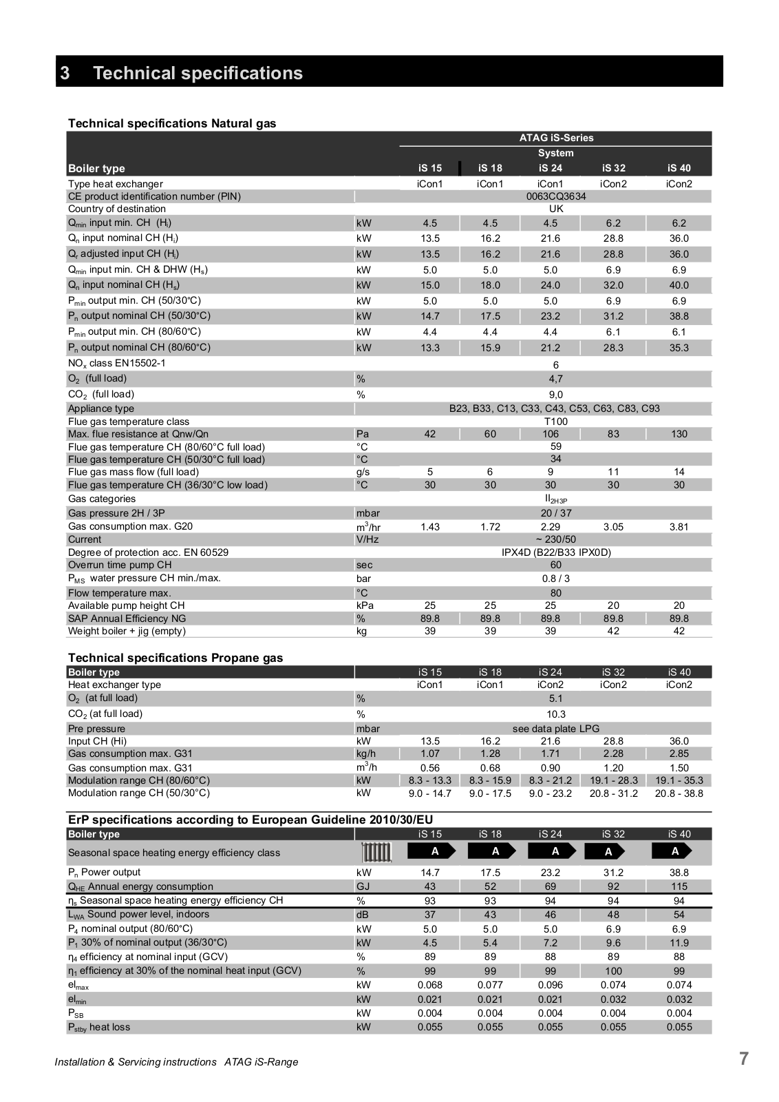


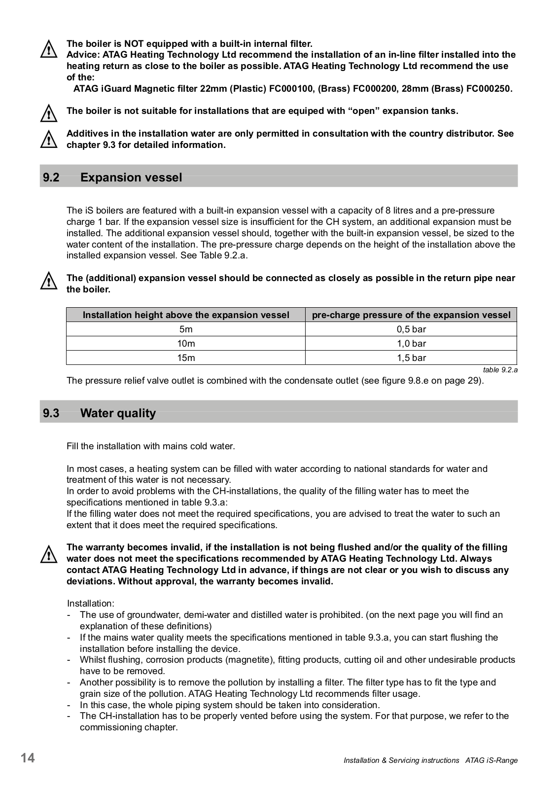


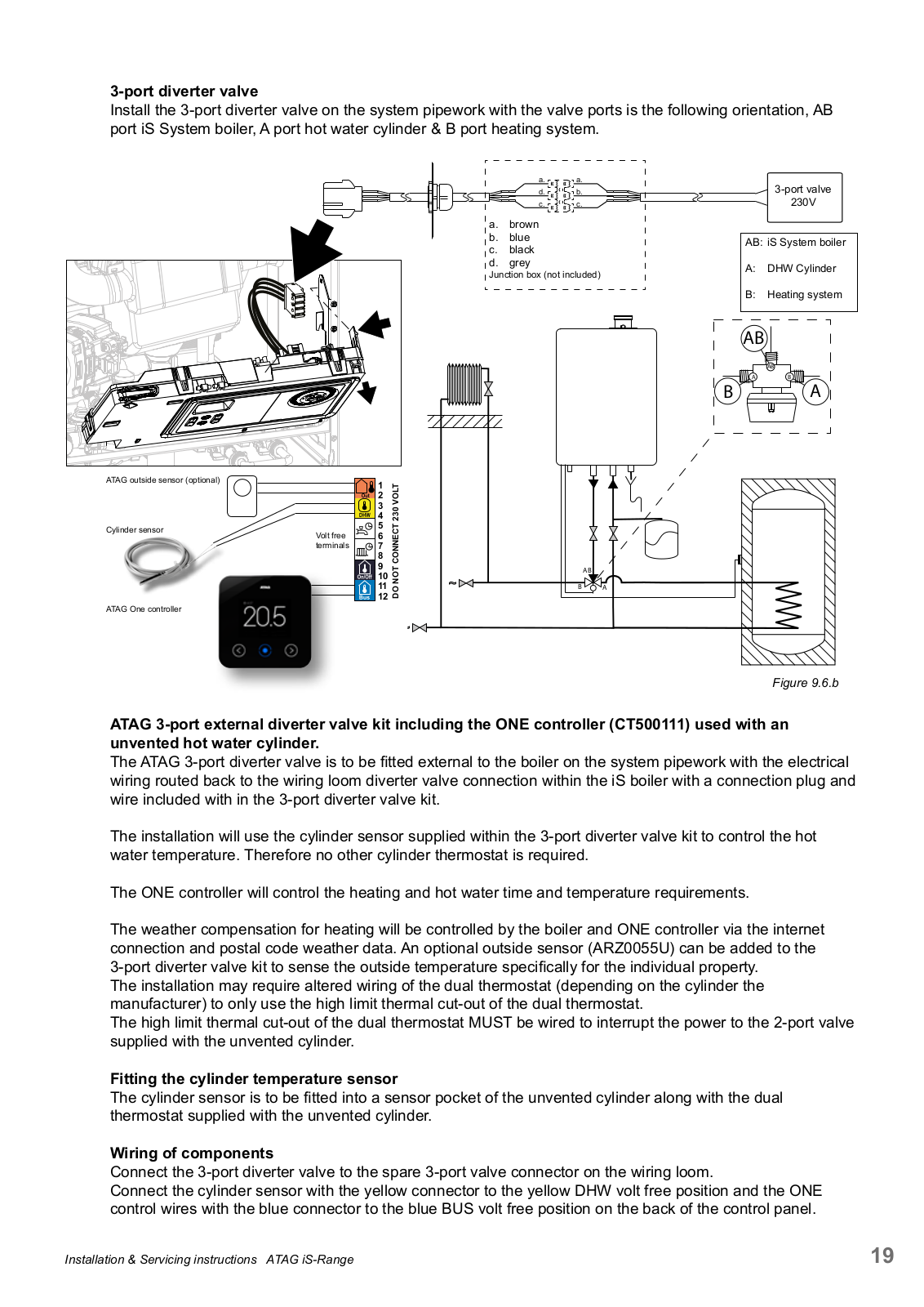

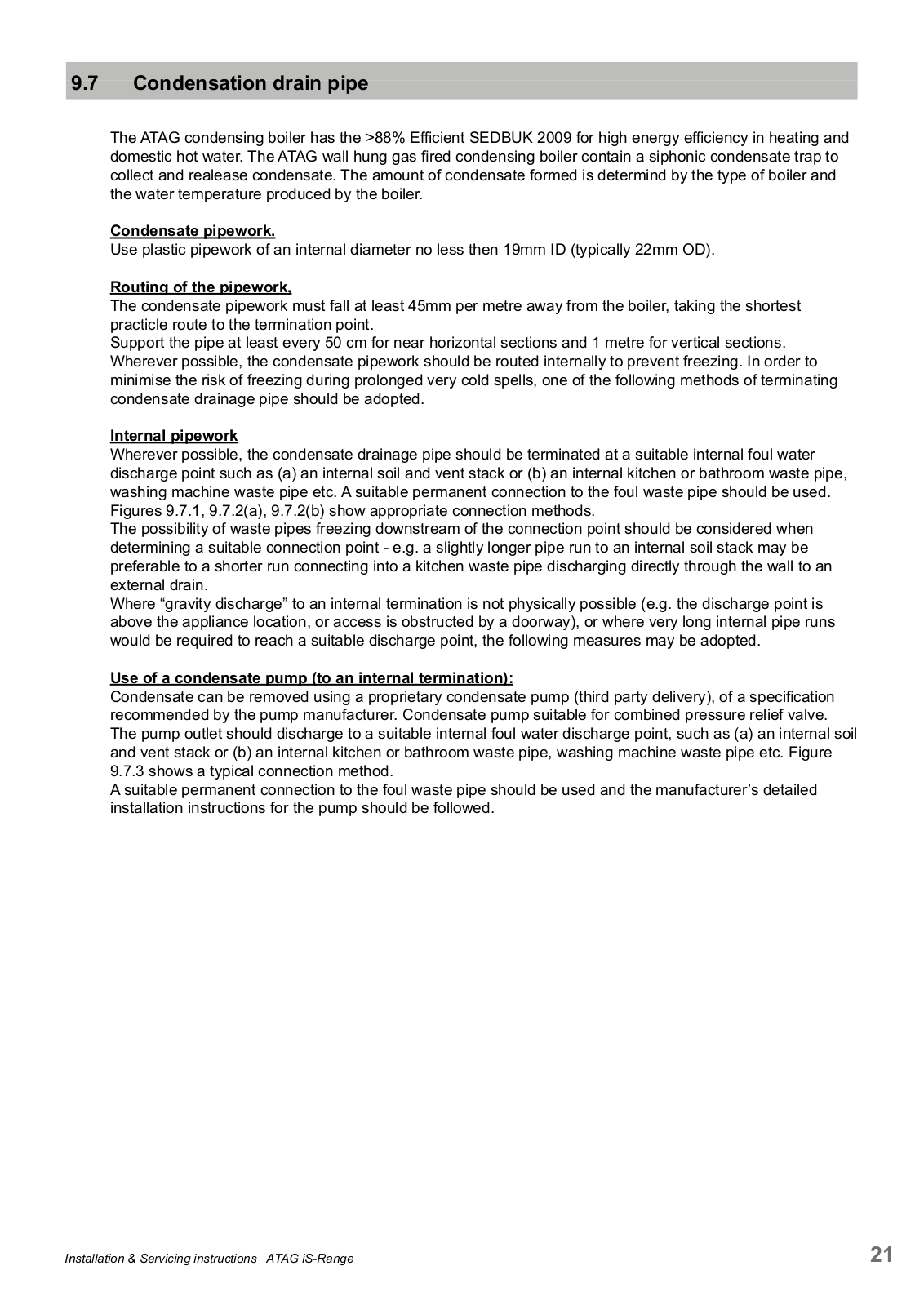


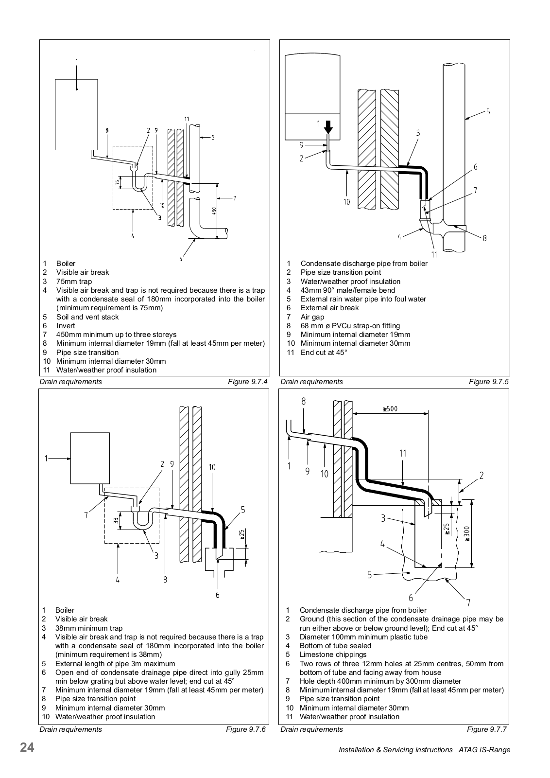

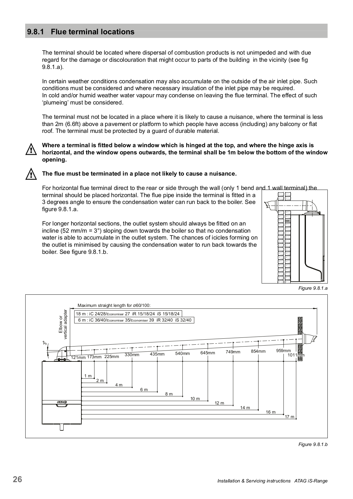

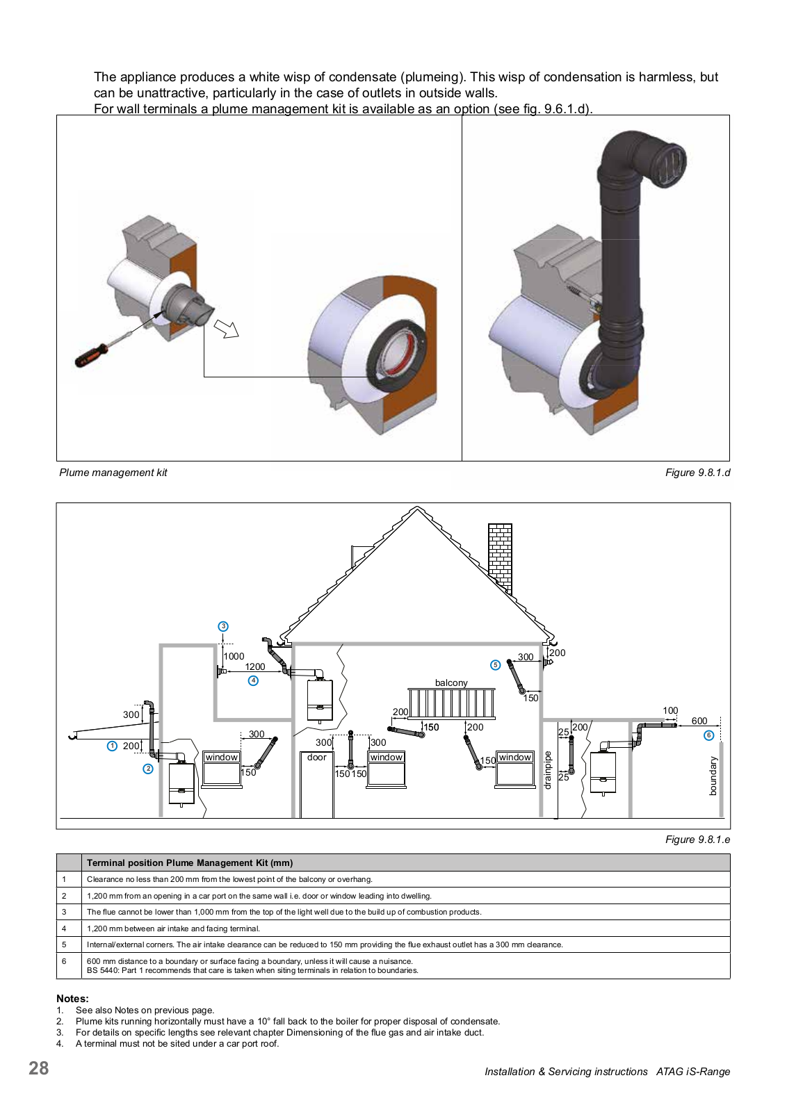


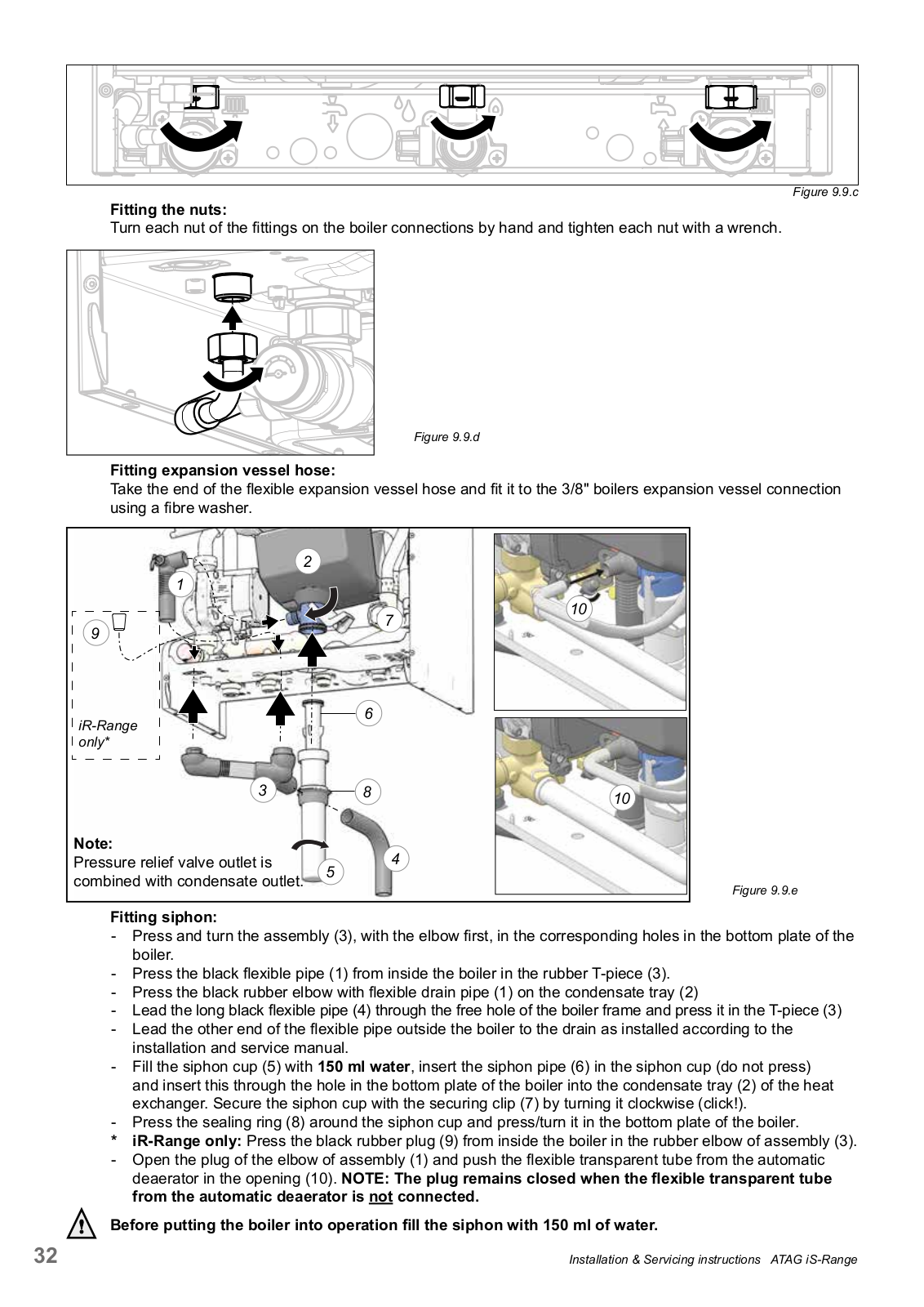
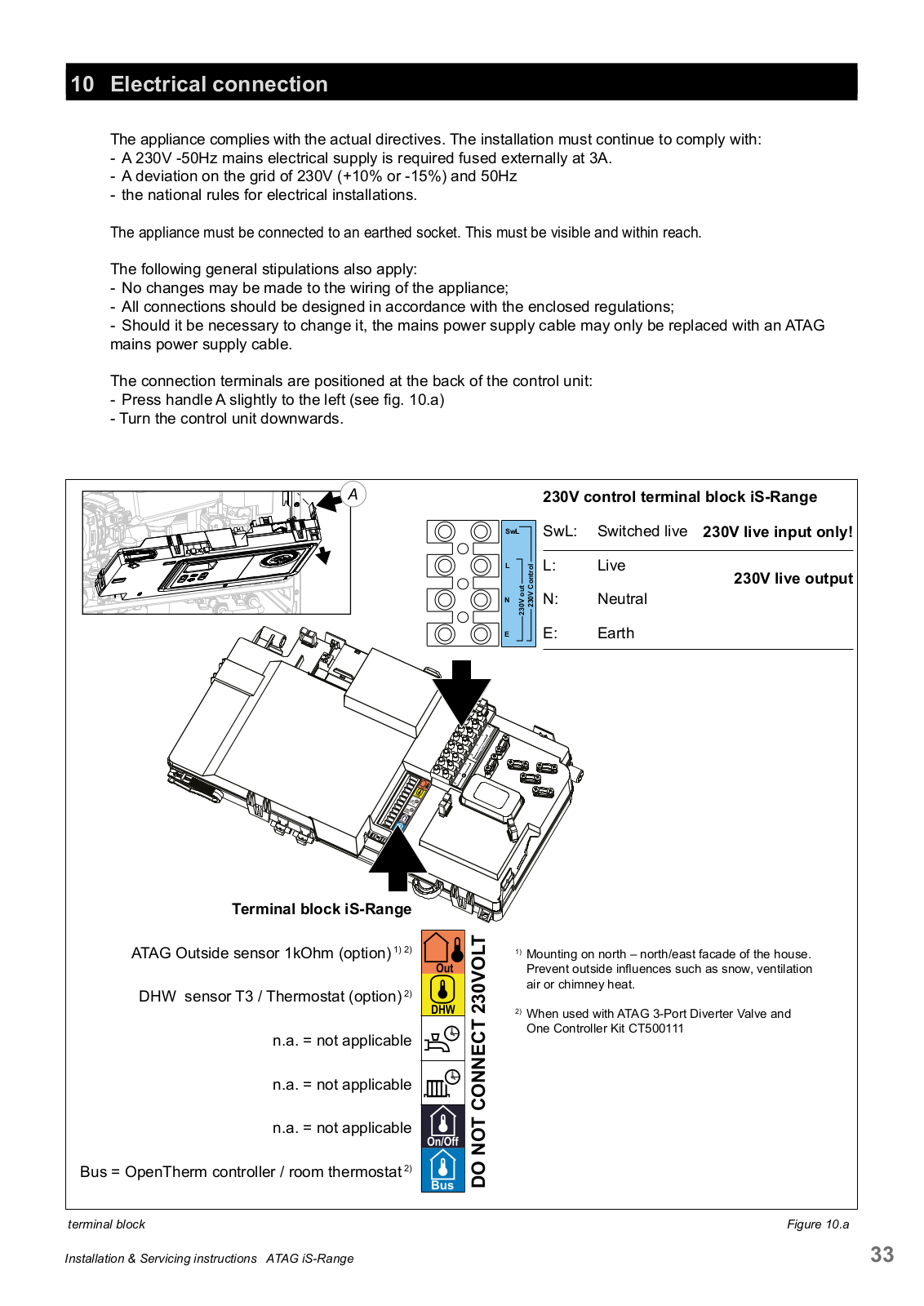


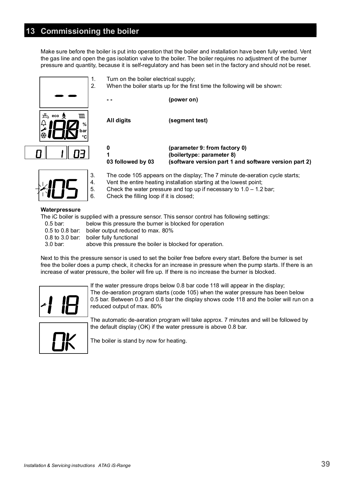

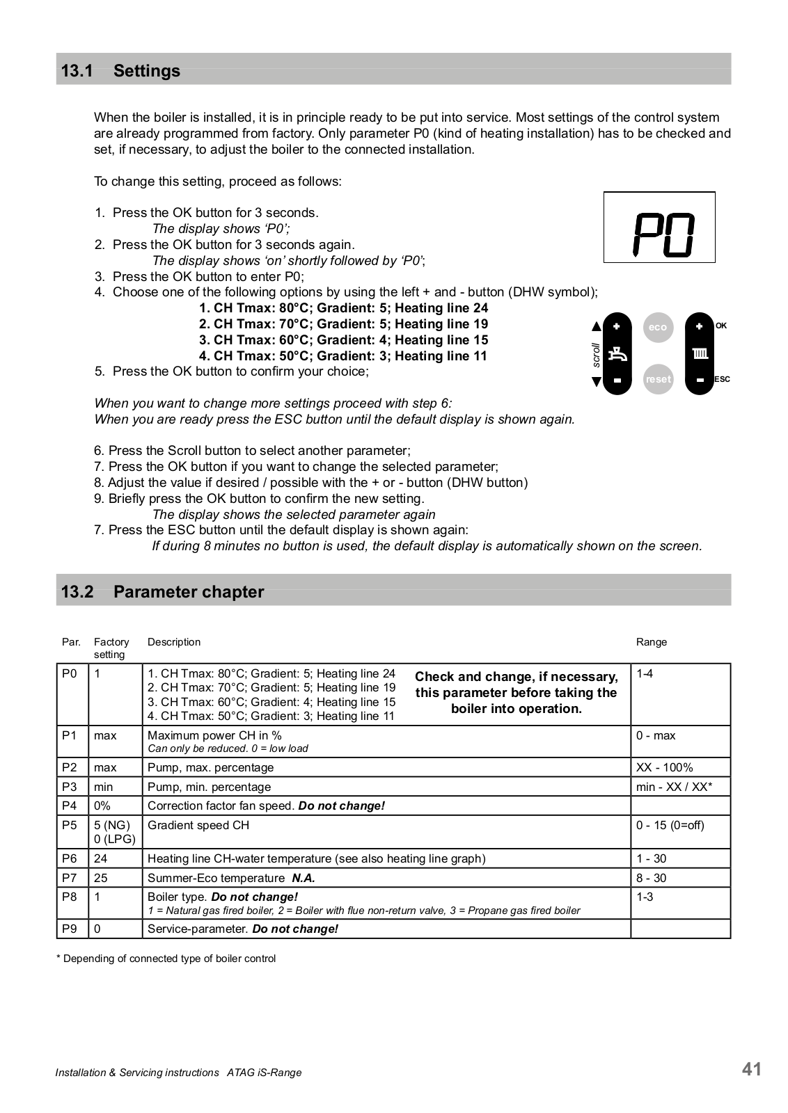


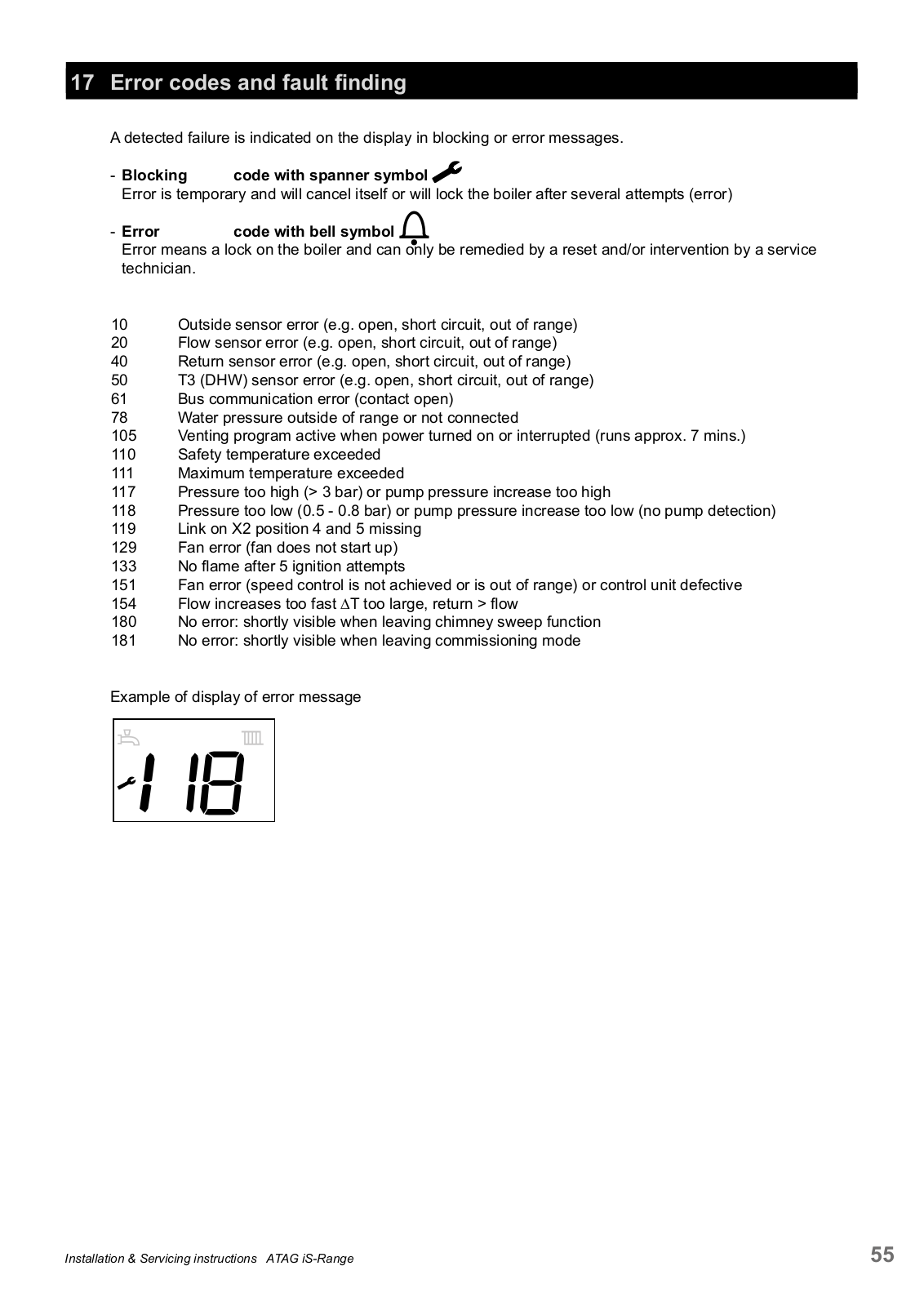


 Loading...