These instructions are to be retained by the user.
Selector Wheel | Turn the wheel left or right to scroll through available menu options | |
---|---|---|
OK button | Press to select/confirm an item | |
Ск | BACK button | Press to go back one screen |
)
Bet |
RESET button | Press to reset a fault code |
Commissioning
button |
Press
to enter into service mode which
allows adjustment of high fire/low fire and CO 2 settings ( Do not use. For service purposes only ) |
When the boiler is turned on, the main screen (also called the home screen) appears in the screen.
See chapter 12 for more information about button functions and read-out.
1 | Introdu | ction | 5 |
---|---|---|---|
2 | Rules & | Regulations (Symbols) | 6 |
3 | lechnic | al specifications | 8 |
4 | Dimens | 9 | |
6 | Boiler | 10 | |
7 | Boiler r | hoto components list | 11 |
8 | Mounti | ng boiler frame | 12 |
8.1 | Wall frame | 13 | |
9 | Connec | cting boiler | 14 |
9.1 | Open vent heating system | 14 | |
9.2 | Water quality | 15 | |
9.3 | Heating systems with plastic pipes | 16 | |
9.4 | 17 | ||
9.4.1 | Propage das connection (LPG) | 17 | |
943 | 18 | ||
9.4.4 | Dimensioning of the low pressure gas line | 18 | |
9.4.5 | De-aerating the LPG tank | 18 | |
9.5 | Condensation drain pipe | 19 | |
9.6 | Flue gas exhaust system | 23 | |
9.6.1 | Flue terminal locations | 24 | |
9.6.2 | Dimensioning of the flue gas and air intake duct | 27 | |
10 | 9.7 | Fitting the boiler onto the boiler frame. | 29 |
10 | al connection | 31 | |
10.1 |
32
32 |
||
10.2 | OnenTherm BUS & ON / OFF connection | 32 | |
10.4 | ATAG Zone connection | 32 | |
10.5 | Solar inlet sensor connection | 32 | |
10.6 | ATAG Outside sensor | 32 | |
10.7 | 230V Out (230V live output) | 32 | |
10.8 | 230V In (230V live input) | 32 | |
10.9 | 230V Control Block (230V live output) | 33 | |
10.10 | 230V Control Block (SwL Switched live) | 33 | |
10.11 | External pump (230V live oulput) | 33 | |
11 | Filling a | 34 | |
12 | Boiler o | 35 | |
12 | 12.1 | Change the Central Heating setpoint temperature | 37 |
12.2 | Change the language on the screen | 38 | |
12.3 | Change the time and date | 39 | |
12.4 | Change Units of Measurement | 40 | |
12.5 | Boiler information | 41 | |
10 | 12.6 | Pump function | 43 |
13 | Commi | ssioning the boiler | 44 |
13.1 | 40 | ||
1/ | Daram |
49
51 |
|
14 | 14 1 | Change the settings | 51 |
14.2 | Parameter listing | 52 | |
14.3 | Weather compensation | 54 | |
14.3.1 | Setting the weather compensation | 55 | |
15 | Routine | e servicing | 57 |
15.1 | Interim Service | 57 | |
15.2 | Full Service | 58 | |
15.3 | Component replacement | 62 | |
15.4
15 5 |
User's Instructions | 62 | |
16 |
10.0
Error of |
vvariarity |
02
62 |
10 | 16.1 | Reset a Fault code | 6/ |
16.2 | View Frror code History | 65 | |
10.2 | |||
Anne | ex A | System water additives | 66 |
Anne | ex B | Declaration of conformity | 67 |
Anne | ex C | Short parts list | 68 |
Work on the installation should only be carried out by qualified personnel with calibrated equipment and
These instructions describe the functioning, installation, use and primary maintenance of ATAG central heating boilers for the United Kingdom.
These instructions are intended for the use of Gas Safe registed installers in connection with the installation and putting into operation of ATAG boilers. It is advisable to read these instructions thoroughly, well in advance of installation. Separate instructions for use are supplied with the boiler for users of ATAG central heating boilers. ATAG is not liable for the consequences of mistakes or shortcomings which have found their way into the installation instructions or user's manual. Further, ATAG reserves the right to alter its products without prior notification.
Each boiler is fitted with an identification plate. Consult the details on this plate to verify whether the boiler is compliant with its intended location, e.g.: gas type, power source and exhaust classification.
On completion of the installation the installer or commissioning engineer must fill out and complete the Benchmark Commissioning Checklist found on page 70 of this manual and hand this to the customer for future record keeping. The Benchmark Service Record must also be completed by the service agent following each service call, and return to the customer.
The following regulations apply to installation of ATAG central heating boilers:
Gas Safety (Installation and Use). All gas appliances must by law, be installed by a competent person, eg. Members of Gas Safe Register and in accordance with the current Gas Safety Regulation. Failure to install appliance correctly could lead to prosecution.
All Gas Safe registered installers carry a Gas Safe ID card and have a registration number. You can call Gas Safe Register directly on 0800 408 5577.
In addition to the above regulations this appliance must be installed in compliance with the current IEE Regulations and Building Regulations. Regulations and bye laws of the Local Water Authority and the Current Health and Safety Regulation.
Benchmark places responsibilities on both manufacturers and installers. The purpose is to ensure that customers are provided with the correct equipment for their needs, that it is installed, commissioned and serviced in accordance
with the manufacturer's instructions by competent persons and that it meets the
requirements of the appropriate Building Regulations. The Benchmark Checklist can be used to demonstrate compliance with Building Regulations and should be provided to the customer for future reference.
Installers are required to carry out installation, commissioning and servicing work in accordance with the Benchmark Code of Practice which is available from the Heating and Hotwater Industry Council who manage and promote the Scheme.
Visit www.centralheating.co.uk for more information.
The current Electricity at Work Regulation must be complied with and also be in accordance with the relevant and current editions of the British Standards.
The ATAG iR boiler is a certified appliance and must not be modified or installed in any way contrary to this Installation Manual. Manufacturers instructions must not be taken, in any way, as overriding statutory obligations.
The ATAG iR boiler is a central heating boiler for "open" expansion tank systems (open vent) only. The boiler must be connected according to these instructions and all installation norms in respect of the part of the boiler to be connected.
The appliance is not to be used by children or persons with reduced physical, sensory or mental capabilities, or lack of experience and knowledge, unless they have been given supervision or instruction.
Observe the following rules of safety:
Carry out the following tasks in connection with maintenance, etc. to an already-installed boiler:
See chapter 15 and 16 for further instructions.
Take note of the following when maintenance or adjustments are needed:
- The boiler must be able to function during these activities; for this reason, the boiler's 230V power supply, gas pressure and water pressure must be maintained. Ensure that there is not a source of potential danger during these activities.
The following (safety) symbols may be encountered in these installation instructions and on the boiler (packaging):
Boiler must be stored away from frost.
Protect packaging and/or contents from damage as a result of insufficient care taken during transport.
Protect the boiler from weather conditions during transport and storage whilst still in its packaging.
The whole packaging is made of recycled materials and can be recycled again.
Transport and place the boiler in its packaging in this position.
Do not to step on or stand on the package.
An assembly or dismantling must be carried out.
Pay extra attention in connection with a particular operation.
Useful tip or advice
ATAG iR-Series | ||||||
---|---|---|---|---|---|---|
Boiler type | i15R | i18R | i24R | i32R | i40R | |
Type heat exchanger | iCon1 | iCon1 | iCon1 | iCon2 | iCon2 | |
CE product identification number (PIN) | 0063CQ3634 | |||||
Country of destination | UK | |||||
Q min input min. CH (Hi) | kW | 4.5 | 4.5 | 4.5 | 6.2 | 6.2 |
Q n input nominal CH (Hi) | kW | 13.5 | 16.2 | 21.6 | 28.8 | 36.0 |
Q r adjusted input CH (Hi) | kW | 13.5 | 16.2 | 21.6 | 28.8 | 36.0 |
Q min input min. CH (Hs) | kW | 5.0 | 5.0 | 5.0 | 6.9 | 6.9 |
Q n input nominal CH (Hs) | kW | 15.0 | 18.0 | 24.0 | 32.0 | 40.0 |
P min output min. CH (50/30°C) | kW | 5.0 | 5.0 | 5.0 | 6.9 | 6.9 |
P n output nominal CH (50/30°C) | kW | 14.7 | 17.5 | 23.2 | 31.2 | 38.8 |
P min output min. CH (80/60°C) | kW | 4.4 | 4.4 | 4.4 | 6.1 | 6.1 |
P n output nominal CH (80/60°C) | kW | 13.3 | 15.9 | 21.2 | 28.3 | 35.3 |
NO x class EN15502-1 | 6 | |||||
O 2 (full load) | % | 4.7 | ||||
CO 2 (full load) | d) % 9.0 | |||||
Appliance type | B23, B33, C | 13, C33, C43, C53, C6 | 63, C83, C93 | |||
Flue gas temperature class | T100 | |||||
Max. flue resistance at Qnw/Qn | Pa | 42 | 60 | 106 | 83 | 130 |
Flue gas temperature CH (80/60°C full load) | °C | 59 | ||||
Flue gas temperature CH (50/30°C full load) | °C | 34 | ||||
Flue gas mass flow (full load) | g/s | 5 | 6 | 9 | 11 | 14 |
Flue gas temperature CH (36/30°C low load) | °C | 30 | 30 | 30 | 30 | 30 |
Gas categories | II 2H3P | |||||
Gas pressure 2H / 3P | mbar | 20 / 37 | ||||
Gas consumption max. G20 | m3/hr | 1.43 | 1.72 | 2.29 | 3.05 | 3.81 |
Current | V/Hz | ~ 230/50 | ||||
Degree of protection acc. EN 60529 | I | PX4D (B22/B33 IPX0D | )) | |||
Overrun time pump CH | sec | 60 | ||||
Flow temperature max. | °C | 80 | ||||
SAP Annual Efficiency NG | % | 89.8 | 89.8 | 89.8 | 89.8 | 89.8 |
Weight boiler + jig (empty) | kg | 32 | 32 | 35 | 35 | 35 |
Technical specifications Propane (3P)
ATAG iR-Series | ||||||
---|---|---|---|---|---|---|
Boiler type | i15R | i18R | i24R | i32R | i40R | |
Type heat exchanger | iCon1 | iCon1 | iCon1 | iCon2 | iCon2 | |
O 2 (full load) | % | 5.1 | ||||
CO 2 (full load) | % | 10.3 | ||||
Pre pressure | mbar | 37 | ||||
Input CH (Hi) | kW | 13.5 | 16.2 | 21.6 | 28.8 | 36.0 |
Gas consumption max. G31 | kg/h | 0.96 | 1.15 | 1.54 | 2.05 | 2.56 |
Gas consumption max. G31 | m3/h | 0.51 | 0.61 | 0.81 | 1.08 | 1.35 |
Modulation range CH (80/60°C) | kW | 8.3 - 13.3 | 8.3 - 15.9 | 8.3 - 21.2 | 19.1 - 28.3 | 19.1 - 35.3 |
Modulation range CH (50/30°C) | kW | 9.0 - 14.7 | 9.0 - 17.5 | 9.0 - 23.2 | 20.8 - 31.2 | 20.8 - 38.8 |
ErP specifications according to European Guideline 2010/30/EU
Brand | ATAG | |||||
---|---|---|---|---|---|---|
Boiler type | i15R | i18R | i24R | i32R | i40R | |
Condensing boiler | yes | yes | yes | yes | yes | |
Combination heater | yes | yes | yes | yes | yes | |
Seasonal space heating energy efficiency class CH | A | А | А | А | А | |
P n Power output | kW | 13 | 16 | 21 | 28 | 35 |
Q HE Annual energy consumption | GJ | 43 | 52 | 69 | 92 | 115 |
η s Seasonal space heating energy efficiency CH | % | 94 | 94 | 94 | 94 | 94 |
L wa Sound power level, indoors | dB | 37 | 43 | 46 | 48 | 54 |
P 4 nominal output (80/60°C) | kW | 13 | 16 | 21 | 28 | 35 |
P 1 30% of nominal output (36/30°C) | kW | 4 | 5 | 7 | 10 | 12 |
η 4 efficiency at nominal input (GCV) | % | 89 | 89 | 88 | 89 | 88 |
η 1 efficiency at 30% of the nominal heat input (GCV) | % | 99 | 99 | 99 | 100 | 99 |
el max | kW | 0.023 | 0.028 | 0.036 | 0.040 | 0.046 |
el min | kW | 0.005 | 0.005 | 0.005 | 0.005 | 0.005 |
P sb | kW | 0.004 | 0.004 | 0.004 | 0.004 | 0.004 |
P stby heat loss | kW | 0.055 | 0.055 | 0.055 | 0.055 | 0.055 |
ATAG iR-Series | |||||||
---|---|---|---|---|---|---|---|
i15R | i18R | i24R | i32R | i40R | |||
Flue gas / Air intake A/B mm | 60/100 | ||||||
Gas connection | mm | 22 | |||||
CH Flow connection | mm | 22 | |||||
CH Return connection | mm | m 22 | |||||
Condensate drain connection ? mm | 21.5 |
The delivery package of the boiler is composed as follows:
The following components are not present in the boiler packaging as a standard and should be included in the installation according to the requirements:
The ATAG iR is a room sealed condensing and modulating CH boiler for "open" expansion tank systems (open vent).
This boiler can also be used on a sealed system with an external expansion vessel and 3 bar pressure relief valve.
The boiler is equipped with a compact stainless steel heat exchanger with smooth pipes. It is a well thoughtout principle using sustainable materials.
The boiler burns natural gas to supply heat (LPG conversion kits available). This heat is transferred in the heat exchanger to the water in the CH installation. The rapid cooling off of the flue gases causes condensation. This results in a very high efficiency. The condensate that is formed, has no negative impact on the heat exchanger and it's operation, and is removed through the internal siphon. This feature requires a condensate drain pipe connected to the drain of the building
The boiler is equipped with an intelligent control system. The boiler anticipates on the heat demand of the heating installation or hot water demand. This will cause the boiler to tune its capacity to the installation. This means that the boiler will function longer and at a low level.
( F The boiler has been tested according to valid CE standards and has a CE certificate and >88% Efficient SEDBUK 2009.
Statement: No banned materials including asbestos, mercury, CFC's have or will not be included in the product.
The installation location of the boiler has to be, and remain, frost-free. The boiler casing is splash water tight (IPX4D) and is suitable to be installed in e.g. a bathroom.
It is NOT necessary to have a purpose provided air vent in the room or internal space in which the boiler is installed. Neither is it necessary to ventilate a cupboard or compartment in which the boiler is installed, due to the extremely low surface temperature of the boiler casing during operation. Therefore the requirements of BS5440:2 may be disregarded.
The boiler can be mounted practically to any wall with the wall frame and the enclosed fixing equipment. The wall must be flat and of sufficient strength in order to be able to carry the boiler weight with its water content. Above the boiler there must be at least 210 mm working space in order to be able to fit a horizontal concentric flue system to the rear (See chapter 9.6 for more flue options). Make sure there is sufficient service space arround the boiler according figure 8.a. The location of the boiler can be determined by using the template.
The wall frame allows the possibity to pre-fit the complete heating system before fitting the boiler. Also the flue system can be prepared. Finally fitting of the flue system is done after fitting the boiler. See next page for all options for connection the heating, condensate, flue and gas installation.
Before hanging the boiler to the boiler frame remove the front panel of the boiler first. The front panel is also the air cabinet and is attached to the boiler case with 2 fasteners (A and B) (see figure 8.a).
Service dimensions (in mm)
See chapter 9.8 for further procedure to fit the boiler onto the boiler frame.
The boiler frame allows pipe work to be installed behind the boiler.
The pipe work must be installed at least 10mm inside the front of the frame.
ATAG i-Serie template and boiler frame
The boiler has the following connection pipes;
See following chapters for detailed information regarding each connection.
It is advisable to clean all of the boiler's connecting pipes and/or to power flush the installation before connecting it to the boiler.
/!\
This boiler is suitable for installations that have been equipped with "open" expansion tanks (open vent).
This boiler can also be used on a sealed system with an external expansion vessel and 3 bar pressure relief valve.
Open vent heating system 450 mm Recommended relationship Min height between pump cold feet and vent feed and рнм vant i m (Min. 1000 mm ΞĪ. Min Ē 2 Heating circuit Boile 150 mm Max
Connect the central heating system according to the current regulations.
Scheme open vent system
The boiler pipes can be connected to the installation by means of 22mm compression fittings. For connecting to thick-walled pipe (welded or fitted), adapters should be used.
Advice: ATAG Heating Technology Ltd recommend the installation of an in-line filter installed into the heating return as close to the boiler as possible. ATAG Heating Technology Ltd recommend the use of the:
ATAG iGuard Magnetic filter 22mm (Plastic) FC000100, (Brass) FC000200, 28mm (Brass) FC000250.
Additives in the installation water are only permitted in consultation with the country distributor. See chapter 9.2 for detailed information.
Fill the installation with mains cold water.
In most cases, a heating system can be filled with water according to national standards for water and treatment of this water is not necessary.
In order to avoid problems with the CH-installations, the quality of the filling water has to meet the specifications mentioned in table 9.2.a:
If the filling water does not meet the required specifications, you are advised to treat the water to such an extent that it does meet the required specifications.
The warranty becomes invalid, if the installation is not being flushed and/or the quality of the filling water does not meet the specifications recommended by ATAG Heating Technology Ltd. Always contact ATAG Heating Technology Ltd in advance, if things are not clear or you wish to discuss any deviations. Without approval, the warranty becomes invalid.
Installation:
Parameter | Value |
---|---|
Water type |
Potable water
Softened water |
рН | 6.0-8.5 |
Conductivity (at 20°C in µS/cm) | Max. 2500 |
Iron (ppm) | Max. 0.2 |
Hardness (°dH / ppm): | |
Installation volume/capacity
<20 l/kW |
1-12 °dH / 17-214 ppm |
Installation volume/capacity
>=20 l/kW |
1-7 °dH / 17-125 ppm |
Oxygen |
No oxygen diffusion allowed during operation.
Max. 5% filling water addition annually |
Corrosion inhibitors | Refer to Additives Attachment |
pH increasing or lowering agents | Refer to Additives Attachment |
Anti-freeze additives | Refer to Additives Attachment |
Other chemical additives | Refer to Additives Attachment |
Solid substances | Not allowed |
Residues of processing water not forming part of the drinking water | Not allowed |
able 9.2 a
Potable water: | Tap water compliant with the European drinking water guideline: |
98/83/EG dated 3 November 1998. | |
Softened water: | Water with partly de-ionised calcium and magnesium. |
Demi-water: | Virtually completely demineralised water (very low conductivity) |
Distilled water: | Water no longer containing minerals. |
When connecting or using an underfloor heating system, designed with plastic pipes, or plastic pipes are used elsewhere in the installation, one should ensure that the plastic pipes used comply with the DIN 4726/4729 standard. It is set out in this standard that the pipes may not have oxygen permeability higher than 0.1 g/m3.d at 40°C. If the system does not comply with this DIN standard, the underfloor heating component will have to be separated from the central heating appliance by means of a plate exchanger.
No recourse can be made to the terms of the warranty in the event of failure to observe the regulations pertaining to plastic underfloor heating pipes.
The local gas supplier should be consulted, at the installation planning stage, in order to establish the availability of an adequate supply of gas. An existing service pipe must NOT be used without prior consultation with the local gas supplier.
ATAG supplies boilers suitable for natural gas only and boilers for LPG only. Verify the identification plate on the boiler if the boiler is suitable for the gas kind on site. The boilers cannot be converted to another kind of gas.
Make sure that the gas pipe work does not contain dirt, particularly with new pipes.
The complete installation MUST be tested for gas tightness and purged as described in the above code.
The boiler connection is provided with an isolation valve with 22mm compression fitting, into which the gas line can be fitted.
Ensure that the pipework from the meter to the appliance is of adequate size. Do not use pipes of a smaller diameter than the boiler gas connection (22mm).
The gas supply must comply to the current Gas Safety, Installation & Use Regulations, in accordance with BS.6891.
The nominal inlet working gas pressure measured at the appliance should be 21 mbar +/- 2 mbar for Nat gas (G20). Allowing for the acceptable pressure loss of 1 mbar across the installation pipework, it can be assumed that a minimum permitted operating pressure of 18 mbar will be delivered to the inlet of the appliance. (Reference BS 6400-1 Clause 6.2 Pressure Absorption). When tested at the gas valve, the pressure drop from the meter to the gas valve must not be more than 4.0 mbar.
The LPG installation must comply to the current Gas Safety, Installation & Use Regulations, in accordance with BS:6891.
The tank must be provided with a high pressure regulator with a minimum capacity of 24 kg/h to reduce the tank pressure from 5 to 1.5 bar. The 1.5 bar high pressure gas line should have a minimum diameter of 15mm. In the high pressure gas line a house pressure regulator must be installed. When tested at the gas valve, the pressure drop from the pressure regulator to the gas valve must not be more than 2.5 mbar.
A
Each gas appliance which is connected to the propane installation must be provided with its own house pressure regulator. The house pressure regulator is a third party delivery.
The house pressure regulator must have a minimum capacity of 10 kg/h / 37 mbar and a CE certification.
ATAG advices to install the house pressure regulator as close as possible to the boiler. When placing the regulator inside, a discharge drain of ø6mm must be installed. The discharge drain must be directed outdoor. In case of a discharge the gasses will go outside.
If fitting the regulator outside the regulator should be protected against influences of the weather. The (de-) aeration must be positioned downwards (see figure 9.5.3.a).
ATAG advices to install measure points on all gas line parts to have the possibility to check for pressure loss.
Pre-pressure must be adjusted to 37 mbar by means of the house pressure regulator. The maximum permitted closing pressure may be 5 mbar higher than the maximum pre-pressure.
A too high closing pressure in the low pressure gas line can be caused by a high resistance or jam in this gas line. When the closing pressure keeps increasing the valve in the regulator is not closing correctly. In this case the regulator should be replaced.
The gas line from the house pressure regulator to the boiler must have the dimensions according the table below.
Boiler type | i15R | i18R | i24R | i32R | i40R |
---|---|---|---|---|---|
Diameter gas line | m | m | m | m | m |
ø15mm | - | - | - | - | - |
ø22mm | 18 | 18 | 18 | 18 | 18 |
ø28mm | 30 | 30 | 30 | 30 | 30 |
ATAG advices to inform the gas supplier that a central heating boiler is connected to the LPG tank. For the boiler it is absolutely necessary that the tank is free of air. When not the boiler will give ignition problems and will not function.
ATAG advices to measure the content of O2. This value should be lower than 1.3%. Contact the gas supplier in case of doubt.
The ATAG condensing boiler has the >88% Efficient SEDBUK 2009 for high energy efficiency in heating and domestic hot water. The ATAG wall hung gas fired condensing boiler contain a siphonic condensate trap to collect and realease condensate. The amount of condensate formed is determind by the type of boiler and the water temperature produced by the boiler.
Use plastic pipework of an internal diameter no less then 19mm ID (typically 22mm OD).
The condensate pipework must fall at least 45mm per metre away from the boiler, taking the shortest practicle route to the termination point.
Support the pipe at least every 50 cm for near horizontal sections and 1 metre for vertical sections. Wherever possible, the condensate pipework should be routed internally to prevent freezing. In order to minimise the risk of freezing during prolonged very cold spells, one of the following methods of terminating condensate drainage pipe should be adopted.
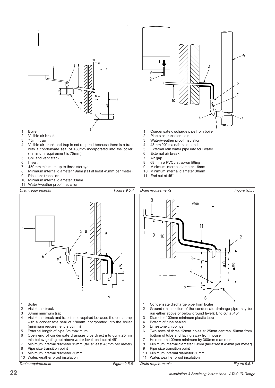
Wherever possible, the condensate drainage pipe should be terminated at a suitable internal foul water discharge point such as (a) an internal soil and vent stack or (b) an internal kitchen or bathroom waste pipe, washing machine waste pipe etc. A suitable permanent connection to the foul waste pipe should be used. Figures 9.5.1, 9.5.2(a), 9.5.2(b) show appropriate connection methods.
The possibility of waste pipes freezing downstream of the connection point should be considered when determining a suitable connection point - e.g. a slightly longer pipe run to an internal soil stack may be preferable to a shorter run connecting into a kitchen waste pipe discharging directly through the wall to an external drain.
Where "gravity discharge" to an internal termination is not physically possible (e.g. the discharge point is above the appliance location, or access is obstructed by a doorway), or where very long internal pipe runs would be required to reach a suitable discharge point, the following measures may be adopted.
Condensate can be removed using a proprietary condensate pump (third party delivery), of a specification recommended by the pump manufacturer.
The pump outlet should discharge to a suitable internal foul water discharge point, such as (a) an internal soil and vent stack or (b) an internal kitchen or bathroom waste pipe, washing machine waste pipe etc. Figure 9.5.3 shows a typical connection method.
A suitable permanent connection to the foul waste pipe should be used and the manufacturer's detailed installation instructions for the pump should be followed.
ain requirements
Figure 9.5.2 (b)
Drain requirem
The use of an externally-run condensate drainage pipe, terminating at a suitable foul water discharge point or purpose-designed soakaway, may be also be considered; however if this termination method is chosen then the following measures should be adopted
The customer/householder should be advised that even with the above measures this type of installation could freeze, and that if this were to occur then boiler shutdown could result, requiring remedial action - possibly involving a chargeable engineer call-out.
Where there are likely to be extremes of temperature or wind-chill, the use of a proprietary trace-heating system for external condensate drainage pipework, incorporating an external frost thermostat, should therefore be considered. If such a system is used then the installation instructions of the trace heating manufacturer and any specific recommendations regarding pipe diameter, insulation, etc. should be followed. All other relevant guidance on condensate drainage pipe installation should also be followed.
Other cold weather protection methods approved or endorsed by boiler manufacturers and/or service organisations may be adopted if these are considered suitable by the parties involved.
If an external soil/vent stack is used as the external termination then the connection method shown in Figure 9.5.4 should be used, together with the measures on insulation etc. as described above and shown in the diagram.
When a rain water downpipe is used as the termination (NB only permissible if this downpipe passes to a combined foul and rainwater drainage system) an air break must be installed between the condensate drainage pipe and the downpipe to avoid reverse flow of rainwater into the boiler should the downpipe itself become flooded or frozen. Figure 9.5.5 shows a suitable connection method.
Where the condensate drainage pipe is terminated over an open foul drain or gully, the pipe should terminate below the grating level, but above water level, in order to minimise "wind chill" at the open end. Pipe drainage will be improved if the end is cut at 45° as opposed to a straight cut. The use of a drain cover (such as those used to prevent blockage by leaves) may offer further protection from wind chill. Figure 9.5.6 shows a suitable connection method.
Where the condensate drain pipe terminates in a purpose-designed soakaway (see BS 6798:2014 or boiler installation manual for soakaway design requirements) any above-ground section of condensate drainage pipe should be run and insulated as described above. Figure 9.5.7 shows a suitable connection method.
Internal condensate drainage pipes run in unheated areas such as lofts, basements and garages should be treated as external pipe.
Draining of the condensation water to the external rain guttering is not permitted in view of the danger of freezing.
Before putting the boiler into operation fill the siphon with 150 ml of water.
Installation & Servicing instructions ATAG iR-Range
The flue gas exhaust system and air supply system consists of:
- Roof or wall terminal.
The flue gas exhaust system and air supply system must comply with:
The flue gas outlet and air supply installation must comply with the current regulation requirements in accordance with BS:5440 Part 1 and 2.
The appliance concentric connection diameter is 60/100 mm, to which the flue gas outlet and air supply system can be fitted, with or without elbow pieces. The maximum permissible pipe length is set out in Table 9.6.2.a.
For further information about the available components of the flue gas and air supply system we recommend you consult the Flue system literature. Combinations with other brands or systems are, without written permission from ATAG Heating, not permitted.
The ATAG flue gas system is meant, and designed, solely for the use on ATAG central heating boilers adjusted to Nat gas or LPG. For this purpose the CE Certificate has been supplemented under the Gastec nr: 0063CQ3634 The maximum flue gas temperatures are below 70°C (full load 80/60°C).
The proper operation may be adversely influenced by changes of or adjustments to the correct set up. Possible warranty claims will not be honoured if incorrect changes result in non compliance with the installation manual or local rules and regulations.
I
oom sealed syster
The terminal should be located where dispersal of combustion products is not unimpeded and with due regard for the damage or discolouration that might occur to parts of the building in the vicinity (see fig 9.6.1.c).
In certain weather conditions condensation may also accumulate on the outside of the air inlet pipe. Such conditions must be considered and where necessary insulation of the inlet pipe may be required. In cold and/or humid weather water vapour may condense on leaving the flue terminal. The effect of such 'plumeing' must be considered.
The terminal must not be located in a place where it is likely to cause a nuisance, where the terminal is less than 2m (6.6ft) above a pavement or platform to which people have access (including) any balcony or flat roof. The terminal must be protected by a guard of durable material.
Where a terminal is fitted below a window which is hinged at the top, and where the hinge axis is horizontal, and the window opens outwards, the terminal shall be 1m below the bottom of the window opening.
For horizontal flue terminal direct to the rear or side through the wall (only 1 bend and 1 wall terminal) the terminal should be placed horizontal. The flue pipe inside the terminal is fitted in a 3 degrees angle to ensure the condensation water can run back to the boiler. See figure 9.6.1.a.
For longer horizontal sections, the outlet system should always be fitted on an incline (52 mm/m = 3°) sloping down towards the boiler so that no condensation water is able to accumulate in the outlet system. The chances of icicles forming on the outlet is minimised by causing the condensation water to run back towards the boiler. See figure 9.6.1.b.
Figure 9.6.1.a
Figure 9.6.1.b
200 (000 11010 0) | ||
---|---|---|
D | Below balconies | 200 (See Note 3) |
Е | From a vertical drain pipe or soil pipe | 150 (See Note 3) |
F | From an internal or external corner | 300 (See Note 2) |
G | Above ground, roof or balcony level | 300 |
н | From a surface or boundary facing the terminal | 600 (See Note 4) |
I | From a terminal facing the terminal | 1200 |
J | Above an opening, air brick, window etc. | 300 (See Note 1) |
к | Vertically from a terminal on the same wall | 1500 |
L | Horizontally from a terminal on the same wall | 300 |
м | Horizontally from an opening, air brick, window etc. | 300 (See Note 1) |
Ν | Minimum protrusion through a roof | 300 |
0 | From a vertical obstruction | 300 |
Р | From an openable window | 600 |
Q | From an adjacent vertical terminal | 600 |
R | From an opening in the car port (e.g. door, window) into the dwelling | 1200 |
S | Below a roof window | 2000 |
Т | Terminal parallel to a boundary | 300 |
The appliance produces a white wisp of condensate (plumeing). This wisp of condensation is harmless, but can be unattractive, particularly in the case of outlets in outside walls. For wall terminals a plume management kit is available as an option (see fig. 9.6.1.d).
Plume management kit
Terminal position Plume Management Kit (mm) | |
---|---|
1 | Clearance no less than 200 mm from the lowest point of the balcony or overhang. |
2 | 1,200 mm from an opening in a car port on the same wall i.e. door or window leading into dwelling. |
3 | The flue cannot be lower than 1,000 mm from the top of the light well due to the build up of combustion products. |
4 | 1,200 mm between air intake and facing terminal. |
5 | Internal/external corners. The air intake clearance can be reduced to 150 mm providing the flue exhaust outlet has a 300 mm clearance. |
6 |
600 mm distance to a boundary or surface facing a boundary, unless it will cause a nuisance.
BS 5440: Part 1 recommends that care is taken when siting terminals in relation to boundaries. |
The total length of the run of the flue is determined by the flue diameter, including for the connection pipe, elbows fittings and terminal covers etc..
An incorrect dimensioned flue system can lead to disorders. Look at table 9.6.2.a for the choice of the boiler and the corresponding maximum equivalent flue length.
Explanation table 9.6.2.a:
maximum noted length L = distance between boiler (from elbow or vertical adapter) and the end of terminal
When using bends the noted value behind every bend should be deducted from the maximum straight length.
Concentric flue system ø60/100 (Horizontal & Vertical) | |||||||
---|---|---|---|---|---|---|---|
Туре | i15R | i18R | i24R | i32R | i40R | ||
Maximum equivalent length (L) | m | 15 | ç | 9 | |||
45° bend resistance length | m | -1.3 | -1 | .3 | |||
87° bend resistance length | m | -1.9 | -1 | .9 |
An i24R with a concentric flue gas system ø60/100mm has according to the table a maximum flue straight length of 15m In the system that is going to be put in there are 2 x 45° bends, so the maximum flue gas length is 15 – (2 x -1.3) = 12.4m.
Rear Flue L = wall thickness (B) + 150mm
Side Flue
L = wall thickness (B) + distance between boiler and wall (C) + 150mm
If the length L is more than 580mm rear flue or 585mm side flue, then a Horizontal flue fixed length 1000mm (60/100mm) with elbow (FA100205) will need to be used instead, up to 810mm.
Figure 9.6.2.b
Note : If it is required to cut an extension, DO NOT cut the end of the inner duct that incorporates the seal joint. Ensure the inner duct end without the seal joint is cut so that it is flush with the outer duct.
Ensure that all cuts are square and free from burrs.
Once assembled with the components pushed home, the flue is fully sealed.
Making good the wall with a sealing method such as sand and cement, or an air and watertight grommet seal such as FlueSnug is acceptable and local regulations should always be adhered to. If a grommet seal is to be used, ensure that each flue joint is screwed, and the flue is screwed to the flue elbow. A flue bracket should also be used at each section in accordance with the below guidance to provide stability to the flue. A combination of a grommet seal and making good the wall is also acceptable.
Note: The white of the flue can be on show or extended outside the dwelling wall as it is UV protected.
When mounting the flue gas system, pay attention to the flow direction (See figure 9.6.2.b). It is not permitted to mount a system upside down and will lead to complaints. Use the special grease (supplied in the accessory bag with the boiler) to simplify the fitting.
The ATAG flue system used is a push fit flue system, which does not require screws to be fitted at each flue joint, however this should be done if using a grommet to seal the flue on both sides of the wall to ensure the flue is secured. The flue system must be adequately supported at regular intervals between brackets of no more than 1.0 metres for horizontal sections and no more than 2.0 metres for vertical sections.
After the pipe work of gas, heating installation installation has been fitted to the boiler frame, the boiler can be placed on the boilerframe
Before hanging the boiler to the boiler frame remove first the cover of the boiler first. The cover is also the air cabinet and is attached to the boiler case with 2 fasteners (A and B) (see figure 8.a).
Note that there is an earth cable (when present) to disconnect when removing the cover from the boiler. Free space for removing the connector is 400mm. Remember to connect this earth cable (when present) when replacing the cover.
Always refit and turn the 2 screws tight in the fasteners A and B after replacing the cover.
Remove furthermore the 4 plastic caps from the boiler connections.
When removing the plastic sealing caps from the pipes, contaminated testing water may be released.
Figure 97 a
3 and 4. Take the boiler and hang it from approx. 50mm higher than the boiler frame vertical downwards on the boiler frame so the fittings will be axial approached.
Turn each nut of the fittings on the boiler connections by hand and tighten each nut with a wrench.
Figure 9.7.d
Before putting the boiler into operation fill the siphon with 150 ml of water.
The appliance complies with the actual directives. The installation must continue to comply with:
The appliance must be connected to an earthed socket. This must be visible and within reach.
The following general stipulations also apply:
This connection comes with a loop of wire. This loop enables the boiler to work. Removing the loop will stop the boiler from firing up.
The connection can be used to connect a condensate pump safety overflow switch, where this will stop the boiler from firing if the condensate pump cannot get rid of the condensate water and the safety overflow switch is triggered
N/A not applicable.
This PCB will detect if an OpenTherm or an On / Off device is connected to the blue plug on the terminal block.
An OpenTherm compatible device as well as a volt free on / off thermostat or programmable room thermostat can be used to switch on or off the heat demand to the boiler.
The ATAG One zone smart room thermostat is the primary candidate for use of the ATAG zone eBus connection. The smart room thermostat can also be substituted by another ATAG zone compatible room controller, this eBus enables the boiler to modulate set point temperatures for optimal efficiency. On top of the thermostats, the connection is used for other ATAG zone compatible devices such as zone management accessories.
N/A not applicable.
When a weather compensation sensor (supplied with the boiler) is used, the two wires from the outside sensor get wired into the plug supplied on the terminal block in the rose connector position.
Not used.
This is the 230V mains power input to the boiler connection.
f a live, neutral or earth wire is required for an external clock/programmer these can be taken from the (L) live, (N) Neutral or (E) earth 230V live output aqua blue connections on the 230v control terminal block. If an external 230V clock/programmer is used, then a switched live is required from the control(s) to connect to the 230V control aqua blue connector in position (SwL) Switched live to fire up the boiler.
If a 230V room thermostat is used, then a switched live is required from the control(s) to connect to the 230V control aqua blue connector in position (SwL) Switched live to fire up the boiler. This could be in series after the clock/ programmer to the room stat, then to SwL on the 230V control aqua blue connector.
The system pump MUST be wired directly back to the boiler into the (L) live pump, (N) Neutral pump and (E) earth pump 230V live output to pump connections on the 230V control terminal block. This is so the boiler can control when the pump is operated. This will allow the boiler to run the pump for the pump overrun feature, which will last 60 seconds.
The central heating installation needs to be filled with potable water according to the requirements in chapter 9.3 'Water quality'. For filling the CH installation, use the the feed and expansion header tank. Use the following procedure:
1 | Ensure all system and boiler drain points are closed; |
---|---|
2 | Open all isolation and motorised valves; |
3 | Turn on the water supply to the system header tank |
4 | Vent all radiators and pipework; |
5 | Check system for any visable leaks; |
When powering up the boiler (described in chapter 13) an automatic air purge program will run to vent the boiler.
Before the electrical power is switched on, it helps to know the operation of the boiler in advance. On this page the controls are described in short. The next page describes the button functions and the symbols on the screen.
Resistance ta | ble sensors | ATAG iC-, iS- an | d iR-series |
---|---|---|---|
Outside senso | r T4 | Flow sensor T1 | |
Return sensor T | 2 | ||
DHW sensor T3 | |||
NTC1k (25°C) | NTC10k (25°C) | ||
Temperature | Resistance | Temperature | Resistance |
[°C] | [Ohm] | [°C] | [Ohm] |
-10 | 4.574 | -10 | 55.047 |
-9 | 4.358 | 0 | 32.555 |
-8 | 4.152 | 10 | 19.873 |
-7 | 3.958 | 12 | 18.069 |
-6 | 3.774 | 14 | 16.447 |
-5 | 3.600 | 16 | 14.988 |
-4 | 3.435 | 18 | 13.674 |
-3 | 3.279 | 20 | 12.488 |
-2 | 3.131 | 22 | 11.417 |
-1 | 2.990 | 24 | 10.449 |
0 | 2.857 | 26 | 9.573 |
1 | 2.730 | 28 | 8.779 |
2 | 2.610 | 30 | 8.059 |
3 | 2.496 | 32 | 7.406 |
4 | 2.387 | 34 | 6.811 |
5 | 2.284 | 36 | 6.271 |
6 | 2.186 | 38 | 5.779 |
7 | 2.093 | 40 | 5.330 |
8 | 2.004 | 42 | 4.921 |
9 | 1.920 | 44 | 4.547 |
10 | 1.840 | 46 | 4.205 |
11 | 1.763 | 48 | 3.892 |
12 | 1.690 | 50 | 3.605 |
13 | 1.621 | 52 | 3.343 |
14 | 1.555 | 54 | 3.102 |
15 | 1.492 | 56 | 2.880 |
16 | 1.433 | 58 | 2.677 |
17 | 1.375 | 60 | 2.490 |
18 | 1.320 | 62 | 2.318 |
19 | 1.268 | 64 | 2.159 |
20 | 1.218 | 66 | 2.013 |
21 | 1.170 | 68 | 1.878 |
22 | 1.125 | 70 | 1.753 |
23 | 1.081 | 72 | 1.638 |
24 | 1.040 | 74 | 1.531 |
25 | 1.000 | 76 | 1.433 |
26 | 962 | 78 | 1.341 |
27 | 926 | 80 | 1.256 |
28 | 892 | 82 | 1.178 |
29 | 858 | 84 | 1.105 |
30 | 827 | 86 | 1.037 |
35 | 687 | 88 | 974 |
40 | 575 | 00 | 015 |
The boiler is equipped with self-managing control system. This control system takes over a large part of the manual settings, which simplifies the start-up of the installation considerably.
After filling the installation and switching on the electrical power supply a short start-up program is activated. This shows all digits, boiler type and software version and the automatic air purge program is activated. The automatic air purge program lasts for approx. 7 minutes and stops automatically. Then the boiler will switch on for the enabled program.
With a demand from the heating controls, the boiler activates its 1 minute delay period. This is to prevent the heat exchanger from losing its heat too quickly in the event of a hot water demand. Then the pump starts and after 30 seconds the gradient control becomes active. The starting point of the gradient control is the currently existing flow temperature. A Delta-T control (25K) ensures a stable control according to heat request.
If the flow temperature is below the T-set value of 20°C the boiler will immediately start.
If during a demand from the heating the burner switches off, because the desired flow temperature is exceeded, there will be an anti-cycle time in operation for 5 minutes. This means that the burner switches on again after 5 minutes if there is still a demand from the heating.
The ATAG iR is equipped with boiler sensors of 10kOhm. The resistance value and corresponding temperature are shown in the accompanying table.
able 12.a
1. | Selector Wheel | Turn the wheel left or right to scroll through available menu options |
---|---|---|
2. | OK button | Press to select/confirm an item |
3. | BACK button | Press to go back one screen |
4. | RESET button | Press to reset a fault code |
5. |
Commissioning
button |
Press
to enter into service mode which
allows adjustment of high fire/low fire and CO 2 settings ( Do not use. For service purposes only ) |
The Control unit has a 'sleep mode' if no key is operated within a certain time. Activation occurs by any key operation.
Outdoor temperature (if connected)
Ľ, | ר |
---|---|
FCO
DHW status symbol. A box around the tap symbol indicates DHW is in operation
Central heating status symbol. A box around the radiator symbol indicates central heating is in operation
ECO Hot water is not preheated COMFORT Hot water is pre-heated and kept hot
O 25/07/18 09:00 ※ ▲ 19° ▲ 1.5 bar 80° COMFORT AUTO 100 Press OK to enter Menu 100 100 BACK O 000 000 RESET 110 110 | 1 | From the controller Home screen, press OK . |
---|---|---|
|
2 |
Turn the selector wheel to highlight
Complete Menu
.
Press OK . |
CH Settings DHW Settings Screen Settings | 3 |
CH Settings
is highlighted.
Press OK . |
CH Setpoint Temp
Time program Holiday function AUTO function Pump continuous running |
4 |
Option
CH Setpoint Temp
is highlighted.
Press OK . |
T set Z1 80
T set Z2 80 T set Z3 80 |
5 |
Option
T set Z1
is highlighted.
Press OK . Note: T set Z2 and T set Z3 are inactive functions. |
T set Z1
Set the send temperature of zone 1 80°C Press OK to confirm |
7 |
Turn the selector wheel until the desired temperature appears on the screen.
Press OK . Available temperature settings: 20°C - 80°C |
To gain access to the Boiler information, proceed as follows:
The Boiler information is accessable through a code.
A list of the most common Boiler information can be found in the table below
8.2.2 | Fan Speed in Rpm |
---|---|
8.2.8 | Gas Power in kW |
8.2.9 | Heating circuit pressure in bar = '' |
8.3.0 | CH Flow Set T in °C |
8.3.1 | CH Flow T in °C |
8.3.2 | CH Return T in °C |
8.3.5 | Outdoor T (only if an outside sensor is connected) in °C |
8.7.5 | Ionization current in µA |
By default the boiler is set in such a manner that the pump will switch on in case of a heat request for CH or DHW. Switching on and off is managed entirely by the control system.
If there is danger of frost damage to the CH installation, it is advisable to let the pump run continuously, proceed as follows:
If the (T1) flow sensor registers a temperature of 5°C or below in the boiler, the boiler will fire up. The boiler keeps on firing until the temperature reaches 10°C (measured on the flow sensor) and the boiler switches off again.
Make sure before the boiler is put into operation that the boiler and installation have been fully vented. Vent the gas line and open the gas isolation valve to the boiler. The boiler requires no adjustment of the burner pressure and quantity, because it is self-regulatory and has been set in the factory and should not be reset.
Device discovery | |
---|---|
14.09.18 | |
Initializing | |
14.09.18 | |
Airpurge active | |
⊞ |
The automatic air purge program will take approx. 7 minutes and will be followed by the home screen.
The iR boilers are supplied with a flow switch. If the external pump starts, the flow switch is made, the burner is set free, if the flow switch is not made the boiler will not fire.
Work on the installation and/or boiler should only be carried out by qualified personnel with calibrated equipment.
At the time of commissioning, complete all revelant sections of the Benchmark Checklist located on At the line of commission, ..., the inside back pages of the document.
For maintenance of the boiler the cover has to be removed. Unscrew the 2 locking screws from the fasteners at the top of the boiler, unlock the fasteners and remove the cover in a forward motion. See figure 16.a
Changing settings, such as the burner pressure and the amount of air flow, is superfluous. Only in case of a failure or when replacing the gas block, venturi and/or fan, the CO, percentage should be checked.
Close the relevant commissioning valves during the maintenance activities. See figure 15.a.
The heating installation must be provided with a fill and drain valve. Use this feature also for draining the boiler.
Figure 15.a
The CO, check consists of 2 steps or, if necessary, 3 steps:
Step 1:Check on full loadStep 2:Check on low loadStep 3:Adjustment (if necessary).
The CO2 setting is preset at the factory on all boilers. A calibrated Flue Gas Analyser must be carried out during commissioning.
- Ensure that the boiler is in operation and that the heat, which it produces, can be discharged.
You can set the full load of the boiler as follows:
Measuring point CO, Figure 15.1.a
The boiler will switch to maximum power output of the boiler: the screen shows 100% (heating capacity)
After this check has been done at full load, the CO2 value at low load need to be tested (see Step 2 on page 47). If there are any deviations in the result, then these must be corrected (see Step 3 on page 48).
CO 2 check on full load (Step 1) | |||||
---|---|---|---|---|---|
Full load | Natural gas (G20) | Propane (G31)* | |||
00 | Nominal 9.0% | Nominal 10.3% | |||
CO 2 Nominal 9.0% Minimum 8.6%, maximum 9.6% | Minimum 9.9%, maximum 11.0% |
Values are valid with closed cover/air box.
* Only possible if LPG conversion kit is installed!
The low load of the boiler can be set by you as follows:
Measuring point CO2 Figure 15.1.a
The boiler will switch to minimum power output (low load) of the boiler;
the screen shows 0% (heating capacity).
The CO2 value at low load must be lower than the CO2 value at full load. The measuring procedure must be carried out, until a constant value is achieved. Please contact ATAG, if the values should lie outside of the applicable tolerances.
- Press the back button for 5 seconds to exit chimney sweep mode.
This completes the procedure.
The maximum duration of the commissioning function, without interruption, is 20 minutes.
CO 2 check on low load (Step 2) | ||||||
---|---|---|---|---|---|---|
Low load | Natural | gas (G20) | Propan | e (G31)* | ||
Full load recorded | Accepted low range | Full load recorded | Accepted low range | |||
9.6% | 9.3% - 7.5% | 11.0% | 10.9% - 8.9% | |||
9.5% | 9.2% - 7.5% | 10.9% | 10.8% - 8.9% | |||
9.4% | 9.1% - 7.5% | 10.8% | 10.7% - 8.9% | |||
9.3% | 9.0% - 7.5% | 10.7% | 10.6% - 8.9% | |||
9.2% | 8.9% - 7.5% | 10.6% | 10.5% - 8.9% | |||
CO 2 Example readings | 9.1% | 8.8% - 7.5% | 10.5% | 10.4% - 8.9% | ||
9.0% | 8.7% - 7.5% | 10.4% | 10.3% - 8.9% | |||
8.9% | 8.6% - 7.5% | 10.3% | 10.2% - 8.9% | |||
8.8% | 8.5% - 7.5% | 10.2% | 10.1% - 8.9% | |||
8.7% | 8.4% - 7.5% | 10.1% | 10.0% - 8.9% | |||
8.6% | 8.3% - 7.5% | 10.0% | 9.9% - 8.9% | |||
9.9% | 9.8% - 8.9% |
Values are valid with closed cover/air box
* Only possible if LPG conversion kit is installed!
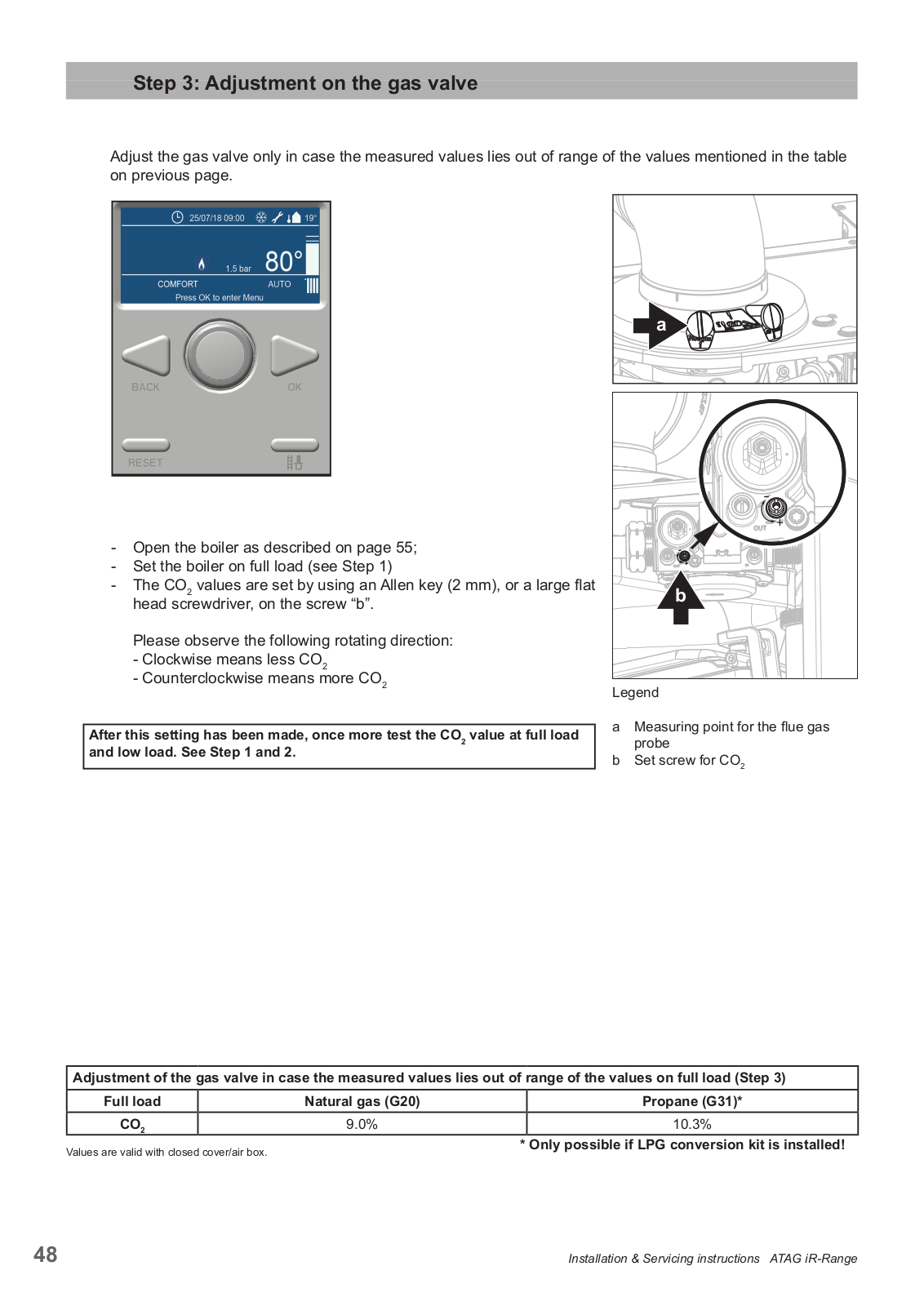
Adjust the gas value only in case the measured values lies out of range of the values mentioned in the table on previous page.
Please observe the following rotating direction:
After this setting has been made, once more test the CO2 value at full load and low load. See Step 1 and 2.
Leaend
Adjustment of the gas valve in case the measured values lies out of range of the values on full load (Step 3) | ||||
---|---|---|---|---|
Full load | Propane (G31)* | |||
CO 2 | 9.0% | 10.3% |
Values are valid with closed cover/air box.
* Only possible if LPG conversion kit is installed!
NOTE: The air gas ratio valve is factory set and must not be adjusted during commissioning unless this action is recommended following contact with the manufacturer.
If any such adjustment is recommended and further checking of the boiler is required the installer/service engineer must be competent to carry out this work and to use the flue gas analyser accordingly.
If the boiler requires conversion to operate with a different gas family (e.g. conversion from natural gas to LPG) separate guidance will be provided by the boiler manufacturer
The boiler manufacturer's installation instructions should have been followed, gas type verified and gas supply pressure/rate checked as required prior to commissioning.
As part of the installation process, especially where a flue has been fitted by persons other than the boiler installer , visually check the integrity of the whole flue system to confirm that all components are correctly assembled, fixed and supported. Check that manufacturer's max. flue lengths have not been exceeded and all guidance has been followed (e.g. Gas Safe Technical Bulletin TB008 where chimney/flues are in voids).
The Flue Gas Analyser should be of the correct type, as specified by BS 7967
Prior to its use, the flue gas analyser should have been maintained and calibrated as specified by the manufacturer. The installer must have the relevant competence for use of the analyser.
Check and zero the analyser IN FRESH AIR as per analyser manufacturer's instructions. Key:
CO = carbon monoxide CO 2 = carbon dioxide O 2 = oxygen ppm = parts per million Combustion ratio = The CO reading measured in ppm divided by the CO2 reading first converted to ppm GU(I&U)R = Gas safety (Installation & use) Regulation.
When the boiler is installed, it is in principle ready to be put into service. Most settings of the control system are already programmed from factory.
To change this setting, proceed as follows:
The settings are accessable through a code.
Menu | ||
---|---|---|
0 | Network | |
1 | < Not Available > | |
2 | Boiler Parameters | |
3 | < Not Available > | |
4 | Zone1 Parameters | |
From the controller Home screen, press the BACK and OK buttons at the same time for 7 seconds.
Turn the selector wheel to highlight 007 as the Technical Code. Press Save
The screen left appears.
Turn the selector wheel to highlight Complete Menu . Press OK . It takes a while to load the Menu
The screen left appears.
This way you have access to the complete parameter level.
In the table below you will find a complete overview of all available Parameters
Parameters in I-series boiler | |||||||
---|---|---|---|---|---|---|---|
Chapter | Parameter number | Name | Describtion | Unit | Range | Default | |
2 | Boiler Parameters | ||||||
2.0 | General | ||||||
2.0.0 | DHW Set point | Water set point temperature in DHW mode during comfort periods | °C | 40-65 (Combi) | 60 | ||
202 | Cas Turne | 0 - Nat Cas | 40-65 (combi) | 60 | |||
2.0.2 | Gas Type | 0.2 | U | ||||
2 = 6230 | 0-2 | ||||||
2.0.3 | Maximum water temp | maximum absolute water temperature | °C | 80-90 | 80 | ||
2.0.4 | Altitude | parameter for altitude compensation | m | 0-7000 | 0 | ||
2.0.5 | Fan inc. Percentage | percentage of fan speed increase when reaching ionisation threshold | % | 0 - 25 | Do Not Change | ||
2.0.6 | T-Gradient | Gradient Function | °C/min | 0-15 | 5 | ||
2.1 | Free | ||||||
2.1.7 | pump continious running | 0 = Disabled | 0-1 | 0 | |||
1 = Enabled | |||||||
2.1.8 | Pomp mode max DHW | Max pump speed during DHW burning cycle | % | pump mode min - 100% | 90 | ||
2.2 | Settings | ||||||
2.2.4 | Thermoregulation | Thermoregulation function enable 0 = OFF 1 = ON | 0 - 1 | 1 | |||
2.2.7 | Boiler Hybrid | Used to set the boiler as a part of a hybrid system | 0 - 1 | 0 | |||
2.2.0 | Deilen Manzien | (Energy manager presence detaction ) | 0.2 | 0 | |||
2.2.8 | Boiler Version | Type of boller selection | 0 - 2 | 0 | |||
U = COMBI | |||||||
2 - Storage with Thermostat | |||||||
23 | Central Heating -1 | ||||||
2.5 | 2 3 1 | Max CH Adjustable | CH nower level adjustable by engineer to the level required | % | 0 - 100 | 100 | |
21012 | by the building | ,,, | 0 100 | 100 | |||
2.3.7 | CH pump overrun | CH post circulation time | Min | 0 - 16 | 1 | ||
2.4 | Central Heating - 2 | ||||||
2.4.5 | Max pump Modulation | Maximum pump speed in CH mode | % | min - 100 | 95 | ||
2.4.6 | Min pump Modulation | Minimum pump speed in CH mode | % | 25 - Max | 50 | ||
2.4.9 | External Temp correction | Offset of the Outdoor temperature reading | °C | -3 - +3 | 0 | ||
2.5 | Domestic Hot Water | ||||||
2.5.0 | Comfort function | DHW pre-heating or storage heating operation mode seletion | 0 - 2 | 0 | |||
0 = Disabled | |||||||
1 = Time Based | |||||||
2.0 | Dailor monuel cottings | 2 = Always active | |||||
2.0 | Manual mode activation | to onable or disable manual mode 0 = OEE 1 = ON | 0 1 | 0 | |||
2.6.0 | Rump Control | 0-1 | 0 | ||||
2,6.2 | Fan Control | 0 = OFF 1 = ON | 0 - 1 | 0 | |||
2.6.3 | Diverter valve control | 0 = OFF 1 = ON | 0 - 1 | 0 | |||
2.6.7 | External Pump | 0 = OFF 1 = ON | 0 - 1 | 0 | |||
2.7 | Test & Utilities | ||||||
2.7.0 | Test mode | Chimney sweeper fucntion active 0 = OFF 1 = ON | 0 - 1 | 0 | |||
2.7.1 | Air purge | Air purge function activation 0 - OFF 1 = ON | 0 - 1 | 0 | |||
2.7.3 | Force backup | 0 = OFF 1 - ON | 0 - 1 | 0 | |||
2.7.6 | Force restore | 1 = OFF 1 - ON | 0 - 1 | 0 | |||
2.8 | Reset Menu | - | |||||
2.8.0 | Reset factory settings | OK = Yes ESC = No | |||||
2.9 | Others | CDI function | Colosted innut for CDI function | 0.2 | |||
2.9.0 | GETTUNCTION | U - Z | T | ||||
2 = DHW Timer | |||||||
2,9.1 | Building Frost protection | 0 = OFF 1 = ON | 0 - 1 | 1 | |||
2.5.1 | Ŭ ± | · * |
Д | Zone 1 parameters | |||||
---|---|---|---|---|---|---|
4.0 | Set Point | |||||
4.0 | 400 | T Day | Ream temperature set point for day period | °C | 10 30 | 20 |
4.0.0 | Thursday |
ں
د |
10 - 30 | 20 | ||
4.0.1 | Room temperature set point for night period | -C | 10-30 | 15 | ||
4.0.2 | T set zone 1 | Fixed T set for zone 1 | °C | Para 4.2.5 to Para 4.2.6 | 85HT/50LT | |
( used with Thermoregulation on OFF or Thermoregulation Type 1 ) | ||||||
4.0.3 | Zone Frost protection | °C | 2 - 15 | 5 | ||
4.1 | S/W Changeover | |||||
4.1.0 | S/W changeover Activation | 0 - OFF 1 - ON ( only active when outside temperature influence ) | 0 - 1 | 0 | ||
4.1.1 | Threshold | °C | 0 - 30 | 25 | ||
4.1.2 | Delay time | time before S/W changeover becomes active | min | 0 - 300 | 300 | |
4.2 | Zone 1 settings | |||||
420 | Zone 1 system type | 0 = low temperature system 1 = high temperature system | 0 - 1 | 1 | ||
4.2.1 | Zone 1 thermoregulation type | 0 = Fixed flow temperature | 0 - 4 | 0 | ||
zone i thermolegulation type | ||||||
2 - Roolli temperature only
2 - Outdoor Temperature only ( On (Off Thermostet works) |
_ | |||||
3 = Outdoor Temperature only ( On/Off Thermostat works) | ||||||
4 = Room + Outdoor temperature ( e-bus thermostat needed) | ||||||
4.2.2 | Slope Heating Line | 0,2 - 1 for Low temperature installations | 0,2 - 3,5 | 0,6 LT / 1,5 HT | ||
1 - 3,5 for high temperature installations | ||||||
4.2.3 | Offset heating line | off set heating line adjustable per °C | °C | -7 - +7 LT -14 - +14 HT | 0 | |
Low temperature system -7 - +7 | ||||||
High temperature system -14 - +14 | ||||||
4.2.4 | Room influence proportional | Heating curve proportional Room influence | 0 - 20 | 2 LT - 10 HT | ||
4.2.5 | Maximum Temperature | Zone 1 Maximum Flow Temperature | °C | 20 - 50LT 20 - 85HT | 50 - LT 80 - HT | |
4.2.6 | Minimum Temperature | Zone 1 minimum Flow Temperature | °C | 20 - 50LT 20 - 85HT | 50 - LT 80 - HT | |
4.2.8 | Quick night set back | do not change | OFF - ON | OFF | ||
4.2.9 | Heat Request Mode | do not change | 0 - 2 | 0 | ||
43 | Zone 1 Diagnostics | , | , , | |||
5 | A 2 A | Heat Request 700-1 | is there a Heat demand from this zone 0 - OEE 1 ON | 0_1 | ||
4.7 |
4.3.4
Zone 1 Regulation correct |
0-1 | ||||
4.7 | Zone I Regulation parameters | |||||
4.7.0 | неаting Type | 0 - 5 | 1 | |||
1 = Radiators | ||||||
2 = Floor heating (main) + Radiators | ||||||
3 = Radiators (main) + Floor heating | ||||||
4 = Convection | ||||||
5 = Air heating | ||||||
4.7.1 | Room influence | 0 = OFF | 0 - 3 | 0 | ||
1 = Less | ||||||
2 = Medium | ||||||
3 - Good | ||||||
473 | Building inculation loval | 0 = Boor | 0.3 | 0 | ||
4.7.2 | Building insulation level | - | 0- 2 | 0 | ||
1 = Average | ||||||
2 = Good | ||||||
4.7.3 | Buiding size | 0 = Small | 0 - 2 | 0 | ||
1 = Average | ||||||
2 = Large | ||||||
4.7.4 | Climate Zone | Setting as a base for the heatline calculation | -60 - +50 | -10 | ||
4.7.5 | Auto slope adaptation | 0 = Off 1 - On | 0 - 1 | 0 | ||
4.7.6 | Pre-heat Function | 0 = Off 1 - On | 0 - 1 | 1 | ||
5 | Settings Zone 2 | See zone 1 chapter 4 | ||||
6 | Settings Zone 3 | See zone 1 chanter 4 | ||||
U | Settings Zone S | |||||
Q | Service Parameters | |||||
0 | Poilor statistics 1 | |||||
8.0 | d'annata anna h-a | a such as a full south much as a such as | Marris | |||
8.0.0 | diverter valve | number of divertervalve cycles | times | XX | ||
8.0.1 | Pump | number of running hours pump | n | XX | ||
8.0.3 | Boiler lifetime | number of hours since 1st boiler power up. | h | ХХ | ||
8.1 | Boiler statistics-2 | |||||
8.1.0 | Burner on CH | number of hours burner active for CH | h | ХХ | ||
8.1.1 | Burner on DHW | number of hours burner active for DHW | h | хх | ||
8.1.3 | Ignition | number of ignition cycles | times | xx | ||
8.2 | Boiler | |||||
8.2.1 | Fan status | Fan: 0 = OFF 1 = ON | ||||
8.2.2 | Fan speed | Number of revolutions | Rpm | |||
8.2.4 | Diverter valve position | position of the diverter valve 0 = DHW 1 = CH | ||||
825 | DHW flowrate | l/min | ||||
827 | nump modulation | % | ||||
0.2.7 | gas power | actual bailer power based on fan revolutions | /0 | |||
8.2.0 | gas power | kvv | ||||
0.0 | 0.2.9 | system pressure | Dai | |||
0.3 | Dellar temperatures | |||||
Boiler temperatures | ||||||
Boiler temperatures
8.3.0 |
CH T-Set | calculated target flow temperature | °C | |||
Boiler temperatures
8.3.0 8.3.1 |
CH T-Set
CH flow temperature |
calculated target flow temperature |
°C
°C |
|||
Boiler temperatures
8.3.0 8.3.1 8.3.2 |
CH T-Set
CH flow temperature CH Return temperature |
calculated target flow temperature |
°C
°C °C |
|||
Boiler temperatures
8.3.0 8.3.1 8.3.2 8.3.3 |
CH T-Set
CH flow temperature CH Return temperature DHW Temperature |
calculated target flow temperature |
°C
°C °C °C |
|||
Boiler temperatures
8.3.0 8.3.1 8.3.2 8.3.3 8.3.3 8.3.4 |
CH T-Set
CH flow temperature CH Return temperature DHW Temperature flue gas temperature |
calculated target flow temperature
only if flue gas sensor is connected |
°C
°C °C °C °C |
|||
Boiler temperatures
8.3.0 8.3.1 8.3.2 8.3.3 8.3.4 8.3.5 |
CH T-Set
CH flow temperature CH Return temperature DHW Temperature flue gas temperature Outside temperature |
calculated target flow temperature
only if flue gas sensor is connected only if outside sensor is connected or connected to the internet |
°C
°C °C °C °C °C |
|||
8.4 |
Boiler temperatures
8.3.0 8.3.1 8.3.2 8.3.3 8.3.4 8.3.4 8.3.5 Storage |
CH T-Set
CH Tow temperature CH Return temperature DHW Temperature flue gas temperature Outside temperature |
calculated target flow temperature
only if flue gas sensor is connected only if outside sensor is connected or connected to the internet |
°C
°C °C °C °C |
||
8.4 | Boiler temperatures 8.3.0 8.3.1 8.3.2 8.3.3 8.3.4 8.3.5 Storage 8.4.0 |
CH T-Set
CH Tow temperature CH Return temperature DHW Temperature flue gas temperature Outside temperature n.a. |
calculated target flow temperature
only if flue gas sensor is connected only if outside sensor is connected or connected to the internet |
°C
°C °C °C °C °C |
||
8.4 | Boiler temperatures 8.3.0 8.3.1 8.3.2 8.3.3 8.3.4 8.3.5 Storage 8.4.0 8.4.2 |
CH T-Set
CH flow temperature CH Return temperature DHW Temperature flue gas temperature Outside temperature n.a. n.a. |
calculated target flow temperature
calculated target flow temperature only if flue gas sensor is connected only if outside sensor is connected or connected to the internet |
2°
2° °C °C °C °C |
||
8.4 | Boiler temperatures 8.3.0 8.3.1 8.3.2 8.3.3 8.3.4 8.3.5 Storage 8.4.0 8.4.2 Service |
CH T-Set
CH Tow temperature CH Return temperature DHW Temperature flue gas temperature Outside temperature n.a. n.a. |
calculated target flow temperature
calculated target flow temperature only if flue gas sensor is connected only if outside sensor is connected or connected to the internet |
2010
2010 2010 2010 2010 2010 2010 2010 |
||
8.4 | Boiler temperatures 8.3.0 8.3.1 8.3.2 8.3.3 8.3.4 8.3.5 Storage 8.4.0 8.4.2 Service 8.5.0 |
CH T-Set
CH Tow temperature CH Return temperature DHW Temperature flue gas temperature Outside temperature n.a. n.a. n.a. |
calculated target flow temperature only if flue gas sensor is connected only if outside sensor is connected or connected to the internet |
°C
°C °C °C °C |
0-60 | 12 |
8.4 | Boiler temperatures 8.3.0 8.3.1 8.3.2 8.3.3 8.3.4 8.3.5 Storage 8.4.0 8.4.2 Service 8.5.0 8.5.1 |
CH T-Set
CH To temperature CH Return temperature DHW Temperature flue gas temperature Outside temperature n.a. n.a. n.a. Months to next maitenance |
calculated target flow temperature
only if flue gas sensor is connected only if outside sensor is connected or connected to the internet Months to go before next Maintenance warning comes up witch on or of the maintenance warning 0 = 0EE 1 = 0N |
°C
°C °C °C °C |
0-60 | 12 |
8.4 | Boiler temperatures 8.3.0 8.3.1 8.3.2 8.3.3 8.3.4 8.3.5 Storage 8.4.0 8.4.2 Service 8.5.0 8.5.1 8.5.2 |
CH T-Set
CH Tow temperature CH Return temperature DHW Temperature flue gas temperature Outside temperature n.a. n.a. N.a. Months to next maitenance Maintenance warning active Maintenance warning reset |
calculated target flow temperature
calculated target flow temperature only if flue gas sensor is connected only if outside sensor is connected or connected to the internet Months to go before next Maintenance warning comes up switch on or of the maintenance warning 0 = OFF 1 = 0N Reset the maintenance warning 0 = OFF 1 = 0N |
°C
°C °C °C °C °C |
0-60
0 - 1 0 - 1 |
12
0 |
8.4
8.5 |
Boiler temperatures 8.3.0 8.3.1 8.3.2 8.3.3 8.3.4 8.3.5 Storage 8.4.0 8.4.2 Service 8.5.0 8.5.1 8.5.2 |
CH T-Set
CH Tow temperature CH Return temperature DHW Temperature flue gas temperature Outside temperature n.a. n.a. n.a. Months to next maitenance Maintenance warning active Maintenance warning reset |
calculated target flow temperature
only if flue gas sensor is connected only if outside sensor is connected or connected to the internet Months to go before next Maintenance warning comes up switch on or of the maintenance warning 0 = OFF 1 = ON Reset the maintenance warning in the display and the timer |
°C
°C °C °C °C °C |
0-60
0 - 1 0 - 1 |
12
0 |
8.4
8.5 8.6 |
Boiler temperatures 8.3.0 8.3.1 8.3.2 8.3.3 8.3.4 8.3.5 Storage 8.4.0 8.4.2 Service 8.5.0 8.5.1 8.5.2 Error History |
CH T-Set
CH Tow temperature CH flow temperature DHW Temperature flue gas temperature Outside temperature n.a. n.a. Months to next maitenance Maintenance warning active Maintenance warning reset |
calculated target flow temperature
only if flue gas sensor is connected only if outside sensor is connected or connected to the internet Months to go before next Maintenance warning comes up switch on or of the maintenance warning 0 = OFF 1 = 0N Reset the maintenance warning in the display and the timer |
°C
°C °C °C °C °C |
0-60
0-1 0-1 |
12
0 |
8.4
8.5 8.6 |
Boiler temperatures 8.3.0 8.3.1 8.3.2 8.3.3 8.3.4 8.3.5 Storage 8.4.0 8.4.2 Service 8.5.0 8.5.1 8.5.2 Error History 8.6.0 |
CH T-Set
CH T-Set CH flow temperature DHW Temperature flue gas temperature Outside temperature n.a. n.a. Months to next maitenance Maintenance warning active Maintenance warning reset Error history |
calculated target flow temperature
calculated target flow temperature only if flue gas sensor is connected only if outside sensor is connected or connected to the internet Months to go before next Maintenance warning comes up switch on or of the maintenance warning 0 = OFF 1 = ON Reset the maintenance warning in the display and the timer overview of the last 10 errors occured OVER View FEC = Ne |
*C
*C *C *C *C *C |
0-60
0-1 0-1 |
12
0 |
8.4 |
Boiler temperatures
8.3.0 8.3.1 8.3.2 8.3.3 8.3.4 8.3.5 Storage 8.4.0 8.4.2 Service 8.5.0 8.5.1 8.5.2 Error History 8.6.0 8.6.1 |
CH T-Set
CH Tow temperature CH Return temperature DHW Temperature flue gas temperature Outside temperature n.a. n.a. n.a. Months to next maitenance Maintenance warning active Maintenance warning reset Error history Reset Error list |
calculated target flow temperature
calculated target flow temperature only if flue gas sensor is connected only if outside sensor is connected or connected to the internet Months to go before next Maintenance warning comes up switch on or of the maintenance warning 0 = OFF 1 = ON Reset the maintenance warning in the display and the timer overview of the last 10 errors occured OK = Yes ESC = No |
°C
°C °C °C °C °C |
0-60
0-1 0-1 |
12 0 |
8.4
8.5 8.6 8.7 |
Boiler temperatures 8.3.0 8.3.1 8.3.2 8.3.3 8.3.4 8.3.5 Storage 8.4.0 8.4.2 Service 8.5.0 8.5.1 8.5.2 Error History 8.6.0 8.6.1 Free Parameter |
CH T-Set
CH T-Set CH flow temperature DHW Temperature flue gas temperature Outside temperature n.a. n.a. n.a. Months to next maitenance Maintenance warning active Maintenance warning reset Error history Reset Error list |
calculated target flow temperature
calculated target flow temperature only if flue gas sensor is connected only if outside sensor is connected or connected to the internet Months to go before next Maintenance warning comes up switch on or of the maintenance warning 0 = OFF 1 = ON Reset the maintenance warning in the display and the timer overview of the last 10 errors occured OK = Yes ESC = No |
*C
*C *C *C *C *C |
0-60
0-1 0-1 |
|
8.4
8.5 8.6 8.7 |
Boiler temperatures 8.3.0 8.3.1 8.3.2 8.3.3 8.3.4 8.3.5 Storage 8.4.0 8.4.2 Service 8.5.0 8.5.1 8.5.2 Error History 8.6.0 8.6.1 Free Parameter 8.7.5 |
CH T-Set
CH T-Set CH flow temperature CH Return temperature DHW Temperature flue gas temperature Outside temperature n.a. n.a. Months to next maitenance Maintenance warning active Maintenance warning reset Error history Reset Error list Ionization Current |
calculated target flow temperature
calculated target flow temperature only if flue gas sensor is connected only if outside sensor is connected or connected to the internet Months to go before next Maintenance warning comes up switch on or of the maintenance warning 0 = OFF 1 = 0N Reset the maintenance warning in the display and the timer overview of the last 10 errors occured OK = Yes ESC = No |
0-60
0-1 0-1 |
12
0 |
|
8.4
8.5 8.6 8.7 |
Boiler temperatures 8.3.0 8.3.1 8.3.2 8.3.3 8.3.4 8.3.5 Storage 8.4.0 8.4.2 Service 8.5.0 8.5.1 8.5.2 Error History 8.6.0 8.6.1 Free Parameter 8.7.5 8.7.6 |
CH T-Set
CH T-Set CH flow temperature DHW Temperature flue gas temperature Outside temperature n.a. n.a. n.a. Months to next maitenance Maintenance warning active Maintenance warning active Maintenance warning reset Error history Reset Error list Ionization Current Safety Flame Sensor |
calculated target flow temperature
calculated target flow temperature only if flue gas sensor is connected only if outside sensor is connected or connected to the internet Months to go before next Maintenance warning comes up switch on or of the maintenance warning 0 = OFF 1 = 0N Reset the maintenance warning in the display and the timer overview of the last 10 errors occured OK = Yes ESC = No burner status of the boiler 0 = OFF 1 = ON |
*C
*C *C *C *C |
0-60
0-1 0-1 |
12
0 |
To set the boiler to weather compensation, please set parameter 4.2.1 to 3 with an ON/OFF or OpenTherm controler or to 4 with an ATAG ONE zone or ATAG Cube.
Menu 0 Network 1 < Not Available > 2 Boiler Parameters 3 < Not Available > 4 Zone1 Parameters | 1 |
Turn the selector wheel to highlight the Parameters Zone you want to set.
In this case Zone 1 Parameters . Press OK . |
---|---|---|
4 Zone1 Parameters 4.0 Setpoint 4.1 S/W Changeover 4.2 Z1 Settings 4.3 Z1 Diagnostics 4.4 < Not Available > | 2 |
Turn the selector wheel to highlight
4.2 Z1 Settings
.
Press OK . |
4.2 Z1 Settings 4.2.0 Zone temperature range 4.2.1 Thermoregulation 4.2.2 < Not Available > 4.2.3 Offset 4.2.4 < Not Available > | 3 |
Turn the selector wheel to highlight
4.2.1 Thermoregulation
.
Press OK . |
4.2.1 Thermoregulation
3 Outdoor T Only Maximum value 4 Minimum value 0 4.2.1 Thermoregulation 4 Room+Outdoor T Maximum value 4 |
4 | Make a choise between 3 Outdoor T Only or 4 Room + Outdoor T . |
To set up the weather compensation, follow the steps below.
All these settings below calculate the ideal heating line for this specific property. For the Heating type, Building Isolation Level and the Building Size.
Examples:
Gemiddeld
ATAG Heating Technology advises on an interim service inspection with a flue gas analyser. A full strip down service is recommended at regular intervals or where analyser readings are not within correct safety standards.
Required tools:
For reasons of safety and economy, it is recommended that the boiler is serviced annually. Servicing must be performed by a competent person in accordance with BS 7967.
After servicing, complete the relevant Service Interval Record section of the Benchmark Checklist located on the inside back page of this document.
Figure 16.a
In order to perform maintenance, the following actions have to be taken;
Always refit and turn the 2 screws tight in the fasteners A and B.
The cover also doubles as air box:
- Clean the air box/cover with a cloth and a non-abrasive cleaner;
The degree of pollution resedue in the siphon is an important indication for the need of maintenance
Reassembly takes place in reverse order.
If the interior of the boiler looks heavily polluted with dust / dirt, then a full service should be performed even with acceptable combustion readings (CO/CO2 ratio).
Put the boiler back into operation and carry out a flue gas analysis (see page 46).
Always put back the cover after (maintenance) work and secure it with screws A and B. Always refit and turn the 2 screws tight in the fasteners A and B.
Note: During routine servicing, and after any maintenance or change of part of the combustion circuit, the following must be checked:
- Check the CO2 readings at full load and low load as described in section 13.1
- Check CO readings and Combustion Performance as described in Section 13.2
The combustion reading (CO/CO2 ratio) must be less than 0.004. If the combustion reading (CO/CO2 ratio) is greater than this, and the integrity of the complete flue system and combustion circuit seals has been verified, and the inlet gas pressure and gas rate are satisfactory either:
For reasons of safety and economy, it is recommended that the boiler is serviced annually. Servicing must be performed by a competent person in accordance with BS 7967-4.
After servicing, complete the relevant Service Interval Record section of the Benchmark Checklist located on the inside back page of this document.
Where a full service is required the following steps must be followed:
- Carry out the actions as described in section 15.1 Interim Service.
Disconnect the electrical connections from the fan (5):
- After removing the burner cassette (8) the non return valve (12) becomes visible. Check that the non return valve entire circumference closes / seals completely. The valve should be able to move freely from fully open to fully closed (see fig. 16.e). Replace the non return valve if the valve does not seal properly. Follow the instructions supplied with the new part.
If the inside of the boiler casing is heavily polluted with dust, it is likely that the fan impeller is also polluted. To clean the fan, it has to be removed from the upper tray and the venturi. Clean the impeller with a soft brush and a vacuum cleaner. Replace the gasket and take care that the new gasket is installed properly when reassembling the fan parts.
Figure 16.h
Reassembly takes place in reverse order.
Check the heat exchanger for pollution. Clean it, if necessary, with a soft brush and a vacuum cleaner. Avoid any pollution falling down.
Reassembly takes place in reverse order.
During installation pay attention to the correct position of the clamp bars. These have to be in a vertical position.
Replacing the ignition electrode is necessary when the pins are worn. If the inspection hole is damaged, the entire ignition electrode has to be replaced.
It is replaced as follows:
Reassembly takes place in reverse order.
Put the boiler back into operation and carry out a flue gas analysis (see page 46).
Always put back the cover after (maintenance) work and secure it with screws A and B. Always refit and turn the 2 screws tight in the fasteners A and B.
Note: During routine servicing, and after any maintenance or change of part of the combustion circuit, the following must be checked:
- Check the CO2 readings at full load and low load as described in section 13.1
- Check CO readings and Combustion Performance as described in Section 13.2
The combustion reading (CO/CO2 ratio) must be less than 0.004. If the combustion reading (CO/CO2 ratio) is greater than this, and the integrity of the complete flue system and combustion circuit seals has been verified, and the inlet gas pressure and gas rate are satisfactory either:
Please contact your installer or ATAG Heating Technology Ltd. for further details. Contact details can be found on the back page of this manual.
After servicing, complete the relevant Service Interval Record section of the Benchmark Checklist located on the inside back page of the document.
In the event that parts require replacement, use only genuine parts supplied by ATAG Heating Technology Ltd.
Advise the user that for continued efficient and safe operation, the boiler should be serviced at least once a year by qualified servicing company. It is important and strongly recommended that arrangements are made for a maintenance agreement with a qualified servicing company to ensure regular servicing of the boiler. Please contact ATAG Heating Technology Ltd. for further details. Contact details can be found on the back page of this manual.
For the warranty conditions we refer to the Warranty Card that is supplied with the boiler.
A detected failure is indicated on the screen in blocking or error messages
A blocking code is a temporary error that can be automatically corrected by the boiler
A error code requires the error to be reset and/or corrected for the boiler to go back into a normal operating mode. A "Press the Reset button" message appears on the screen.
An overview of the most common blocking and error codes are listed below.
When an error occurs, the fault code and description appears on the screen.
To reset the fault code, press the RESET button.
Do you really want to perform the reset? if you press OK button, the reset command will be xecuted otherwise, bt way of ESC, the previous page is shown.
Reset in progress
3
4
After a while the Fault Solved message appears.
After the code is reset, the Home screen appears.
When the filling water requirements as referred to in chapter Water Quality have been met, certain additives are allowed for the below mentioned applications and related dosage. Warranty on ATAG delivered installation products expires, if these additives and concentrations are not used in accordance with this annex.
Additive type | Supplier and specifications | Max. concentration | Application |
---|---|---|---|
Corrosion inhibitors |
ATAG Central Heating Protector.
Build Cert Approved |
500 ml / 100 litres | Suitable for mixed metal and plastic systems. Prevents corrosion and limscale. |
Sentinel X100 Corrosion resistant
protection agent of CH systems Kiwa certified |
1-2 I/100 litres CH water content |
Aqueous solution of organic
and inorganic agents preventing corrosion and scale forming |
|
Fernox F1 Protector Corrosion
resistant protection agent of CH systems Kiwa certified KIWA-ATA K62581, Belgaqua certified Cat III |
500 ml can or 265 ml Express /
100 litres CH water content |
Preventing corrosion and scale forming | |
Anti-freeze |
Kalsbeek
Monopropyleneglycol / propane- 1,2-diol + inhibitors AKWA-Colpro KIWA-ATA Nr. 2104/1 |
50% w/w | Anti-freeze |
Tyfocor L
Monopropyleneglycol / propane- 1,2-diol + inhibitors |
50% w/w | Anti-freeze | |
Sentinel X500
Monopropyleneglycol + inhibitors Kiwa certified |
20-50% w/w | Anti-freeze | |
Fernox Alphi 11
Monopropyleneglycol + inhibitors Kiwa certified KIWA-ATA K62581, Belgaqua certified Cat III |
25-50% w/w |
Anti-freeze in combination with F1
Protector |
|
System cleaners |
ATAG Central Heating Universal
Cleaner |
500 ml / 100 litres |
Suitable for mixed metal and
plastic systems. Disperses sludge, limescale and other deposits. |
Sentinel X300
Solution of phosphate, organic heterocyclic compounds, polymers and organic bases Kiwa certified |
1 litre / 100 litres |
For new CH installations Removes
oils/grease and flow control agents |
|
Sentinel X400
Solution of synthetic organic polymers |
1-2 litres / 100 litres |
For cleaning existing CH-
installations Removes sediments. |
|
Sentinel X800 Jetflo
Aqueous emulsion of dispersants, moistening agents and inhibitors |
1-2 litres / 100 litres |
For cleaning new and existing CH-
installations Removes iron and lime-related sediments. |
|
Fernox F3 Cleaner
Liquid pH neutral universal cleaner for pre-commissioning new systems |
500 ml / 100 litres |
For cleaning new and existing
CH-installations Removes sludge, limescale and other debris. |
|
Fernox F5 Cleaner, Express
pH neutral universal cleaner concentrate for pre-commissioning new systems |
295 / 100 litres |
For cleaning new and existing
CH-installations Removes sludge, limescale and other debris. |
ATAG support the use of inhibitors suitable for mixed metal applications that keep the pH level between 6 and 8. Dosage levels as per manufacturers instructions. Preferred inhibitor suppliers are ATAG Heating Technology, Fernox and Sentinel.
Hereby declares ATAG Verwarming Nederland BV that,
the condensing boiler types: ATAG
i12R | i15R | i18R | i24R | i32R | i40R | ||
---|---|---|---|---|---|---|---|
are in conform | nity with the fo | ollowing stand | lards: | ||||
EU Gas App | liance Regul | ation | 2016/426/EU | J |
EN 15502-1:
EN 15502-2- EN 60335-1: EN 60335-2- |
:
-1: : -102: |
2012
2012 2011 2011 |
Boiler Efficie
Low Voltage |
ency Directive
Directive |
9 |
92/42/EEC
2014/35/EU |
EN 15502-2-
EN 60335-1: EN 60335-2- |
-2:
-102: |
2014
2011 2010 |
|
EMC Directi | ve | 2014/30//EL | J |
EN 61000-3-
EN 61000-3- EN 60335-2- EN 55014-1: EN 55014-2: |
-2:
-3: -102: |
2013
2014 2010 2011 2008 |
|
Ecodesign [ | Directive | 2009/125/E0 | C |
EN 13203-2:
EN 15036-1: EN 15502-1: regulation (E |
EU) 813 |
2014
2006 2012 /2013 |
This product is designated with CE number:
and that the products are in conformity with EC type-examination certificate number E0430, as stated by KIWA-Gastec Certification BV, Apeldoorn, The Netherlands.
Date 16 Augustus 2018 Signature Full name Drs. C. Berlo CEO Verwarmina
Adres: Galileïstraat 27, 7131 PE Lichtenvoorde • Postadres: Postbus 105, 7130 AC Lichtenvoorde Telefoon: +31(0) 544 391777, Fax: +31(0) 544 391703 E-mail: info@atagverwarming.com Internet: http://www.atagverwarming.nl
iR Range
Description | Qty | ATAG Pt. No. |
---|---|---|
Heat exchanger iCon1 | 1 | S4863100 |
Heat exchanger iCon2 | 1 | S4863200 |
TOP HMI | 1 | S4916610 |
PCB Controler | 1 | S4933000 |
Fan iCon 1 325VDC | 1 | S4946500 |
Fan iCon 2 325VDC | 1 | S4946600 |
Gas valve | 1 | S4856300 |
Burner complete iCon1 | 1 | S4849100 |
Burner complete iCon2 | 1 | S4849200 |
Condensate tray iCon1 | 1 | S4863400 |
Condensate tray iCon2 | 1 | S4863500 |
Igniter & gasket | 1 | S4863600 |
Igniter transformer | 1 | S4851000 |
Cable harness regular compl. | 1 | S4947100 |
Air vent | 1 | S4419110 |
Siphon complete set | 1 | S4863700 |
Igniter cables | 1 | S4863800 |
NTC flow | 1 | S4891600 |
Flex hose expansion vessel | 1 | S4856900 |
Maintenance Set iCon1 | 1 | S4867900 |
Maintenance Set iCon2 | 1 | S4868000 |
Silencer iCon 1 & 2 | 1 | S4847800 |
Gasket condensate tray iCon1 | 1 | S4854600 |
Gasket condensate tray iCon2 | 1 | S4854700 |
NTC return | 1 | S4746000 |
Fuse 2.5 AT (250V) 2pcs | 1 | S4933600 |
Clamp bar long | 1 | S4850900 |
Flow switch regular | 1 | S4856200 |
Connector pump (Green) | 1 | S4921000 |
Connector Y-Plan (Turquoise) | 1 | S4921100 |
Flue Gas Non Return Valve | 1 | AA07400U |
It is a requirement that the boiler is installed and commissioned to the manufacturers' instructions and the data fields on the commissioning checklist completed in full.
To instigate the boiler warranty the boiler needs to be registered with the manufacturer within one month of the installation. The warranty rests with the end-user (consumer), and they should be made aware it is ultimately their responsibility to register with the manufacturer, within the allotted time period.
It is essential that the boiler is serviced in line with the manufacturers' recommendations, at least annually. This must be carried out by a competent Gas Safe registered engineer. The service details should be recorded on the Benchmark Service and Interim Boiler Work Record and left with the householder. Failure to comply with the manufacturers' servicing instructions and requirements will invalidate the warranty.
ommissioning Checklist is to be completed in full by the competent person who commissioned the boiler as a means of demonstrating iance with the appropriate Building Regulations and then handed to the customer to keep for future reference.
to install and commission according to the manufacturers' instructions and complete this Benchmark Commissioning Checklist will invalidate the ty. This does not affect the customer's statutory rights.
tions in England and Wales must be notified to Local Authority Building Control (LABC) either directly or through a Persons Scheme. A Building Regulations Compliance Certificate will then be issued to the customer.
www.centralheating.co.ul
nd Hotwater Industry Council (HHIC)
Address: | · | ||||||||||||||||||
---|---|---|---|---|---|---|---|---|---|---|---|---|---|---|---|---|---|---|---|
Boiler make and model: | |||||||||||||||||||
Boiler serial number: | |||||||||||||||||||
Commissioned by (PRINT NA | ME): | G | Gas Safe | regis | tratio | on nur | mber: | ||||||||||||
Company name: | Т | elephon | e num | ber: | |||||||||||||||
Company email: | С | Company | addr | ess: | |||||||||||||||
Commiss | ioning | date: | |||||||||||||||||
Heating and hot water system | complies with t | the appropriate Bu | ilding Reg | ulatior | ıs? | Yes | |||||||||||||
Optional: Building Regulations | Notification Nu | umber (if applicable | e): | ||||||||||||||||
Time, temperature control and | l boiler interlock | provided for cent | al heating | and h | ot water | r | - | Yes | |||||||||||
Boiler Plus requirements (tick | the appropriate | box(s)) | |||||||||||||||||
V | Veather | compe | ensat | tion | Smart t | hermo | stat with a | utomis | sation ar | nd optimi | sation | ||||||||
Boiler Plus option chosen for o | combination boi | ler in ENGLAND | Load | compe | ensat | tion | Flu | ue Gas I | Heat Rec | overy | |||||||||
Time and temperature control | to hot water | Cylinc | ler thern | er thermostat and programmer/timer | Corr | bination | boiler | ||||||||||||
Zone valves | pre | e-existing | Fit | tted | Not red | quired | |||||||||||||
Thermostatic radiator valves | pre | e-existing | Fit | tted | Not red | quired | |||||||||||||
Automatic bypass to system | pre | e-existing | Fit | tted | Not red | quired | |||||||||||||
Underfloor heating | pre | e-existing | Fit | tted | Not red | quired | |||||||||||||
Water quality | |||||||||||||||||||
The system has been flushed | , cleaned and a | suitable inhibitor a | applied up | on fina | l fill, in a | accorda | ance with | n BS7 | 593 a | and b | oiler ma | nufactu | irers' i | nstructions | 5 | Yes | |||
What system cleaner was use | d? | Е | Brand: | Product: | |||||||||||||||
What inhibitor was used? | B | Brand: | Product: | ||||||||||||||||
Primary water system filter | pre | e-existing | Fit | tted | Not red | quired | |||||||||||||
CENTRAL HEATING MODE measure and record (as appropriate) | |||||||||||||||||||
Gas rate (for combination boil | ers complete DI | HW mode gas rate |
)
) |
m | 1 3/ hr | or | T | ft³/hr | |||||||||||
Central heating output left at f | actory settings? | , | , | Yes | No | ||||||||||||||
If no, what is the maximum ce | ntral heating ou | itput selected? | 100 | 110 | kW | ||||||||||||||
Dynamic gas inlet pressure | mhar | ||||||||||||||||||
Central heating flow temperate | ure | °C | |||||||||||||||||
Central heating return temperat | ature | 0° | |||||||||||||||||
System correctly balanced/ret | palanced? | Yes | |||||||||||||||||
COMBINATION BOILERS ON | |||||||||||||||||||
Is the installation in a hard wa | ter area (above | 200ppm)? | Yes | No | |||||||||||||||
Water scale reducer/softener | pr | -existina | Fitted | Not rea | uired | ||||||||||||||
What type of scale reducer/so | ftener has beer | fitted? | - onlocking | Brand | Produ | uct: | |||||||||||||
Water meter fitted? | Diana | Yes | 11000 | No | |||||||||||||||
If ves- DHW expansion vesse | 1 | pre | e-existing | Fitted | Not rea | uired | |||||||||||||
Pressure reducing valve | - | pre | e-existing | Fitted | Not reg | uired | |||||||||||||
DOMESTIC HOT WATER MC | DE Measure ar | nd record | |||||||||||||||||
Gas rate | m | n 3/ hr | or |
ft³/hr |
|||||||||||||||
Dynamic gas inlet pressure at | maximum rate | mbar | |||||||||||||||||
Cold water inlet temperature | °C | ||||||||||||||||||
Hot water has been checked a | at all outlets | , | Yes | - | Tempera | ature | °C | ||||||||||||
CONDENSATE DISPOSAL | |||||||||||||||||||
The condensate drain has been | en installed in a | ccordance with the | e manufact | turers' | instruct | tions an | nd/or BS | 5546/8 | BS67 | 798 | Yes | ||||||||
Point of termination | In | iterna | al | Ex | ternal ( | only w | /here interi | nal terr | mination | impracti | cal) | ||||||||
Method of disposal | G | Gravit | ty | Pum | ped | ||||||||||||||
ALL INSTALLATIONS | |||||||||||||||||||
Depart the following | At max rate: | СО | p | pm CC | D 2 | % | CO/ | CO 2 | F | Ratio | |||||||||
At min rate (w | here possible) | СО | pp | pm CC | D 2 | % | CO/ | CO 2 | F | Ratio | |||||||||
Where possible, has a flue int | egrity check be | en undertaken in a | iccordance | e with I | manufac | cturers' | instruct | ions, a | and re | eadin | gs are o | correct? | Yes | ||||||
The operation of the boiler and | d system contro | ols have been dem | onstrated | to and | unders | tood by | / the cus | tomer | Yes | ||||||||||
The manufacturers' literature, | including Bencl | hmark Checklist a | nd Service | Reco | rd, has b | been e> | xplained | and le | eft wi | ith the | e custon | ner | Yes | ||||||
Commissioning Engineer's sig | gnature | ||||||||||||||||||
Customer's signature
(To confirm satisfactory demo |
nstration and re | ceipt of manufactu | irers' litera | iture) |
* All installations in England and Wales must be notified to Local Authority Building Control (LABC) either directly or through a Competent Persons Scheme. A Building Regulations Compliance Certificate will then be issued to the customer.
© Heating and Hotwater Industry Council (HHIC)
It is recommended that your boiler and heating system are regularly serviced and maintained. in line with manufacturers' instructions, and that the appropriate service / interim work record is completed.
Service provider When completing a service record (as below) please ensure you have carried out the service as described in the manufacturers' instructions. Always use the manufacturers' specified spare parts.
SERVIC | e/inter | IM WORK O | N BOILE | ER delete as | appropriate | Date: | |
---|---|---|---|---|---|---|---|
Engineer | name: | Company | y name: | ||||
Telephone | e Nº: | Gas Safe | e registratio | on Nº: | |||
Max rate | СО | ppm | CO2 | % | CO/CO2 | ||
Min rate | СО | ppm | CO2 | % | CO/CO 2 | ||
Where possible, has a flue integrity check been
undertaken in accordance with manufacturers' instructions, and readings are correct?" |
een
rs' |
yes | |||||
Gas rate: | m³/h | OR | ft³/h | ||||
Were part | s fitted?del | ete as appropriate | Yes | No | |||
Parts fitte | d: | ||||||
System inhibitor concentration has been checked and appropriate action taken, in accordance with BS 7593 yes n/a and boiler manufacturers' instructions. * | |||||||
Comment | Comments: | ||||||
Signature | Signature |
Signature: | ٩ | ||
---|---|---|---|
*A System inhibitor efficacy test is required on every annual service in accordance with the manufacturers' | , | *A | |
i | instructions and BS 7593. It is only acceptable to not have undertaken this if the service engineers | 1 | in |
endance visit was in between annual services to attend a non-water facing component.
SERVIC | SERVICE/INTERIM WORK ON BOILER delete as appropriate Date: | ||||||||
---|---|---|---|---|---|---|---|---|---|
Engineer | name: | Compan | y name: | ||||||
Telephone | e Nº: | Gas Saf | e registratio | on Nº: | |||||
Max rate | СО | ppm | CO2 | % | CO/CO 2 | ||||
Min rate | СО | ppm | CO2 | CO 2 % CO/CO 2 | |||||
Where possible, has a flue integrity check been
undertaken in accordance with manufacturers' instructions, and readings are correct?" |
een
ers' |
yes | |||||||
Gas rate: | m³/h | OR | ft³/h | ||||||
Were part | s fitted?del | lete as appropriate | Yes | No | |||||
Parts fitte | d: | ||||||||
System in appropriation and boiler | System inhibitor concentration has been checked and appropriate action taken, in accordance with BS 7593 yes n/a and boiler manufacturers' instructions. * | ||||||||
Comment | Comments: | ||||||||
Signature | Signatura |
1001 | |
---|---|
jnature: | Sig |
ystem inhibitor efficacy test is required on every annual service in accordance with the manufacturers' | *A Sy |
ce visit was in between annual services to attend a non-water facing component.
SERVIC | E/INTER | IM WORK O | N BOILI | ER delete as | appropriate | Date: | ||
---|---|---|---|---|---|---|---|---|
Engineer | name: | Compan | y name: | |||||
Telephone | e Nº: | Gas Safe | e registratio | on Nº: | ||||
Max rate | СО | ppm | CO2 | % | CO/CO 2 | |||
Min rate | СО | ppm | CO2 | % | ||||
Where po
undertake instructior |
Where possible, has a flue integrity check been
undertaken in accordance with manufacturers' instructions, and readings are correct?" |
yes | ||||||
Gas rate: | m³/h | OR | ft³/h | |||||
Were part | s fitted?del | ete as appropriate | Yes | No | ||||
Parts fitte | d: | |||||||
System inhibitor concentration has been checked and appropriate action taken, in accordance with BS 7593 yes n/ and boiler manufacturers' instructions. * | n/a | |||||||
Comment | Comments: | |||||||
Signatur | Dianatura |
SERVIC | SERVICE/INTERIM WORK ON BOILER delete as appropriate Date: | |||||||||
---|---|---|---|---|---|---|---|---|---|---|
Engineer | name: | Compan | iy name: | |||||||
Telephone | e Nº: | Gas Saf | e registratio | n Nº: | ||||||
Max rate | со | ppm | CO2 | % | CO/CO 2 | |||||
Min rate | lin rate CO ppm CO 2 % CO/CO 2 | |||||||||
Where possible, has a flue integrity check been
undertaken in accordance with manufacturers' instructions, and readings are correct?" |
yes | |||||||||
Gas rate: | m³/h | OR | ft³/h | |||||||
Were part | s fitted?del | ete as appropriate | Yes | No | ||||||
Parts fitte | d: | |||||||||
System in
appropriat and boiler |
System inhibitor concentration has been checked and appropriate action taken, in accordance with BS 7593 yes n/a and boiler manufacturers' instructions. * | |||||||||
Comment | s: |
attendance visit was in between annual services to attend a non-water facing component
SERVIC | SERVICE/INTERIM WORK ON BOILER delete as appropriate Date: | |||||||||
---|---|---|---|---|---|---|---|---|---|---|
Engineer | name: | Compa | ny name: | |||||||
Telephone | e Nº: | Gas Sa | fe registratio | n Nº: | ||||||
Max rate | СО | ppm | CO₂ | % | CO/CO 2 | |||||
Min rate | СО | ppm | CO₂ | % | CO/CO 2 | |||||
Where po
undertake instructior |
Where possible, has a flue integrity check been
indertaken in accordance with manufacturers' nstructions, and readings are correct?" |
yes | ||||||||
Gas rate: | m³/h | OR | ft³/h | |||||||
Were part | ts fitted?de | lete as appropriate | Yes | No | ||||||
Parts fitte | d: | |||||||||
System in appropriation and boiler |
hibitor cor
te action ta manufact |
ncentration has
aken, in accore turers' instructi |
s been ch
dance wit ons. * |
necked and
th BS 7593 |
yes | n/a | ||||
Comment | Comments: | |||||||||
Signature | Signature: |
idance visit was in between annual services to attend a non-water facing component.
SERVIC | E/INTER | IM WORK O | N BOIL | ER delete as | appropriate | Date: | ||
---|---|---|---|---|---|---|---|---|
Engineer i | name: | Compar | iy name: | |||||
Telephone | e Nº: | Gas Saf | e registratio | n Nº: | ||||
Max rate | СО | ppm | CO2 | % | CO/CO 2 | |||
Min rate | СО | ppm | CO2 | CO 2 % CO/CO 2 | ||||
Where pos
undertake instruction |
Where possible, has a flue integrity check been
undertaken in accordance with manufacturers' instructions, and readings are correct?" |
yes | ||||||
Gas rate: | m³/h | OR | ft³/h | |||||
Were part | s fitted?del | lete as appropriate | Yes | No | ||||
Parts fittee | d: | |||||||
System in
appropriat and boiler |
System inhibitor concentration has been checked an appropriate action taken, in accordance with BS 759 and boiler manufacturers' instructions. * | yes | n/a | |||||
Comment | Comments: | |||||||
Classications |
*A System inhibitor efficacy test is required on every annual service in accordance with the manufacturers' ** Output inhibitor office output to the required on eveny applied service in accordance with the manufacture attendance visit was in between annual services to attend a no
* All installations in England and Wales must be notified to Local Authority Building Control (LABC) either directly or through a Competent Persons Scheme. A Building Regulations Compliance Certificate will then be issued to the customer
© Heating and Hotwater Industry Council (HHIC)
attendance visit was in between annual services to attend a non-water facing component.
It is recommended that your boiler and heating system are regularly serviced and maintained, in line with manufacturers' instructions, and that the appropriate service / interim work record is completed.
When completing a service record (as below), please ensure you have carried out the service as described in the manufacturers' instructions. Always use the manufacturers specified spare parts.
SERVIC | E/INTER | IM WORK O | N BOIL | .ER delete as | appropriate | Date: | ||||||||
---|---|---|---|---|---|---|---|---|---|---|---|---|---|---|
Engineer | name: | Compar | ny name: | |||||||||||
Telephone | e Nº: | Gas Sat | fe registratio | on Nº: | ||||||||||
Max rate | СО | ppm | CO2 | % | CO/CO 2 | |||||||||
Min rate | СО | ppm | CO2 | % | CO/CO 2 | |||||||||
Where po
undertake instructior |
Where possible, has a flue integrity check been
undertaken in accordance with manufacturers' instructions, and readings are correct?" |
yes | ||||||||||||
Gas rate: | m³/h | OR | ft³/h | |||||||||||
Were part | s fitted?de | lete as appropriate | Yes | No | ||||||||||
Parts fitte | d: | |||||||||||||
System in appropriation and boiler | System inhibitor concentration has been checked and appropriate action taken, in accordance with BS 7593 yes n/a and boiler manufacturers' instructions. * | |||||||||||||
Comment | Comments: | |||||||||||||
Signature | ): | Signature: |
olgnature. | ા | - |
---|---|---|
*A System inhibitor efficacy test is required on every annual service in accordance with the manufacturers' | * | AS |
instructions and BS 7593. It is only acceptable to not have undertaken this if the service engineers | ir | nst |
attendance visit was in between annual services to attend a non-water facing componen
SERVICE/INTERIM WORK ON BOILER delete as appropriate Date: | |||||||
---|---|---|---|---|---|---|---|
Engineer | name: | Compar | ny name: | ||||
Telephone | e Nº: | Gas Sa | fe registratio | on Nº: | |||
Max rate | СО | ppm | CO₂ | % | CO/CO 2 | ||
Min rate | со | ppm | CO2 | % | CO/CO 2 | ||
Where po
undertake instructior |
Where possible, has a flue integrity check been
undertaken in accordance with manufacturers' instructions, and readings are correct?" |
yes | |||||
Gas rate: | m³/h | OR | ft³/h | ||||
Were part | s fitted?del | ete as appropriate | Yes | No | |||
Parts fitte | d: | ||||||
System in appropria and boiler | System inhibitor concentration has been checked and appropriate action taken, in accordance with BS 7593 yes n/a and boiler manufacturers' instructions. * | ||||||
Comment | Comments: | ||||||
Signature | Signature: |
*A System inhibitor efficacy test is required on every annual service in accordance with the manufacturers instructions and BS 7593. It is only acceptable to not have undertaken this if the service engineers attendance visit was in between annual services to attend a non-water facing component.
SERVIC | E/INTER | IM WORK O | N BOILI | ER delete as | appropriate | Date: | ||
---|---|---|---|---|---|---|---|---|
Engineer | name: | Compan | y name: | |||||
Telephone | e Nº: | Gas Safe | e registratio | on Nº: | ||||
Max rate | СО | ppm | CO2 | % | CO/CO 2 | |||
Min rate | CO | ppm | CO2 | CO 2 % CO/CO 2 | ||||
Where po
undertake instructior |
Where possible, has a flue integrity check been
undertaken in accordance with manufacturers' instructions, and readings are correct?" |
yes | ||||||
Gas rate: | m³/h | OR | ft³/h | |||||
Were part | s fitted?del | lete as appropriate | Yes | No | ||||
Parts fitte | d: | |||||||
System in appropriation and boiler | System inhibitor concentration has been checked and appropriate action taken, in accordance with BS 7593 yes n/a and boiler manufacturers' instructions. * | |||||||
Comment | Comments: | |||||||
Signature | ): |
*A System inhibitor efficacy test is required on every annual service in accordance with the manufacturers' instructions and BS 7593. It is only acceptable to not have undertaken this if the service engineers attendance visit was in between annual services to attend a non-water facing component.
SERVICE/INTERIM WORK ON BOILER delete as appropriate Date: | |||||||
Engineer name: | Company name: | ||||||
Telephone Nº: | Gas Safe registration N°: | ||||||
Max rate | СО | ppm | CO2 | % | CO/CO 2 | ||
Min rate | СО | ppm | CO2 | % | CO/CO 2 | ||
Where possible, has a flue integrity check been
undertaken in accordance with manufacturers' instructions, and readings are correct?" |
yes | ||||||
Gas rate: | m³/h | OR | ft³/h | ||||
Were parts fitted?delete as appropriate | Yes | No | |||||
Parts fitted: | |||||||
System inhibitor concentration has been checked and appropriate action taken, in accordance with BS 7593 and boiler manufacturers' instructions. * | yes | n/a | |||||
Comments: | |||||||
*A System inhibitor efficacy test is required on every annual service in accordance with the manufacture instructions and BS 7593. It is only acceptable to not have undertaken this if the service engineers
0 | • |
SERVICE/INTERIM WORK ON BOILER delete as appropriate Date: | |||||||
---|---|---|---|---|---|---|---|
Engineer | name: | Company name: | |||||
Telephone Nº: | Gas Safe registration Nº: | ||||||
Max rate | CO | ppm | CO2 | % | CO/CO 2 | ||
Min rate | CO | ppm | CO2 | % | CO/CO 2 | ||
Where possible, has a flue integrity check been
undertaken in accordance with manufacturers' instructions, and readings are correct?" |
yes | ||||||
Gas rate: | m³/h | OR | ft³/h | ||||
Were parts fitted?delete as appropriate | Yes No | ||||||
Parts fitted: | |||||||
System inhibitor concentration has been checked and appropriate action taken, in accordance with BS 7593 and boiler manufacturers' instructions. * | yes | n/a | |||||
Comments: | |||||||
Signature:
*A System inhibitor efficacy test is required on every annual service in accordance with the manufacture instructions and BS 7593. It is only acceptable to not have undertaken this if the service engineers attendence in the transmission of the
SERVICE/INTERIM WORK ON BOILER delete as appropriate Date: | |||||||
---|---|---|---|---|---|---|---|
Engineer | name: | Company name: | |||||
Telephone Nº: | Gas Safe registration N°: | ||||||
Max rate | CO | ppm | CO2 | % | CO/CO 2 | ||
Min rate | CO | ppm | CO₂ | % | CO/CO 2 | ||
Where possible, has a flue integrity check been
undertaken in accordance with manufacturers' instructions, and readings are correct?" |
yes | ||||||
Gas rate: | m³/h | OR | ft³/h | ||||
Were parts fitted?delete as appropriate | Yes | No | |||||
Parts fitted: | |||||||
System inhibitor concentration has been checked and appropriate action taken, in accordance with BS 7593 and boiler manufacturers' instructions. * | yes | n/a | |||||
Comments: | |||||||
Signature |
*A System inhibitor efficacy test is required on every annual service in accordance with the manufacturers' instructions and BS 7593. It is only acceptable to not have undertaken this if the service engineers attendance visit was in between annual services to attend a non-water facing component.
* All installations in England and Wales must be notified to Local Authority Building Control (LABC) either directly or through a Competent Persons Scheme. A Building Regulations Compliance Certificate will then be issued to the customer.
72 © Heating and Hotwater Industry Council (HHIC)
Installation & Servicing instructions ATAGAR Range
مت ATAG Heating Technology Ltd. • 1 Masterton Park • South Castle Drive • Dunfermline • KY11 8NX م Phone: 0800 254 5061 • E-mail: info@atagheating.co.uk • Internet: www.atagheating.co.uk