

Page 1
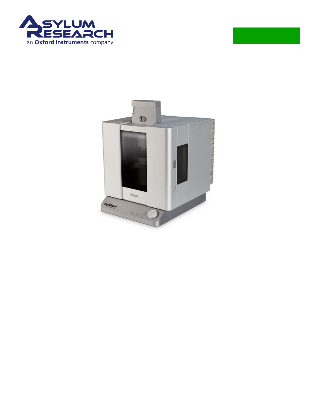
Cypher User Guide
Cypher SPM User Guide
USER GUIDE 2
Including beta (complete, reviewed) chapters. Including draft (nearly complete, not
reviewed) chapters.
Version 13, Revision: A-1714
Dated 10/25/2013
Asylum Research
an Oxford Instruments company
Page 2

Contents Contents
Contents
I System Overview and Powering Up . . . . . . . . . . . . . . . . . . . . . . . . . . . . . . 1
1 System Overview . . . . . . . . . . . . . . . . . . . . . . . . . . . . . . . . . . . . . . . 3
2 System Power Up . . . . . . . . . . . . . . . . . . . . . . . . . . . . . . . . . . . . . . . 10
II Standard Scanner . . . . . . . . . . . . . . . . . . . . . . . . . . . . . . . . . . . . . . . . . 12
3 Standard Scanner Overview . . . . . . . . . . . . . . . . . . . . . . . . . . . . . . . . . . 15
4 Tutorial: AC Mode in Air, Std. Scanner . . . . . . . . . . . . . . . . . . . . . . . . . . . . 17
5 Cantilever Holder Guide . . . . . . . . . . . . . . . . . . . . . . . . . . . . . . . . . . . . 49
6 Fluid Imaging in a Droplet . . . . . . . . . . . . . . . . . . . . . . . . . . . . . . . . . . . 53
7 iDrive Imaging . . . . . . . . . . . . . . . . . . . . . . . . . . . . . . . . . . . . . . . . . 75
8 Conductive AFM (ORCA) . . . . . . . . . . . . . . . . . . . . . . . . . . . . . . . . . . . 92
9 Scanning Tunneling Microscopy . . . . . . . . . . . . . . . . . . . . . . . . . . . . . . . 103
III Environmental Scanner . . . . . . . . . . . . . . . . . . . . . . . . . . . . . . . . . . . . . . 113
10 Environmental Scanner Overview . . . . . . . . . . . . . . . . . . . . . . . . . . . . . . . 115
11 Tutorial: AC Mode in Air, ES . . . . . . . . . . . . . . . . . . . . . . . . . . . . . . . . . . 130
12 Cantilever Holder Guide . . . . . . . . . . . . . . . . . . . . . . . . . . . . . . . . . . . . 141
13 Cell Body and Sample Stage Guide . . . . . . . . . . . . . . . . . . . . . . . . . . . . . . 147
14 Gas Handling and Leak Testing . . . . . . . . . . . . . . . . . . . . . . . . . . . . . . . . 173
15 Conductive AFM . . . . . . . . . . . . . . . . . . . . . . . . . . . . . . . . . . . . . . . . 178
IV Chassis and Enclosure . . . . . . . . . . . . . . . . . . . . . . . . . . . . . . . . . . . . . . 181
16 Tutorial: Scanner Exchange . . . . . . . . . . . . . . . . . . . . . . . . . . . . . . . . . . 183
support.asylumresearch.com Page ii
Page 3

Contents Contents
17 Optics . . . . . . . . . . . . . . . . . . . . . . . . . . . . . . . . . . . . . . . . . . . . . . 188
18 Laser Sources . . . . . . . . . . . . . . . . . . . . . . . . . . . . . . . . . . . . . . . . . 190
19 Air Temperature Controller . . . . . . . . . . . . . . . . . . . . . . . . . . . . . . . . . . 203
V Safety, Specifications, Set-up, and Shipping . . . . . . . . . . . . . . . . . . . . . . . . . 227
20 Safety Precautions . . . . . . . . . . . . . . . . . . . . . . . . . . . . . . . . . . . . . . . 229
21 Shipping or Moving . . . . . . . . . . . . . . . . . . . . . . . . . . . . . . . . . . . . . . 236
22 Troubleshooting and Maintenance . . . . . . . . . . . . . . . . . . . . . . . . . . . . . . 263
VI Bibliography, Glossary, and Index . . . . . . . . . . . . . . . . . . . . . . . . . . . . . . . 265
Index . . . . . . . . . . . . . . . . . . . . . . . . . . . . . . . . . . . . . . . . . . . . . . . . 268
support.asylumresearch.com Page iii
Page 4

Contents Contents
Introduction
CH AP TE R REV. 1702, DATED 10/21/2013, 22:07. US ER GUIDE REV. 1714, DATED 10/25/2013, 20:36.
AR Software Version It is assumed that AR Software version 13 or later is installed on your system. To
download the latest software, please register at our support site:
com.
Getting Help There are many ways to get help with your Asylum Research instrument, and it is always
free:
• Join the support site and download software, current manuals, and ask questions in our user forum.
http://support.asylumresearch.com. Note that all Asylum scientists are forum members
and frequent contributors.
http://support.asylumresearch.
• E-mail us at
• Call your local office or distributor.
• Call us at +1-805-696-6466. During US west coast business hours you will get a human being to
speak with. After hours you still have a good chance of catching one of our scientists. Within the
US you can call our toll free number if you wish (1-888-472-2795).
• If necessary we can initiate a remote session and have one of our scientists operate your AFM over
the internet.
Updates to the Manual Bundled with the software updates.
Send Feedback Send e-mail to [email protected] (<– clickable link) and mention which ver-
sion of the user guide you are using and what chapter and section your commenting on.
support.asylumresearch.com Page iv
Page 5
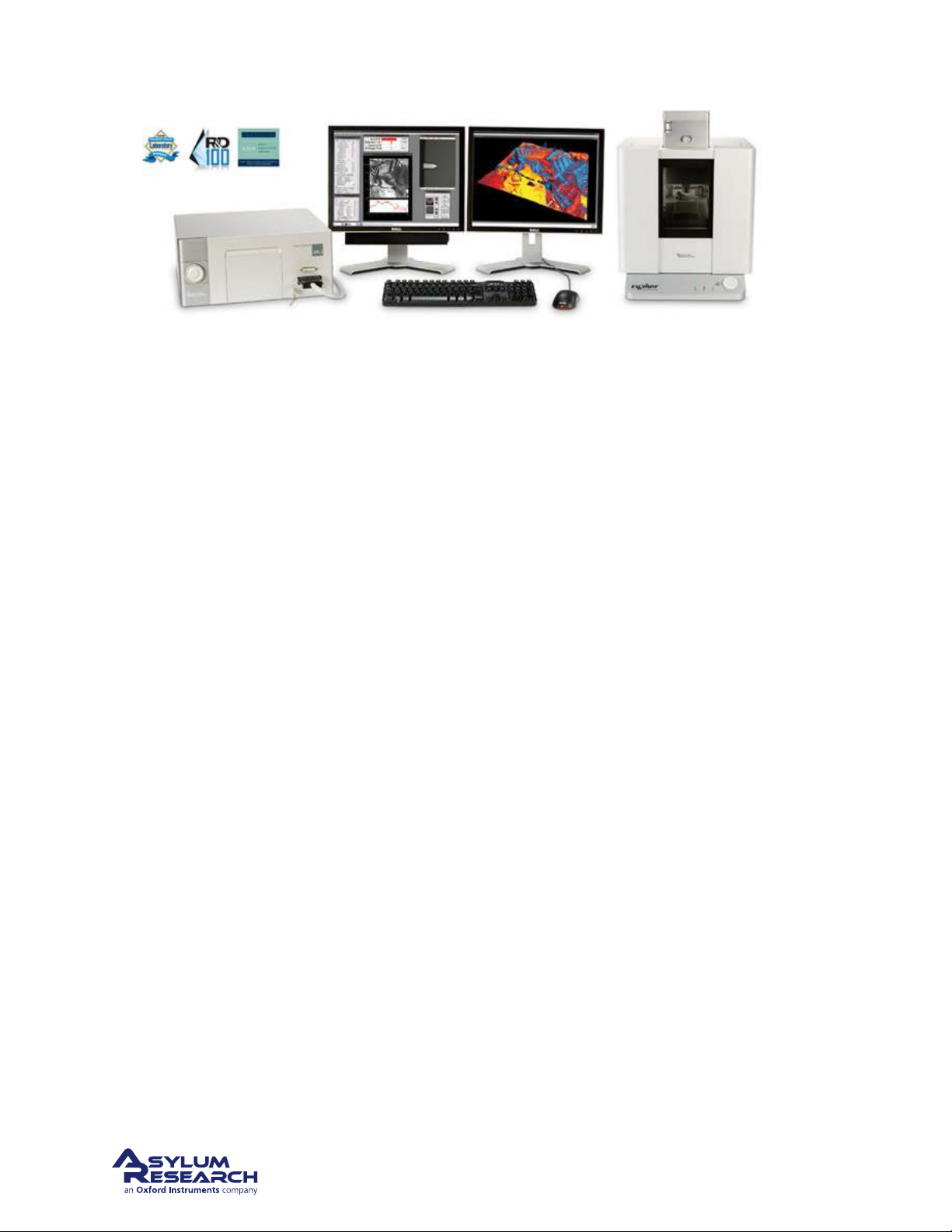
Part I
System Overview and Powering Up
Who is this part for? After the Cypher SPM has been installed in your lab and you (or someone in your
facility) have completed the initial training, this part of the user guide will review the main parts of the
instrument and software. Instrument power up is also covered.
support.asylumresearch.com Page 1
Page 6

Part Contents
1 System Overview . . . . . . . . . . . . . . . . . . . . . . . . . . . . . . . . . . . . . . . . 3
1.1 Basic Cypher SPM Hardware . . . . . . . . . . . . . . . . . . . . . . . . . . . . . . . . 3
1.2 Parts List . . . . . . . . . . . . . . . . . . . . . . . . . . . . . . . . . . . . . . . . . . 6
1.3 The Igor Pro Software Environment . . . . . . . . . . . . . . . . . . . . . . . . . . . . . 7
2 System Power Up . . . . . . . . . . . . . . . . . . . . . . . . . . . . . . . . . . . . . . . . 10
Page 7
Ch. 1. System Overview
1. System Overview
CH AP TE R REV. 1659, DATED 10/07/2013, 22:54. US ER GUIDE REV. 1714, DATED 10/25/2013, 20:36.
Chapter Contents
1.1 Basic Cypher SPM Hardware . . . . . . . . . . . . . . . . . . . . . . . . . . . . . . . . 3
1.2 Parts List . . . . . . . . . . . . . . . . . . . . . . . . . . . . . . . . . . . . . . . . . . 6
1.3 The Igor Pro Software Environment . . . . . . . . . . . . . . . . . . . . . . . . . . . . . 7
1.1. Basic Cypher SPM Hardware
Before starting the tutorial, the user should be familiar with the names and functionality of each of the
components of the Cypher. Don’t worry if you don’t understand everything in this section; the main goal
is just to get familiar with the basic purpose of each component of Cypher.
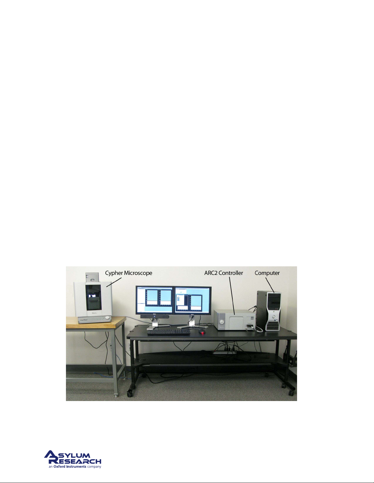
Figure 1.1 on page 3 shows
a typical set-up for the Cypher SPM. The top-level components are the computer, the ARC2 controller,
and the microscope itself.
Figure 1.1.: Ideally the Cypher SPM is set up as shown, with the controller and computer on one table
and the microscope on its own table. The air temperature controller (ATC) is not shown here. Please see
Chapter 19 on page 203 for more information.
support.asylumresearch.com Page 3
Page 8
Ch. 1. System Overview Sec. 1.1. Basic Cypher SPM Hardware
Objective
Scanner
View System
Enclosure
Chassis
Backpack
Computer The computer is the primary interface for controlling the microscope; its main communi-
cation is via a USB1.1 connection to the ARC2 AND via USB 2.0 directly from the computer to the
Cypher. See
ARC2 The ARC2 (Asylum Research Controller 2) is what is colloquially referred to as “the controller”.
Figure 22.1 on page 264 for recommended USB ports to use.
It houses power supplies and the necessary electronics for controlling the scan motion and acquiring
image data from the microscope.
Microscope The microscope itself, where the actual imaging takes place, is the heart of the AFM
system. Although the computer, controller, and microscope all comprise the Cypher, the microscope
itself will often be referred to as the Cypher.
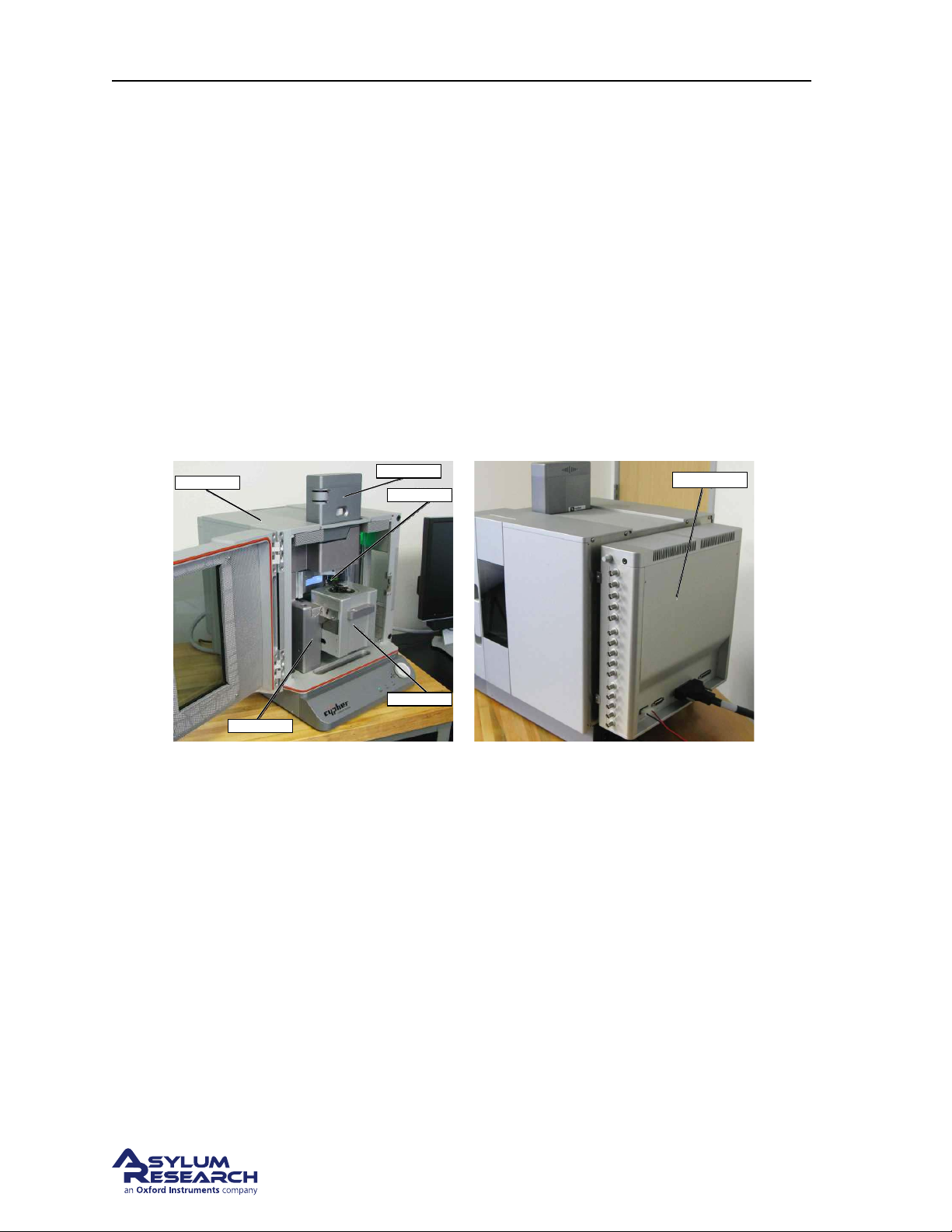
The microscope is comprised of five basic components (see
Figure 1.2 on page 4): enclosure, chassis,
camera, scanner, and backpack. The enclosure, chassis, and backpack are common to all versions of the
Cypher. In contrast, the scanner and camera are designed to be modular and easily interchanged by the
user.
(a) Front View. In this image the enclosure door is
open and the scanner is partially pulled out.
(b) Rear View
Figure 1.2.: Cypher parts basic nomenclature
Enclosure The primary function of the enclosure is to isolate the imaging portion of the microscope
from acoustic noise such as talking or music. Acoustic noise can cause the mechanical components
holding the sample to move, thereby showing up as noise in the microscope images. The secondary role
of the enclosure is to provide a local environment for the microscope itself, in which the temperature can
be controlled. Keeping the microscope at a constant temperature is important for maintaining long-term
control of the relative position between the cantilever and the sample. The air temperature controller
(ATC) is a Cypher option that can be used to maintain the temperature inside the enclosure. To learn
more about the enclosure and its options, please refer to
Chassis The chassis is the central structural unit supporting the scanner, camera, and head. While
Part IV on page 181.
the scanner and camera are modular units designed to be interchanged by the user, the head is just a
sub-assembly of the chassis and is permanently attached to the chassis. The head is responsible for
the detection of the cantilever deflection and has integrated motors that allow the user to automatically
support.asylumresearch.com Page 4
Page 9

Ch. 1. System Overview Sec. 1.1. Basic Cypher SPM Hardware
position the laser spot onto the cantilever. The objective lens attached to the head has two important
functions: it focuses the laser light onto the cantilever and works with the camera to create an optical
view of the sample. To learn more about the chassis and its options, please refer to
Camera The camera (also called the “view module”) is a user changeable module that provides a top
Part IV on page 181.
down optical view of the cantilever and sample. It is comprised of a tube lens, Koehler illumination
with an LED source, and a digital camera. The camera module uses the objective lens in the head to
create the optical view. The standard camera module has a bright field reflected light topology and has
a 690µm by 920µm field of view with sub-micron resolution. Depending on the application, the view
module can be swapped by the user in about 10 minutes, but requires Allen wrenches to complete.
Scanner The primary function of the scanner is to move the sample relative to the cantilever during
imaging and other measurements such as force curves. There are various scanner modules which excel
at various tasks. The Cypher scanners are “sample scanners”, which means that relative to the room
that the microscope is sitting in, the cantilever is stationary and the sample moves. The scanner is a
modular unit that can be interchanged by the user depending on the application, although at present
there is only a single scanner available. Thus far the scanner modules are based on a flexure design that
uses piezoelectric stacks to move the sample up to 30µm in XY and 5µm in Z. The secondary function
of the scanner is to provide motorized course positioning of the cantilever relative to the sample in
the Z-axis. The cantilever holder is a component of the scanner that physically holds the cantilever
during imaging. There are different cantilever holders for air and liquid operations, and there are also
application specific holders for techniques like scanning tunneling microscopy (STM), see
Chapter 9
on page 103. Each scanner type has its own family of cantilever holders and other accessories. The
available scanner modules are:
• The Standard scanner, described in Part II on page 12.
• The Environmental scanner, described
Backpack The backpack is located on the backside of the enclosure and houses a very powerful set of
Part III on page 113.
digital and analog electronics that extend the functionality of the ARC2. Like the ARC2, the backpack
has ADCs, DACs, BNC connections, and a CrossPoint switch. .
Q Why is there both a backpack and a controller? Isn’t the backpack redundant since there is
already a controller?
A In a typical AFM design, most of the electronics housed in the Cypher backpack would be
located in the controller. The backpack, however, moves these electronics closer to the microscope; Cypher is able to achieve very low noise levels in part because of the proximity between
some of its electronics and the actual microscope. Keeping these low noise electronics external
to the enclosure balances noise performance with the management of the heat generated by
electronics.
support.asylumresearch.com Page 5
Page 10
Ch. 1. System Overview Sec. 1.2. Parts List
Q AFM or SPM? What is the difference?
A AFM stands for Atomic Force Microscope. It scans a cantilever over a sample to generate an
image. SPM stands for Scanning Probe Microscope. It is the more general, all encompassing
term, which also includes techniques that image using non-cantilever probes such as sharp
metal needles (Scanning Tunneling Microscopy), optical fibers (NSOM) or tiny hollow glass
tubes (SICM). Since Cypher is capable of both AFM and STM, it is classified as an SPM. You
may see Cypher referred to in the context of an AFM when its AFM-like functions are being
described.
1.2. Parts List
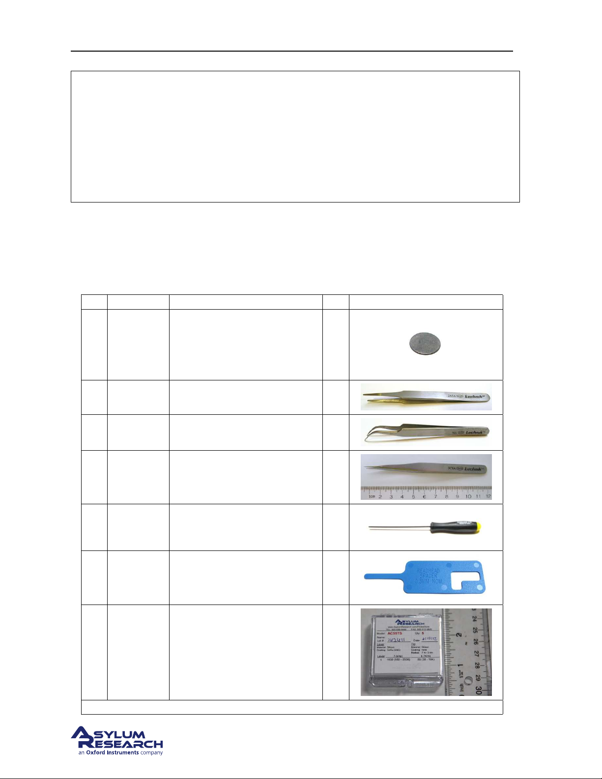
The contents of the accessory kit which accompanies Cypher. Asylum Inventory Number 900.110.1.
These parts accompany the AFM irrespective of the type of scanners you purchased.
Itm Part # Item Description Qty Picture
15mm AFM Specimen Disc.
1 080.122
2 290.101
3 290.102
4 290.103
5 290.139 Hex Driver, 1/16” Small Handle. 2
6 312.003
Also available from Ted Pella,
part number 16218.
2A Tweezer, SA Tapered Round
Blunt, Standard Grade.
7Tweezer, SA Curves Sharp,
Standard Grade.
3A Tweezer, Extra Fine Sharp,
Standard Grade.
Renishaw Encoder Readhead
Spacer (0.8mm).
50
1
2
1
1
7
803. OLY.
AC 55 TS
Olympus Cantilevers, Model AC
55 TS.
The scale in the photos is in cm and mm.
support.asylumresearch.com Page 6
5
Page 11
Ch. 1. System Overview Sec. 1.3. The Igor Pro Software Environment
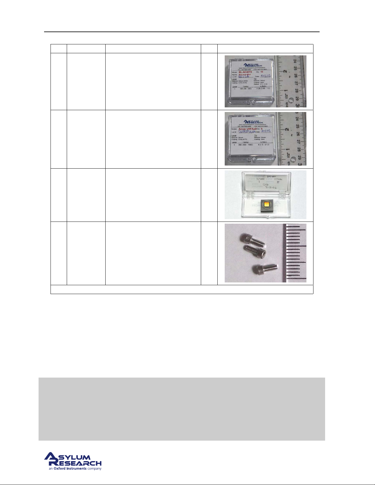
Itm Part # Item Description Qty Picture
803. OLY.
8
BL- AC 40
TS
804. NW.
9
ARROW -
UHF AUD
10 900.237
1-72 x
11
3/16”
SHCS SS
Olympus Biolevers (Mini):
Model BL - AC40TS.
Nanoworld Cantilevers, Model:
ARROW UHFAuD
AR calibration Grating - Steel
Puck Mounted.
1-72 x 3/16” screw, spares.
Fastens the cantilever holder
onto the standard scanner
Step 6 on page 20) and also fits
(
the cantilever holder changing
stations.
10
5
1
5
The scale in the photos is in cm and mm.
1.3. The Igor Pro Software Environment
The Asylum Research software is primarily written within the programming environment of the commercially available software package Igor Pro, which is developed by WaveMetrics. Igor Pro itself has
nothing to do with scanning probe microscopes. Rather it is a stand alone program that has extensive
scientific graphing, data analysis, image processing and macro programming capabilities.
The “Volume I - Getting Started” manual found on the WaveMetrics website
www.wavemetrics.com) takes two to three hours to complete and is an excellent
(
Tip
way to learn about the basic graphing and analysis functionality of Igor Pro.
Although it is not necessary to complete the Igor Pro portion of the “Getting
Started” manual at this time, it is a highly recommended part of all new user
training.
support.asylumresearch.com Page 7
Page 12
Page 13

Ch. 1. System Overview Sec. 1.3. The Igor Pro Software Environment
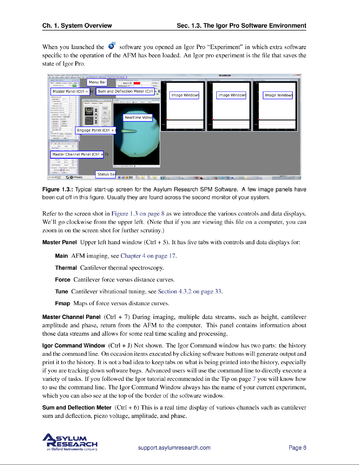
Engage Panel (Ctrl + 8) This panel controls the entire process of the cantilever approach to the sample.
Its three tabs control:
Approach Motorized approach of cantilever and microscope objective toward the sample.
Detector Centering of reflected light beam (laser or SLD) onto the optical detector.
Prefs Preferences for the engage process such as approach speed and approach step size.
Real Time Image Display This is an example of an image window, in this case displaying the individual
lines of the sample topography as the cantilever moves left to right over the sample. There is usually
one such window per active tab in the ‘Master Channel Panel’ (Lower left hand window). The amplitude
and phase data windows are to the right of this clipped screen shot. While this panel is primarily a data
display, right clicking with the mouse can activate various commands such as ‘Zoom’ and ‘Translate’.
The white area at the bottom of this window shows a real time oscilloscope view of the most recent line
of image data.
Scope Graph This oscilloscope view shows a graph of the most current scan line. Both trace and retrace
can be selected on the ‘Master Channel Panel’.
Q Oops! I accidentally closed one of the control panel windows. How do I get it back?
A You can reactivate the panels via AFM Controls in the top menu bar.
A few other things of note are:
Menu Bar Along the top of the screen. There are many more controls which can be invoked by items in
the menu bar. Menu items to the left are typically standard Igor Pro items, with some Asylum Research
functionality. Items to the right of “help” are exclusively SPM related. In particular, the AFM Controls
menu item is a complete list of all real time controls and the AFM Analysis menu item is a complete list
of all offline controls.
Status Bar Along the bottom of the screen. Icon controls relate to the status of connected instrument
components. The low level software version is also displayed.
We won’t dwell on the purpose of all these controls but will proceed with the general process of imaging
a sample. This will necessarily cover the most pertinent software controls.
Note that nearly each individual item in the software control panels has a small
Tip
question mark button next to it. Click the button to read the relevant parts of the
software help file.
support.asylumresearch.com Page 9
Page 14
Page 15
Ch. 2. System Power Up
5.
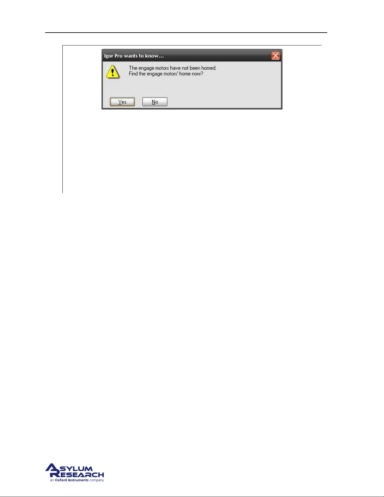
• Once the software has finished initializing, you will get a prompt asking if you would
like to home the engage motors.
• If necessary, slide the scanner all the way into the chassis. Close the microscope
enclosure door. For safety reasons the motors cannot home unless the door remains
closed during the process.
• Click ‘Yes’ . You will hear motors moving during the homing process, which will take
about 20 seconds.
6. If you are new to the Cypher AFM system, please take the tutorial which is appropriate for your
scanner:
• For the standard scanner see: Chapter 4 on page 17.
• For the Environmental Scanner see: ??
on page ??.
support.asylumresearch.com Page 11
Page 16
Part II
Standard Scanner
Who is this part for? After the Cypher S SPM has been installed in your lab and you (or someone in
your facility) have completed the initial training, this part of the user guide will be the principal reference
for operating the instrument. Although written with the novice user in mind, experienced SPM users
should complete the basic imaging tutorial at least once before attempting to use this instrument.
support.asylumresearch.com Page 12
Page 17

Part Contents
3 Standard Scanner Over view . . . . . . . . . . . . . . . . . . . . . . . . . . . . . . . . . . . 15
4 Tutorial: AC Mode in Air, Std. Scanner . . . . . . . . . . . . . . . . . . . . . . . . . . . . . 17
4.1 Required Materials . . . . . . . . . . . . . . . . . . . . . . . . . . . . . . . . . . . . . 18
4.2 Loading Lever and Sample . . . . . . . . . . . . . . . . . . . . . . . . . . . . . . . . . 18
4.3 Engaging the Surface . . . . . . . . . . . . . . . . . . . . . . . . . . . . . . . . . . . . 26
4.4 Imaging . . . . . . . . . . . . . . . . . . . . . . . . . . . . . . . . . . . . . . . . . . . 40
4.5 Stopping Imaging . . . . . . . . . . . . . . . . . . . . . . . . . . . . . . . . . . . . . 47
4.6 Shutting the System Down . . . . . . . . . . . . . . . . . . . . . . . . . . . . . . . . . 47
5 Cantilever Holder Guide . . . . . . . . . . . . . . . . . . . . . . . . . . . . . . . . . . . . . 49
5.1 Identifying Cantilever Holders . . . . . . . . . . . . . . . . . . . . . . . . . . . . . . . . 49
5.2 Cantilever Holder Changing Stations . . . . . . . . . . . . . . . . . . . . . . . . . . . . 51
6 Fluid Imaging in a Droplet . . . . . . . . . . . . . . . . . . . . . . . . . . . . . . . . . . . . 53
6.1 Nomenclature . . . . . . . . . . . . . . . . . . . . . . . . . . . . . . . . . . . . . . . . 54
6.2 Parts List . . . . . . . . . . . . . . . . . . . . . . . . . . . . . . . . . . . . . . . . . . 54
6.3 Preparing for Imaging . . . . . . . . . . . . . . . . . . . . . . . . . . . . . . . . . . . . 56
6.4 Imaging with the Droplet Holder . . . . . . . . . . . . . . . . . . . . . . . . . . . . . . 65
6.5 Removal and Storage . . . . . . . . . . . . . . . . . . . . . . . . . . . . . . . . . . . . 69
6.6 Cleaning and Repair . . . . . . . . . . . . . . . . . . . . . . . . . . . . . . . . . . . . 69
7 iDrive Imaging . . . . . . . . . . . . . . . . . . . . . . . . . . . . . . . . . . . . . . . . . . 75
7.1 Nomenclature . . . . . . . . . . . . . . . . . . . . . . . . . . . . . . . . . . . . . . . . 76
7.2 Cleaning and Repair . . . . . . . . . . . . . . . . . . . . . . . . . . . . . . . . . . . . 80
7.3 Older Models . . . . . . . . . . . . . . . . . . . . . . . . . . . . . . . . . . . . . . . . 83
8 Conductive AFM (ORCA) . . . . . . . . . . . . . . . . . . . . . . . . . . . . . . . . . . . . 92
8.1 Parts list . . . . . . . . . . . . . . . . . . . . . . . . . . . . . . . . . . . . . . . . . . 92
8.2 The ORCA Amplifier . . . . . . . . . . . . . . . . . . . . . . . . . . . . . . . . . . . . 94
8.3 Preparing for Imaging . . . . . . . . . . . . . . . . . . . . . . . . . . . . . . . . . . . . 96
8.4 Imaging with the ORCA . . . . . . . . . . . . . . . . . . . . . . . . . . . . . . . . . . . 99
8.5 Testing the ORCA Amplifier . . . . . . . . . . . . . . . . . . . . . . . . . . . . . . . . . 99
Page 18

PART CONTENTS PART CONTENTS
9 Scanning Tunneling Microscopy . . . . . . . . . . . . . . . . . . . . . . . . . . . . . . . . 103
9.1 Introduction and Preparation . . . . . . . . . . . . . . . . . . . . . . . . . . . . . . . . 103
9.2 Required Equipment . . . . . . . . . . . . . . . . . . . . . . . . . . . . . . . . . . . . 103
9.3 Preparing an STM sample . . . . . . . . . . . . . . . . . . . . . . . . . . . . . . . . . 104
9.4 Load the tip . . . . . . . . . . . . . . . . . . . . . . . . . . . . . . . . . . . . . . . . . 105
9.5 Zero Various Offsets . . . . . . . . . . . . . . . . . . . . . . . . . . . . . . . . . . . . 105
9.6 Set up to engage . . . . . . . . . . . . . . . . . . . . . . . . . . . . . . . . . . . . . . 107
9.7 Set scan parameters . . . . . . . . . . . . . . . . . . . . . . . . . . . . . . . . . . . . 108
9.8 STM IV Curves . . . . . . . . . . . . . . . . . . . . . . . . . . . . . . . . . . . . . . . 108
9.9 Set IV Parameters . . . . . . . . . . . . . . . . . . . . . . . . . . . . . . . . . . . . . 109
9.10 STM probes . . . . . . . . . . . . . . . . . . . . . . . . . . . . . . . . . . . . . . . . 111
9.11 Troubleshooting . . . . . . . . . . . . . . . . . . . . . . . . . . . . . . . . . . . . . . . 112
support.asylumresearch.com Page 14
Page 19
Ch. 3. Standard Scanner Overview
3. Standard Scanner Overview
CH AP TE R REV. 1659, DATED 10/07/2013, 22:54. US ER GUIDE REV. 1714, DATED 10/25/2013, 20:36.
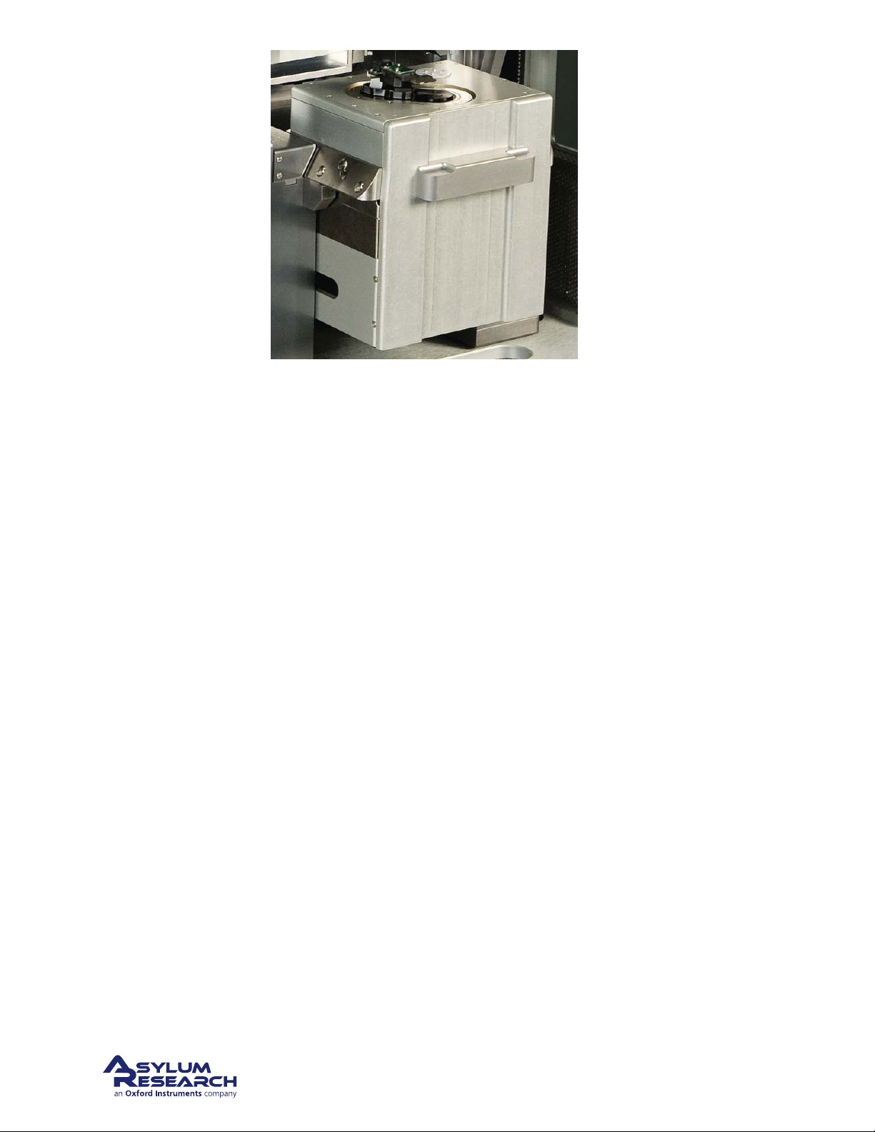
The module dubbed “the scanner” contains the entire mechanics of the AFM except for the optical
means for detecting cantilever deflection. This includes:
• Actuators and sensors for closed loop XY scanning of the sample.
• An actuator and sensor for the sample Z motion.
• A cantilever holder and mechanical means for engaging the cantilever with the sample surface.
Since Cypher’s scanners are whole AFMs unto themselves, each comes with its own dedicated collection
accessories such as cantilever holders and sample stages. In other words, a cantilever holder for one
scanner usually does not fit onto a different scanner. Also, an expert user of one model of scanner will
not necessarily know anything about operating another model.
This part of the user guide describes in many chapters the use of the Standard Scanner and its many
accessories. Once the scanner is exchanged for another, as described in
different part of the user guide will need to be consulted. Typically the first user of a new scanner will
need to be trained by Asylum Research personnel.
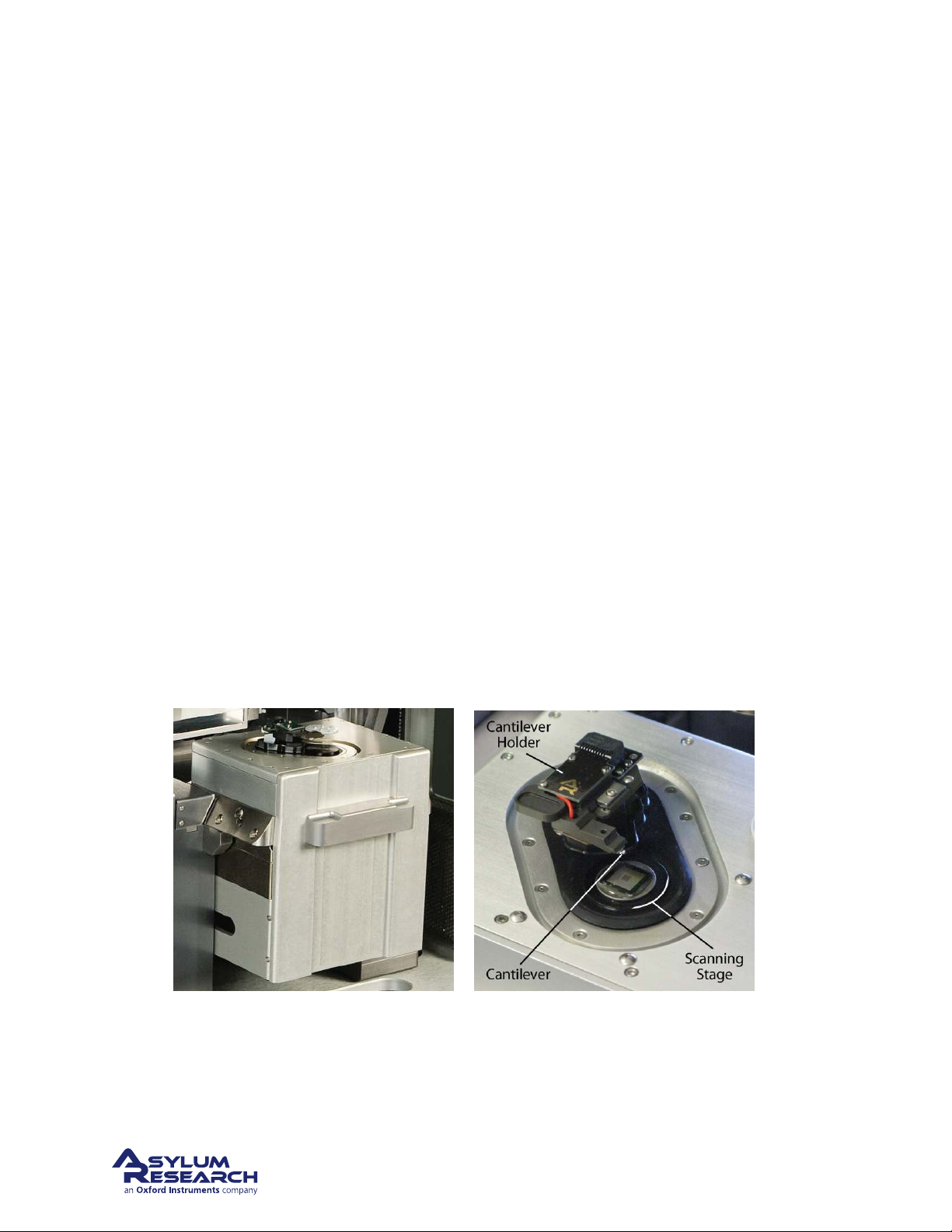
(a) Standard Scanner. (b) Names of the basic components.
Figure 3.1.: The Standard Scanner
Chapter 16 on page 183, an
Figure
The standard scanner is included with the “Cypher S” AFM, but can also be purchased separately. The
Figure 3.1 on page 15 shows the standard scanner partially withdrawn from the rest of the AFM.
BETA
Page 15
Page 20
Ch. 3. Standard Scanner Overview
Standard scanner is designed primarily for imaging in ambient conditions, either in air or in a liquid
droplet. The optical access to the sample and cantilever is superior to other cypher scanner models.
Many Standard Scanner cantilever holders allow for a variety of imaging modes. See
page 49 for more information.
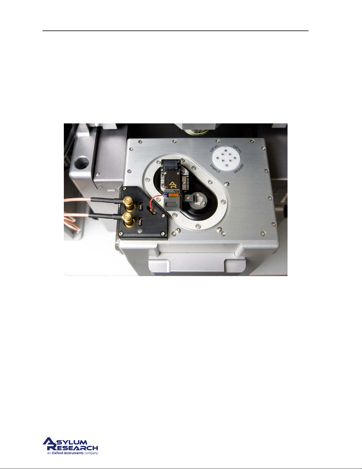
The Scanner itself comes in regular and high voltage models.
magnetic high voltage contact and specialized cantilever holder with high voltage connection to the tip.
This arrangement is typically use for PFM techniques. This topic is covered in depth in Applications
Guide, Chapter: PFM Using DART and Applications Guide, Chapter: Single Frequency PFM.
Figure 3.2 on page 16 shows the a
Chapter 5 on
Figure 3.2.: Detailed view of the high voltage option.
BETA
Page 16
Page 21

Ch. 4. Tutorial: AC Mode in Air, Std. Scanner
4. Tutorial: AC Mode Imaging in Air with the
Standard Scanner
CH AP TE R REV. 1714, DATED 10/25/2013, 20:36. US ER GUIDE REV. 1714, DATED 10/25/2013, 20:36.
Chapter Contents
4.1 Required Materials . . . . . . . . . . . . . . . . . . . . . . . . . . . . . . . . . . . . . 18
4.2 Loading Lever and Sample . . . . . . . . . . . . . . . . . . . . . . . . . . . . . . . . . 18
4.3 Engaging the Surface . . . . . . . . . . . . . . . . . . . . . . . . . . . . . . . . . . . . 26
4.3.1 Bringing the Cantilever Close to the Sample . . . . . . . . . . . . . . . . . . . 26
4.3.2 Tuning the Cantilever and Setting Scan Parameters . . . . . . . . . . . . . . . . 33
4.3.3 Landing the Tip . . . . . . . . . . . . . . . . . . . . . . . . . . . . . . . . . . 37
4.4 Imaging . . . . . . . . . . . . . . . . . . . . . . . . . . . . . . . . . . . . . . . . . . . 40
4.4.1 Set-Up and Initial Parameter Selection . . . . . . . . . . . . . . . . . . . . . . 40
4.4.2 Start Imaging and Parameter Tuning . . . . . . . . . . . . . . . . . . . . . . . 42
4.4.3 Image Refinement . . . . . . . . . . . . . . . . . . . . . . . . . . . . . . . . . 45
4.5 Stopping Imaging . . . . . . . . . . . . . . . . . . . . . . . . . . . . . . . . . . . . . 47
4.6 Shutting the System Down . . . . . . . . . . . . . . . . . . . . . . . . . . . . . . . . . 47
This tutorial provides a quick path to learning the basic operation of the Cypher SPM equipped with the
Standard Scanner. If you own the Environmental Scanner, please follow the tutorial in
Chapter 11 on
page 130. The tutorial contains a set of steps that will teach a new user with a basic understanding of
AFM operation how to obtain an AC mode topography image in air.
All new users should complete and understand this “AC Mode Imaging in Air” tutorial
before attempting any imaging.
The Cypher is a research grade instrument and improper use of the instrument can cause both damage
to the instrument and injury to the user. This tutorial will take approximately 3 hours.
Before you start:
• You should understand the aspects of running this system safely: (
Chapter 20 on page 229.)
• You should be familiar with the basic names of the hardware components and software controls
(
Chapter 1 on page 3.)
• You should have powered up the Cypher and launched the software: (
Chapter 2 on page 10.)
support.asylumresearch.com Page 17
Page 22
Ch. 4. Tutorial: AC Mode in Air, Std. Scanner Sec. 4.1. Required Materials
4.1. Required Materials
This tutorial is designed to be performed, not merely read. You will learn the most if you operate the
instrument yourself, with an experienced user watching, providing advice.
It will be necessary to gather a few items prior to beginning the tutorial:
1. Cantilevers: You will need an
AC160TS cantilever, which is manufactured by Olympus. The
AC160TS, with a spring constant of ~42N/m and a resonance frequency of ~300kHz, is a workhorse
for AC mode imaging in air. Every Cypher ships with a package of AC160s, but if these cantilevers are unavailable, any cantilever with a similar spring constant and resonance frequency
should work fine.
2. Sample: The tutorial will use the
Asylum Research calibration grating that ships with every sys-
tem (Asylum Part# 290.237).
3. Tweezers: It is preferable to use tweezers with curved tips (for example, Asylum Part# 290.102).
4. Wrench: A 1/16” ball head wrench (for example, Asylum Part# 290.139) is required.
5. SPM: This tutorial is designed for a Cypher equipped with the Standard Scanner and a large spot
SLD or Laser Module (See
Chapter 18 on page 190).
4.2. Loading the Cantilever and Sample
This section covers sample and cantilever loading as well as the course approach of the cantilever tip
toward the sample.
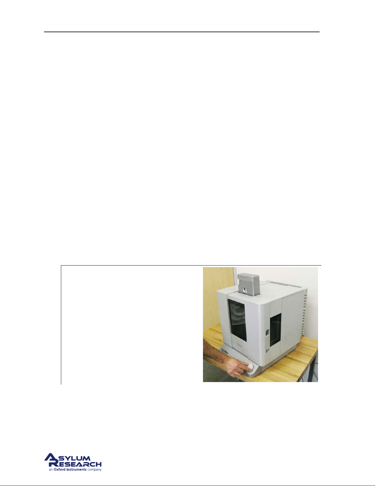
Raise the cantilever holder:
• Rotate the ‘Engage Control Knob’ on the
Cypher clockwise and hold it until the
cantilever holder is far from the sample
1.
or is at its upper limit of travel.
Note Although it is not required, for safety
reasons we recommend making motor moves
with the door closed. Beware of pinch points
Figure 20.1 on page 230).
(
support.asylumresearch.com Page 18
Page 23
Ch. 4. Tutorial: AC Mode in Air, Std. Scanner Sec. 4.2. Loading Lever and Sample
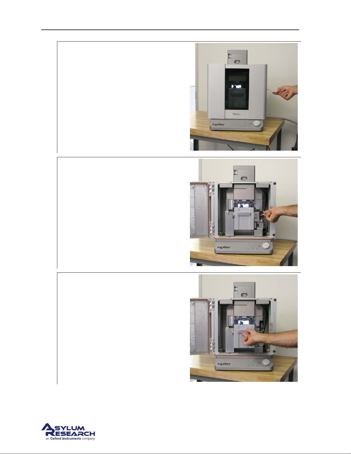
Open enclosure:
2.
• Lift the door latch and open the
enclosure door.
Unlock scanner:
3.
• Lift the lever to the right of the scanner.
Pull the scanner out:
• Pull the scanner forward gently and stop
4.
when it is about halfway out. If you
continue pulling the scanner, at some
point you will feel resistance and should
pull no further.
support.asylumresearch.com Page 19
Page 24
Ch. 4. Tutorial: AC Mode in Air, Std. Scanner Sec. 4.2. Loading Lever and Sample
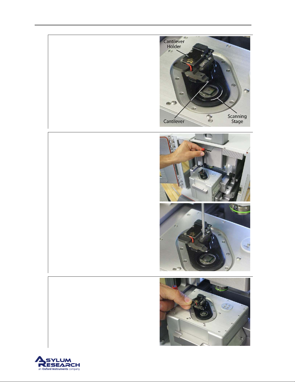
Familiarize yourself with the sample area:
5.
• While it may look solid, the scanner
stage moves the sample in the X, Y, and
Z directions imperceptibly up to 40μm.
Release the cantilever holder:
• Loosen the screw clamping the
cantilever holder. One turn
counterclockwise should be enough.
• Replace the tool in its storage place
(hole in the chassis to the left of the
scanner).
6.
Remove the cantilever holder:
7.
• Hold by the tab with the circular recess
and pull straight out towards you.
support.asylumresearch.com Page 20
Page 25
Ch. 4. Tutorial: AC Mode in Air, Std. Scanner Sec. 4.2. Loading Lever and Sample
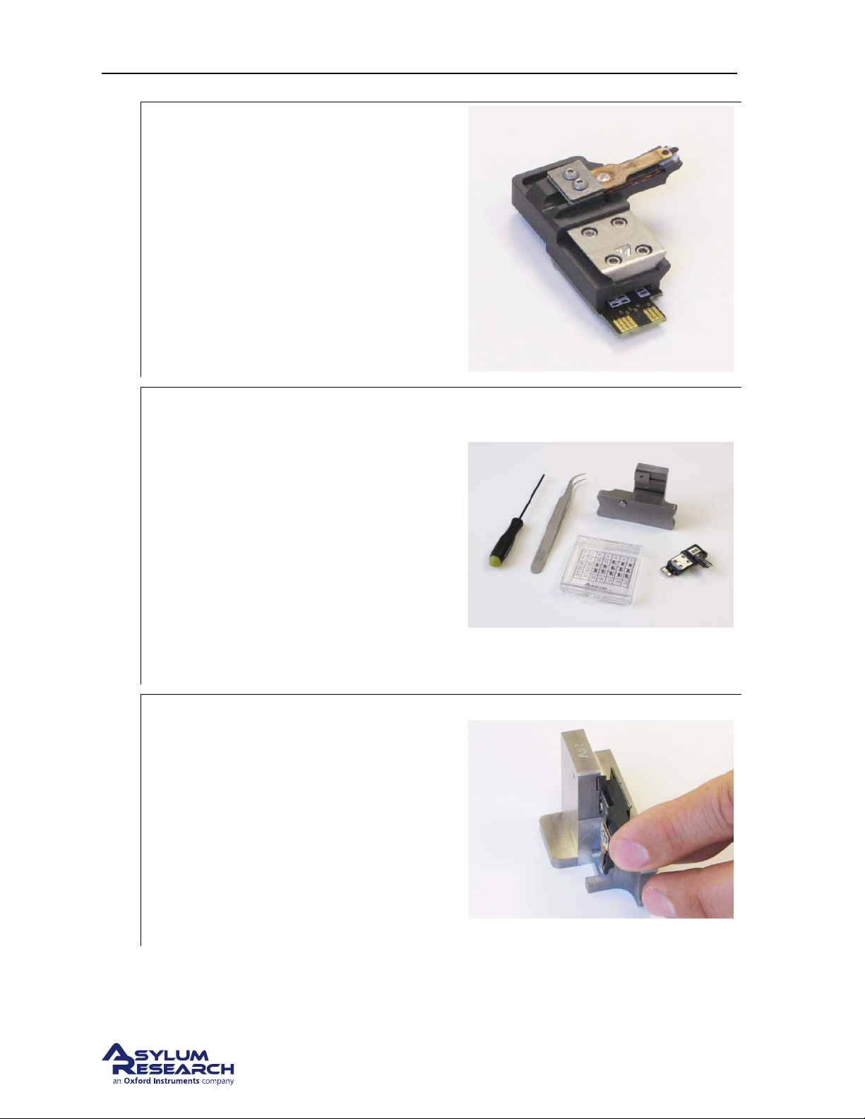
Select AC mode cantilever holder:
• Identify the cantilever holder. This
demo requires the standard “AC Air”
8.
holder, Asylum Part# 901.705.
Note To learn more about cantilever holders
for the standard scanner, please refer to
Chapter 5 on page 49.
Prepare cantilever mounting workspace:
• Set out your changing station, tweezers,
and cantilevers on a clean, well lighted
surface. Make sure that the changing
station is labeled “Air” (there is also a
“Droplet” changing station for the
9.
droplet holder.)
• A low power binocular dissection
stereoscope with light source can be
useful for some of the following steps.
• Cleaning the tweezer tips with alcohol
improves the handling of the cantilevers.
Mount the cantilever holder in the changing
station:
• Carefully insert the cantilever holder as
shown. The V-shaped piece of metal on
10.
the back of the holder slides into the
dovetail joint on the changing station.
The cantilever should be pointing down.
• If the cantilever holder does not slide in
easily, loosen the screw on the clamping
mechanism.
support.asylumresearch.com Page 21
Page 26
Ch. 4. Tutorial: AC Mode in Air, Std. Scanner Sec. 4.2. Loading Lever and Sample
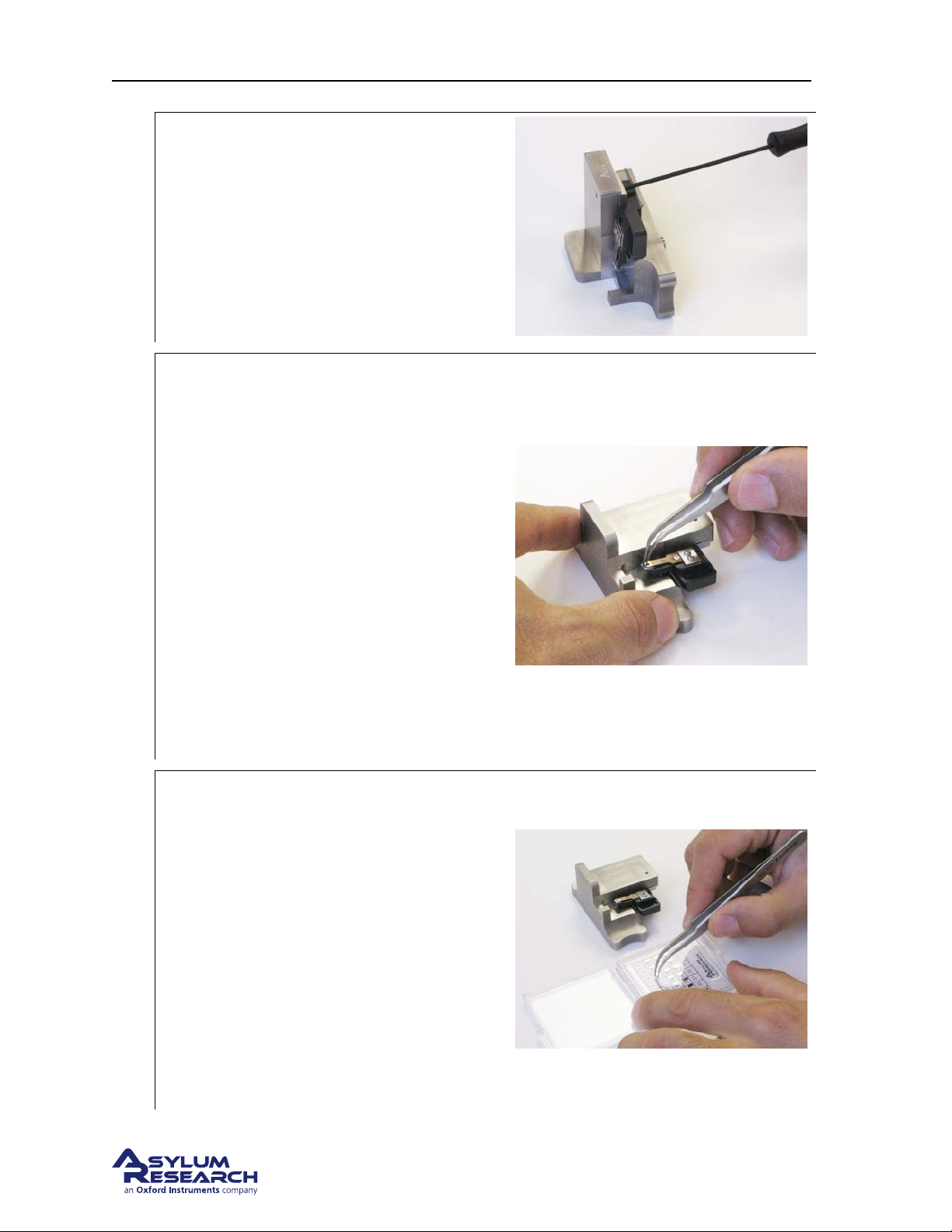
Tighten the clamp:
11.
• Once the cantilever holder is fully
inserted, use the ball head wrench to
gently tighten the clamp.
Remove the old cantilever:
• Position the changing station as shown,
on a flat hard surface.
• Take the tweezers in your dominant
hand.
• Press down on the station, as shown,
with your other hand. This depresses a
12.
button on the bottom of the station
which drives a pin up under the
cantilever retaining clip.
• Remove the cantilever and release
pressure on the station.
• Inspect the cantilever area for tiny
silicon grit and blow clean with
compressed air if necessary.
Select new cantilever:
• Select a new cantilever and pick it up
with tweezers.
• Close the box! Ruining $1k of levers by
putting your hand on an open box is not
unheard of.
13.
Note If your lab saves some old cantilevers,
consider practicing with a “dummy”
cantilever.
Tip Some find it useful to first lay the chip
down on a non-sticky surface and re-grip it
before continuing.
support.asylumresearch.com Page 22
Page 27
Ch. 4. Tutorial: AC Mode in Air, Std. Scanner Sec. 4.2. Loading Lever and Sample
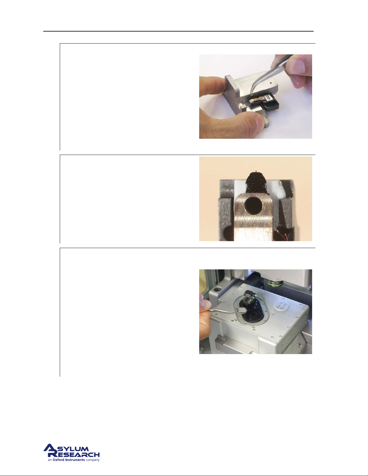
Load new cantilever:
• Place and center the cantilever in the
holder (also see photo in next step for
alignment).
14.
• A good technique is to release pressure
on the changing station while still
gripping the cantilever chip with
tweezers. This prevents misalignment
caused by the cantilever chip sticking to
the tweezers.
Check cantilever alignment:
• A properly aligned cantilever seen from
15.
above.
• It helps to do this at least once under a
binocular stereo microscope.
Prepare scanner and load sample:
16.
• Leave the cantilever holder in the
changing station for now.
• Remove any sample that may be present
on the scanner.
• Wipe the scanner stage (defined in
Step 5 on page 19) clean with a soft
cloth. Any dust or grit will prevent the
sample disk from being properly seated.
• Place the Asylum Research calibration
grating onto the scanner stage. It will
attach magnetically.
support.asylumresearch.com Page 23
Page 28
Ch. 4. Tutorial: AC Mode in Air, Std. Scanner Sec. 4.2. Loading Lever and Sample
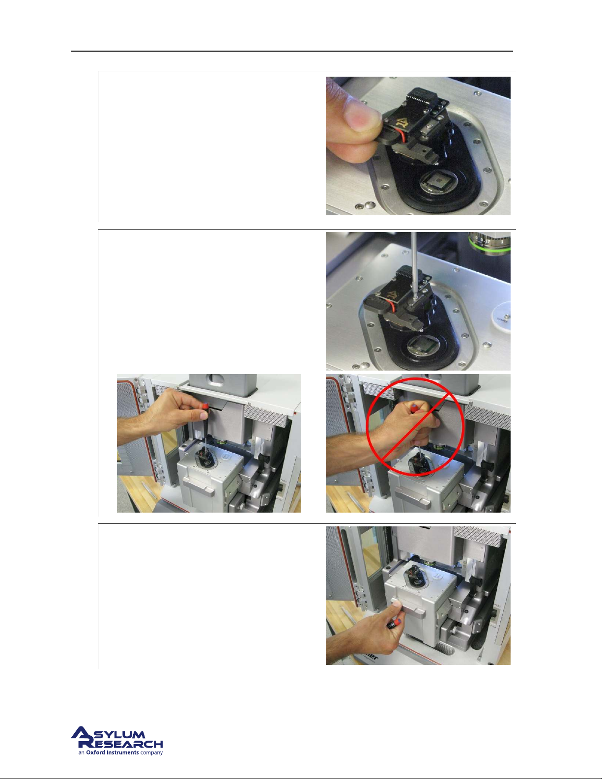
Insert cantilever holder into scanner:
• Remove the cantilever holder from the
changing station.
17.
• Insert the cantilever holder into the
scanner. Pay attention that the metal
dovetail engages properly.
• If it will not go in, loosen the screw by
half a turn (see
Tighten cantilever holder:
• Use the ball headed wrench to gently
tighten the screw that clamps the
cantilever holder.
• Don’t use your whole hand! Be gentle!
18.
Step 6 on page 20).
Slide scanner into chassis, lock down:
• Gently slide the scanner back into the
19.
chassis.
• Push the lever at the right of the scanner
downward to secure the scanner in
place.
support.asylumresearch.com Page 24
Page 29
Ch. 4. Tutorial: AC Mode in Air, Std. Scanner Sec. 4.2. Loading Lever and Sample
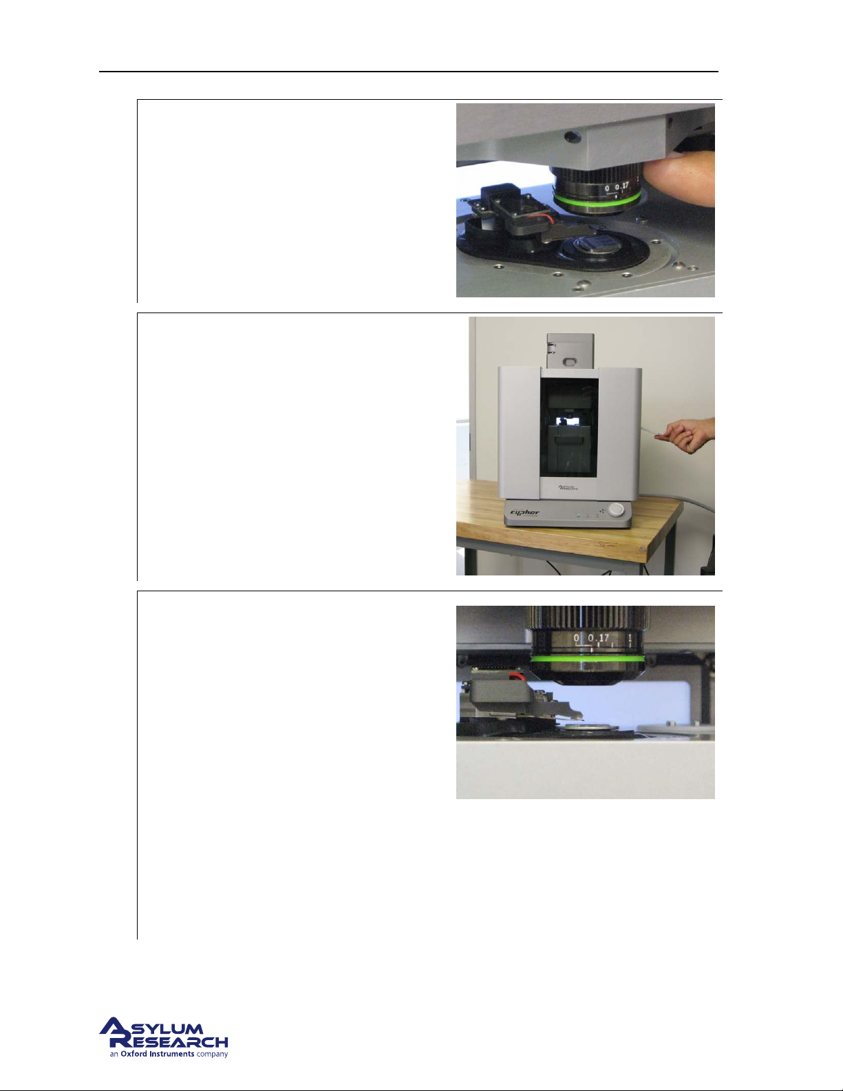
Check correction collar:
• Check that the green correction collar
20.
on the objective is set to zero (this
cantilever holder has no glass window
through which the light must focus).
Close enclosure door:
21.
• Gently close the door and latch it.
Motor cantilever toward sample:
• Place your eyes level with the cantilever
and sample, so you can clearly see the
gap between cantilever and sample.
• Slowly turn the ‘Engage Control Knob’
on the AFM enclosure
counterclockwise. This will lower the
22.
cantilever holder and objective toward
the sample. The more you turn, the
faster it goes.
• Close the gap between tip and sample to
about 1 millimeter. There is no harm in
playing it safe and stopping a little
farther away. It will only cause the
automated engage to take a little longer.
23. This concludes the manual interaction with Cypher. We next turn our attention to the computer.
Warning: Nothing but your attentiveness will
prevent the cantilever holder from crashing
into the sample. If you crash the cantilever
holder you may cause SERIOUS damage to
your cantilever holder and scanner.
support.asylumresearch.com Page 25
Page 30
Page 31
Ch. 4. Tutorial: AC Mode in Air, Std. Scanner Sec. 4.3. Engaging the Surface
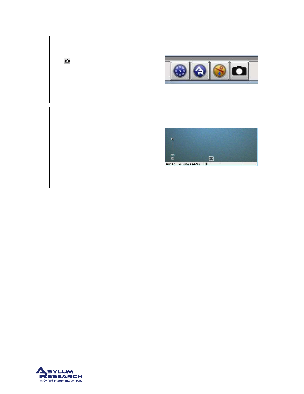
Open video window (If necessary):
• In the software, click on the camera icon
on the bottom status bar.
4.
• This will open the video window (or
highlight it in case it was already open),
which displays an optical view of the
cantilever and sample.
Setting video zoom and illumination:
• IMPORTANT: Slide the vertical slider
at the lower left corner of the video
window all the way to the bottom.
5.
“Zoom 1.0” will be indicated just below.
• Turn up the illumination by moving the
slider (on the bottom of the video
window) to the right a quarter or third of
its full range.
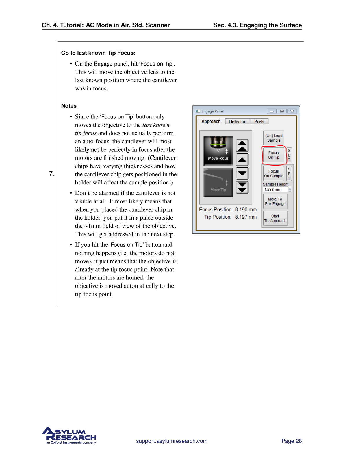
6. Familiarize yourself with the Approach tab on the Engage Panel as described next in Step 7 on
page 27
. Failure to understand the Approach controls may lead to serious damage to the Cypher.
support.asylumresearch.com Page 27
Page 32
Page 33
Page 34
Ch. 4. Tutorial: AC Mode in Air, Std. Scanner Sec. 4.3. Engaging the Surface
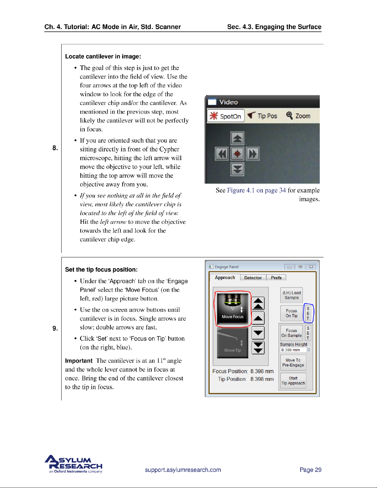
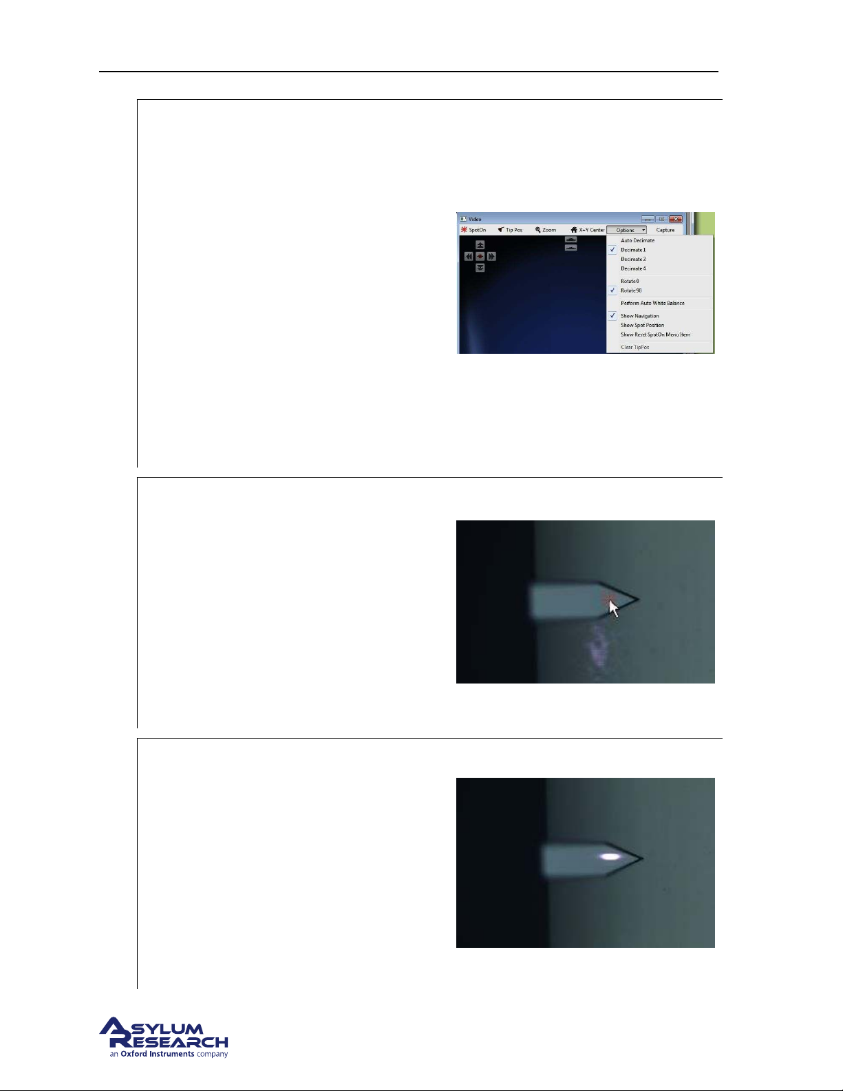
Optional image enhancement and zoom,
particularly useful for small cantilevers:
• If you want to see the image with more
resolution, select Decimate 1 from the
Options pull-down menu. This brings all
the pixels down from the video camera
but will slow the screen update rate.
10.
• To the left of the Options menu is a
‘Zoom’ button. This button, once
clicked, will change the cursor into a
magnifying glass. Click on the
cantilever to get an enlarged view.
• Both of these items may improve your
ability to focus from the previous step.
If you do refocus, be sure to click ‘Set’
next to the ‘Focus on Tip’ button.
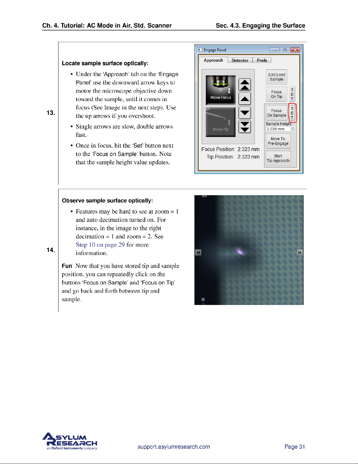
Center laser spot on cantilever:
• Click on the ‘Spot On’ button at the top
left of the video window. The mouse
pointer will acquire some small red
lines.
11.
• Now click on the center of the cantilever
(see figure to right).
• Alternately, right-click on the center of
the cantilever and then select the ‘Spot
On’ option.
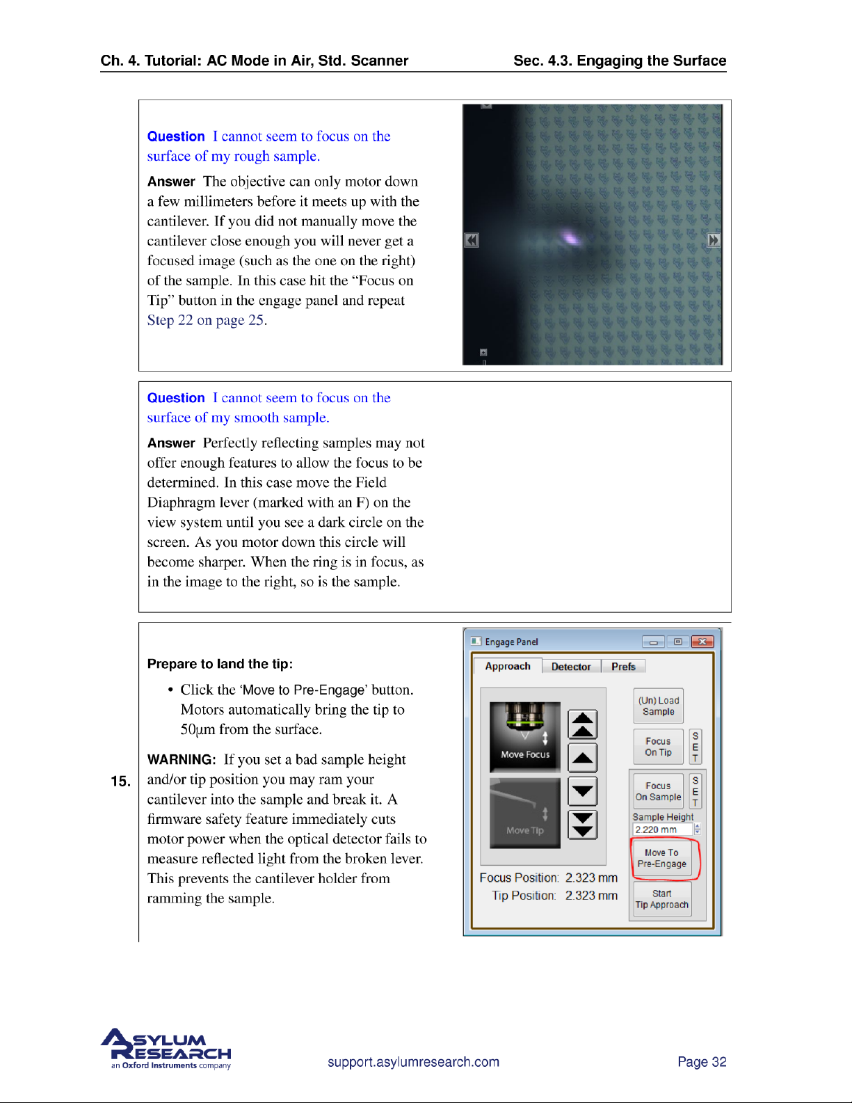
Observe spot on lever:
• Motors inside Cypher will now move to
bring the laser spot where you clicked.
• The spot position does not need to be
12.
perfect here, only roughly centered on
the cantilever to produce a decent
reflected beam (measured by the Sum
signal in the Sum and Deflection Panel).
• If needed, the spot position will be fine
tuned in a later step.
support.asylumresearch.com Page 30
Page 35
Page 36
Page 37
Page 38
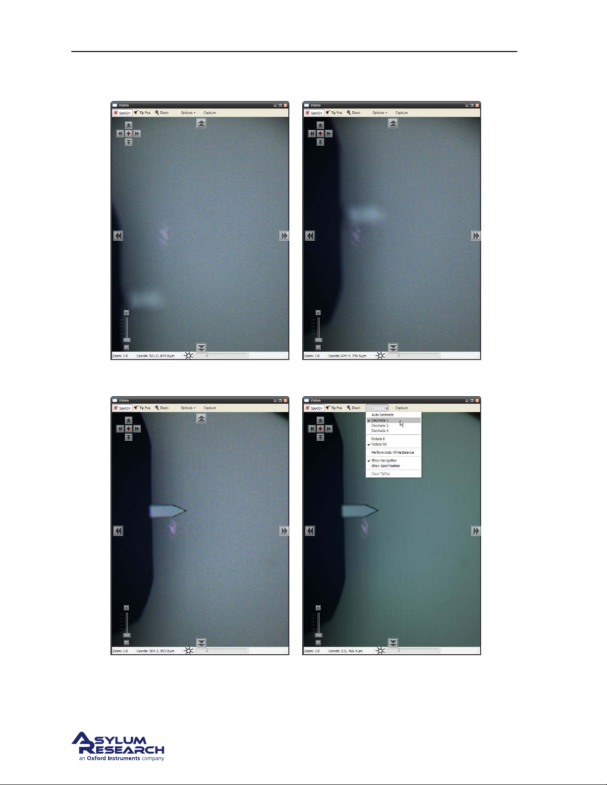
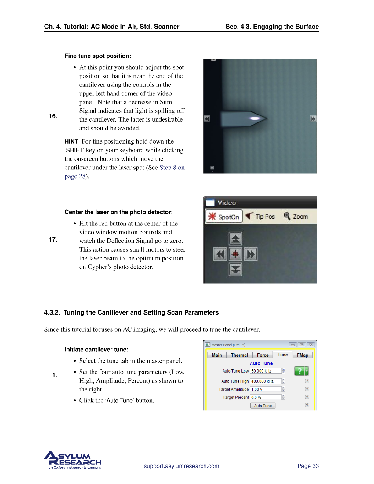
Ch. 4. Tutorial: AC Mode in Air, Std. Scanner Sec. 4.3. Engaging the Surface
(a) First view of new cantilever. (b) Cantilever found and roughly centered on
screen. Step 8 on page 28.
(c) Cantilever in focus. See Step 9 on page 29. (d) Optimize Resolution. See Step 10 on page 29.
Figure 4.1.: Finding the cantilever and optimizing the video.
support.asylumresearch.com Page 34
Page 39
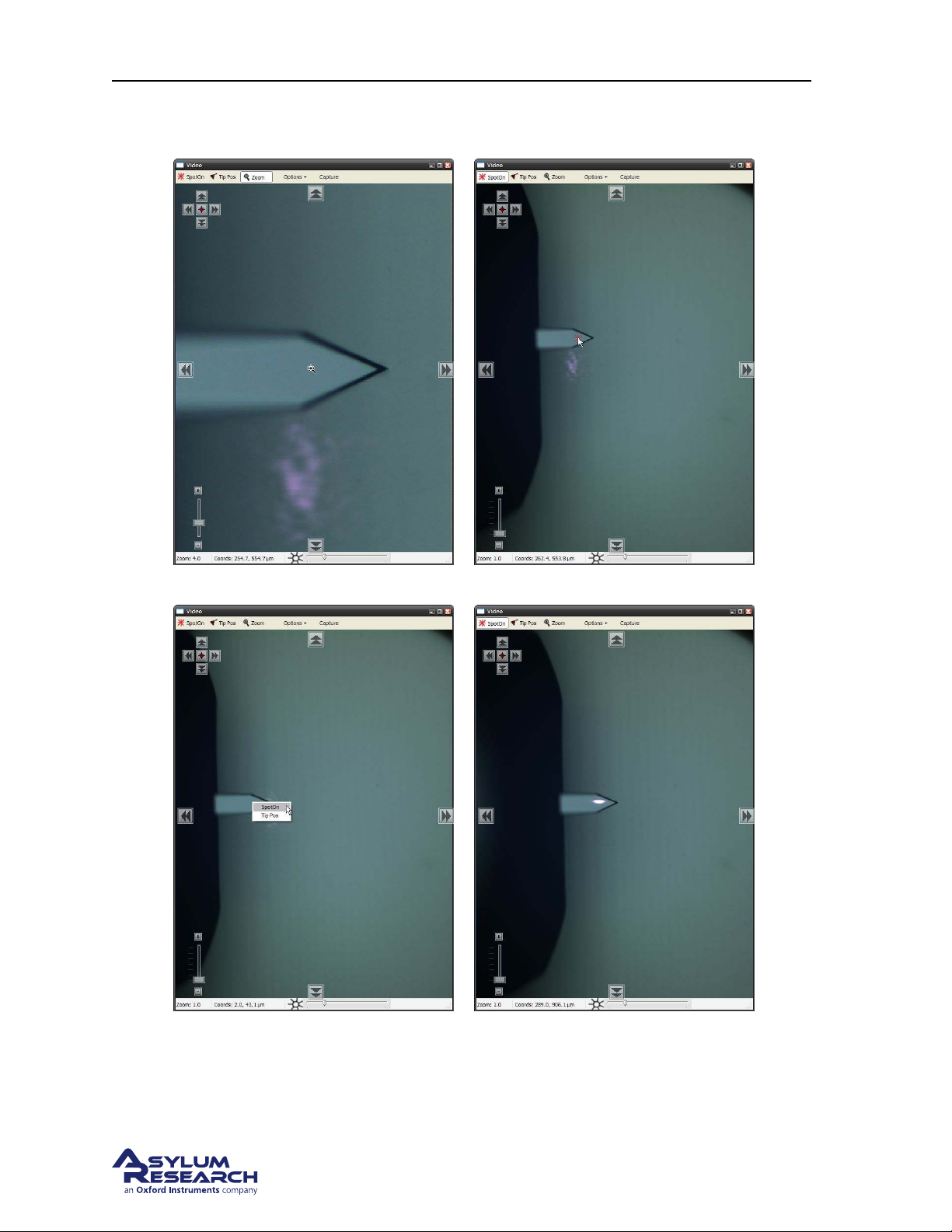
Ch. 4. Tutorial: AC Mode in Air, Std. Scanner Sec. 4.3. Engaging the Surface
(a) Cantilever Zoom. See Step 10 on page 29. (b) Laser Spot ON. See Step 11 on page 30.
(c) Spot On by right clicking. See Step 11 on
(d) Laser spot on the lever. See Step 12 on page 30.
page 30.
Figure 4.2.: Various methods for aligning the laser spot onto the cantilever.
support.asylumresearch.com Page 35
Page 40
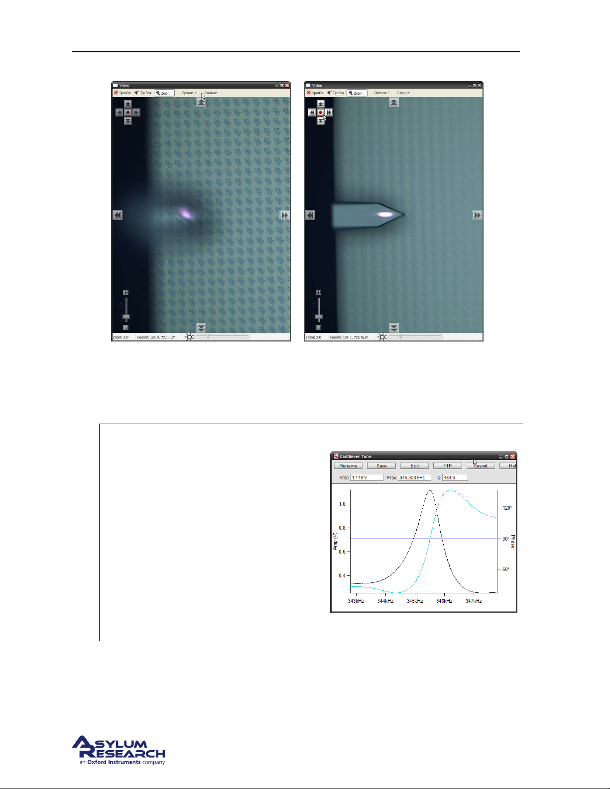
Ch. 4. Tutorial: AC Mode in Air, Std. Scanner Sec. 4.3. Engaging the Surface
(a) Offset. (b) The focus offset is centered and the optical im-
age is confocal with the focused laser spot.
Figure 4.3.: By turning the focus offset knob, it is possible to focus on optical image on the sample while
the laser stays focused on the cantilever.
Observe tune result:
• A graph will pop up with the tune result.
• The resonance curve should peak
around 300kHz.
• The relevant results are automatically
2.
stored. After inspecting that the
amplitude and phase curves look
“clean”, you can close the graph.
HINT Cleaner tunes can be obtained by
blowing the cantilever holder with clean
compressed air prior to loading cantilever to
get rid of any left over silicon/glass debris.
support.asylumresearch.com Page 36
Page 41
Page 42
Page 43
Page 44
Ch. 4. Tutorial: AC Mode in Air, Std. Scanner Sec. 4.4. Imaging
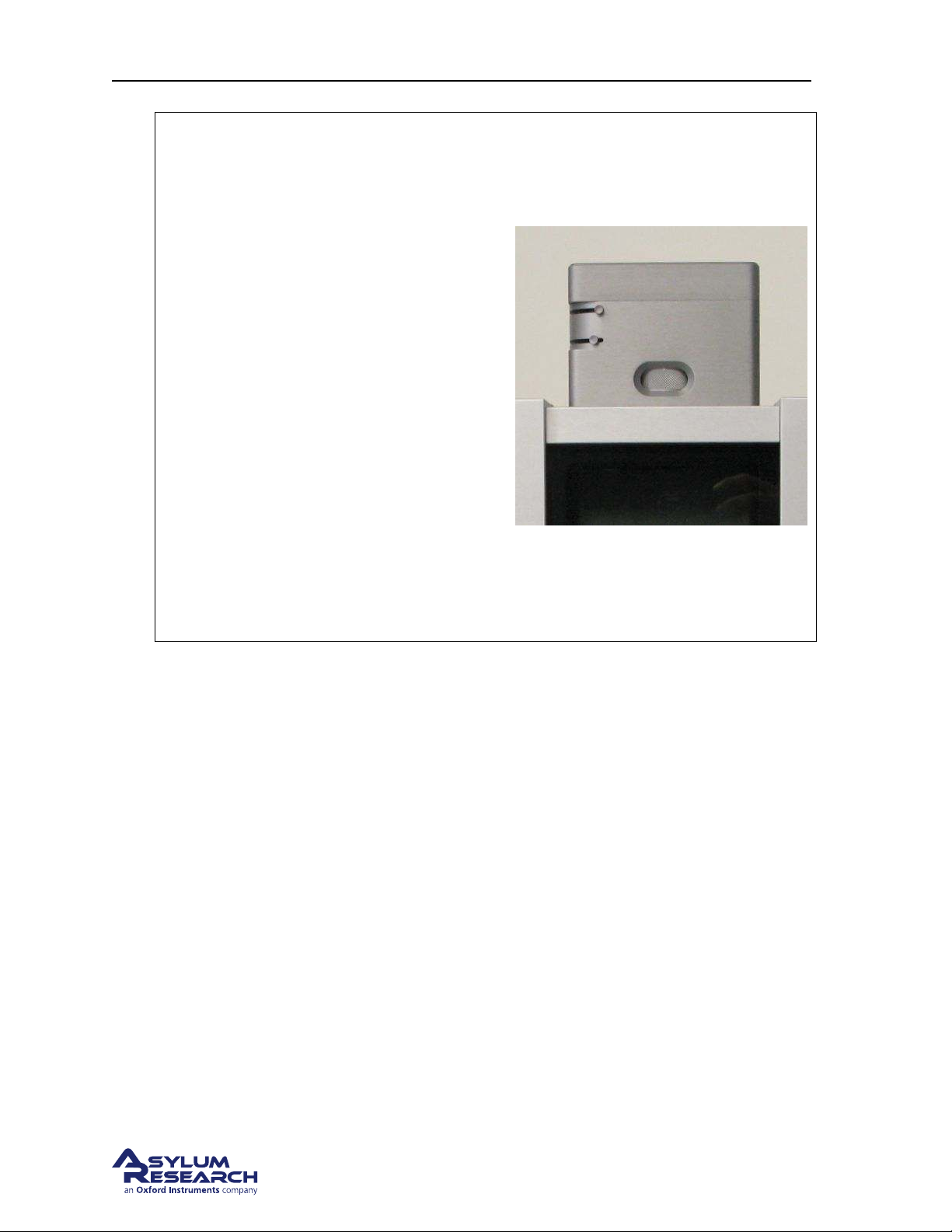
Question Why does the sample look out of
focus when the tip is on the surface? How do
I fix this?
Answer The laser and video image both pass
through the same microscope objective.
While performing AFM, the objective must
remain focused on the back of the cantilever
to keep the laser focused. Since the sample
sits one tip height farther away, it will not be
in focus. The fix is extra optics just before the
video camera. Adjust the focus ring (at the
center in the photo on the right) on the view
system until the sample is in focus. Of course
the cantilever and laser spot will now appear
blurred in the video image.
Note When it comes to focusing on the next
cantilever (
Step 9 on page 29) you must be
sure to set the focus adjustment back to zero,
as in
Step 3 on page 26. Cypher includes a
sensor to see that this has occurred and the
software will warn you to zero the focus
offset when necessary.
4.4. Imaging
This section will get you scanning and tracking the surface.
4.4.1. Set-Up and Initial Parameter Selection
Based on the previous section, it is assumed that:
• The cantilever tip is on the surface, or was just disengaged from the surface.
• The laser is aligned on the cantilever and the photo detector difference (deflection) signal has been
zeroed.
support.asylumresearch.com Page 40
Page 45
Page 46
Ch. 4. Tutorial: AC Mode in Air, Std. Scanner Sec. 4.4. Imaging
4.4.2. Start Imaging and Parameter Tuning
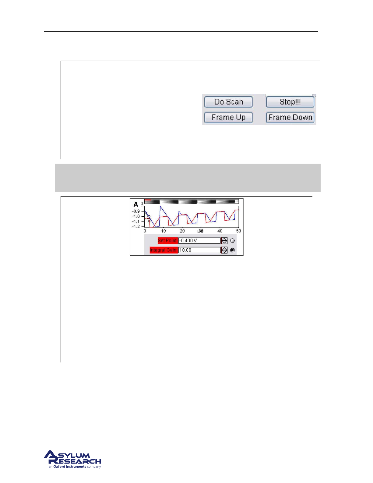
• Click the ‘Do Scan’ button on the ‘Main’
tab of the ‘Master Panel’, and imaging
will begin after a moment. Scan
initiation first moves the tip to the
starting point of the image, then lowers
1.
the tip onto the surface, and then begins
an endless series of image scans. The
red cursor to the left of each image
window indicates the scan line/ location
of the tip.
Tip
Determining Image Quality:
2.
• Start the learning process on a sample with a known topography, like the Asylum
To enhance contrast on the image display, click and drag a box around the
area of interest. Then right click and select fix scale.
Research Calibration Grating being used in this tutorial.
• Look at the ’Scope Trace’ below the image. This graph represents the most recent line
of the image. Blue indicates the tip moving left to right (a.k.a trace) and Red indicates
tip returning from right to left (a.k.a retrace ).
On most samples with relatively slowly changing features, trace and retrace should look the
same. In other words, the landscape should look the same if you are flying the exact same
route one way or the reverse. The image above shows the two as being quite different; this
is an indication that imaging parameters need to be adjusted.
support.asylumresearch.com Page 42
Page 47

Ch. 4. Tutorial: AC Mode in Air, Std. Scanner Sec. 4.4. Imaging
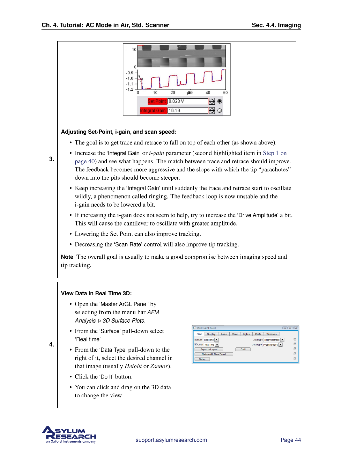
In the previous image the tip is not following the surface. As the blue trace
shows (left to right), the tip seems to climb up out of the pits of the
calibration grating quite nicely (the left edge of each pit is quite sharp) but
then it descends back into the next pit along a relatively gentle slope. During
Nomenclature
this descent the tip actually “flies through the air” while it is completely
un-deflected, a bit like a hang glider running off a cliff. The lateral motion of
the tip simply marches on as dictated by the XY scan pattern. The feedback
control algorithm is simply not aggressive enough to bring the tip back down
to the bottom of the pit. Such behavior is commonly called parachuting or
poor tracking.
The next steps will go into the details of strategies for tuning parameters in
the main panel. Use the arrow clickers (to right of variable fields) to adjust
parameters, rather than typing the values in. Alternatively, you can fine-tune
the parameters using the ‘Hamster’ wheel on the front of the controller. Any
parameter with a radio button next to it can be changed during a scan when it
Hamster
is activated (looks like black/ green dot in circle) with the ‘Hamster’. The
Hamster gives "digital control with analog feel". On the MFP-3D AFM
controller the toggle switch to the left of the ‘Hamster’ allows you to toggle
between radio buttons in the panel. On the ARC2 SPM controller the outer
‘Hamster’ ring performs this function. This tactile experience lets you
concentrate on the image while tuning parameters.
support.asylumresearch.com Page 43
Page 48
Page 49

Ch. 4. Tutorial: AC Mode in Air, Std. Scanner Sec. 4.4. Imaging
Moving the Sample Between Scans:
• Sometimes, it is desirable to move to another point of interest after some scans have been taken.
For features within 12.5 microns, use the X Offset and Y Offset fields. Note that a negative is to
the left or below the initial area.
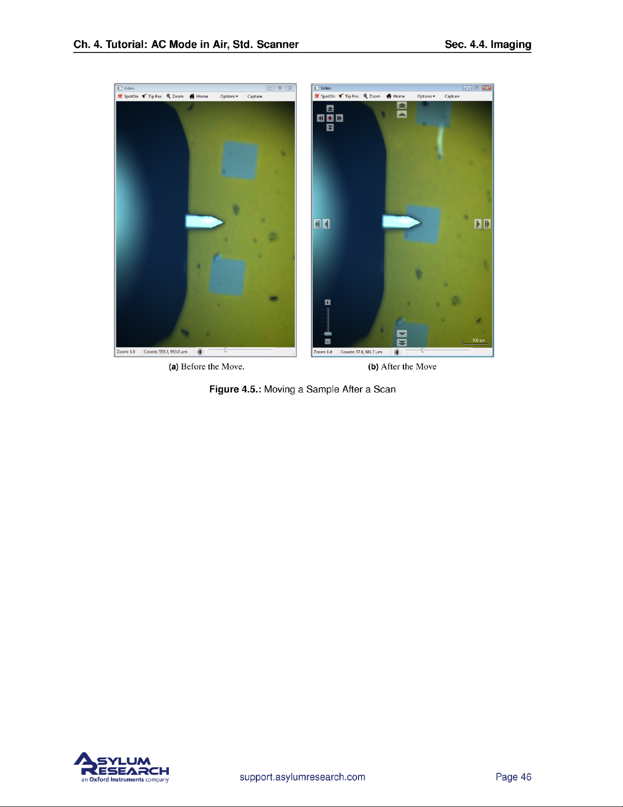
• For features that are further away, use the arrows toward the edges of the Video Panel. The single
arrows are slow, and the double arrows are fast. It is also possible to click and hold the double
arrows for faster, continuous movement. See
Figure 4.5 on page 46 for an example of sample
movement.
Note These buttons move the sample rather than the cantilever, and so the laser and objective stay in
alignment. Be sure to avoid accidentally moving the tip, and remember that the smaller arrow buttons
in the upper left hand corner of the Video Panel are set to the cantilever rather than to the sample.
Q When I make changes to scanning parameters, when do those changes take effect in the scanned
image?
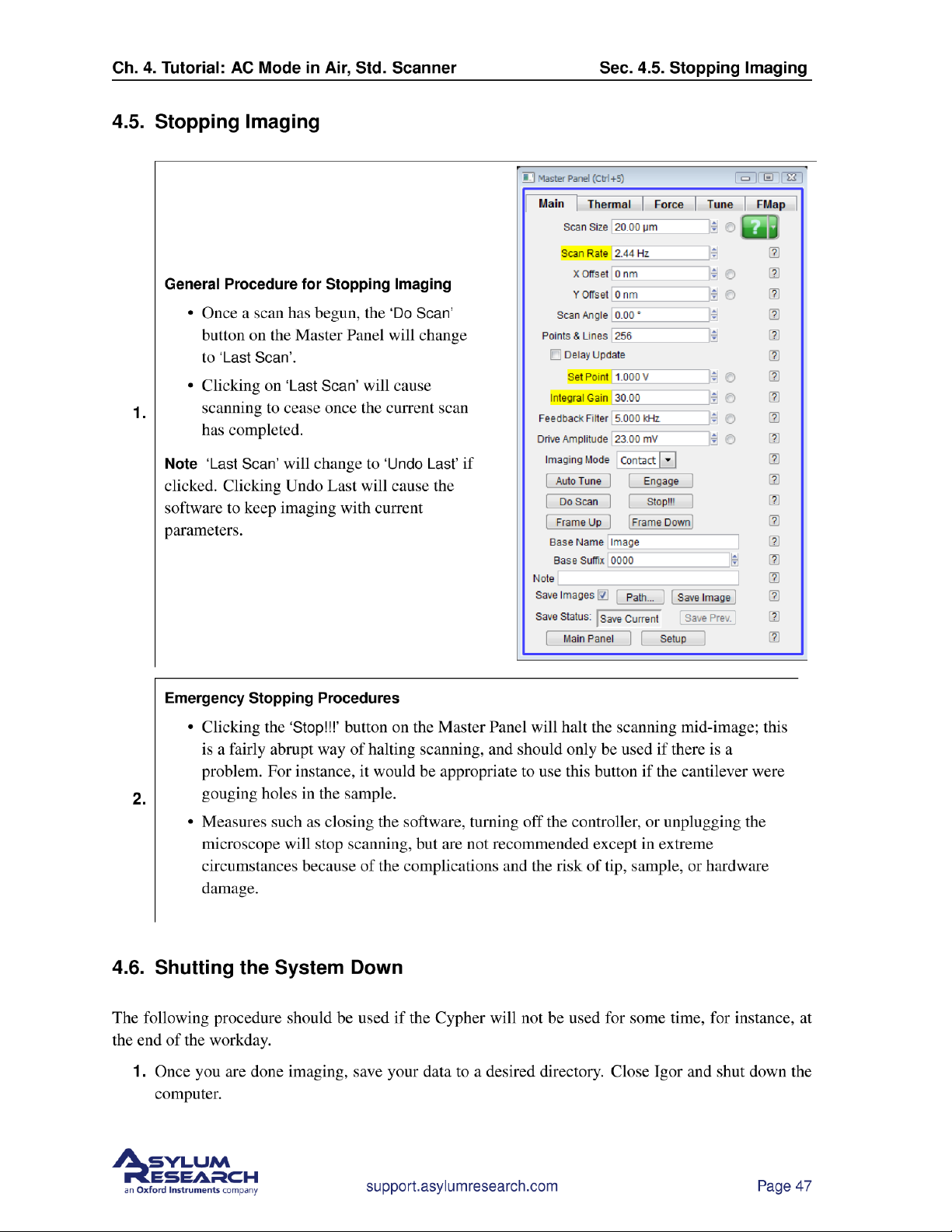
A Most parameters in the main tab of the main panel (See 1) will update as soon as you make a
change. Note that changing points, lines, or scan rate, will tak effect next frame.
If you check the ‘Delay Update’ box just above the ‘Setpoint’ parameter, then any changes you
make to parameters above that box will only update next frame. Until the image is complete,
the changed variables are highlighted in blue.
You can always force a new image by clicking ‘Frame Up’ or ‘Frame Down’. A nice way to see
the effect of changing imaging parameters can be as follows:
• Check the ‘Delay Update’ box as described above.
• Click ‘Frame Up’ and collect a dozen scan lines. Observe the image quality
• Make some changes to the scan parameters (number of points, rate, gains, setpoint).
• Click ‘Frame Up’ again.
• Observe as the exact same scan region is ”painted over” with new data taken with your new
parameter choices.
4.4.3. Image Refinement
To learn more about using the Asylum Research SPM software to refine your imaging parameters, please
refer to Applications Guide, Chapter: AC Mode Imaging in Air and also MFP-3D User Guide, Chapter:
Tutorial: AC Mode Imaging in Air. Also consider watching this introductory video: AC Mode Imaging
(requires an internet connection).
in Air
support.asylumresearch.com Page 45
Page 50
Page 51
Page 52

Ch. 4. Tutorial: AC Mode in Air, Std. Scanner Sec. 4.6. Shutting the System Down
2. The tip will disengage automatically when imaging stops, but for added safety, motor the tip away
from the sample. You may want to remove the sample at this point.
3. Turn off the laser key on the controller.
4. Power off the controller.
support.asylumresearch.com Page 48
Page 53

Ch. 5. Cantilever Holder Guide
5. Cantilever Holder Guide
CH AP TE R REV. 1710, DATED 10/23/2013, 21:54. US ER GUIDE REV. 1714, DATED 10/25/2013, 20:36.
Chapter Contents
5.1 Identifying Cantilever Holders . . . . . . . . . . . . . . . . . . . . . . . . . . . . . . . . 49
5.1.1 Visual Guide of Cantilever Holders . . . . . . . . . . . . . . . . . . . . . . . . 49
5.1.2 Electronic Identification of Cantilever Holders . . . . . . . . . . . . . . . . . . . 51
5.2 Cantilever Holder Changing Stations . . . . . . . . . . . . . . . . . . . . . . . . . . . . 51
Depending on your specific imaging application the appropriate cantilever holder must be used. This
chapter serves as a guide to the available Standard Scanner options and to help you identify the types of
cantilever holders you may already own.
All the available cantilever holders have many things in common:
• All have a circuit board which allows the system to identify the type of cantilever holder and to
activate the appropriate software control panels.
• Nearly all have a piezoelectric actuator and allow AC mode and contact mode imaging.
• Nearly all have the ability to apply DC and AC voltage to the cantilever.
Many more contain specific electronics allowing for current measurement, application of high voltage
to the tip„ and more.
Cantilever holders are the most delicate components of the AFM. Treat it like you
Be Careful
might treat your great grandfather’s pocket watch. Never drop it. Remember that
even the most basic cantilever holder costs thousands of dollars to replace.
5.1. Identifying Cantilever Holders
5.1.1. Visual Guide of Cantilever Holders
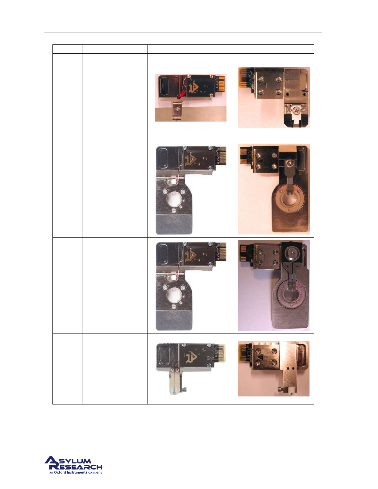
Please use this table to identify your cantilever holders and find the relevant sections which describe
them.
BETA
Page 49
Page 54
Ch. 5. Cantilever Holder Guide Sec. 5.1. Identifying Cantilever Holders
Part # Holder Description Front Photo Back Photo
Air
For most contact and
AC mode Imaging.
It’s use is described
901.705
well in this tutorial:
Section 4.2 on
page 18. Fits in the
Air Changing
Station. For use in
air only.
Droplet*
For fluid imaging in
a droplet. See
901.730
Chapter 6 on
page 53. Fits in the
Droplet Changing
Station. For use in
air or liquid.
901.740
901.727
iDrive*
For
Electromagnetically
Driven imaging, in
air and droplets. See
Chapter 7 on
page 75. Fits in the
Droplet Changing
Station. For use in
air or liquid.
STM
Scanning Tunneling
Microscopy. See
Chapter 9 on
page 103
. Fits in the
Air Changing
Station. For use in
air or liquid.
BETA
Page 50
Page 55
Ch. 5. Cantilever Holder Guide Sec. 5.2. Cantilever Holder Changing Stations
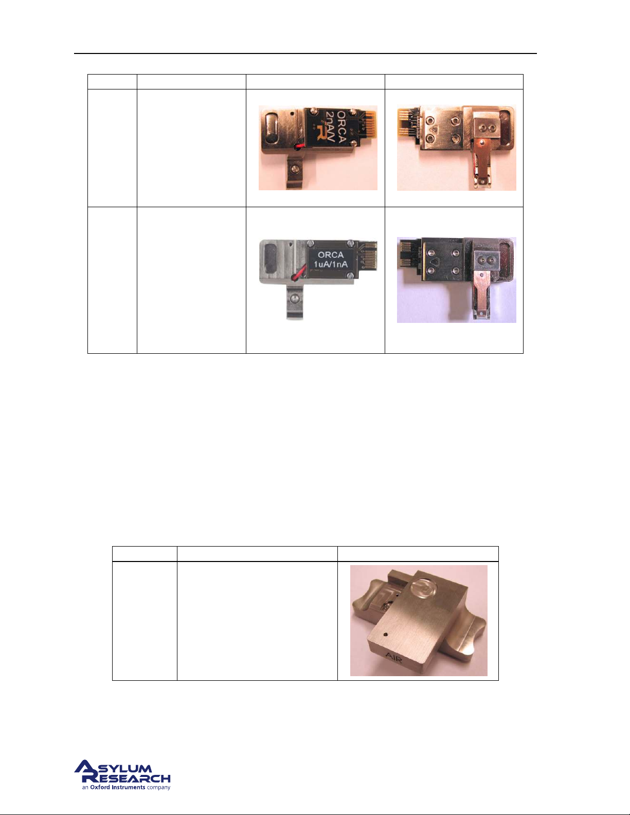
Part # Holder Description Front Photo Back Photo
ORCA
Conductive AFM
with a single current
901.73x
901.708
range. See
on page 92. Fits in
the Air Changing
Station. For use in
air only.
Dual Gain ORCA
Conductive AFM
with a two
simultaneous current
ranges. See
Chapter 8 on
page 92. Fits in the
Air Changing
Station. For use in
air or liquid.
Chapter 8
5.1.2. Electronic Identification of Cantilever Holders
1. Attach the cantilever holder to the Cypher Scanner. (See Step 17 on page 23).
2. From the main menu bar in the software select Programming ⊲ Cantilever Holder and Sample Panel.
3. At the bottom left of this panel click the ‘Check Holder’ button and the type of cantilever holder
will be highlighted.
5.2. Cantilever Holder Changing Stations
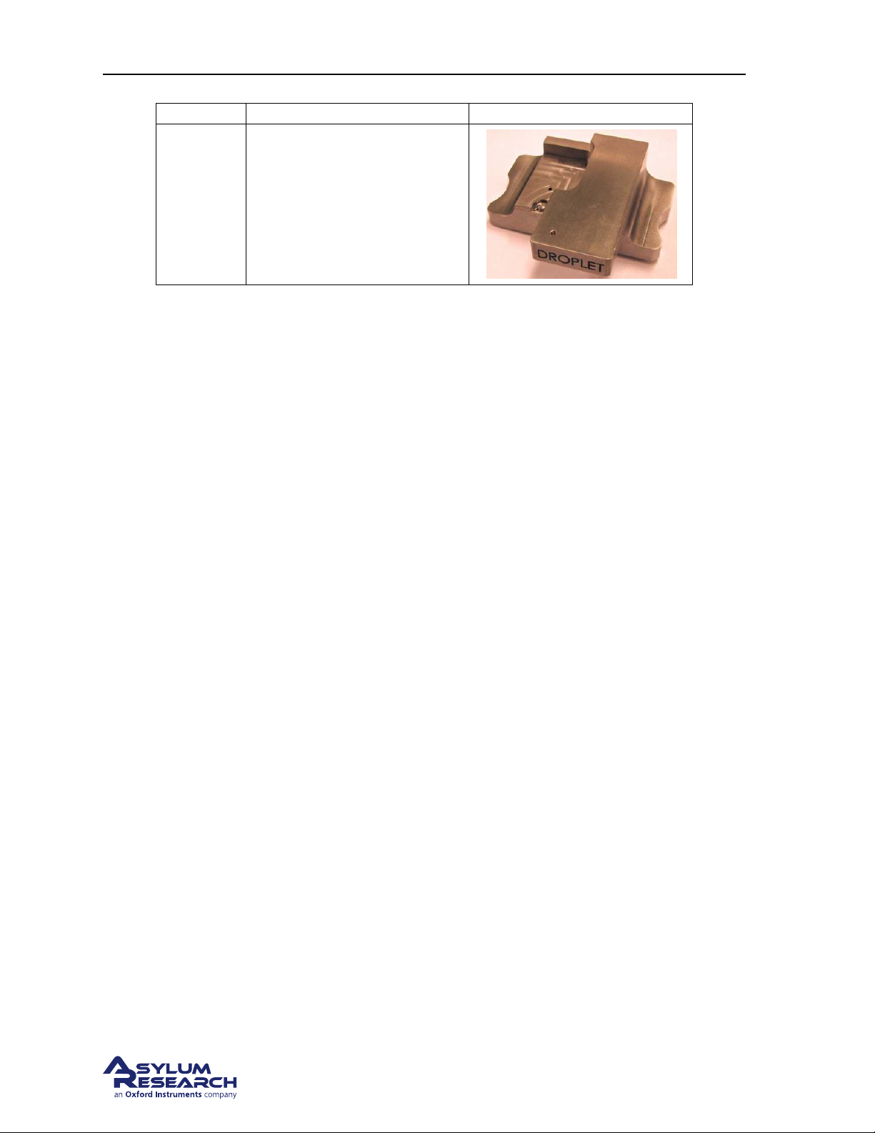
Part # Item Description Picture
Air Cantilever Holder Changing
Station. Used with Cypher
901.715
cantilever holders that look like
the Standard Air Cantilever
Holder.
BETA
Page 51
Page 56
Ch. 5. Cantilever Holder Guide Sec. 5.2. Cantilever Holder Changing Stations
Part # Item Description Picture
Air Cantilever Holder Changing
Station. Used with Cypher
901.716
cantilever holders that look like
the Standard Droplet Cantilever
Holder.
BETA
Page 52
Page 57

Ch. 6. Fluid Imaging in a Droplet
6. Fluid Imaging in a Droplet
CH APTE R R EV. 1710, DATE D 1 0/23/2013, 21:54. US ER GUID E RE V. 1 714, DAT E D 10/25/2013, 20:36.
Chapter Contents
6.1 Nomenclature . . . . . . . . . . . . . . . . . . . . . . . . . . . . . . . . . . . . . . . . 54
6.2 Parts List . . . . . . . . . . . . . . . . . . . . . . . . . . . . . . . . . . . . . . . . . . 54
6.3 Preparing for Imaging . . . . . . . . . . . . . . . . . . . . . . . . . . . . . . . . . . . . 56
6.3.1 Mounting the Sample Dish . . . . . . . . . . . . . . . . . . . . . . . . . . . . 57
6.3.2 Mounting the Cantilever . . . . . . . . . . . . . . . . . . . . . . . . . . . . . . 58
6.3.3 Using the Evaporation Shield . . . . . . . . . . . . . . . . . . . . . . . . . . . 58
6.3.4 Sample Mounting . . . . . . . . . . . . . . . . . . . . . . . . . . . . . . . . . 59
6.3.5 Installing the Cantilever Holder . . . . . . . . . . . . . . . . . . . . . . . . . . 59
6.3.6 Engaging . . . . . . . . . . . . . . . . . . . . . . . . . . . . . . . . . . . . . 61
6.3.6.1 Pre-engage adjustments . . . . . . . . . . . . . . . . . . . . . . . 61
6.3.6.2 Focus on the cantilever . . . . . . . . . . . . . . . . . . . . . . . . 62
6.3.6.3 Focus on the sample . . . . . . . . . . . . . . . . . . . . . . . . . 62
6.4 Imaging with the Droplet Holder . . . . . . . . . . . . . . . . . . . . . . . . . . . . . . 65
6.4.1 AC Mode Tuning Specifics . . . . . . . . . . . . . . . . . . . . . . . . . . . . . 65
6.4.2 Imaging Specifics . . . . . . . . . . . . . . . . . . . . . . . . . . . . . . . . . 67
6.4.2.1 Engaging in fluid in AC mode . . . . . . . . . . . . . . . . . . . . . 67
6.5 Removal and Storage . . . . . . . . . . . . . . . . . . . . . . . . . . . . . . . . . . . . 69
6.5.1 Removing the Dish . . . . . . . . . . . . . . . . . . . . . . . . . . . . . . . . 69
6.5.2 Storage . . . . . . . . . . . . . . . . . . . . . . . . . . . . . . . . . . . . . . 69
6.6 Cleaning and Repair . . . . . . . . . . . . . . . . . . . . . . . . . . . . . . . . . . . . 69
6.6.1 Disassembly . . . . . . . . . . . . . . . . . . . . . . . . . . . . . . . . . . . . 69
6.6.2 Cleaning . . . . . . . . . . . . . . . . . . . . . . . . . . . . . . . . . . . . . . 72
6.6.3 Reassembly . . . . . . . . . . . . . . . . . . . . . . . . . . . . . . . . . . . . 72
6.6.4 Adjusting Piezo Preload . . . . . . . . . . . . . . . . . . . . . . . . . . . . . . 73
6.6.4.1 Finishing up . . . . . . . . . . . . . . . . . . . . . . . . . . . . . . 74
This chapter explains the use of the droplet cantilever holder designed for use with the Cypher Scanner.
In this design, the sample is such that the scanning area is submerged in small volume of water (typically
around 100uL) which encapsulates both the scanning area and the cantilever. The water environment is
maintained by the meniscus bridge formed between the sample substrate and the underside of the glass
window of the droplet holder.
Liquids other than water are not recommended. Volatile solvents may fill the Cypher enclosure with
damaging or harmful vapors. The membrane is made of silicone and was not designed for a high level
of chemical resistance.
BETA
Page 53
Page 58
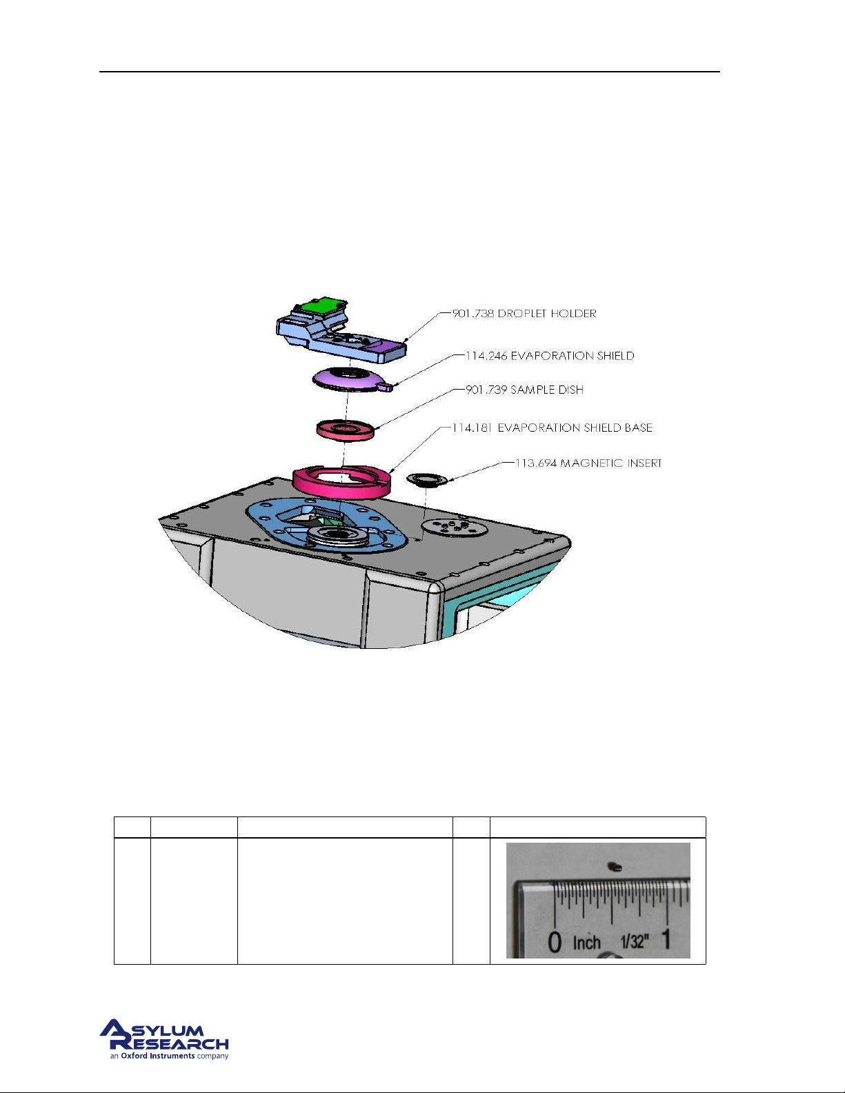
Ch. 6. Fluid Imaging in a Droplet Sec. 6.1. Nomenclature
The cantilever holder can be used for contact mode and AC mode imaging in fluid. It has a built-in
piezoelectric actuator for driving cantilevers at resonance. Please refer to Chapter 7 on page 75 for
specifics on iDrive imaging only.
6.1. Nomenclature
Please refer to
Figure 6.1 on page 54.
Figure 6.1.: Droplet Cantilever Holder nomenclature.
6.2. Parts List
Asylum Inventory Number 901.738.1
Itm Part # Item Description Qty Picture
004. SETS
1
<#80 x
0.063>
CUP
0-80 x 1/16” set screw, cup
point.
6
BETA
Page 54
Page 59
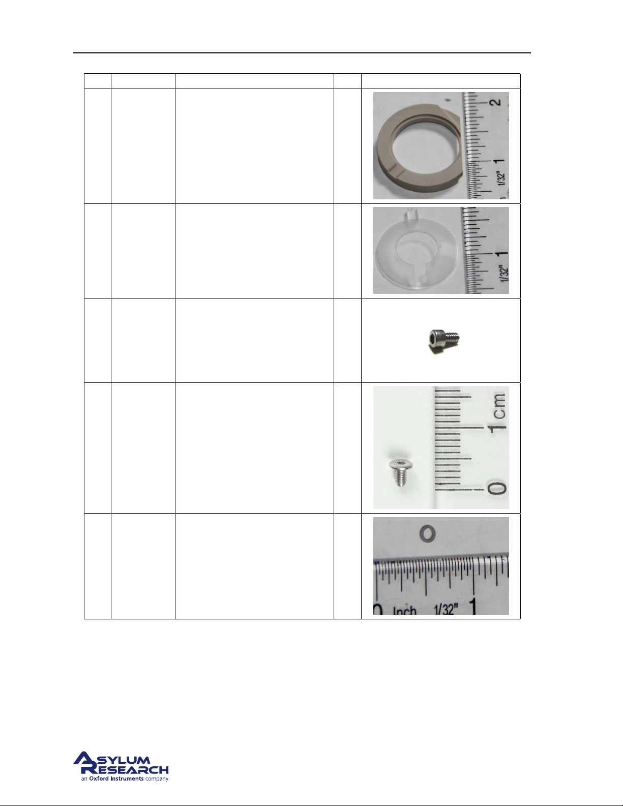
Ch. 6. Fluid Imaging in a Droplet Sec. 6.2. Parts List
Itm Part # Item Description Qty Picture
2 114.181 Ring, Gasket Base 1
3 114.246 Shield, Low Profile Evaporation. 3
4 222.070
5 222.072 Screw, M2 X 4, Stainless. 5
6 222.094
Socket Head Cap Screw, 0-80 X
7/64”
Washer, 0.157” x 0.096” x
0.010” 17-7 stainless steel.
12
5
BETA
Page 55
Page 60
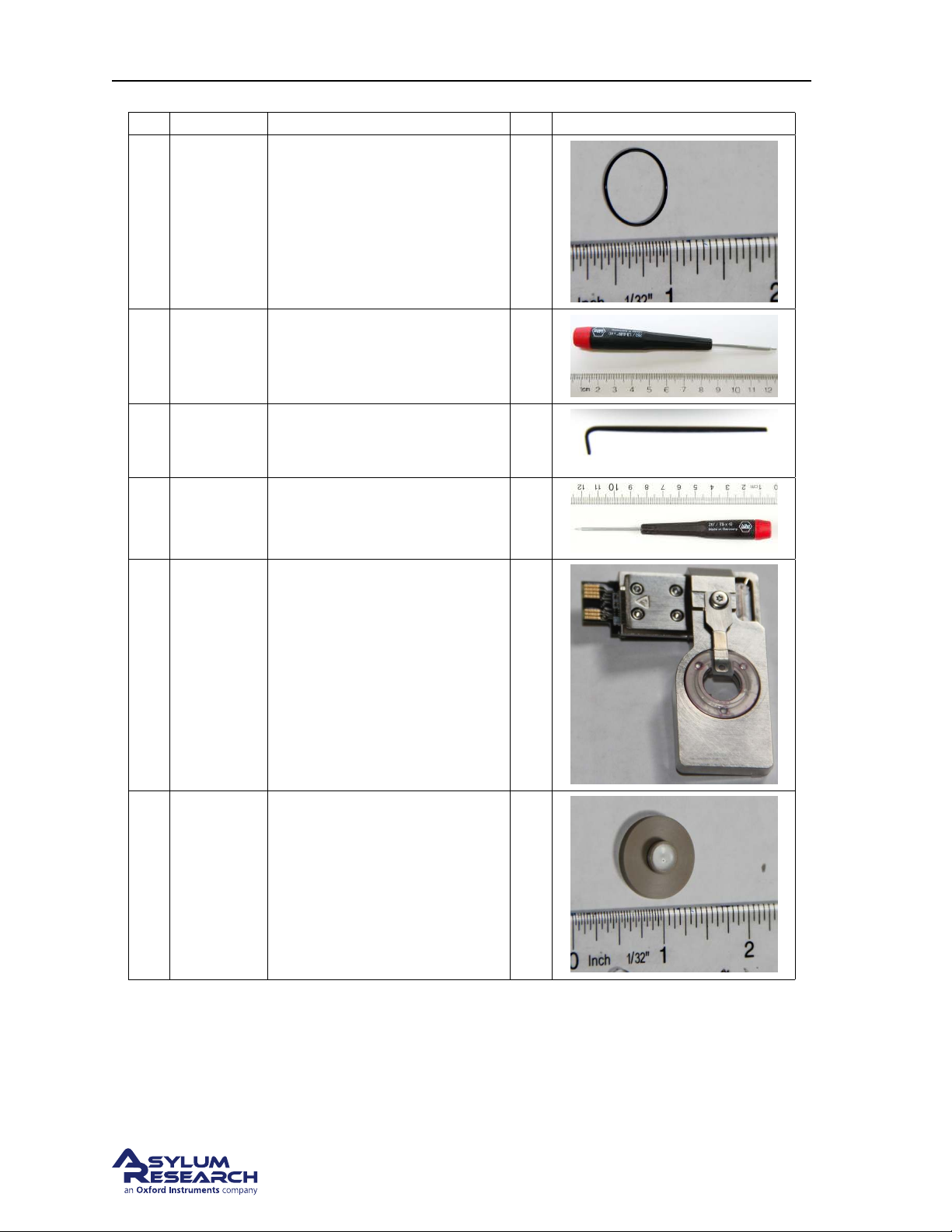
Ch. 6. Fluid Imaging in a Droplet Sec. 6.3. Preparing for Imaging
Itm Part # Item Description Qty Picture
7 230.035
8 290.111
9 290.136 Short arm hex key, 0.028”. 1
10 290.144 T5 2.5MM Torx Driver. 1
O-ring, 0.551” x 0.022”, 60
Durometer FKM.
0.050”: Wiha Allen Driver 263
1,3 – 0.05” X 40.
2
1
11 901.738
12 901.739
Cypher Droplet Holder
Assembly, V2.
Small Diameter Droplet Holder
Cup Assembly.
6.3. Preparing for Imaging
Before you start:
1
1
• We assume you understand the aspects of running this system safely: (Chapter 20 on page 229.)
BETA
Page 56
Page 61
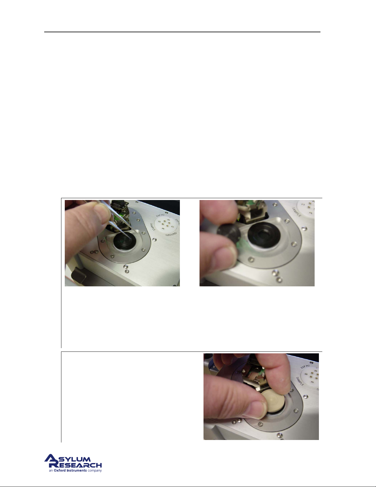
Ch. 6. Fluid Imaging in a Droplet Sec. 6.3. Preparing for Imaging
• You are familiar with the basic names of the hardware components and software controls (Chap-
ter 1 on page 3.)
• You have powered up the Cypher and launched the software: (
• You are comfortable with AC Mode Imaging in Air, as instructed by the tutorial: (
page 17
6.3.1. Mounting the Sample Dish
The sample dish was originally integral to the evaporation control in an earlier droplet holder design
where an evaporation shield attached to the droplet holder. This scheme was difficult to use so the
evaporation control components were redesigned as is now described. The sample dish is now only
used to catch fluid overflow.
Fluid scanning experiments can be carried out with or without the use of the sample dish since in either
case the fluid should be confined between the glass of the droplet holder and the sample. The dish is not
intended to be used as a reservoir for liquids. To install the sample dish remove the magnetic insert in
the scanner cap and thread the dish into the scanner.
1.
).
Chapter 2 on page 10.)
Chapter 4 on
Remove the magnetic insert
• Use a tool like the point of a pair of tweezers to fit into one of the holes in the insert.
• Push the insert counter clockwise to loosen the threads.
• Remove the insert and store in a safe place.
Install the Sample Dish
2.
• Thread the dish into the scanner cap and
gently tighten.
BETA
Page 57
Page 62
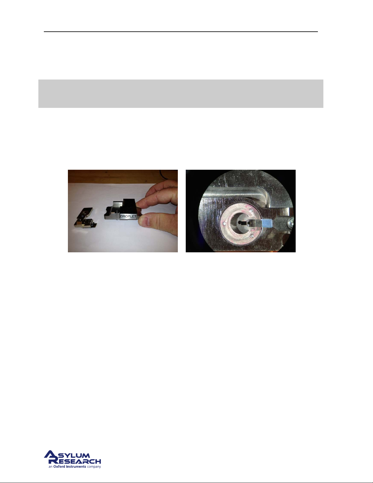
Ch. 6. Fluid Imaging in a Droplet Sec. 6.3. Preparing for Imaging
6.3.2. Mounting the Cantilever
This cantilever holder requires the 901.716 droplet changing station (See Figure 6.2a on page 58).
Warning
Using the wrong changing station will not work and may damage your cantilever
holder.
Once you have located the changing station, the procedure is the same as you are probably familiar
with from AC mode imaging in Air. If you are not familiar with this you should seriously consider
following the tutorial in
is described in
Step 9 on page 21 through Step 14 on page 22.
When finished your aligned cantilever should look like
(a) Droplet Cantilever Holder Changing Station
XXX.XXX. Notice the markings.
Chapter 4 on page 17 at least once. Herein the specifics of mounting cantilevers
Figure 6.2b on page 58.
(b) Properly centered cantilever in the Droplet
Cantilever Holder.
Figure 6.2.
6.3.3. Using the Evaporation Shield
Since the volume of liquid is small, evaporation will limit the experiment time to about 30 minutes. It
is possible to extend the experiment without disengaging the tip by adding liquid into the gap between
the sample and the droplet holder from the side by using a pipette.
The droplet holder is supplied with a set of parts which will allow you to build a semi enclosed chamber to help reduce the rate of evaporation. With the evaporation control in place, the typical time of
the experiment can be extended about three times compared to scanning without them. Basically, the
evaporation shield surrounds the scanning area while contacting the underside of the droplet holder
window.
The current design of the evaporation base is sized to work with or without the sample dish using a
sheet of mica or a glass cover slip mounted to a steel puck. Thicker bases can be provided if your
typical specimen thickness prevents the shield from contacting the holder.
BETA
Page 58
Page 63
Ch. 6. Fluid Imaging in a Droplet Sec. 6.3. Preparing for Imaging
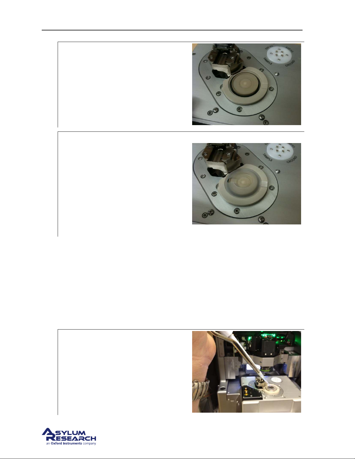
Install the evaporation shield base
• Place the base into the recess around the
1.
sample stage
Note: The top of the base has a lip where the
evaporation shield fits.
Install the evaporation shield
• Place your sample onto the scanner.
• Place the evaporation shield on the base.
2.
submerge the sample
Note: The tab on the shield makes a nice
handle to allow you to manipulate it into
position. Use tweezers to fit the bottom edge
of the shield into the groove on the base.
• Add a drop (approx. 100uL) of liquid to
6.3.4. Sample Mounting
Typically a sample is mounted directly to a steel AFM puck as you would for air imaging. The sample
should be large enough to allow a drop of liquid to be placed on it. If the specimen is a material which
requires a substrate, a piece of mica or a 15mm glass cover slip should be epoxied to the steel puck.
6.3.5. Installing the Cantilever Holder
1. Install the appropriate cantilever for your experiment.
Immerse the sample:
• Add a drop of liquid (approx. 100uL)
2.
onto the sample surface.
• A laboratory pipette is recommended to
deliver the liquid.
BETA
Page 59
Page 64
Ch. 6. Fluid Imaging in a Droplet Sec. 6.3. Preparing for Imaging
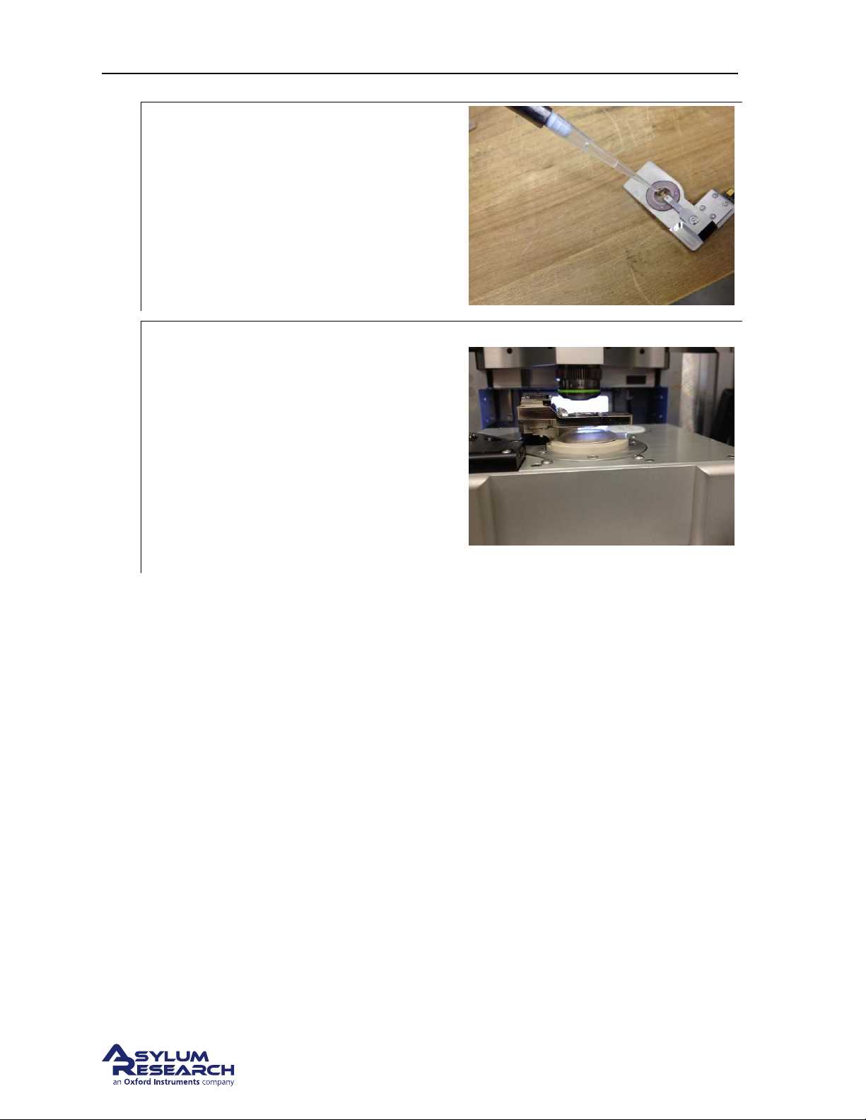
Wet the cantilever:
• Add a small drop of liquid to the
3.
4.
window of the droplet holder to
submerge the cantilever.
• This prevents bubbles and unwanted
bending of very soft levers.
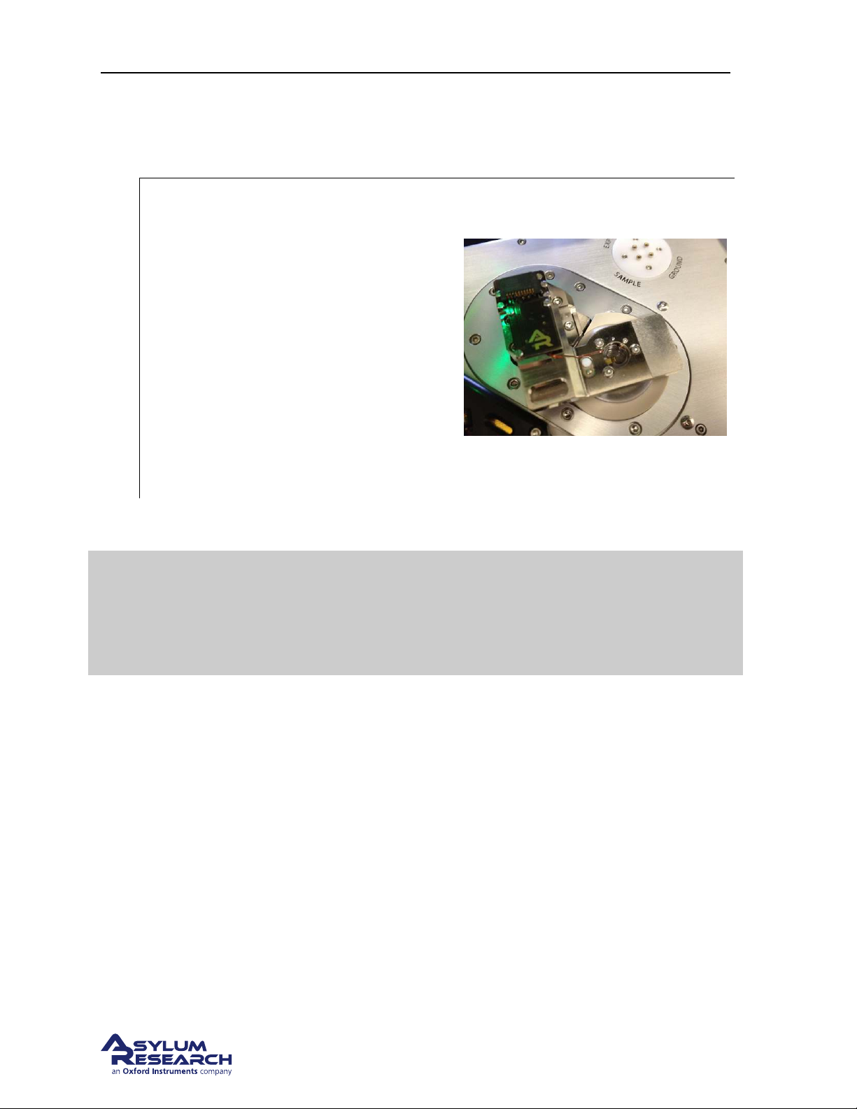
Mount the cantilever holder:
• Fit the droplet holder into the dovetail
socket on the scanner as you would for
the air cantilever holder (see
page 23)
• If necessary, use the coarse approach
wheel on the front of the enclosure to
raise the cantilever holder pillar high
enough to clear the evaporation shield if
it’s installed.
Step 17 on
5. Secure the droplet holder to the engage pillar by tightening the dovetail clamp. Remember to only
hold the driver tool with your fingertips and gently tighten the screw.
BETA
Page 60
Page 65
Ch. 6. Fluid Imaging in a Droplet Sec. 6.3. Preparing for Imaging
6.3.6. Engaging
6.3.6.1. Pre-engage adjustments
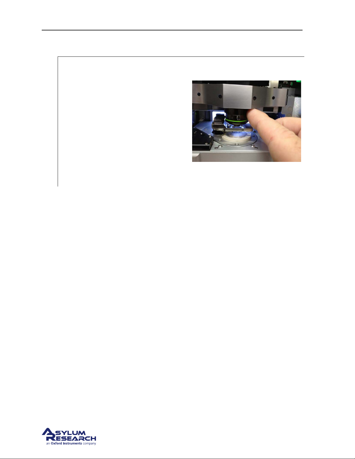
Coarse Engage:
• Pull the scanner forward.
• Using the control wheel on the
instrument base, slowly lower the holder
toward the sample.
• Look down through the glass window
1.
and watch for the moment it contacts
the liquid. You will notice the drop on
the window will disappear and the view
through the glass becomes slightly
darkened.
• Stop lowering the holder when this
happens.
2. Push the scanner into the chassis and close the scanner clamp on the chassis.
The droplet holder is designed to work only in fluids. Do not try to engage the tip
in air. The software automatically compensates for the refractive index of water.
Warning
Focusing on the tip and sample in air will cause the actual distances to be incorrect
and the cantilever will crash into the sample. This feature can be disabled but for
general usage, please only focus the optics through water.
BETA
Page 61
Page 66
Ch. 6. Fluid Imaging in a Droplet Sec. 6.3. Preparing for Imaging
6.3.6.2. Focus on the cantilever
Adjust objective focus ring:
• Move the focus offset ring on the
objective to the 2mm position. This is
necessary in order to compensate for the
change in focal depth of the objective
focusing through the glass window and
1.
liquid.
Note: Moving the focus offset ring to 2mm is
important to correctly focus the instrument’s
optics. The system requires correctly
knowing the tip and sample focus in order to
avoid the tip crashing into the sample and for
proper deflection detection.
2. Focus on the cantilever as you would normally do for air imaging, outlined in more detail in 4.3.
We assume you are familiar with that tutorial and will only cover the main points briefly.
3. Set the cantilever focus position.
4. Use Spot On to move the cantilever under the AFM light spot.
5. Zero the deflection voltage.
Note: On occasion, an air bubble may get trapped between the glass window and the cantilever. If this
has happened, raise the droplet holder out of the liquid and lower it back into coarse position over the
sample. If the bubble is still there you may need to remove the droplet holder, suck off any liquid on the
window and reapply a fresh drop to the cantilever area.
6.3.6.3. Focus on the sample
1. Lower the objective until features on the sample surface come into focus.
2. Set the sample focus position.
3. Click on the ’Move to Pre-Engage’ button.
4. Make any adjustments to the AFM spot or the deflection voltage before engaging the tip.
Using the Field Diaphragm to focus on transparent samples
In cases where there is nothing to focus on because the specimen is featureless and the substrate is
transparent, you can focus on the edge of field diaphragm which typically comes into focus about 30µm
above the actual sample surface.
Being familiar with this method takes a little practice but once you know what visual ques to look for, it
becomes relatively easy.
BETA
Page 62
Page 67
Ch. 6. Fluid Imaging in a Droplet Sec. 6.3. Preparing for Imaging
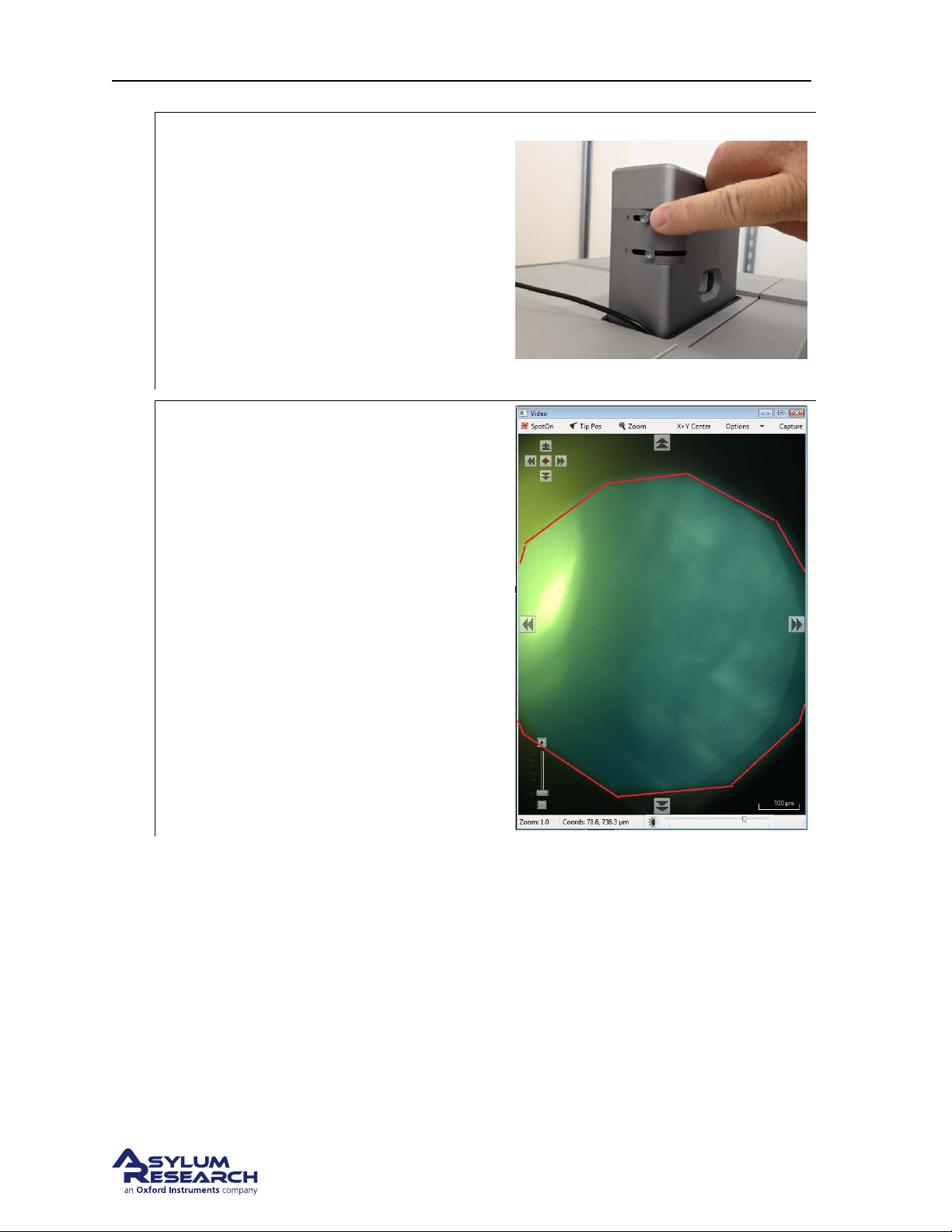
Adjust the aperture diaphragm:
• Adjust the Aperture Diaphragm lever (
labeled A) on the View Module to
reduce the illumination by about 90%.
1.
2.
• In the software, increase the
illumination brightness to compensate
for the reduction of light. This will help
increase the image contrast and in many
cases this is enough to see fine surface
details.
Adjust the aperture diaphragm:
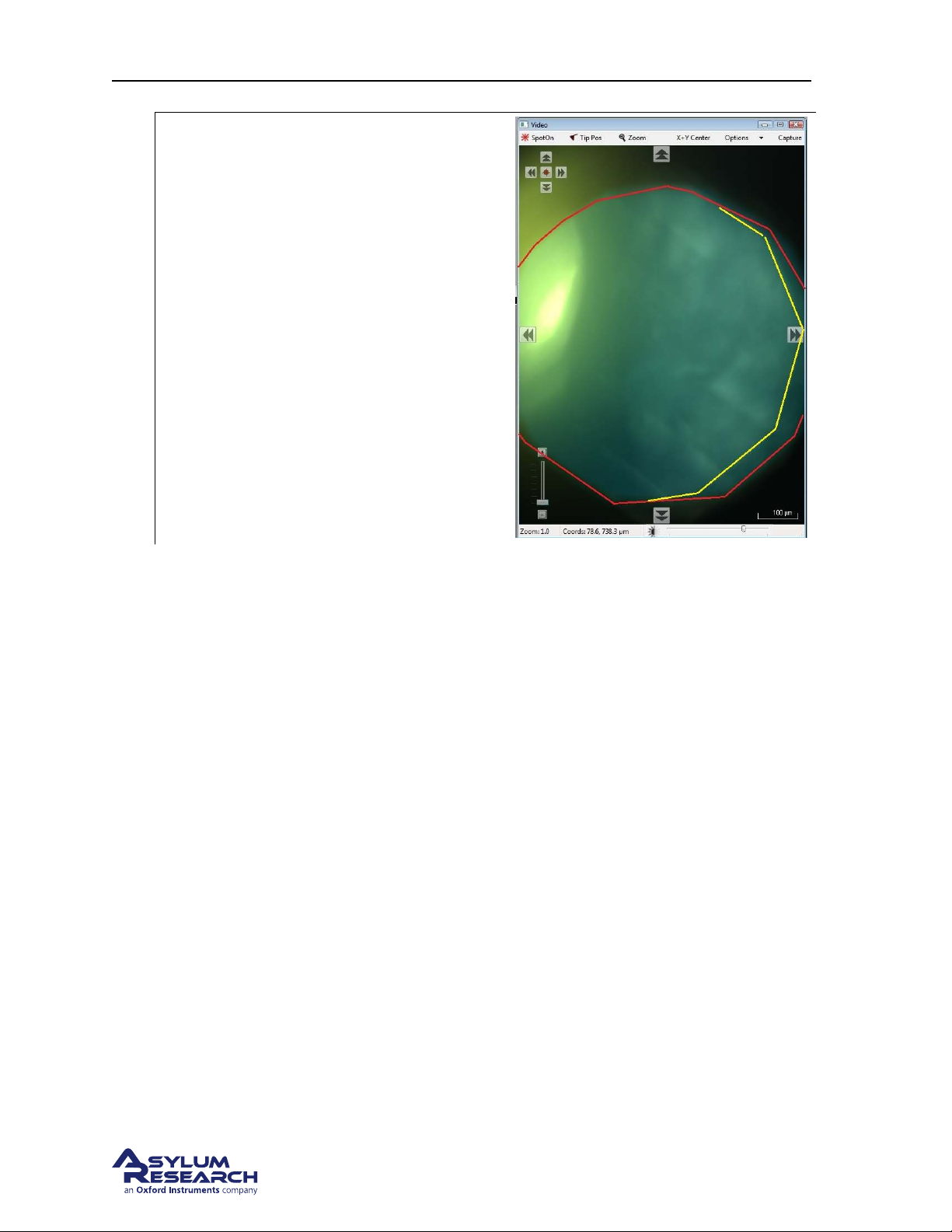
• Adjust the Field Diaphragm lever
(labeled F) on the view module until the
edge of the aperture comes into view in
the video image.
BETA
Page 63
Page 68
Ch. 6. Fluid Imaging in a Droplet Sec. 6.3. Preparing for Imaging
Lower the objective:
• Lower the objective while watching for
the surface to come into focus.
• As you lower the objective, you will
first see the edge of the field diaphragm
3.
come into focus.
• Once the field diaphragm is in focus,
slowly continue to lower the objective.
Look for subtle structures like the edge
of a layer of mica or a small bits of
debris. This is most likely the sample
surface.
4. One way to confirm this is to note the focus position distance located just below the arrow buttons.
Raise the objective back up to focus on the field diaphragm and note how much the focus distance
has changed. Typically, the sample focus distance is about 30µm below the focus distance of the
field diaphragm.
Note You may see that the edge of the field diaphragm is shifted off center. This is due to a small
amount of misalignment of the illumination path in the view module. In many cases this can help
you distinguish when the edge of the field diaphragm is in focus.
BETA
Page 64
Page 69
Ch. 6. Fluid Imaging in a Droplet Sec. 6.4. Imaging with the Droplet Holder
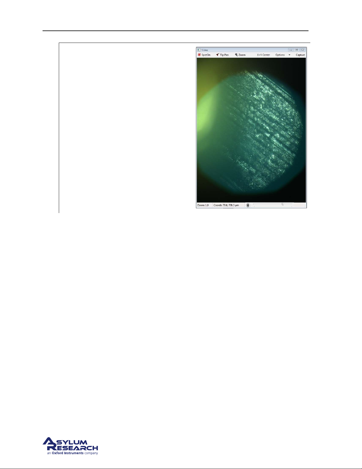
Going too far:
• If you cannot confirm you are focused
on the surface, slowly continue to lower
the objective until you see lots of coarse
looking features. These features are
typically scratches on the steel puck you
have mounted beneath the substrate. If
you see this type of structure, you have
5.
focused below the sample surface and
need to raise the objective.
• Slowly raise the objective until you
either see:
– 1st - a feature on the sample surface
or
– 2nd - the edge of the field
diaphragm or
– 3rd - the cantilever.
6. If you have raised the objective focus all the way up to the level of the cantilever then lower the
objective back down to focus on the field diaphragm and set the sample focus there. You will be
approximately 30µm higher than the actual sample. The result of this is a slightly longer time for
the system to engage the tip.
7. Once the tip and sample (Field Diaphragm) focus have been set, click on the ‘Move to Pre-Engage’
button and make any small adjustments to the AFM spot position or deflection voltage prior to
engaging the tip.
6.4. Imaging with the Droplet Holder
6.4.1. AC Mode Tuning Specifics
The technique of AC mode imaging in fluid relies on the motion of the piezoelectric actuator in the
droplet holder to be sent to the cantilever through the fluid. This indirect or ”acoustic” drive of the
cantilever is greatly affected by the volume of fluid, the stiffness of the cantilever, and the frequency of
the drive signal.
In most cases it is not possible to simply auto tune the cantilever at it’s resonance. Manually tuning the
drive signal is the preferred method. In order to know where to tune you typically find the amplitude
peak by first measuring the thermal resonance of the lever. Once the thermal resonance is found, you
can overlay the thermal spectrum on the tune plot. As you drive the piezo in the droplet holder will see
several peaks in the amplitude plot as the drive frequency is swept. The peak you choose is typically the
highest peak inside or near the thermal peak.
BETA
Page 65
Page 70
Ch. 6. Fluid Imaging in a Droplet Sec. 6.4. Imaging with the Droplet Holder
Once an amplitude peak is selected and the engage routine initiated it is not uncommon for the system
to false engage as the driving forces on the cantilever change. It is therefore common to re-tune the
system as the tip gets closer to the surface. A typical tuning session goes something like this:
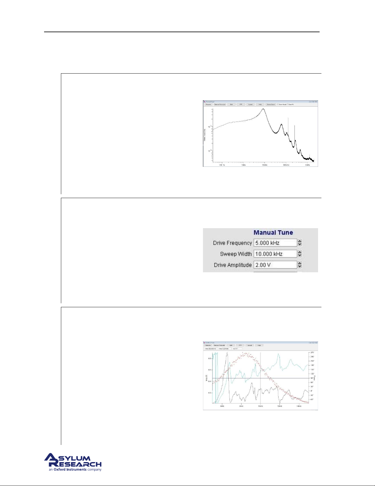
Capture a thermal plot
• Collect the thermal signature of the
cantilever.
• For more information on capturing
thermal spectra please read Applications
1.
Guide, Chapter: Thermals.
In this example the cantilever used is an
Olympus TR400PSA having a nominal air
resonance of about 40KHz and a spring
constant of .1nN/nM.
In water, the thermal resonance is about
7KHz.
Manually tune the cantilever
• In the manual tune parameters set the
drive frequency to the approximate
frequency of the cantilever’s thermal
2.
3.
resonance.
• Set the sweep width to 10KHz.
• Set the drive amplitude to 1-2v.
• Click on the continuous tune button and
sweep the drive frequency.
Select an amplitude peak
• Click on the append thermal check box
to overlay the thermal data onto the
amplitude plot
• Look for a peak inside the thermal
signature. Generally the peak with the
highest amplitude is the one to try. The
peak should have a smooth rise in
amplitude and have stable output as the
frequency is swept.
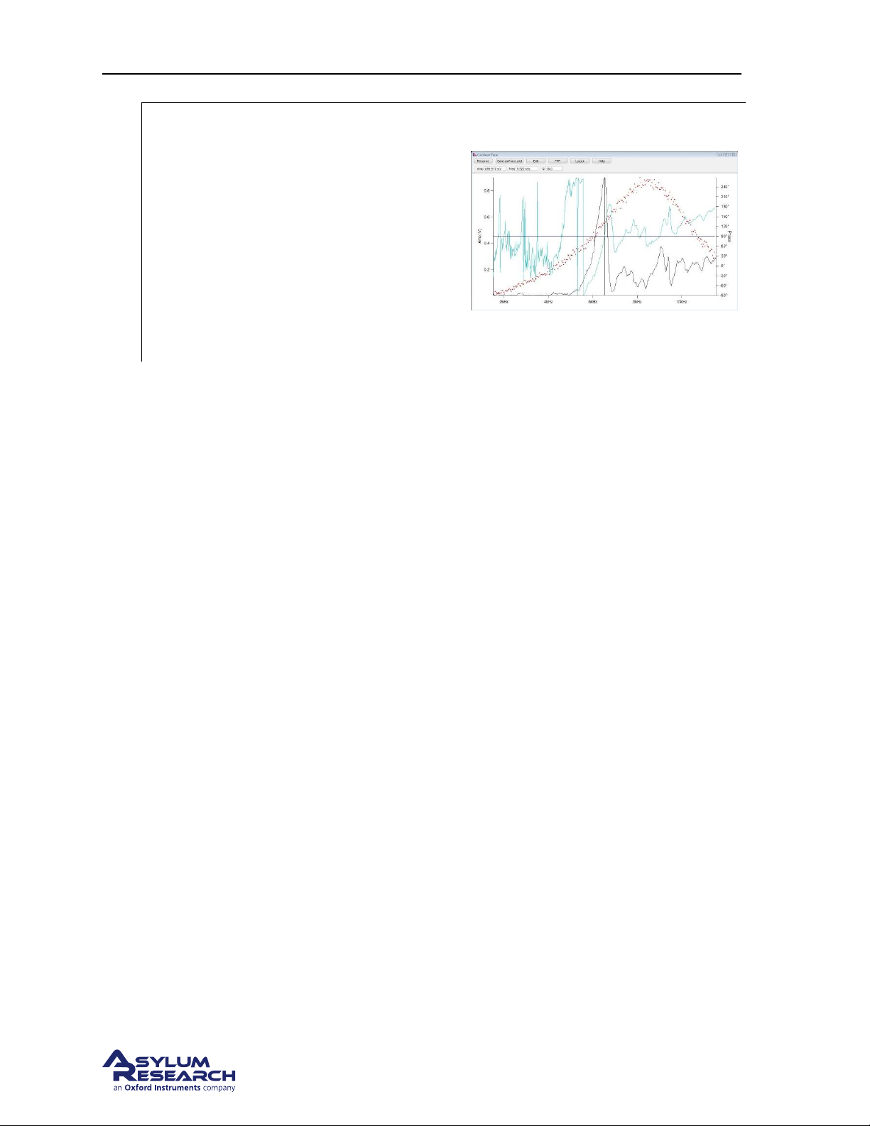
• The peak near 6Khz is good although
the lower amplitude peak at 9KHz
would also work.
BETA
Page 66
Page 71
Ch. 6. Fluid Imaging in a Droplet Sec. 6.4. Imaging with the Droplet Holder
Set the drive frequency and calibrate the
phase signal
• Move the mouse cursor to the apex of
the amplitude peak, right click and
4.
5. Click on the ’Stop’ button in the tune panel when the system is tuned.
6.4.2. Imaging Specifics
6.4.2.1. Engaging in fluid in AC mode
select ’Set Drive Frequency’
• The software will center the pot on the
peak.
• Click on the ’Center Phase’ button in
the tune panel to adjust the phase signal
to the center of it’s range.
As the tip is being lowered to the surface during the engage routine, the Cypher is doing a series of
triggered force curves looking for the free amplitude to equal the setpoint voltage. Once the free amplitude is seen as equal to the setpoint voltage, the system stops the approach and is considered to have
found the surface. This works pretty well but in fluid there are several things that can trigger a false
engagement.
• The Feedback Filter - The default frequency response of the feedback filter is 5KHz. Since the
resonance of the cantilever in this example is around 6.5KHz, the instrument is allowed to see
frequencies too close to the oscillating frequency of the lever. This will cause the software to
detect the alternating movement of the cantilever as the amplitude is changing and trigger a false
engagement. Lowering the feedback filter value to around 2KHz will avoid this. Using stiffer
cantilevers with a higher natural resonance will not need this adjustment.
• Hydrodynamic drag - The abrupt drop in the cantilever holder pillar during a motor step can
cause a jump in the deflection signal. This is caused by the drag of the liquid bending a low
spring constant cantilever. Lowering the Feedback Filter to around 2KHz will help reduce this
effect. Stiffer cantilevers will not show this problem.
• The amplitude changes due to the peak shifting frequency - As the probe is lowered to the surface,
the amount of liquid between the glass in the droplet holder and the sample surface can change
the coupling of the drive signal into the cantilever. This may excite the cantilever at a different
frequency so a previously tuned cantilever may not be in tune anymore. If the instrument triggers an engagement, you may want to go back to the tune panel and do a single tune to see the
amplitude response and re-tune if necessary.
Check for a real tip engage by clicking on the ’Engage’ button in the Sum and Deflection meter panel.
Reduce the setpoint voltage in the master controls panel and watch the behavior of the Z control voltage.
If by lowering the setpoint voltage you see the Z voltage move all the way to 150volts then the system
BETA
Page 67
Page 72
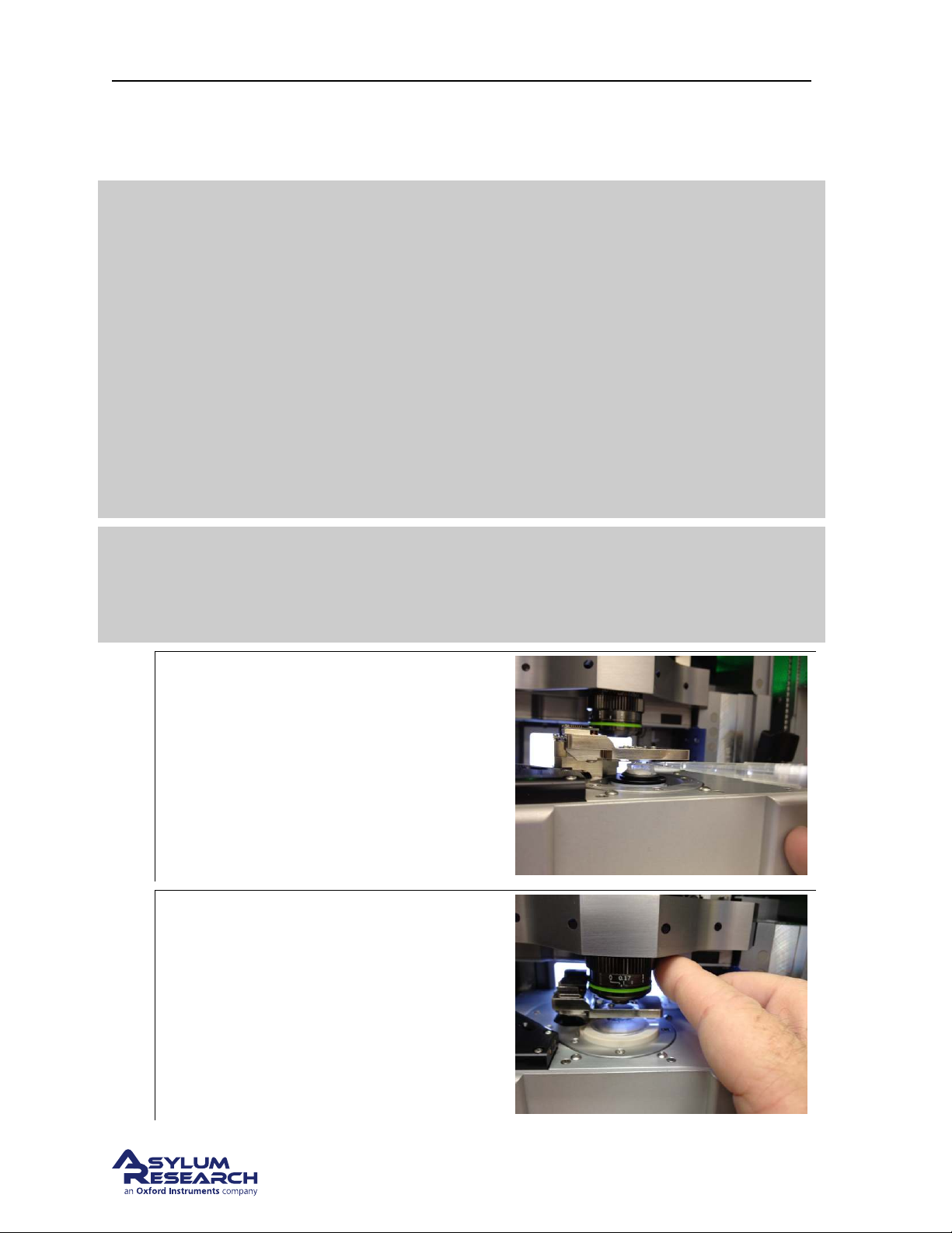
Ch. 6. Fluid Imaging in a Droplet Sec. 6.4. Imaging with the Droplet Holder
has false engaged and you should check the tuning of the lever and adjust as necessary. If you see the Z
control voltage move to a value and stop then you most likely have correctly engaged. Begin scanning.
One useful thing is to monitor the deflection signal. Normally the deflection signal
is not shown since the feedback signal is the Amplitude. Monitoring the deflection
signal is helpful because in some cases the deflection will jump up as though the
tip is has engaged in contact mode when the amplitude is falling. If this happens it
indicates that the amplitude signal may be the result of deflections from the
droplet holder components themselves resonating or the cantilever bending in a
Tip
way that produces angular motion of the optical spot and not the result of the
cantilever flexing at the tip end. If you see the deflection signal changing as
though it’s engaging in contact mode then most likely you should re-tune the
system and try driving the lever at a different frequency (choose a different peak).
This behavior is the result of using low spring constant cantilevers. Stiffer levers
typically do not do this.
To display the deflection signal, click on the ’Setup’ button in the Sum and
Deflection meter panel. Change the deflection from Auto to Show.
Do a force curve and monitor the amplitude signal. The amplitude signal should
Tip
show an abrupt drop to 0 volts just before tip contact is made. Doing a force curve
is equivalent to seeing the conditions of the last engage cycle during the tip
approach.
Adding additional fluid during scanning
During the experiment, you may find that the
tip develops a tendency to float off the
surface. This may be due to evaporation
1.
causing a loss of fluid volume which directly
affects the AC drive oscillating the cantilever.
If you suspect this has happening, use a
pipette to add additional fluid to the
tip/sample area and re-tune the system.
After scanning
2.
• After you are finished scanning move
the focus offset ring on the objective
back to 0mm.
BETA
Page 68
Page 73

Ch. 6. Fluid Imaging in a Droplet Sec. 6.5. Removal and Storage
6.5. Removal and Storage
6.5.1. Removing the Dish
Please see
1. Unscrew the sample dish from the scanner.
2. Thread the standard scanner magnetic insert into the scanner sample stage.
3. Use the point of a pair of tweezers to tighten the insert.
6.5.2. Storage
Always clean the cantilever holder before storage. If it is particularly dirty, disassemble it before cleaning. Please see
and the other parts and tools in its designated kit box.
Section 6.3.1 on page 57for details.
Section 7.2 on page 80 for the details. When clean and dry, store the cantilever holder
6.6. Cleaning and Repair
In daily use, the droplet holder can be cleaned by rinsing the exposed surfaces of the glass window
and cantilever clips with clean de-ionized water. Following the rinse, the holder can be dried using
low-pressure compressed air or by blotting with a soft tissue.
For thorough cleaning, the droplet holder must be disassembled. Only the parts exposed to the sample
liquid should be cleaned. The cantilever holder body and associated electronics should be kept dry.
The cantilever holder clip, window assembly and evaporation control components can be cleaned by
soaking in ethanol. Sonication of the parts can also be performed. Rinse the parts in clean de-ionized
water. Dry the parts with either low-pressure compressed air or a soft tissue before reassembling the
holder.
6.6.1. Disassembly
The following steps will guide you through removing various components for cleaning as well as reassembling the holder afterward.
Before you disassemble the droplet holder, take the time to familiarize yourself with the way it is assembled.
The key components are:
• The cantilever clip and the associated mounting hardware
• The droplet holder window assembly and associated mounting hardware
As you disassemble the holder, take note that the screws for attaching the window assembly are a
specific length. Reassembling the window with the longer screws can result in damage to the glass by
either cracking or causing it to become detached from the metal mounting ring.
BETA
Page 69
Page 74
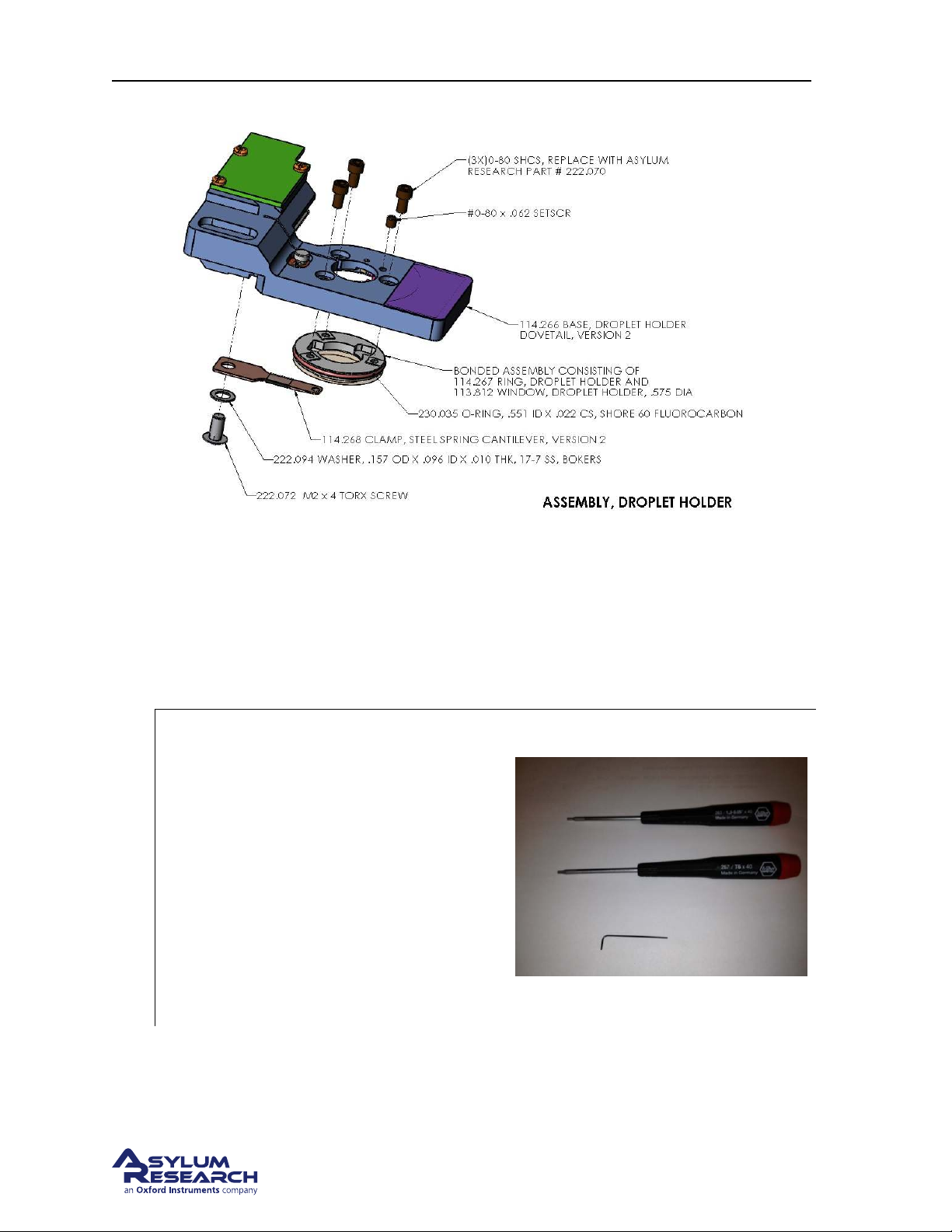
Ch. 6. Fluid Imaging in a Droplet Sec. 6.6. Cleaning and Repair
Figure 6.3.: Droplet Cantilever Holder Assembly Overview
• Use only 0-80 x 7/64” Socket Head Cap Screws to attach the window assembly.
• Use only 0-80 x 1/16” Cup Point Socket Set Screws for the piezo preload screw.
Due to wear and tear of use, the droplet holder accessory kit comes with replacement screws. Please
contact Asylum Research for additional hardware if proper replacements cannot be obtained locally.
Required tools and fasteners:
• 0.050” hex driver or Allen wrench for
the 0-80 x 7/64” socket head screws to
attach the window assembly.
• T5 x 40Torx driver for removing the
1.
cantilever clip
• 0.028” hex driver or Allen wrench for
the 0-80 x 1/16” Cup Point Socket Set
Screws for the piezo preload screw.
Warning Using other fasteners than those
specified will damage your equipment.
BETA
Page 70
Page 75
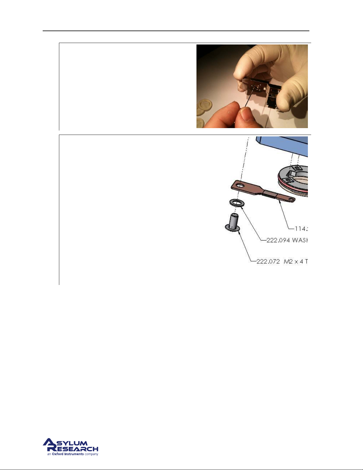
Ch. 6. Fluid Imaging in a Droplet Sec. 6.6. Cleaning and Repair
Loosen the piezo preload screw
Tools 0.028” hex driver or Allen wrench
2.
• Loosen the piezo preload setscrew ¼
turn.
Remove the spring clip
Tools T5 x 40 Torx driver
3.
• Remove the screw securing the spring
clip to the droplet holder body.
• Remove the clip from the droplet holder
body.
• Set the parts aside for cleaning.
BETA
Page 71
Page 76
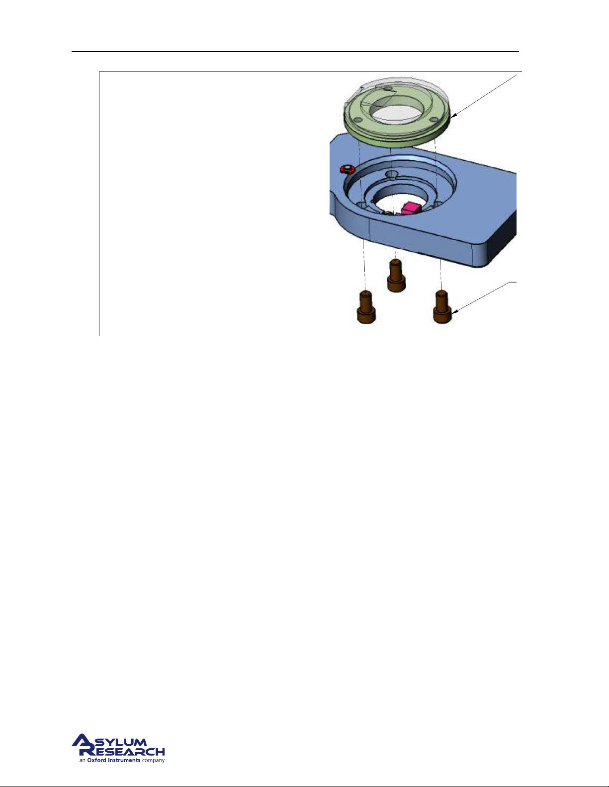
Ch. 6. Fluid Imaging in a Droplet Sec. 6.6. Cleaning and Repair
Remove the window assembly
Tools 0.050” hex driver or Allen wrench
• Remove the three screws holding the
glass insert into the holder body.
4.
• Remove the window assembly.
• Use a Q-Tip1to gently push the window
out of the Droplet holder body
Caution: Push gently on the top side of the
window. Be careful not to push on the piezo
actuator (Pink block in illustration)
6.6.2. Cleaning
The cantilever holder clip, window assembly and O-ring can be cleaned by soaking in ethanol. Sonication may result in weakening the glue bond of the adhesive used to attach the window to its mounting
plate so limited amounts of sonication (less than 15 minutes) of the parts is recommended. Rinse the
parts in clean de-ionized water. Dry the parts with either low-pressure compressed air or a soft tissue
before reassembling the holder.
The rest of the holder parts can be cleaned with a cotton swab and ethanol. Avoid areas with electrical
wiring or circuit boards. If you are unsure about having gotten the wrong bits wet, dry the parts (perhaps
under the warmth of a desk lamp) for a while. Dry the parts with low pressure compressed air in any
case.
6.6.3. Reassembly
1. Fit the o-ring into the groove in the window mounting plate. Spare o-rings are supplied in the
accessory kit for the droplet holder and more can be obtained from Asylum Research if necessary.
2. Place the window in the holder aligned so that the ramp in the glass points toward the hole for
mounting the cantilever spring clip. The O-ring around the edge of the window mounting ring
will prevent the window from fitting directly into the holder body.
3. Use a finger to gently push the window into the holder body. As you push on the window, be
aware that the o-ring will need to compress in the recess of the holder body. In order for this to
happen, it may be necessary to use a small tool like the point of a pair of tweezers to help guide
the O-ring to fit.
BETA
Page 72
Page 77
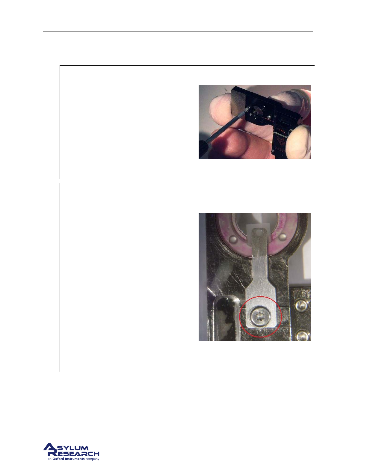
Ch. 6. Fluid Imaging in a Droplet Sec. 6.6. Cleaning and Repair
Note: There is a small recessed area in the metal ring where the piezo actuator fits. Be careful not to hit
the piezo or twist the window into position.
Secure the window assembly
Tools 0.050” hex driver or Allen wrench.
• Using a finger to hold the window in
place, thread the three 0-80x7/64”
1.
socket head screws the window to the
holder using. Once all three screws are
started, gently tighten them with
uniform pressure.
Note Do not over tighten the screws. A small
amount of torque is all that’s required.
Install the cantilever clip
Tools 0.050” hex driver or Allen wrench.
• Lay the cantilever holder body circuit
board side down.
• Place the clip on the holder body with
the taper on the clip facing away from
the window.
Note The end of the clip is tapered to provide
2.
clearance between the underside of the clip
and the sample surface. Be sure the flat side is
against the glass and the taper is away from
the glass.
• Secure the clip to the holder with the
Torx screw and washer. The clip may
want to rotate as you tighten the screw.
Use a pair of tweezers to hold the clip in
the center of the ramp while you tighten
the screw.
6.6.4. Adjusting Piezo Preload
When first disassembling the droplet holder for cleaning, the preload screw was loosened. Doing this
allows you to readjust the compression on the piezo element properly after it is reassembled. This is
recommended since the amount of compression is very small and the piezo position may change when
you remove and reinstall the glass window.
BETA
Page 73
Page 78
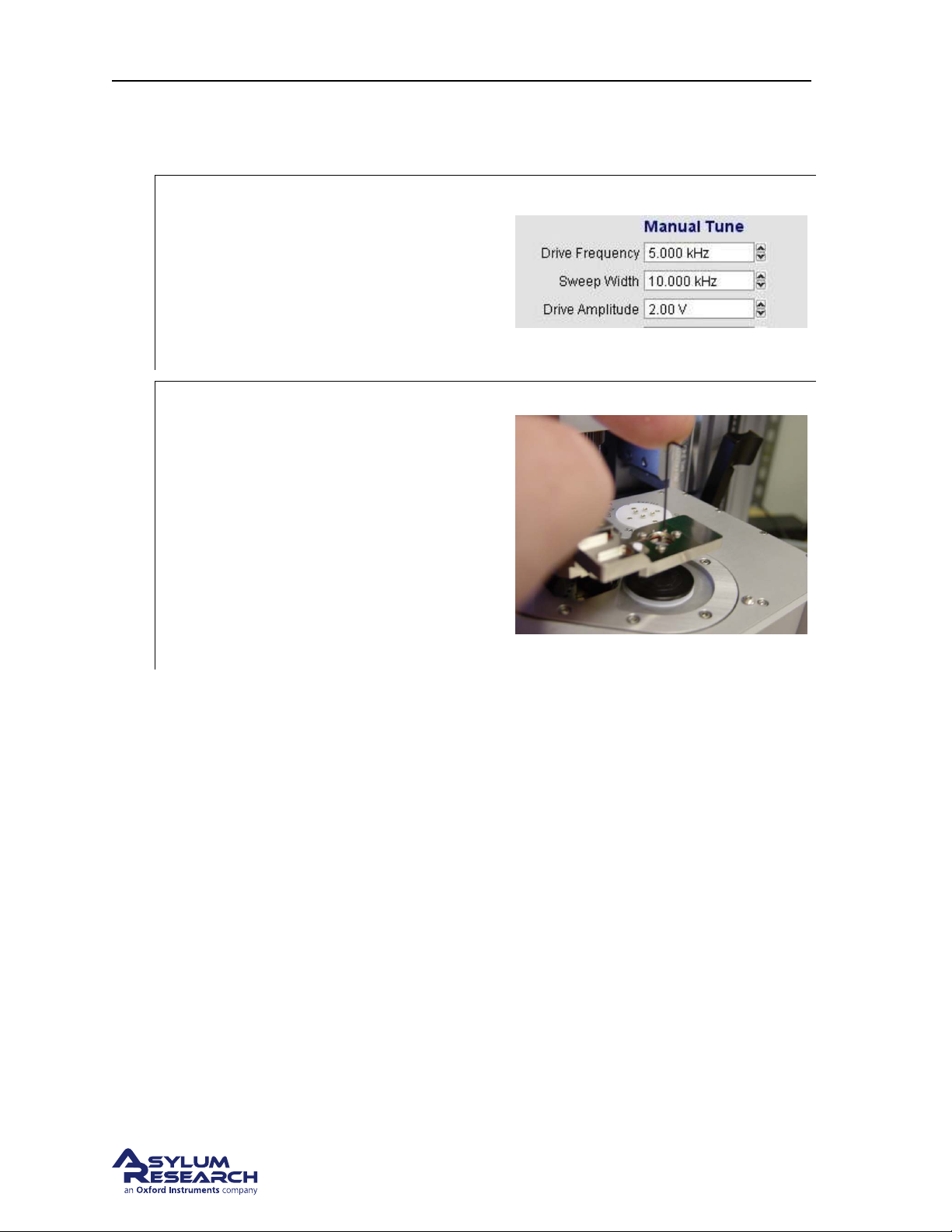
Ch. 6. Fluid Imaging in a Droplet Sec. 6.6. Cleaning and Repair
1. Install the Droplet holder into the scanner.
2. Lock the clamp on the scanner to secure the droplet holder.
Activate the tune sweep
• In the AR SPM Software, select the tune
3.
tab of the master panel.
• Under Manual Tune, set the parameters
as shown to the right.
• Hit the ‘Continuous’ (tune) button.
Adjust the piezo compression
Tools 0.028” hex driver or Allen wrench
• Listen for a small chirping sound
coming from the droplet holder.
4.
• Gently tighten the preload setscrew until
the chirping sound becomes abruptly
louder. This is the point where the set
screw has compressed the piezo into the
back of the window assembly. Once this
happens the preload is set.
6.6.4.1. Finishing up
1. Back to the software, under Manual Tune hit the Stop Tune button.
2. Done. Remove the cantilever holder and store it or put in a cantilever and start imaging.
BETA
Page 74
Page 79

Ch. 7. iDrive Imaging
7. iDrive Imaging
CH APTE R R EV. 1659, DATE D 1 0/07/2013, 22:54. US ER GUID E RE V. 1 714, DAT E D 10/25/2013, 20:36.
Chapter Contents
7.1 Nomenclature . . . . . . . . . . . . . . . . . . . . . . . . . . . . . . . . . . . . . . . . 76
7.1.1 Specific iDrive Droplet Holder Differences . . . . . . . . . . . . . . . . . . . . . 76
7.1.1.1 The cantilever clip assembly . . . . . . . . . . . . . . . . . . . . . 76
7.1.1.2 The window assembly . . . . . . . . . . . . . . . . . . . . . . . . . 77
7.1.1.3 Installing an iDrive cantilever . . . . . . . . . . . . . . . . . . . . . 77
7.1.2 Preparing for Imaging . . . . . . . . . . . . . . . . . . . . . . . . . . . . . . . 78
7.1.3 iDrive AC Mode Tuning Specifics . . . . . . . . . . . . . . . . . . . . . . . . . 79
7.1.4 Imaging Specifics . . . . . . . . . . . . . . . . . . . . . . . . . . . . . . . . . 80
7.2 Cleaning and Repair . . . . . . . . . . . . . . . . . . . . . . . . . . . . . . . . . . . . 80
7.2.1 Disassembly . . . . . . . . . . . . . . . . . . . . . . . . . . . . . . . . . . . . 81
7.2.2 Reassembly . . . . . . . . . . . . . . . . . . . . . . . . . . . . . . . . . . . . 81
7.3 Older Models . . . . . . . . . . . . . . . . . . . . . . . . . . . . . . . . . . . . . . . . 83
7.3.1 Cleaning and Repair . . . . . . . . . . . . . . . . . . . . . . . . . . . . . . . 83
7.3.1.1 Disassembly . . . . . . . . . . . . . . . . . . . . . . . . . . . . . 84
7.3.1.2 Cleaning . . . . . . . . . . . . . . . . . . . . . . . . . . . . . . . 86
7.3.1.3 Reassembly . . . . . . . . . . . . . . . . . . . . . . . . . . . . . . 87
7.3.1.4 Adjusting Piezo Preload . . . . . . . . . . . . . . . . . . . . . . . . 90
This section explains the use of the iDrive version of the Cypher Droplet Cantilever Holder. In addition
to the standard Droplet Cantilever Holder’s functionality, the iDrive version has the ability to drive a
small AC current through special iDrive compatible cantilevers. It also contains a small magnet, the field
from which causes a torque on the current flowing through an iDrive cantilever causing it mechanically
oscillate. This allows for an AC mode imaging experience in liquid superior to that achieved with
standard acoustically driven AC Mode imaging.
Before you start:
• We assume you understand the aspects of running this system safely: (
• You are familiar with the basic names of the hardware components and software controls (
ter 1 on page 3
• You have powered up the Cypher and launched the software: (
.)
Chapter 2 on page 10.)
• You are comfortable with AC Mode Imaging in Air, as instructed by the tutorial: (
Chapter 20 on page 229.)
Chap-
Chapter 4 on
page 17.)
BETA
Page 75
Page 80
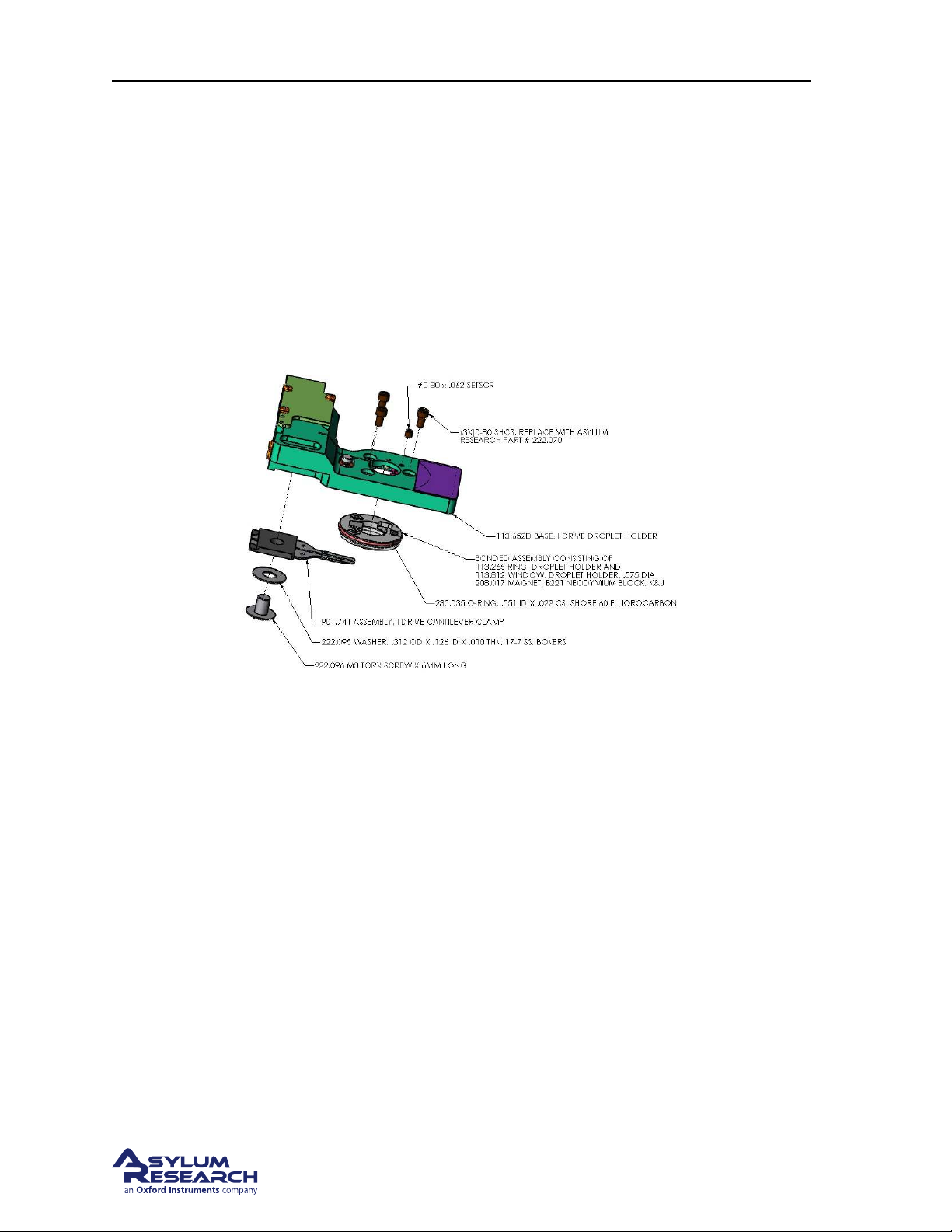
Ch. 7. iDrive Imaging Sec. 7.1. Nomenclature
• You have mastered fluid imaging in a droplet: (Chapter 6 on page 53.)
Review: The iDrive cantilever is based on the Droplet Holder covered in Chapter 7 on page 75. Please
read this chapter for general use of the cantilever holder and the basics of using it for contact mode and
AC imaging in liquid drops.
7.1. Nomenclature
See figure
7.1.1. Specific iDrive Droplet Holder Differences
Figure 7.1 on page 76
Figure 7.1.: iDrive Droplet Holder
7.1.1.1. The cantilever clip assembly
The spring clip that holds the cantilever in the droplet holder is an assembly of two thin clips molded
into a plastic block which together are the same basic shape as the single clip found on the standard
droplet holder. In addition to clamping the cantilever, the split clip design is used as pair of electrical
contacts to send the AC drive signal through an iDrive style cantilever. Inspecting the design of the
iDrive holder will show that there are two gold spring clips (Pogo pins) that contact the back of the
clips. These pins carry the AC drive signal from the droplet holder’s circuit board.
BETA
Page 76
Page 81
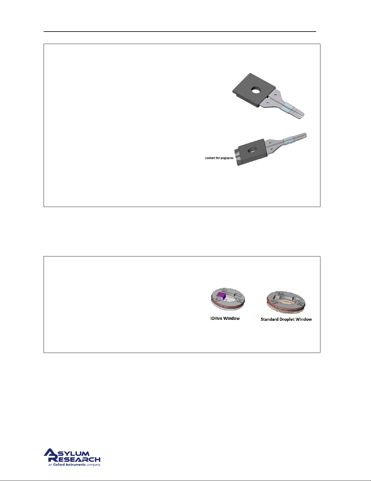
Ch. 7. iDrive Imaging Sec. 7.1. Nomenclature
Figure: Here are top and bottom views of the
split clip assembly.
Notice:
• the exposed area of the clips which are the
contacts for the pogo pins.
• the step along the molded section is used
for keying the clip into the droplet holder
body.
• the bands of Teflon act as a hydrophobic
barrier.
• like the standard droplet holder clip, the
bottom of the clips are tapered to provide
sample clearance.
7.1.1.2. The window assembly
The window assembly used in the iDrive droplet holder differs only in that there is a magnet bonded to
the top side of the glass window just above the cantilever.
Figure Here is a view of both window
assemblies for comparison.
Note Due to limited space in the design of the
droplet holders, the windows are not intended to
be interchangeable. However, the standard
window will fit into the body of the iDrive holder
but the window from the iDrive holder will not fit
in the standard droplet holder body.
7.1.1.3. Installing an iDrive cantilever
Installing an iDrive style cantilever is basically the same process as a standard cantilever. The difference
is that you need to pay close attention to the placement of the cantilever chip so that the split in the
contact area on the chip is between the split in the cantilever clip. This will create a circuit so that AC
current flows up through one clip, through the cantilever and returns through the other clip.
BETA
Page 77
Page 82
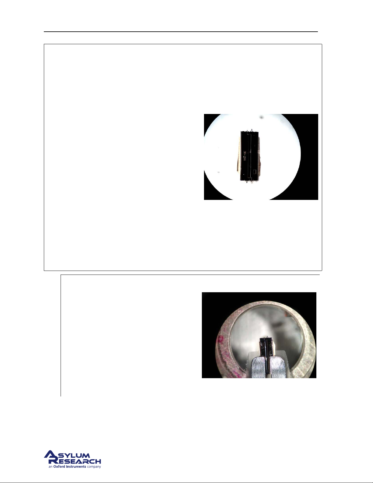
Ch. 7. iDrive Imaging Sec. 7.1. Nomenclature
Figure Here is a view of the surface of an iDrive
style cantilever.
Note
• The entire surface of the cantilever is
coated with a layer of gold.
• The insulating lines are etched in surface
to create to contact pads.
• Each of the outer pads are connected to
one leg of the smaller cantilever.
• The center area is isolated and is not
associated with the cantilever’s function.
• The typical resistance between the
electrodes is 10 Ohms with both of the
small cantilevers intact.
• It is okay to scan with both levers intact.
Breaking off the unused small lever will
simply raise the resistance of the
conducting path but generally doesn’t
improve performance.
Install an iDrive cantilever into the droplet
holder
• Align the chip under the electrodes so
that only one cantilever clip contacts
one of the contact pads.
1.
• Use an Ohm meter to check the
resistance between the cantilever holder
spring clips.
Note The center narrower electrode is
isolated so it’s okay to allow one of the clips
to touch it.
7.1.2. Preparing for Imaging
Since this cantilever holder is nearly identical mechanically to the Droplet Cantilever Holder, please
refer to
Chapter 7 on page 75 for details on
BETA
Page 78
Page 83
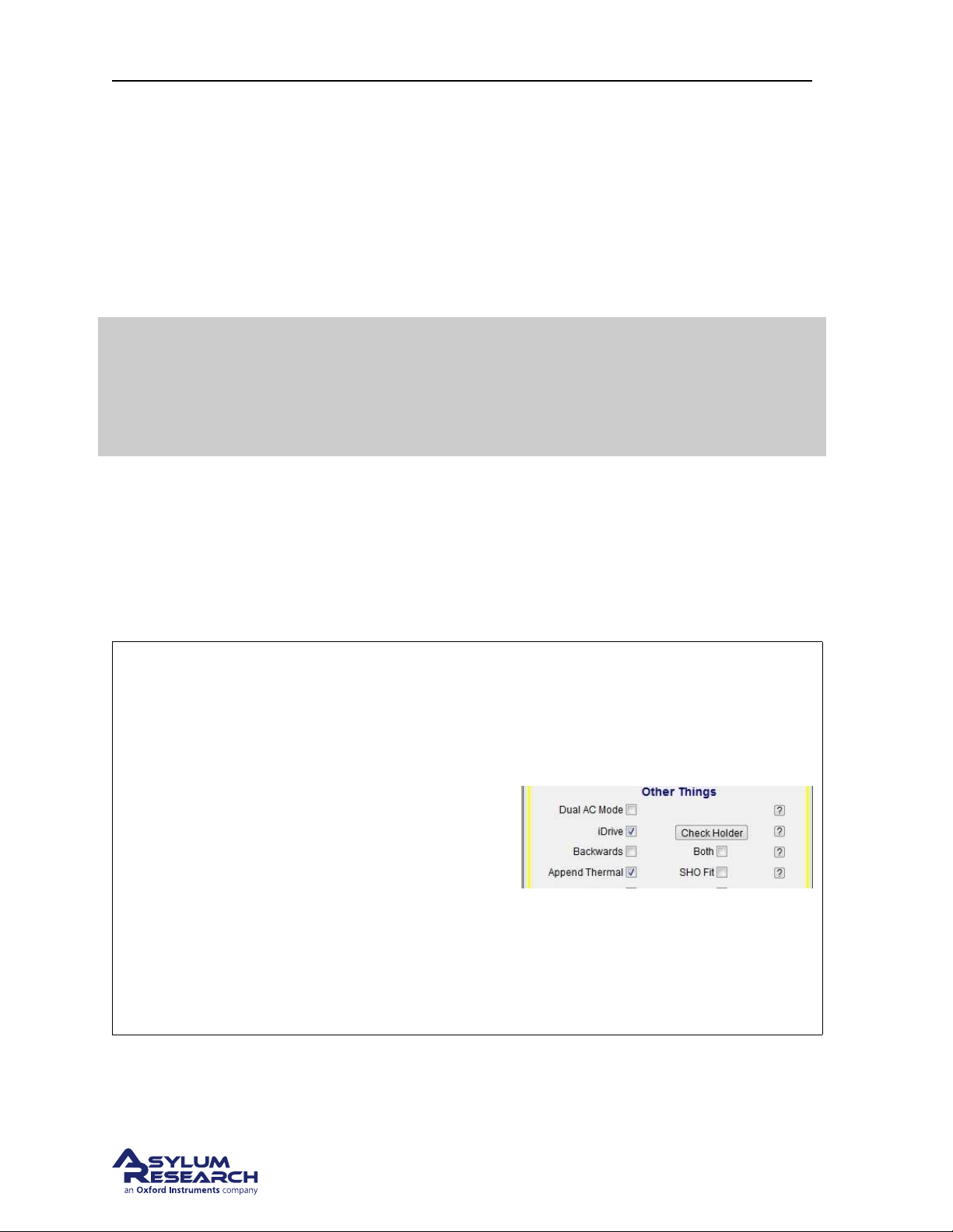
Ch. 7. iDrive Imaging Sec. 7.1. Nomenclature
• mounting the sample and the sample dish,
• using the evaporation shield,
• installing the cantilever holder in the scanner,
• contact mode or acoustic AC mode imaging specifics,
• removal and storage.
Only keep reading on here for the specifics of iDrive imaging and cleaning and assembly instructions.
For contact mode or acoustic AC mode imaging, there is no need need to use
special iDrive cantilevers. You can still use any standard cantilever for this type of
Tip
7.1.3. iDrive AC Mode Tuning Specifics
imaging, just as you would with the standard Droplet Holder. Only use special
iDrive cantilevers if you actually intend to use this method of exciting the
cantilever.
1. With an iDrive cantilever installed, align the laser onto to the lever and take a thermal measure-
ment.
2. Perform the same steps to manually tune the drive signal around the frequency range of the ther-
mal peak as you would do for acoustic AC mode imaging.
Feature: Activating the tune for iDrive
cantilevers
The software automatically scans the cantilever
holder socket and identifies the type of holder
you are using. In the Tune tab, the check box
labeled iDrive will automatically be checked if
an iDrive droplet holder is detected. If the iDrive
check box is checked, the drive frequency is
routed to the cantilever clip instead of the piezo
electric actuator.
• Uncheck the iDrive check box to deselect
the iDrive signal and send the drive
frequency back to the piezo for acoustic
AC imaging.
BETA
Page 79
Page 84
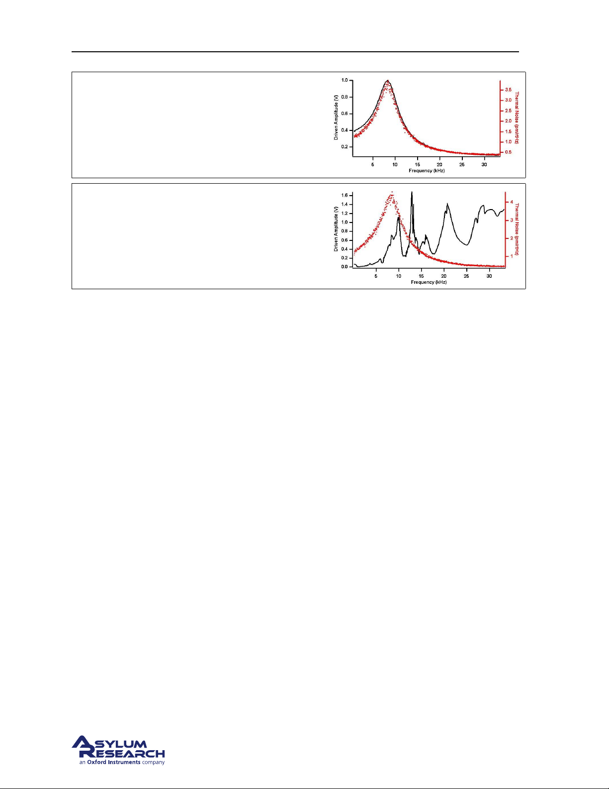
Ch. 7. iDrive Imaging Sec. 7.2. Cleaning and Repair
Figure iDrive Tune
Here is an example of a magnetically driven
iDrive cantilever
Figure Acoustic AC tune
Here is the same iDrive cantilever acoustically
tuned using the piezo actuator.
7.1.4. Imaging Specifics
Once the cantilever is tunes and you initiate the engage routine, you may notice the free amplitude
slowly decreases as the tip gets closer. This is due to the interacting of the steel sample puck interfering
with the magnetic field lines emitted by magnet in the iDrive holder. As you see this begin to happen
you may wish to increase the drive amplitude in the main controls tab. Generally a few “UP” clicks
while the tip is approaching is all that’s needed.
As a point of reference, a free amplitude of around 500mv may require 2-5v of drive. This is not a
problem but simply a point to note as you learn to operate the system with these types of probes.
Another thing to note is that the volume of liquid has lilt affect over the amplitude response. Since the
cantilever is driven magnetically and not by pressure waves transmitted through the fluid.
After an imaging session is completed, clean the cantilever holder before storage. If it is particularly
dirty, disassemble it before cleaning. Please see
cantilever holder and the other parts and tools in its designated kit box.
7.2 for the details. When clean and dry, store the
7.2. Cleaning and Repair
In daily use, the iDrive cantilever holder can be cleaned by rinsing the exposed surfaces of the glass
window and cantilever clips with clean de-ionized water. Following the rinse, the holder can be dried
using low-pressure compressed air or by blotting with a soft tissue.
For stringent cleaning, the iDrive cantilever holder must be disassembled. Only the parts exposed to the
sample liquid should be cleaned. The cantilever holder body and associated electronics should be kept
dry.
The cantilever holder clip, window assembly, Mounting hardware and evaporation control parts can
be cleaned by soaking in ethanol. Sonication of the parts can also be performed. Rinse the parts in
clean de-ionized water. Dry the parts with either low-pressure compressed air or a soft tissue before
reassembling the holder.
BETA
Page 80
Page 85
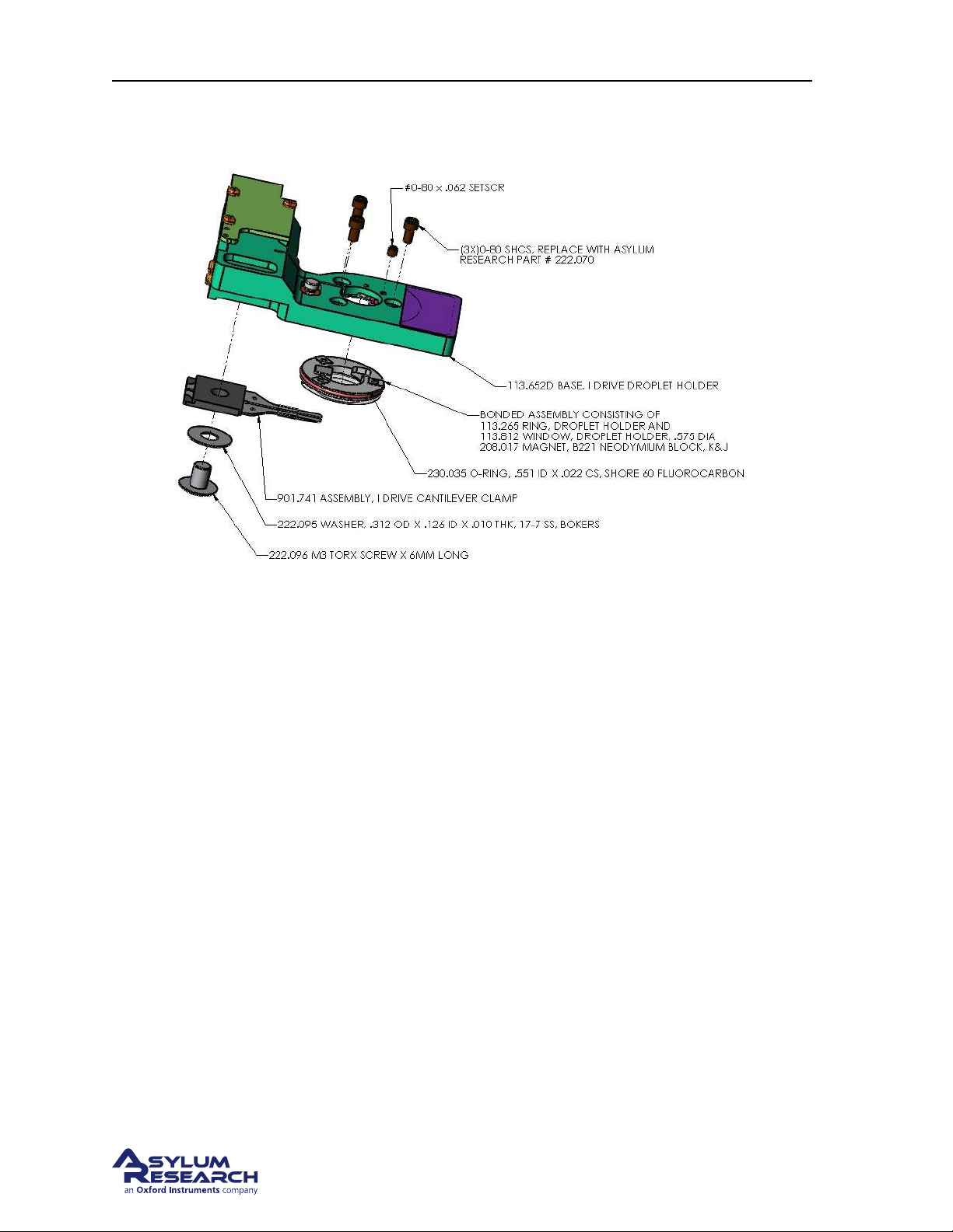
Ch. 7. iDrive Imaging Sec. 7.2. Cleaning and Repair
7.2.1. Disassembly
Figure 7.2.: Droplet Cantilever Holder Assembly exploded view
With the exception of the cantilever spring clip and the addition of a magnet to the window assembly,
the iDrive Droplet holder is mechanically identical to the standard Droplet Holder. Please refer to the
cleaning and repair section for the standard Droplet Holder.
To summarize the steps to disassembling and cleaning the holder:
1. Remove the cantilever clip.
2. Loosen the preload set screw above the piezo actuator.
3. Remove the three screws retaining the window.
4. Gently push the window out of the holder body.
5. Clean the parts.
7.2.2. Reassembly
To summarize the steps in reassembling the iDrive holder
1. Install the window assembly.
2. Install the cantilever clip assembly.
Section 6.6 on page 69
3. Set the preload on the piezo for acoustic AC imaging.
BETA
Page 81
Page 86
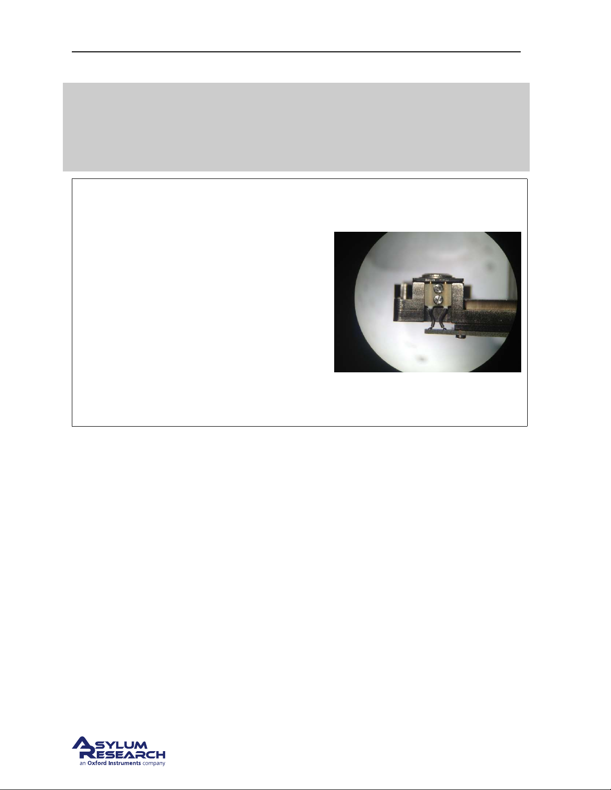
Ch. 7. iDrive Imaging Sec. 7.2. Cleaning and Repair
You may ask why the acoustic AC mode piezo is necessary when the iDrive
system is available as an AC drive for the cantilever. Practically speaking, it’s
Attention
Tip Pogo pins
The pogo pins are spring loaded and carry the
signal to the cantilever clip. Be careful not to
bend them as you reinstall the cantilever clip
assembly.
• Start by placing the cantilever clip in place
• Loosely thread the retaining screw. Don’t
forget the washer.
useful to switch back and forth between acoustically driving the cantilever and
using iDrive. Even if you don’t see the need, the next person using the cantilever
holder might, so it’s a good idea to perform the final piezo pre-load steps.
• Use tweezers to help keep the clip from
rotating until the step on the back of the
assembly mates with the step that is
machined into the holder body.
BETA
Page 82
Page 87
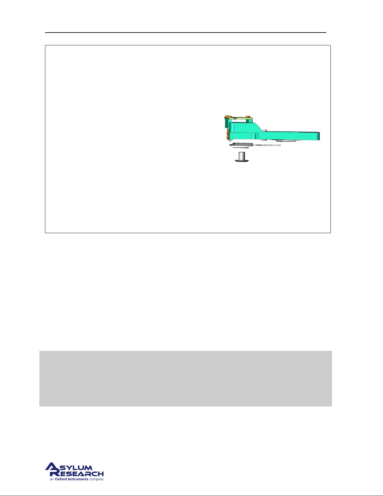
Ch. 7. iDrive Imaging Sec. 7.3. Older Models
Tip Aligning the cantilever clip on the body
The cantilever holder body and the clip assembly
have a step that engage to help align the clip
straight.
• The step in the plastic of the clip assembly
can be crushed if you tighten the retaining
screw with the clip improperly aligned.
• If the step becomes damaged residual
plastic may be pushed over the pogo pin
area and prevent the clip from touching the
pins.
• Take time to familiarize yourself with the
parts.
• Take your time when reassembling the
holder
7.3. Older Models
There has been one significant redesign to both the standard and iDrive droplet holder. The design
addressed:
• the complexity of disassembling and reassembling the holders after cleaning,
• Improvements in sealing the window from fluid leaks,
• ease of use of the evaporation shield.
If you have one of these versions of the droplet holders, please refer to this section for cleaning and
maintenance.
These revision holders are no longer made. There is an ongoing campaign to
replace all of these holders free of charge. If you have already received a
Note
7.3.1. Cleaning and Repair
replacement droplet holder and you you experience a failure of this design, we
cannot support it. If you have not yet received a replacement droplet holder, and
are experiencing a failure please contact Asylum Research.
In daily use, the iDrive cantilever holder can be cleaned by rinsing the exposed surfaces of the glass
window and cantilever clips with clean de-ionized water. Following the rinse, the holder can be dried
BETA
Page 83
Page 88
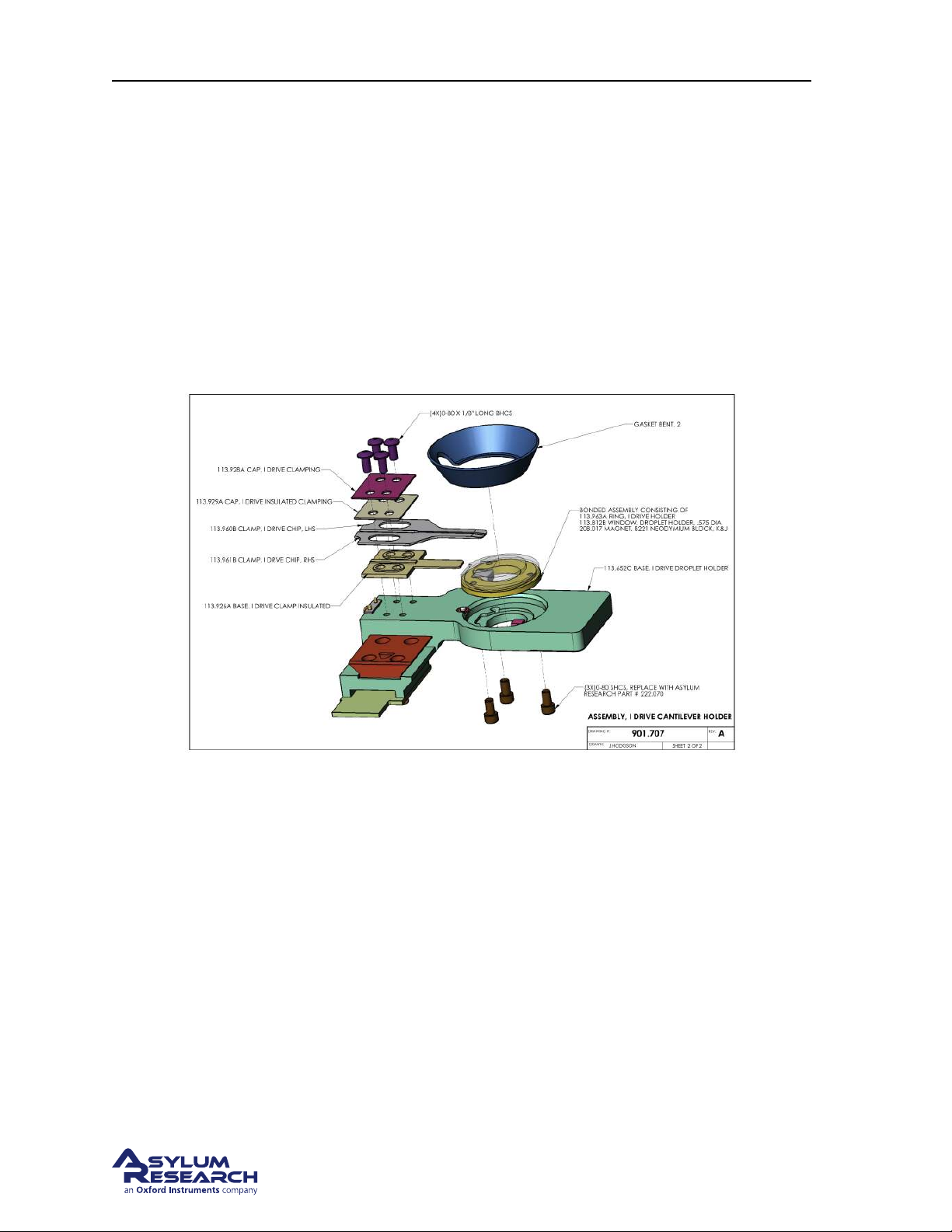
Ch. 7. iDrive Imaging Sec. 7.3. Older Models
using low-pressure compressed air or by blotting with a soft tissue.
For stringent cleaning, the iDrive cantilever holder must be disassembled. Only the parts exposed to the
sample liquid should be cleaned. The cantilever holder body and associated electronics should be kept
dry.
The cantilever holder clips, insulator plates, window assembly and evaporation skirt can be cleaned by
soaking in ethanol. Sonication of the parts can also be performed. Rinse the parts in clean de-ionized
water. Dry the parts with either low-pressure compressed air or a soft tissue before reassembling the
holder. please see
7.3.1.1. Disassembly
7.3.1.1
Figure 7.3.: Droplet Cantilever Holder Assembly Overview
The following steps will guide you through removing various components for cleaning as well as reassembling the holder afterward.
Before you disassemble the droplet holder, take the time to familiarize yourself with the way it is assembled.
The key components are:
• The cantilever clip and the associated mounting (insulating) plates
• The droplet holder window assembly
• The piezo actuator for performing AC mode.
As you disassemble the holder, take note that the screws for attaching the window assembly are shorter
than the screws holding the cantilever clips. Reassembling the window with the longer screws can result
in damage to the glass by either cracking or causing it to become detached from the metal mounting
ring.
BETA
Page 84
Page 89
Ch. 7. iDrive Imaging Sec. 7.3. Older Models
• Use only 0-80 x 7/64” Socket Head Cap Screws to attach the window assembly.
• Use only 0-80 x 1/8” Button Head Cap Screws to attach the cantilever holder clips.
• Use only 0-80 x 1/16” Cup Point Socket Set Screws for the piezo preload screw.
Due to wear and tear of use, the droplet holder accessory kit comes with replacement screws. Please
contact Asylum Research or your local Asylum distributor for additional hardware if proper replacements cannot be obtained locally.
Required tools and fasteners:
• 0.050” hex driver or Allen wrench for
the 0-80 x 7/64” socket head screws to
attach the window assembly.
• 0.035” hex driver or Allen wrench for
the 0-80 x 1/8” button head screws to
1.
attach the cantilever holder clip.
• 0.028” hex driver or Allen wrench for
the 0-80 x 1/16” Cup Point Socket Set
Screws for the piezo preload screw.
Warning Using other fasteners than those
specified will damage your equipment.
Loosen the piezo pre-load screw
Tools 0.028” hex driver or Allen wrench
2.
• Loosen the piezo preload setscrew ¼
turn.
Remove the spring clip
Tools 0.035” hex driver or Allen wrench
• Remove the screws securing the spring
3.
clips to the droplet holder body.
• Remove the clip and the spacer plates
from the droplet holder body.
• Set the parts aside for cleaning.
BETA
Page 85
Page 90
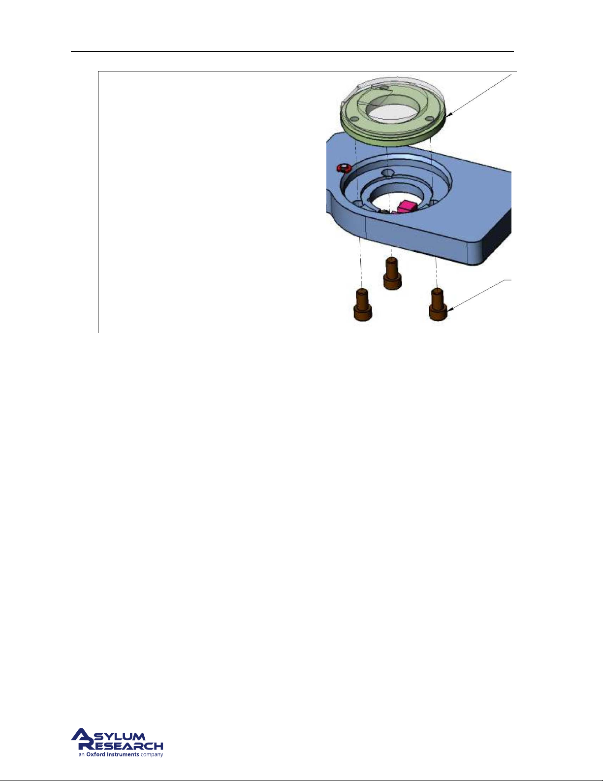
Ch. 7. iDrive Imaging Sec. 7.3. Older Models
Remove the window assembly
Tools 0.050” hex driver or Allen wrench
• Remove the three screws holding the
4.
glass insert into the holder body.
• Remove the window assembly.
• Separate the silicone evaporation skirt if
installed.
7.3.1.2. Cleaning
The cantilever holder clips, spacer plates, window assembly and evaporation skirt can be cleaned by
soaking in ethanol. Sonication of the parts can also be performed. Rinse the parts in clean de-ionized
water. Dry the parts with either low-pressure compressed air or a soft tissue before reassembling the
holder.
The rest of the holder parts can be cleaned with a cotton swab and ethanol. Avoid areas with electrical
wiring or circuit boards. If you are unsure about having gotten the wrong bits wet, dry the parts (perhaps
under the warmth of a desk lamp) for a while. Dry the parts with low pressure compressed air in any
case.
BETA
Page 86
Page 91
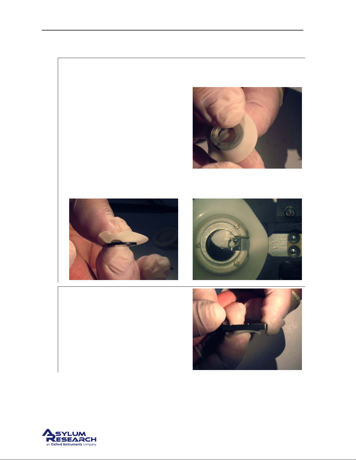
Ch. 7. iDrive Imaging Sec. 7.3. Older Models
7.3.1.3. Reassembly
Optional: Install the evaporation skirt
• Stretch the evaporation skirt around the
edge of the window. The edge of the
window has a small groove where the
skirt fits.
• Align the cutout in the skirt with the
cantilever pocket. The cutout is made to
allow a hole for the cantilever clip to fit
through the skirt.
Note The evaporation skirt is an optional part
and is not required for normal use. If you
decide not to use this part, please disregard
1.
the steps where reference to the skirt is
mentioned.
Position the window assembly
Tools 0.050” hex driver or Allen wrench.
2.
• Place the window in the holder and use
a finger to gently press the window into
position.
BETA
Page 87
Page 92
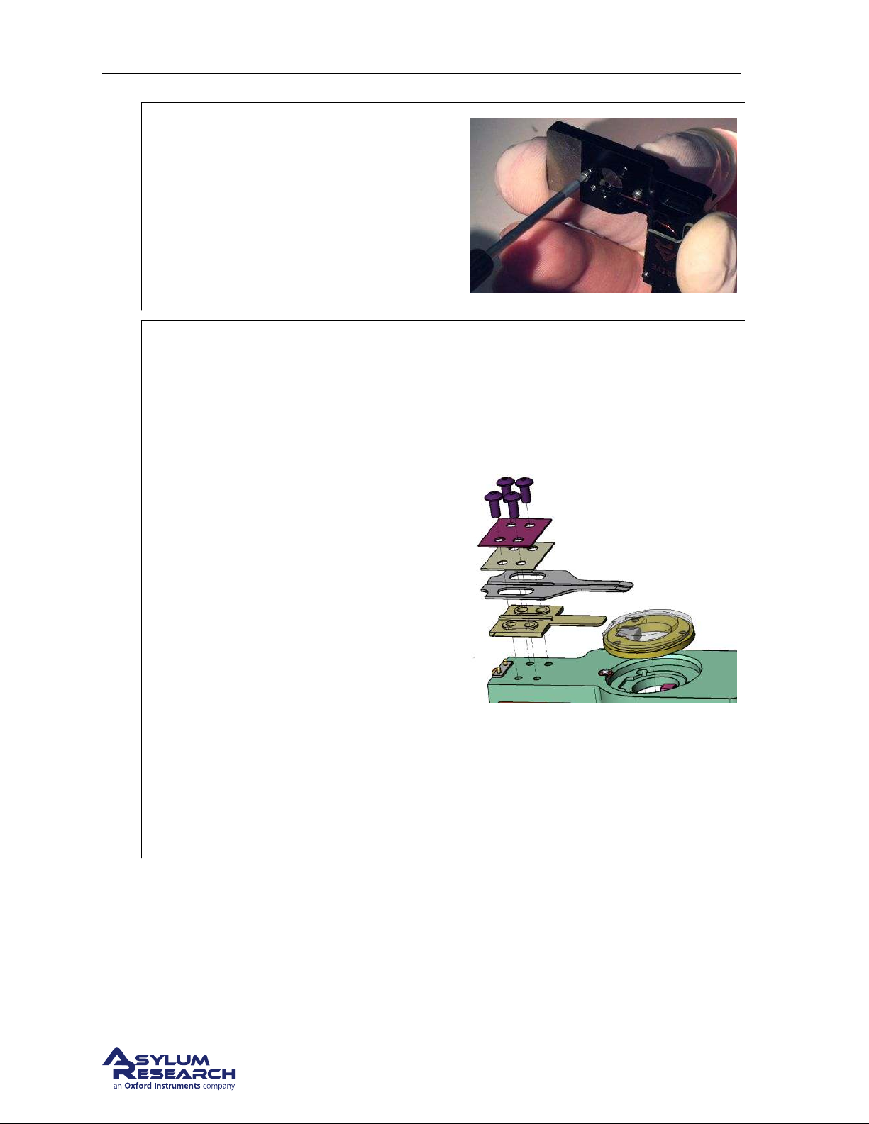
Ch. 7. iDrive Imaging Sec. 7.3. Older Models
Secure the window assembly
Tools 0.050” hex driver or Allen wrench.
• Secure the window to the holder using
3.
three 0-80 x 7/64” Socket Head Cap
Screws.
Note Do not over tighten the screws. A small
amount of torque is all that’s required.
Install the cantilever clip
Tools 0.035” hex driver or Allen wrench.
• Lay the cantilever holder body circuit
board side down.
• Using tweezers, place the bottom
spacer, clip, and top spacers. Pay
attention to the raised features on the
bottom spacer. They must face up to
mate with the clips.
• The top-most spacer is metal (purple in
4.
the drawing) the one below that is
plastic. Don’t reverse the order. The
clips must be sandwiched between
plastic or the iDrive current will be
shorted before it reaches the cantilever.
Note The tips of the clips are tapered. Be
sure the flat side is against the glass.
• If using the evaporation shield,
maneuver the clips through the hole in
the shield.
• Thread in the 0-80x1/8” button head
screws by only a few turns.
BETA
Page 88
Page 93
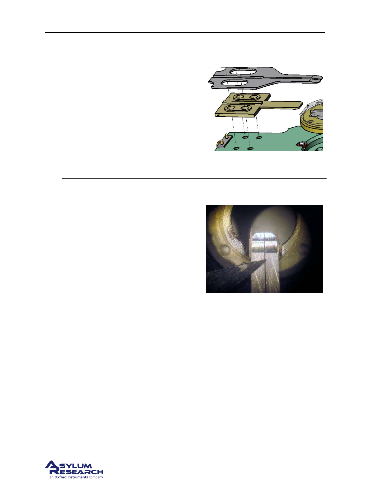
Ch. 7. iDrive Imaging Sec. 7.3. Older Models
Settle the parts together.
• Adjust the clips so that they seat over
the raised portions of the lower
insulator. As you shift the position of
the clips they will locate around the
5.
raised areas on the lower insulator.
When this happens the clips will feel
looser in the stack up of the assembly.
• Continue to gently tighten the screws
and readjusting the clip position until
the gap between the parts is gone. Do
not tighten the screws yet.
Adjust clips, tighten screws
Optional Tools Stereoscope, scalpel or razor
blade.
6.
• Inspect the two clips at the end where
the cantilever is held. The two clips
should not touch. Adjust the clips if
necessary. The point of a sharp razor or
scalpel works well for this step. A
stereoscope helps to see the details.
• Gently tighten the screws. Do not over
tighten the screws. A small amount of
torque is all that is required. Use only
your fingertips on the hex driver tool.
BETA
Page 89
Page 94
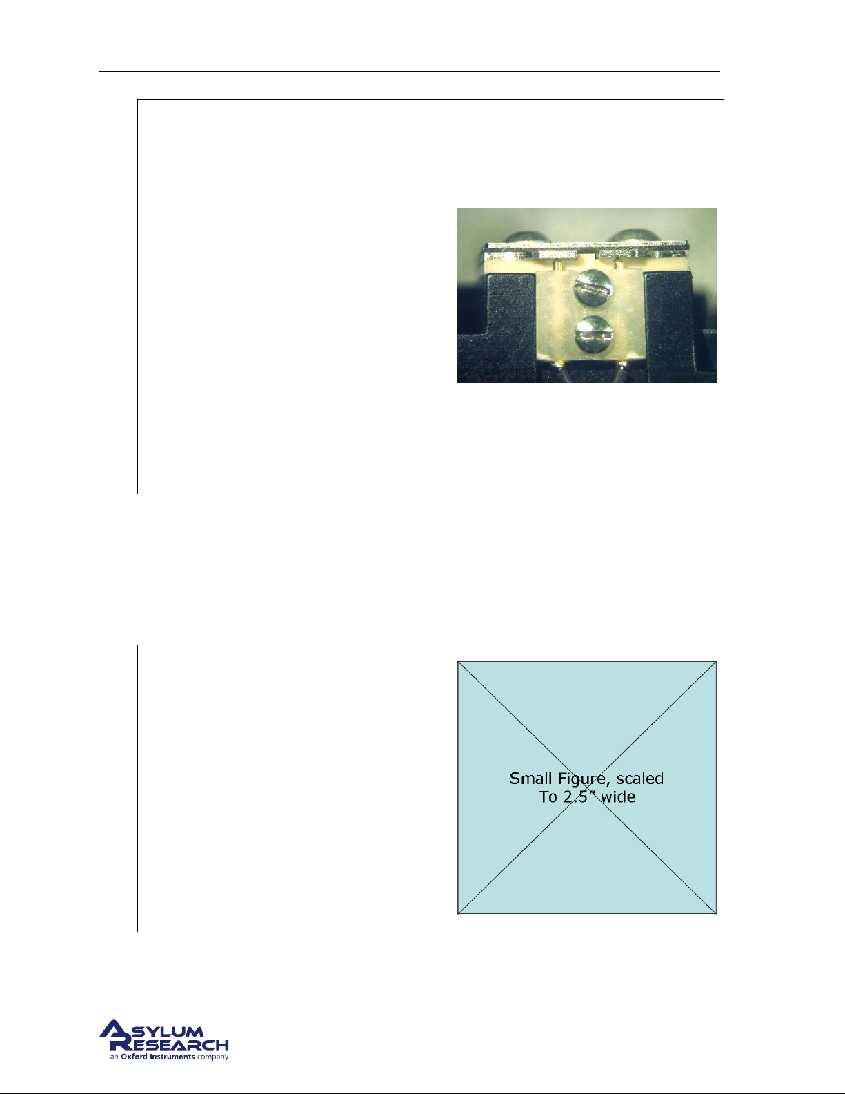
Ch. 7. iDrive Imaging Sec. 7.3. Older Models
Optional final inspection
Optional Tools Ohm meter.
• Where the clips are widest, measure the
resistance between the two clips. It
should be infinite (open circuit). If it is
finite, then the clips are touching and
you should loosen the four button head
screws and repeat the previous step.
7.
• The photo on the right shows a view
from behind where you should see a
stack-up (from top to bottom) of screw
heads, metal plate, plastic plate, clips,
thicker plastic plate, and then the
aluminum cantilever holder. Note the
two gold coated spring loaded pogo pins
that must make contact with the clips for
the iDrive system to function properly.
7.3.1.4. Adjusting Piezo Preload
When first disassembling the droplet holder for cleaning, the preload screw was loosened. Doing this
allows you to readjust the compression on the piezo element properly after it is reassembled. This is
recommended since the amount of compression is very small and the piezo position may change when
you remove and reinstall the glass window.
Install the cantilever holder
Tools 0.050” hex driver or Allen wrench
• Take the assembled cantilever holder,
without cantilever installed, to the
Cypher SPM.
1.
• Insert the cantilever holder into the
scanner.
• Finger tighten the screw which clamps it
down.
• No need to do any motoring up or down.
Move to the next step.
BETA
Page 90
Page 95
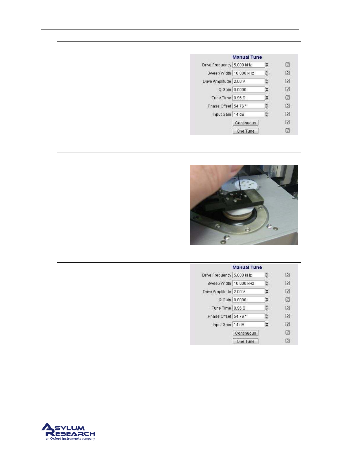
Ch. 7. iDrive Imaging Sec. 7.3. Older Models
Activate the tune sweep
• In the AR SPM Software, select the tune
tab of the master panel.
• Under Manual Tune, set the parameters
2.
as shown to the right. Note the phase
offset is not important and sweep time
of 1s is fine too.
• Uncheck the iDrive control, or the piezo
will not receive any drive signal.
• Hit the ‘Continuous’ (tune) button.
Adjust the piezo compression
Tools 0.028” hex driver or Allen wrench
• Listen for a small chirping sound
coming from the droplet holder.
3.
• Gently tighten the preload setscrew until
the chirping sound becomes abruptly
louder. This is the point where the set
screw has compressed the piezo into the
back of the window assembly. Once this
happens the preload is set.
Finishing up
• Back to the software, under Manual
Tune hit the ‘One Tune’ button to stop
4.
the chirping.
• Done. Remove the cantilever holder and
store it or put in a cantilever and start
imaging.
You may ask why the acoustic AC mode piezo is necessary when the iDrive system is available as
an AC drive for the cantilever. Practically speaking it’s quite useful to switch back and forth between
acoustically driving the cantilever and using iDrive. Even if you don’t see the need, the next person
using the cantilever holder might, so it’s a good idea to perform the final piezo pre-load steps above.
BETA
Page 91
Page 96

Ch. 8. Conductive AFM (ORCA)
8. Conductive AFM (ORCA)
CH APTE R R EV. 1659, DATE D 1 0/07/2013, 22:54. US ER GUID E RE V. 1 714, DAT E D 10/25/2013, 20:36.
Chapter Contents
8.1 Parts list . . . . . . . . . . . . . . . . . . . . . . . . . . . . . . . . . . . . . . . . . . 92
8.2 The ORCA Amplifier . . . . . . . . . . . . . . . . . . . . . . . . . . . . . . . . . . . . 94
8.2.1 Single Gain . . . . . . . . . . . . . . . . . . . . . . . . . . . . . . . . . . . . 94
8.2.2 Dual Gain . . . . . . . . . . . . . . . . . . . . . . . . . . . . . . . . . . . . . 95
8.3 Preparing for Imaging . . . . . . . . . . . . . . . . . . . . . . . . . . . . . . . . . . . . 96
8.3.1 Zeroing the ORCA Current and Sample Bias signals . . . . . . . . . . . . . . . 96
8.3.1.1 Zeroing the ORCA current signal . . . . . . . . . . . . . . . . . . . 96
8.3.1.2 Zeroing the Sample Bias . . . . . . . . . . . . . . . . . . . . . . . 97
8.3.2 Preparing the Sample . . . . . . . . . . . . . . . . . . . . . . . . . . . . . . . 98
8.3.2.1 Install the sample on the scanner and connect the bias lead . . . . . 98
8.3.3 Mounting the Cantilever . . . . . . . . . . . . . . . . . . . . . . . . . . . . . . 99
8.4 Imaging with the ORCA . . . . . . . . . . . . . . . . . . . . . . . . . . . . . . . . . . . 99
8.5 Testing the ORCA Amplifier . . . . . . . . . . . . . . . . . . . . . . . . . . . . . . . . . 99
8.5.0.1 Testing the first gain stage of a Dual Gain ORCA Amplifier . . . . . . 101
This chapter explains the use of the ORCA cantilever holder. In practical terms, the ORCA cantilever
holder is simply a standard air cantilever holder with the addition of a current to voltage converting
amplifier.
Basic AC and Contact mode imaging can be performed with the ORCA holder. One major difference
in its construction however is the use of the electrical connection to the cantilever spring clip. The
cantilever clip is used as a connection to the input of the current amplifier rather than a connection to
a bias voltage source. Because of this difference, the ORCA holder will not work for measurement
techniques where the tip needs to be biased.
EFM (Electric Force Microscopy), Surface Potential - SKPM (Kelvin Probe
Note
Microscopy), PFM( Piezoelectric Force Microscopy) imaging techniques require
the use of the standard air cantilever holder.
8.1. Parts list
The following items are included in the ORCA cantilever holder kit. These accessories are included in
both the single and dual gain versions of the holder.
DRAFT
Page 92
Page 97
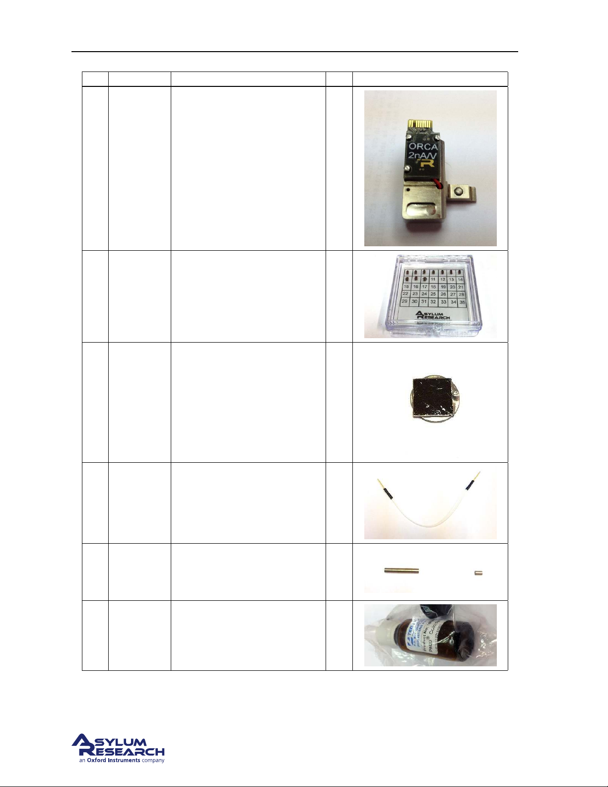
Ch. 8. Conductive AFM (ORCA) Sec. 8.1. Parts list
Itm Part # Item Description Qty Picture
901.730
1
901.708
ASTELEC-
2
3 823.009
01
ORCA Holder 2nA/V
Dual Gain ORCA 1uA/1nA/V
For other available versions see
8.2.
10 pack of conductive levers.
Used for the measurements
described in this section.
HOPG sample. Used as a
conductive AFM test sample.
See Section 8.3.2 on page 98.
1
1
1
4 448.079
5 208.05
6 290.160
Sample bias wire assembly.
Connects sample to voltage
source on top of the scanner. See
Step 1 on page 98.
Samarium Cobalt Magnet, 0.07”
D X 0.104” L. Used to connect
the bias wire to the sample. See
Section 8.3.2 on page 98.
Leitsilber Conductive Paint, 0.5
Oz. Used to conductively glue
the sample to an AFM disc. See
Section 8.3.2 on page 98.
DRAFT
6
6
1
Page 93
Page 98
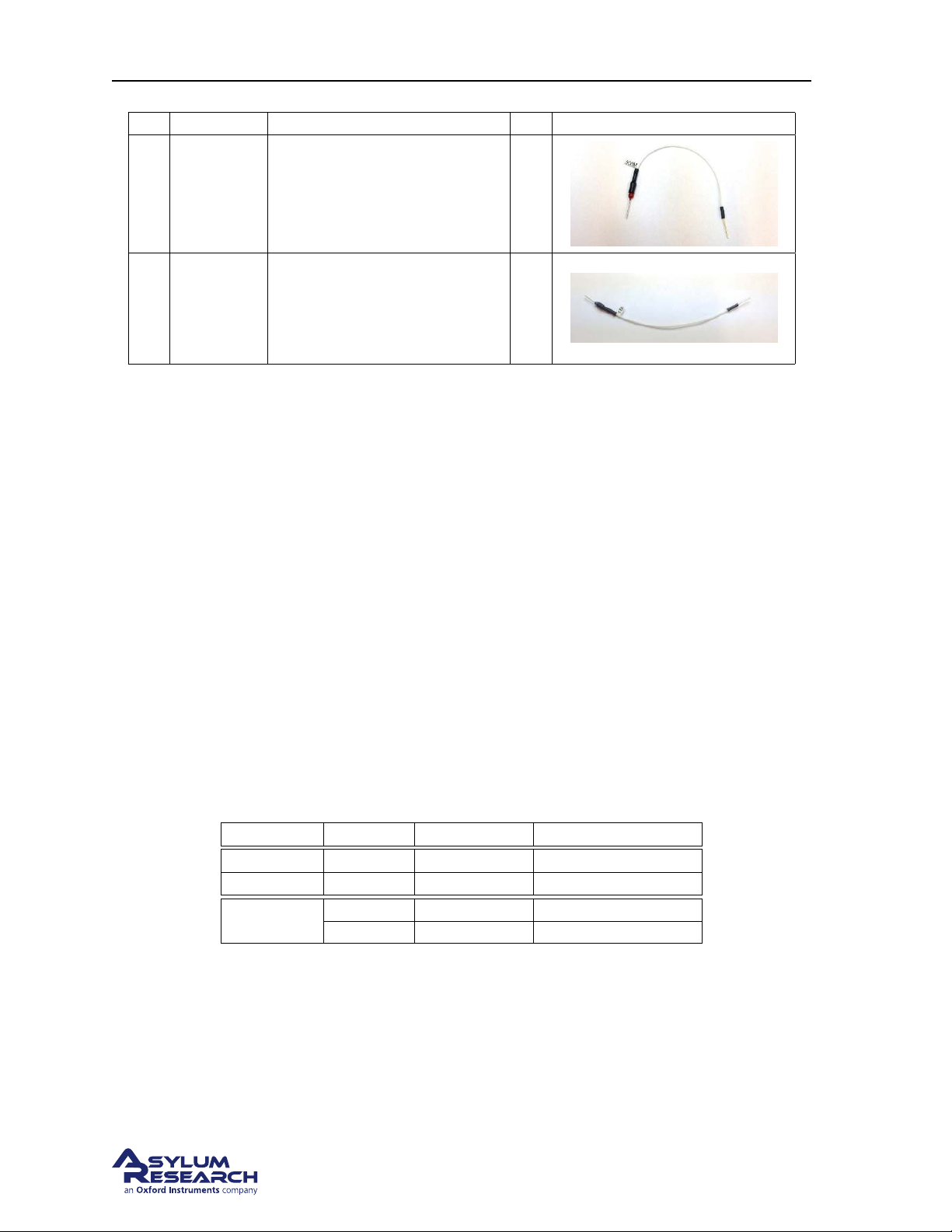
Ch. 8. Conductive AFM (ORCA) Sec. 8.2. The ORCA Amplifier
Itm Part # Item Description Qty Picture
Cypher ORCA 500M Resistor
7 448.082
8 448.081
Assembly. A 500M Ohm Test
Resistor. See Section 8.5 on
page 99.
Cypher ORCA 1M Resistor
Assembly. A 1M Ohm Test
Resistor (Dual Gain ORCA
Only). See
page 99.
Section 8.5 on
1
1
8.2. The ORCA Amplifier
There are a variety of ORCA cantilever holders each based on either a single or dual amplification
design. The design type and amplification gain are labeled on the top of the holder. Like all the Cypher
cantilever holders, a built-in circuit in the holder allows the software to automatically sense the type of
holder and configure the system accordingly.
The amplification range of the ORCA amplifier is expressed by it’s sensitivity. Basically the ability to
produce a voltage output from a certain current flow into the tip. In terms of the full range of the ORCA
amplifier, the output is +/-10v so multiplying the sensitivity by +/-10 will tell you the full range.
The ORCA amplifier incorporates the use of a trans-impedance amplifier which converts the input current from the tip to an output voltage. The input potential of the amp is referenced to ground so the tip
is essentially held at 0v potential. During the measurement, the sample can be biased between +/-10v
using a voltage source provided by the Cypher electronics.
Each ORCA cantilever holder has a fixed gain(s) to provide the highest current measurement range while
considering the lowest noise. The following ORCA holders are currently available. Custom holders can
be configured on request.
Part number Sensitivity Current Range Typical noise 1-1KHz
901.730 2nA/V +/-20nA 1.5pA
901.737 0.2nA/V +/-2nA 750fA
901.708
8.2.1. Single Gain
1nA/V +/-10nA 3pA
1uA/V +/-10uA 75pA
Here is a conceptual block diagram of the single gain ORCA amplifier. The sample is biased from a
voltage source within the Cypher electronics. The feedback resistor R1 sets the amplifier’s sensitivity. The output signal representing tip/sample current flow can be monitored by enabling the ’Current’
channel in the master channel control panel. See
Figure 8.1 on page 95.
DRAFT
Page 94
Page 99
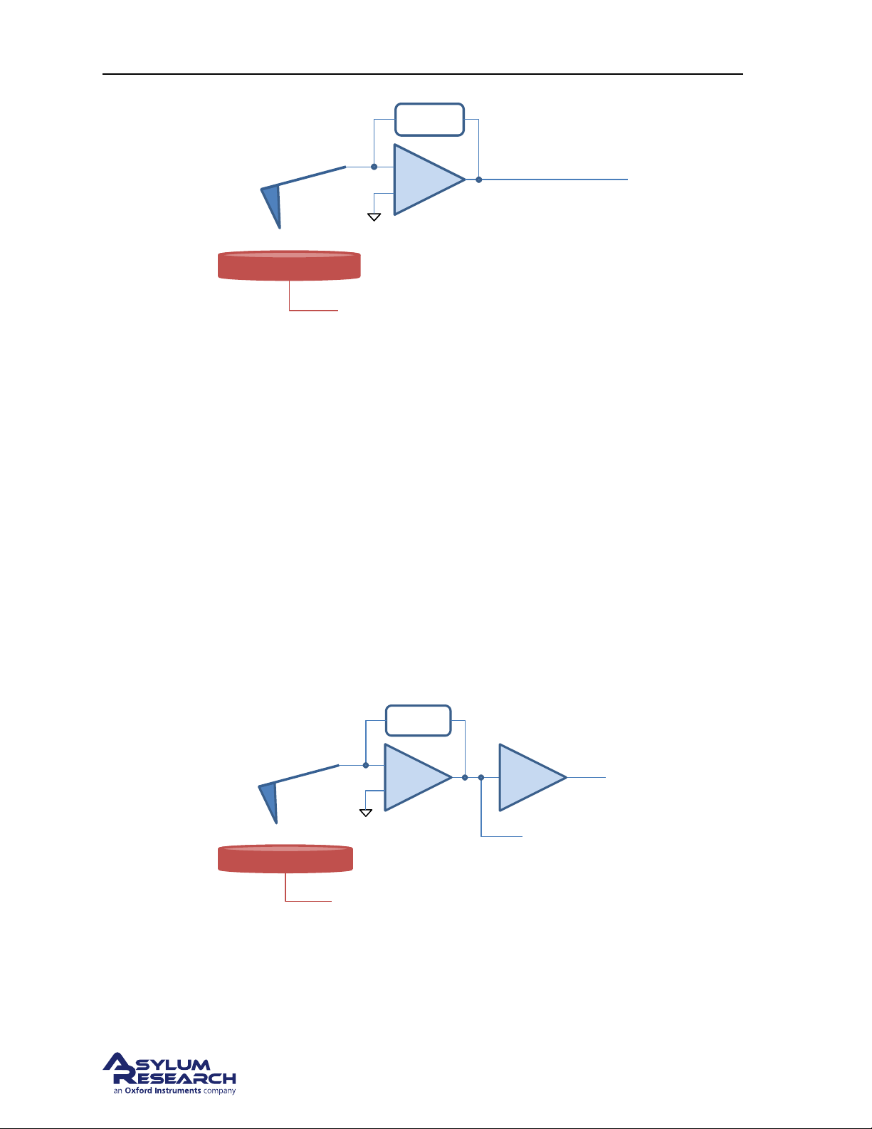
Ch. 8. Conductive AFM (ORCA) Sec. 8.2. The ORCA Amplifier
Sample Bias
Feedback
Resistor
Sample
I to V
Current
Sample Bias
Feedback
Resistor
Sample
I to V
Current
Current2
G=1000
Feedback
Resistor
Figure 8.1.: Single Gain ORCA
8.2.2. Dual Gain
A conceptual diagram of the dual gain ORCA amplifier shows the initial current to voltage converter
stage feeding the input of a second gain stage to create an additional output signal. In the case of this
design the more sensitive signal comes from the second stage and is monitored as ’Current’ from the
master channel panel like the single gain ORCA holder.
The output of the current to voltage amplifier’s first stage has a lower gain (more total current range)
signal is monitored as ’Current 2’ from the master channel panel.
Having a dual gain design is useful in that it expands the dynamic range of your measurement capability
but at a sacrifice of some increased noise at small current levels. In many cases the sample you may
wish to measure may have widely different regions of conductivity where the current may be too large
for the range of the more sensitive stage but suitable for the lower gain stage where more current can
me measured. In this case it is common to see the ’Current’ signal (high gain stage) saturate while the
’Current 2’ signal show a measurable current flow. See
Figure 8.2.: Dual Gain ORCA
Figure 8.2 on page 95.
DRAFT
Page 95
Page 100
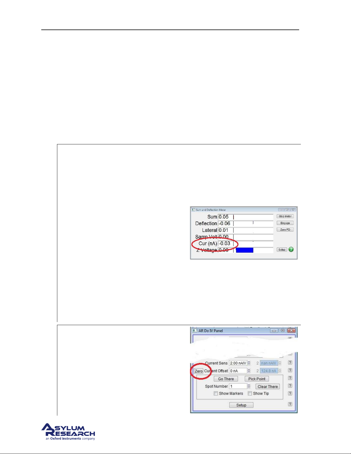
Ch. 8. Conductive AFM (ORCA) Sec. 8.3. Preparing for Imaging
8.3. Preparing for Imaging
8.3.1. Zeroing the ORCA Current and Sample Bias signals
The signal path through the Cypher can pass through many stages of signal conditioning. Each particular
circuit in the signal path can introduce a voltage offset which when added together can skew the zero
point of your measurement. The following adjustments should be made to your system prior to imaging.
8.3.1.1. Zeroing the ORCA current signal
1. Start the Cypher software if not already running.
2. Select contact mode as an imaging mode.
Install the ORCA holder into the scanner’s
tip engage pillar.
• The software will automatically add the
ORCA current and Sample Voltage to
the items shown in the SUM and
Deflection meter window.
• Push the scanner into the chassis and
close the enclosure door. The ORCA
current amplifier is sensitive to RF and
3.
other emitted signals such as florescent
lighting.
• Note the current being registered in the
Cur display. In this example, the offset
current is around -30pA.
Note If the Sum and Deflection meter
window does not update, Try adding Current
as one of the data channels in the Master
Channel panel and then reselect Contact
mode as the imaging mode the system.
Open the Do IV control panel
• Go AFM Controls to locate the DoIV
panel.
• Locate the Current Offset parameter at
4.
the bottom of the window.
Note If you are using a Dual Gain ORCA
holder holder, the Current 2 offset and Sens.
will be active.
DRAFT
Page 96
 Loading...