

Asus ZE550KL Repair Guide

ZE500KL
Hardware Introduction
2015.3.24

System
System
Introduction
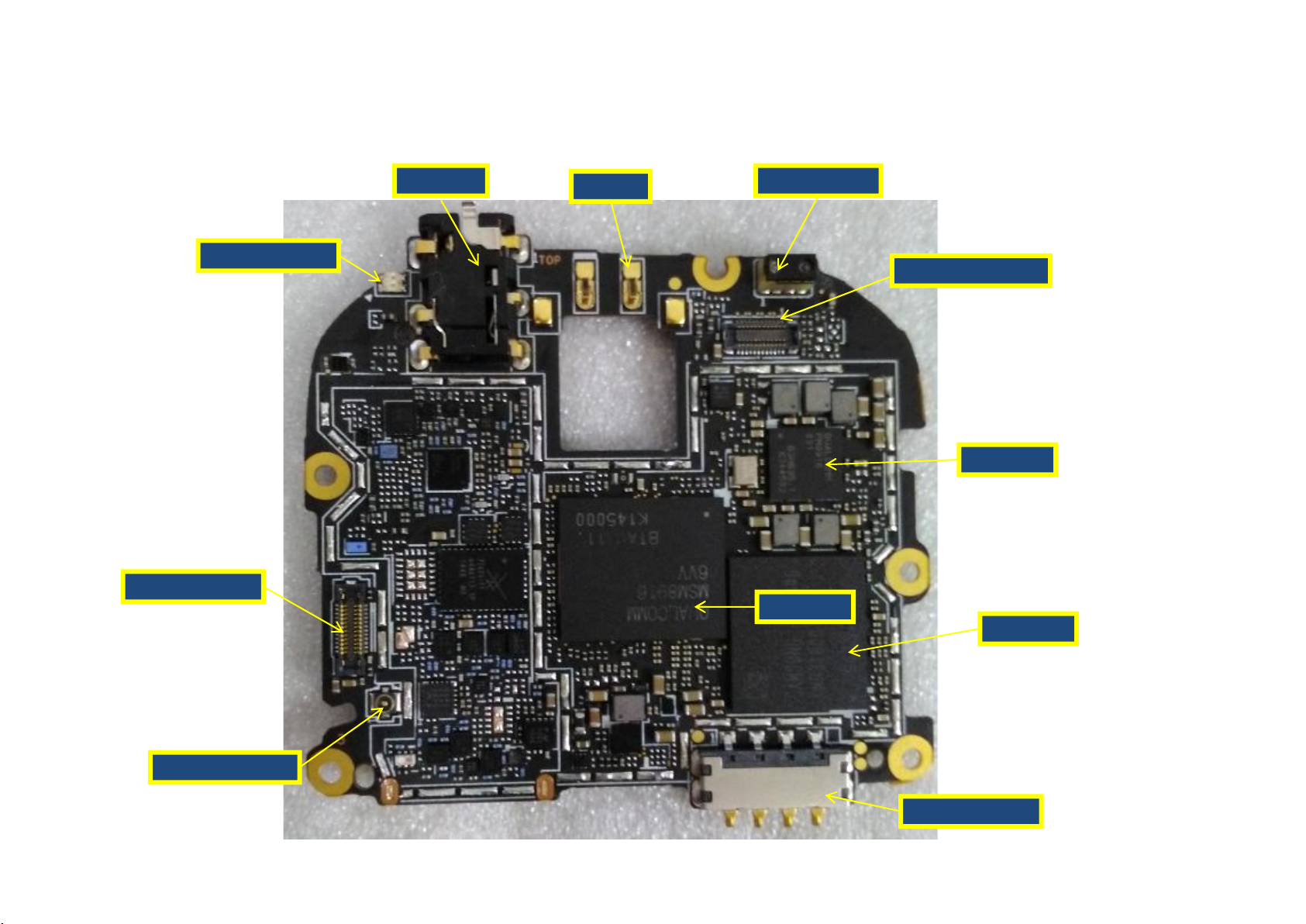
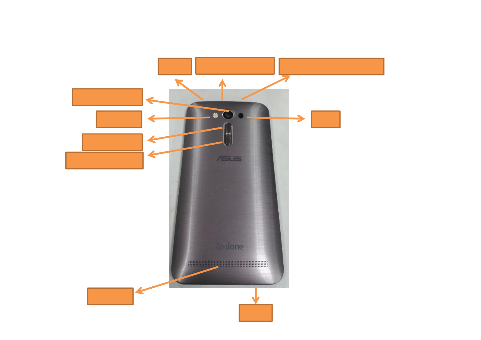
Assembly Chart TOP VIEW
Audio Jack
PWR Key
5M Front Camera
ALS & P-Sensor
R&G Indicator
Antenna connector
Battery Connector
IO Connector
SOC
MCP
PMIC
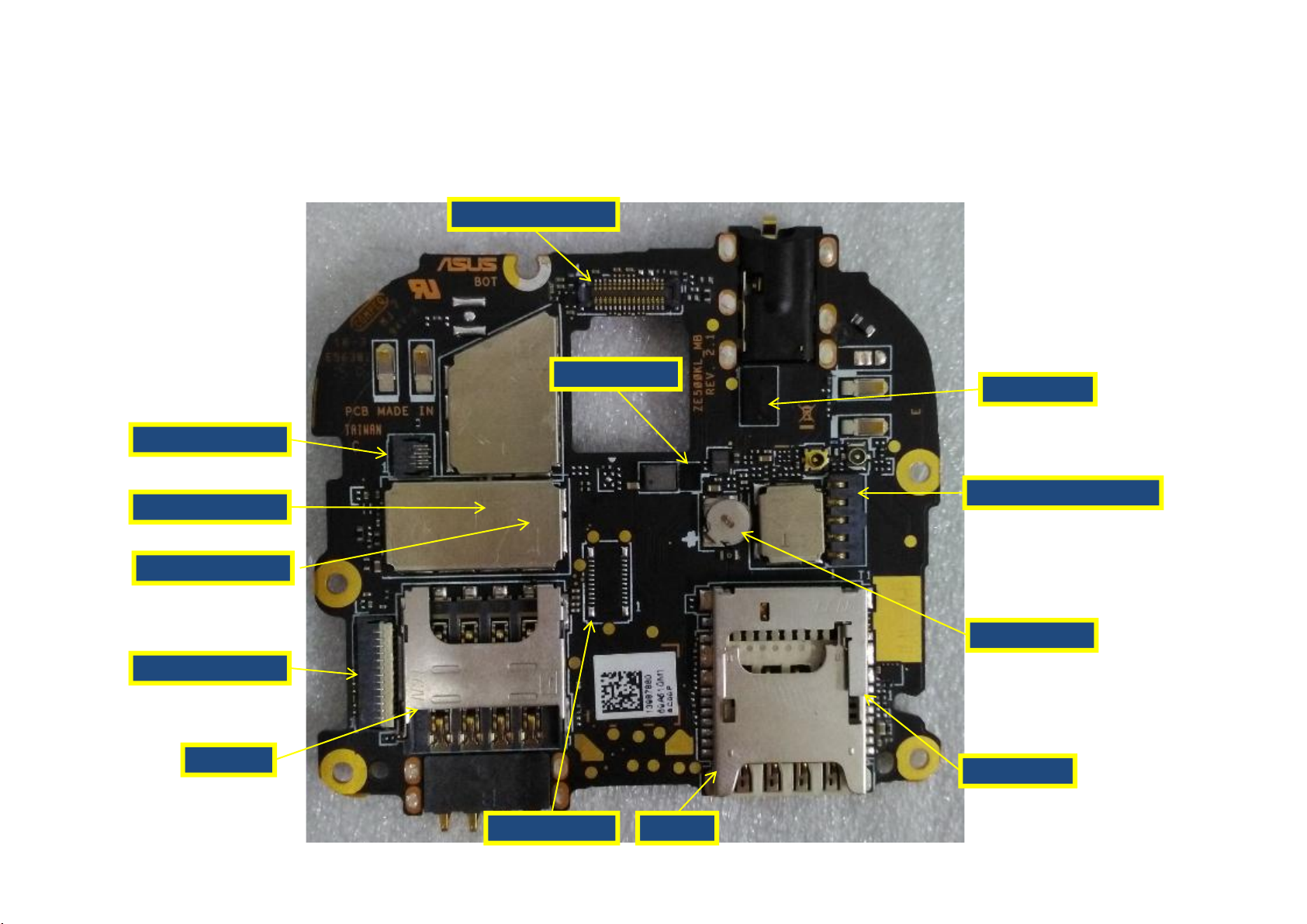
Assembly Chart BOTTOM VIEW
Laser Sensor
Touch FPC connector
13M/8M Rear Camera
FLASH Driver IC
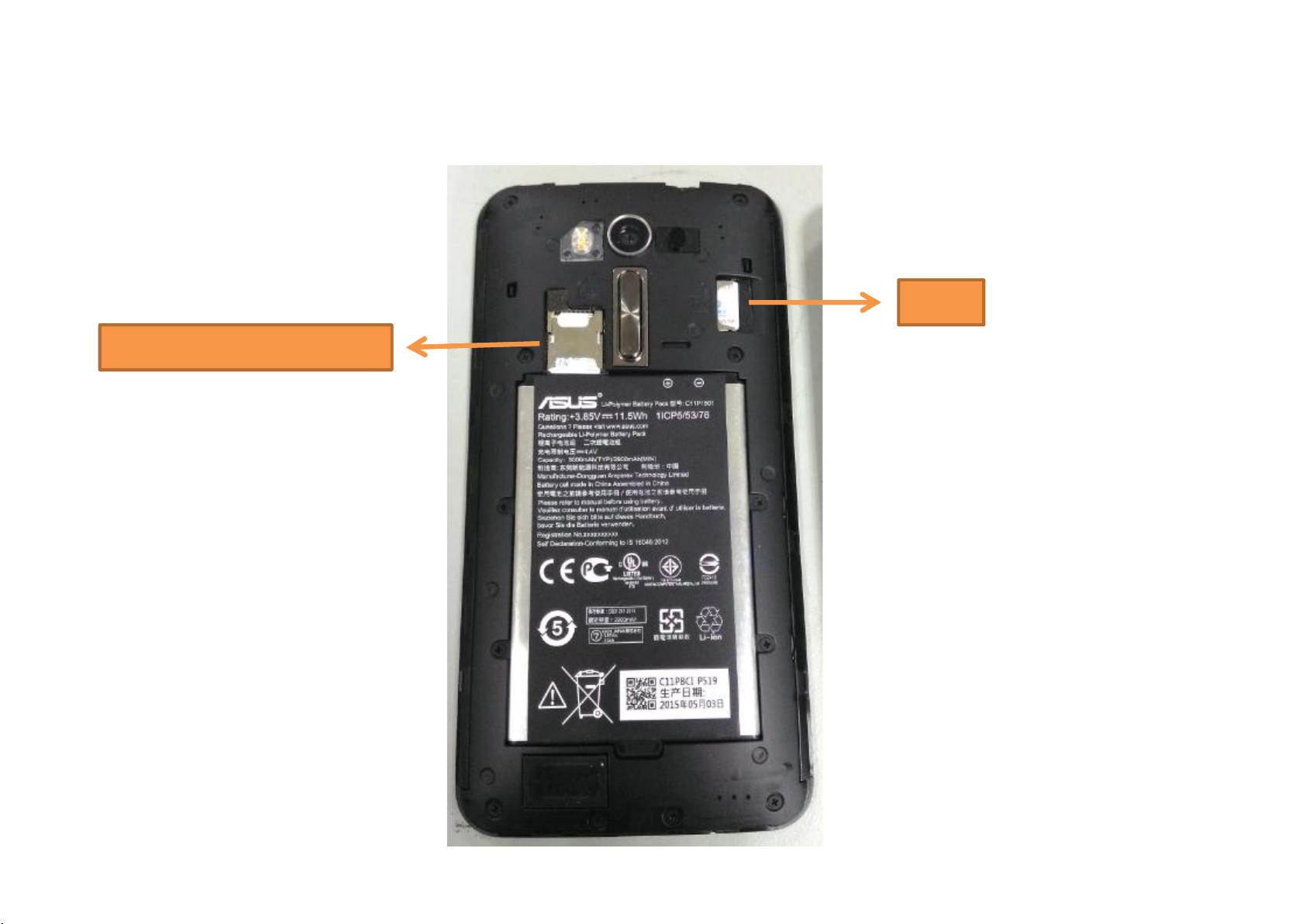
2ndSIM
1stSIMDebug connector
LCM FPC connector
RTC Super Cap
8 core external Buck
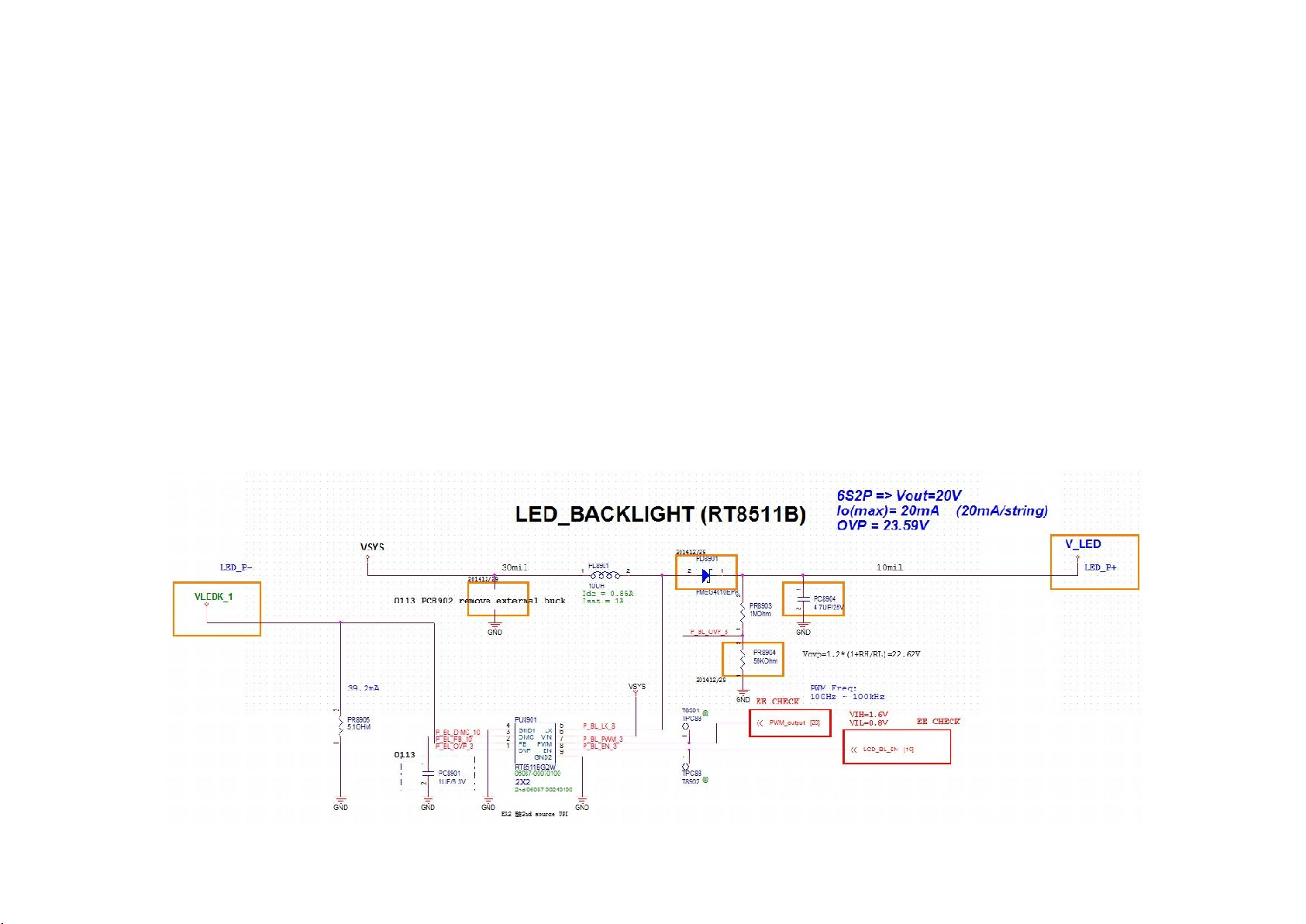
Backlight Driver IC
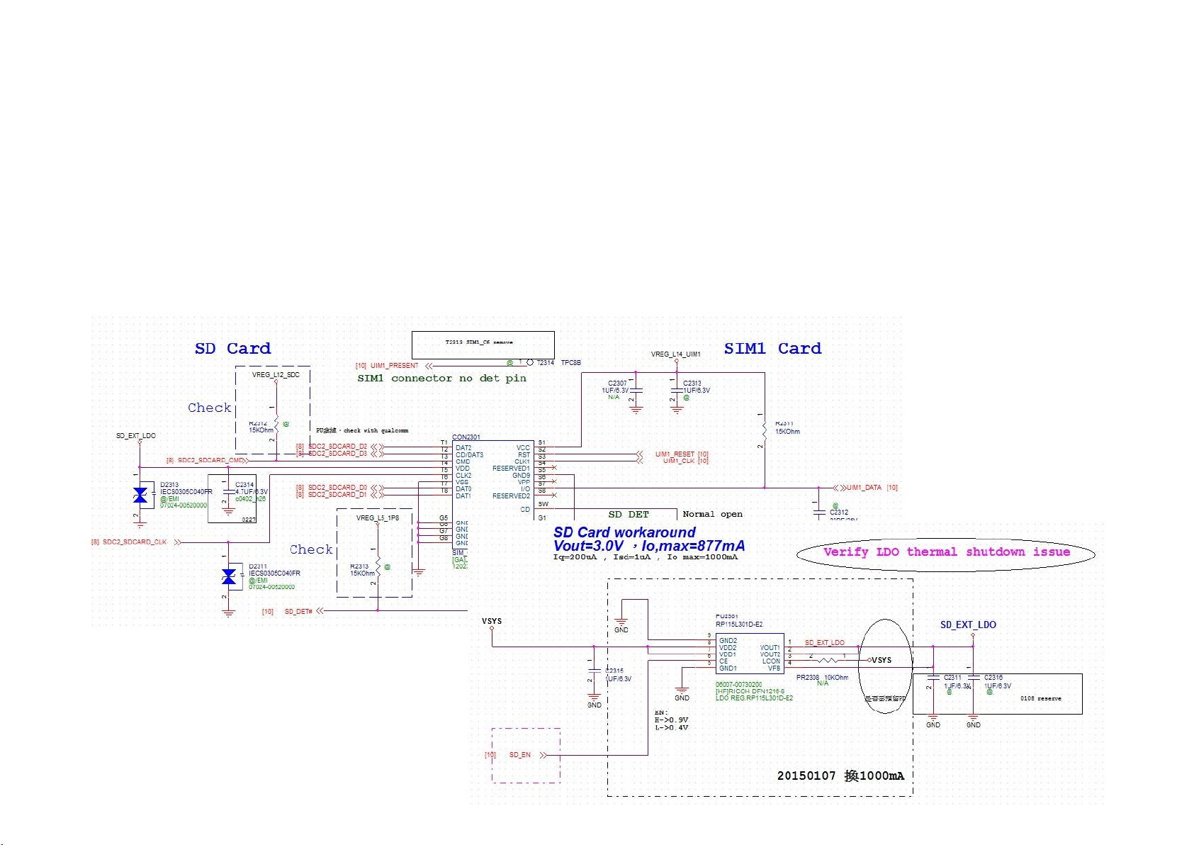
SD connector
Vol Key & FLASH LED Spring
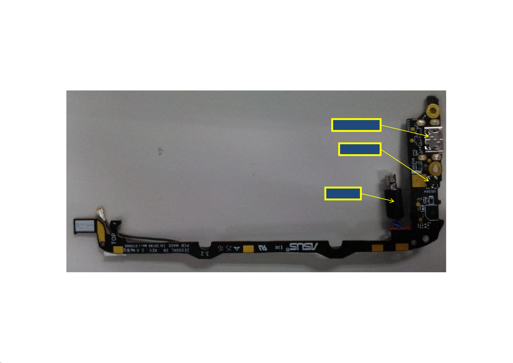
Assembly Chart TOP VIEW
Hall sensor
USB connector
Vibrator
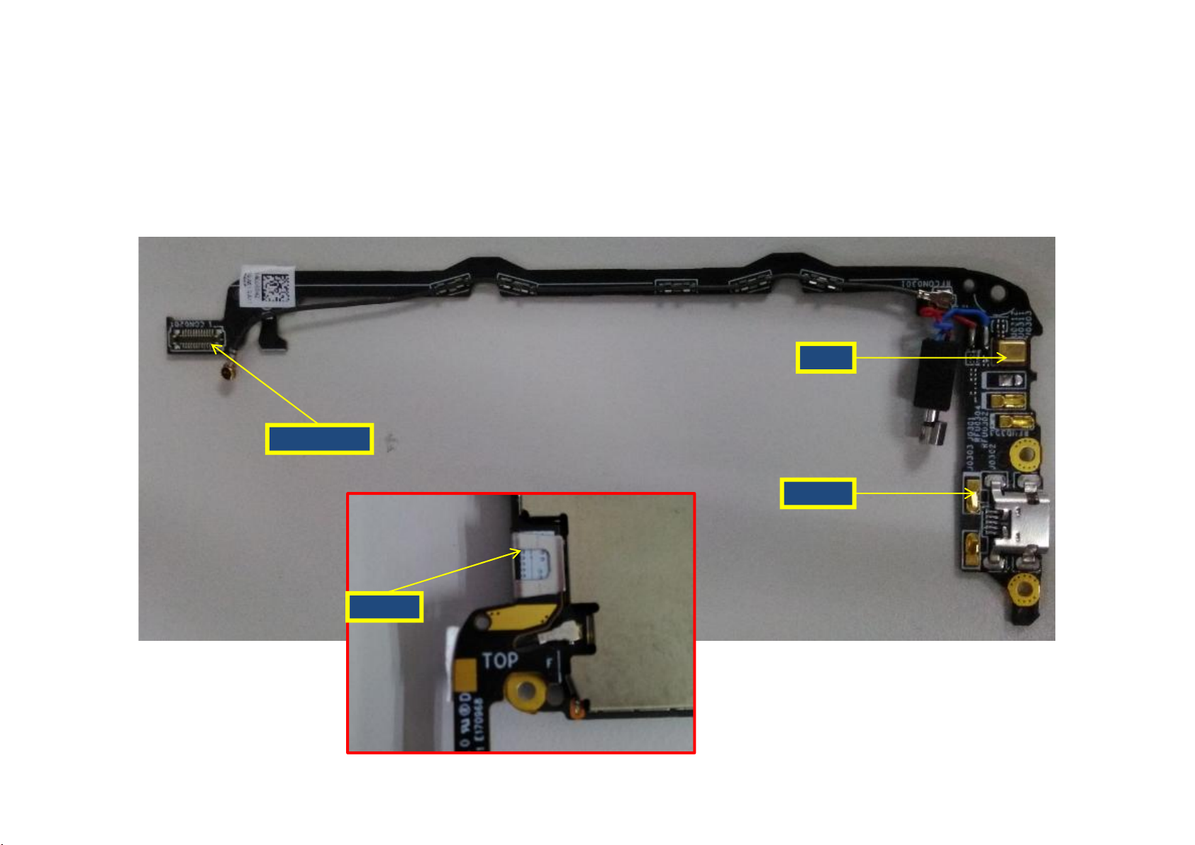
Assembly Chart
MIC
Speaker
IO connector
C型夾
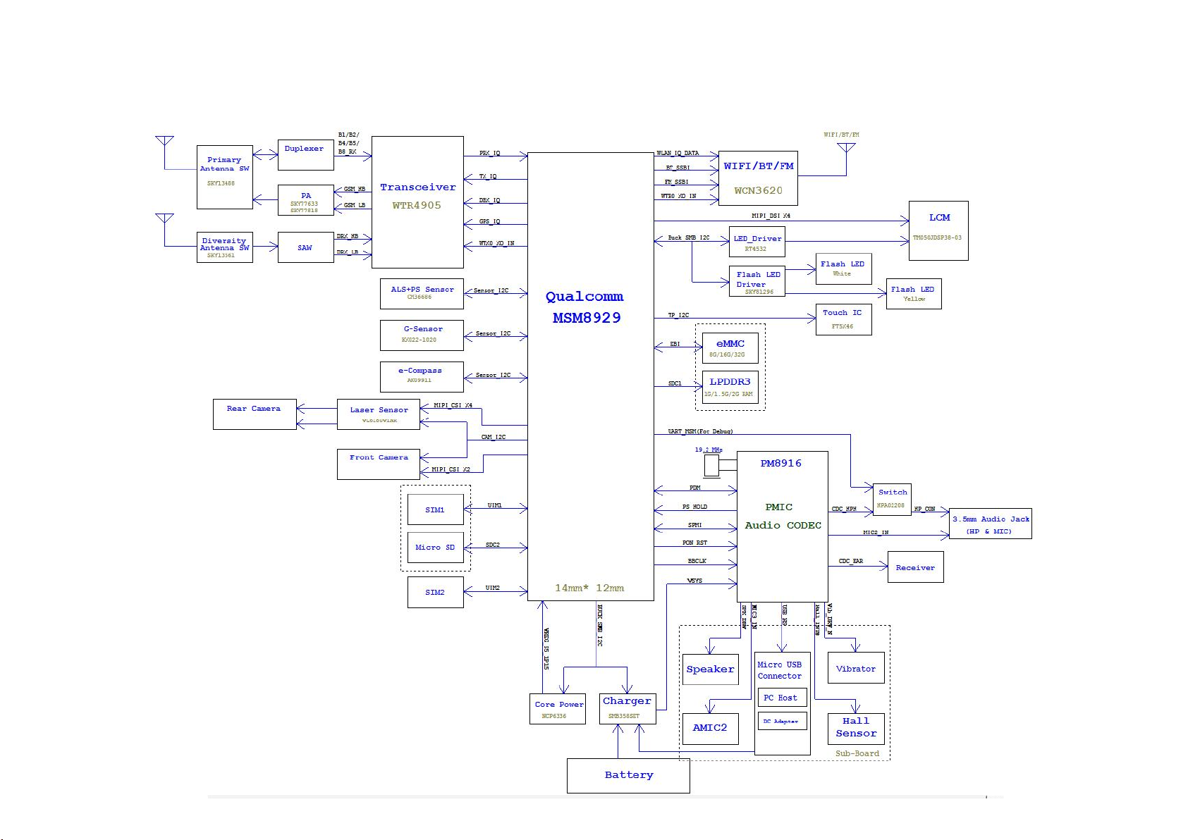
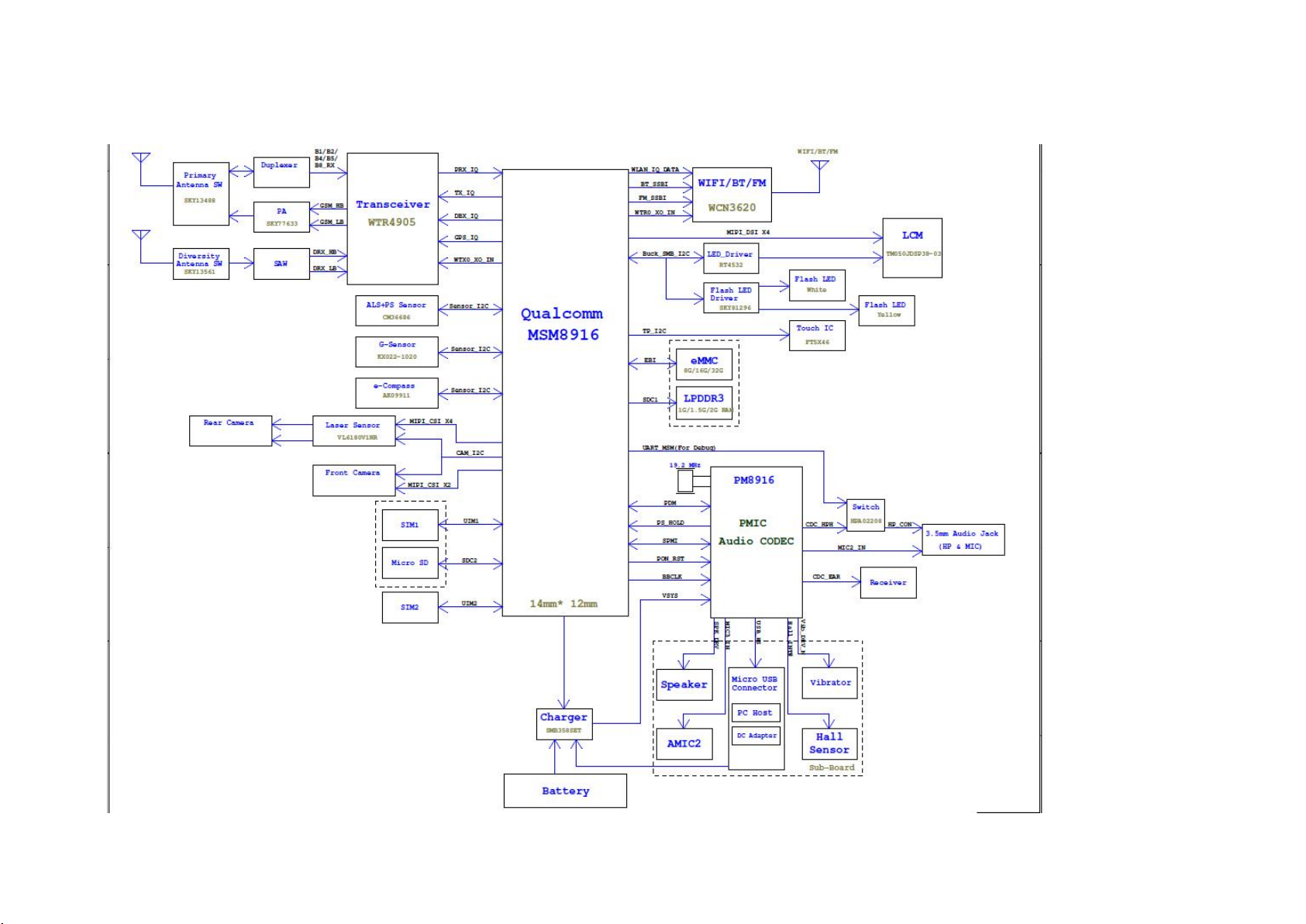
System Block Diagram
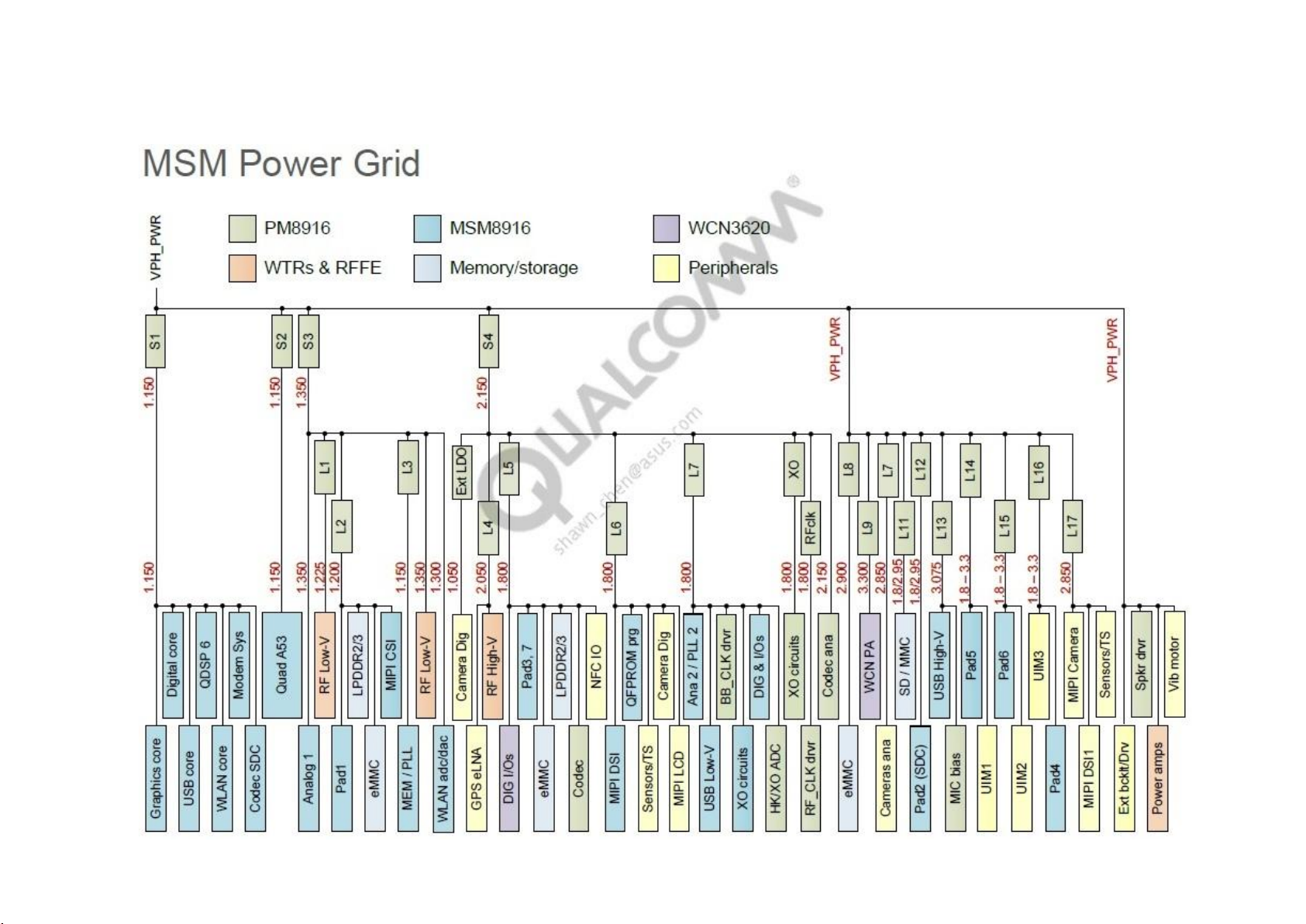
System Power Architecture

POWER ON SEQUENCE

Trouble shooting
1. No display
2. No Boot
3. Touch error
4. SD card error
5. P-Sensor/Light Sensor error
6. Camera error
1. No display
2. No Boot
3. Touch error
4. SD card error
5. P-Sensor/Light Sensor error
6. Camera error
No display
1. To confirm FPC has connected
2. Exchange Panel, check Panel is normal
3. When the boot, measure V_LED then the voltage is greater than 5V
4. Check LCD_BL_EN is high, PWM output has SPWM Input
5. To confirm PR8905 is 5.1 ohm
6. To confirm there is no damage PL8901 with PD8901

No Boot
1. ZE500KL not supported on automatic AC power, only charging mode
2. Confirm that the battery voltage is greater than 3.6V
3. To confirm Panel FPC has connected
4. To confirm KYPD_PWR_N pull low when you press Power Button
5. To confirm PS_Hold pull high (1.8V)
6. Check power(power on sequence) to-ground has no short circuit
7. Measure power(power on sequence), all power must have it
8. Please confirm XTAL must work
• When boot, USB is not recognized system
1. Check the sub board has buckled , C-clip is clamped on
2. Check if the sub board has bent/ Broken status
• The phone can not charge
1. It will be charged when the AC comes in, not need control signal. Check the adapter has
power and battery has plugged in, then the appearance of sub board is ok
2. Replace the PU 8101.
Other system status

Touch error
1. To confirm PC has not connected
2. Exchange Panel, To confirm TP is normal
3. To confirm has no voltage LCD_1V8 and VREG_L8_2P9
4. Check the I2C have no PU
5. Check TP_RST_N is high
6. When touch the screen, TP_INT_N has no high-low change
1. To confirm PC has not connected
2. Exchange Panel, To confirm TP is normal
3. To confirm has no voltage LCD_1V8 and VREG_L8_2P9
4. Check the I2C have no PU
5. Check TP_RST_N is high
6. When touch the screen, TP_INT_N has no high-low change
SD card error
1. Please confirm when you insert SD card, SD_DET # will pull low
2. Confirm SD_EXT_LDO has 3V output(If not, check the SD_EN is high)
3. Has 3V output but turn off, check DATA0 ~ 3 / CMD / CLK is
disconnected
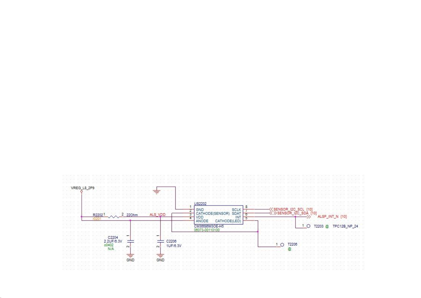
P-Sensor/Light Sensor error
1. Reassemble Rubber and retest
2. Check I2C is ok
3. Check VREG_L8_2P9 has Voltage
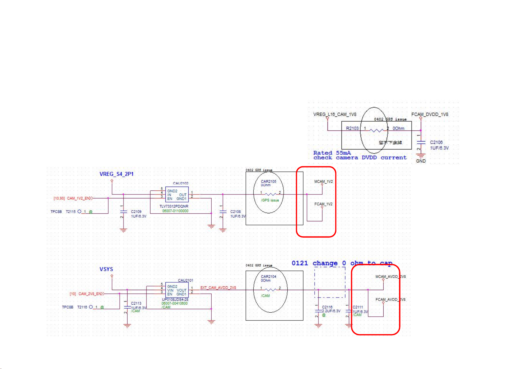
Camera error
1. Replace the Camera module and check module is normal
2. Open Camera, check FCAM_1V2,FCAM_AVDD_2V8 and
FCAM_DVDD_1V8 have power

ZE550KL
Introduction &Training
2015/6/8

ZE550KL Outline
• System Block Diagram
• Component and PCB Board Introduction
• Power On Sequence
• System Block Diagram
• Component and PCB Board Introduction
• Power On Sequence
• Equipment Requirement
• Trouble Shooting Guide

ZE550KL Outline
• System Block Diagram
• Component and PCB Board Introduction
• System Block Diagram
• Component and PCB Board Introduction
• Power On Sequence
• Equipment Requirement
• Trouble Shooting Guide
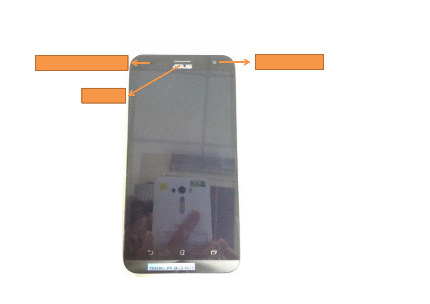
Outline Introduction (TOP)
FRONT CAMERA
Reciever
Proximity/ALPS Sensor
Outline Introduction (BOT)
REAR CAMERA
VOLUME UP
VOLUME DOWN
POWER BUTTON
HEADSET/HEADPHONEMIC 2
Flash led laser
SPEAKER
MIC 2
Sim 1 & SD Card combo
Sim 2
Outline Introduction (Take off the Back Cover)
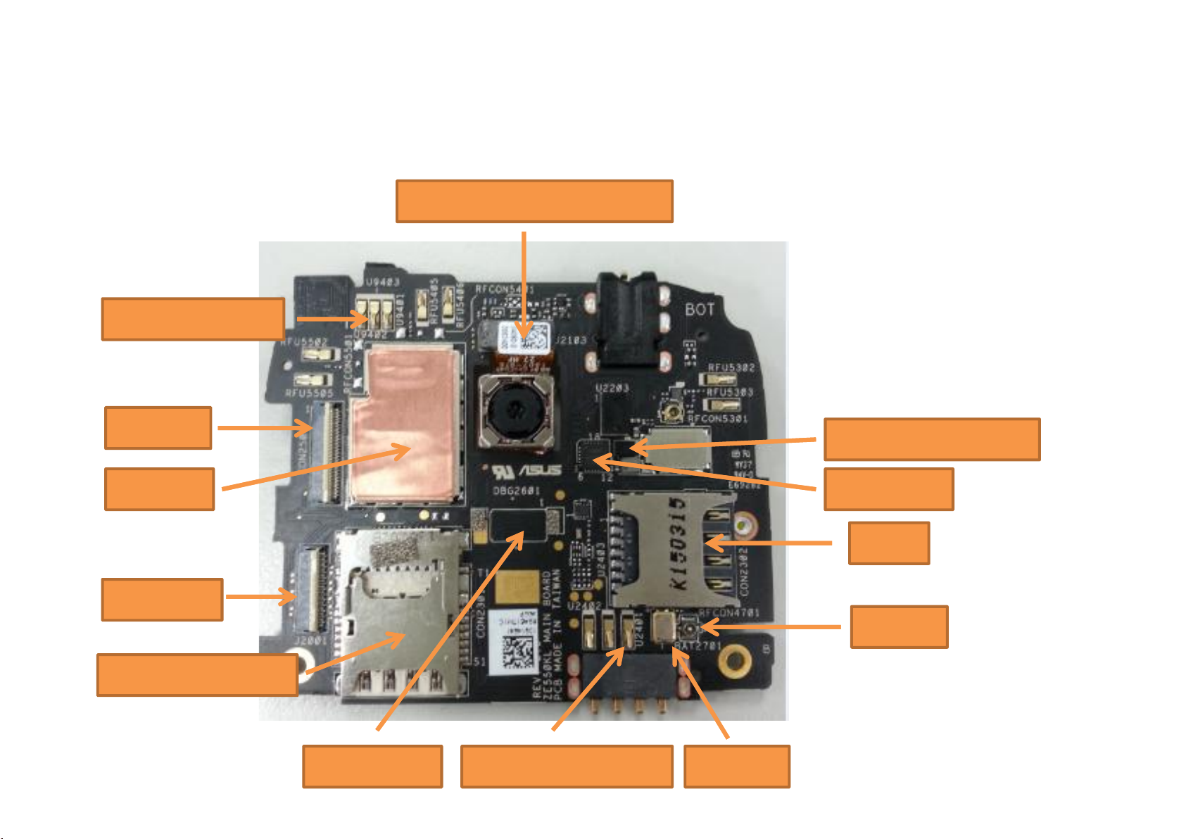
PCB Board Introduction (BOTTOM)
REAR CAEMRA 8M/13M
Flash led spring
LCD CON.
TP CON.
SIM 2
G-SENSOR
Debug con.
Touch IC
Volume key spring RTC BAT
SIM 1 & SD CARD
RF ANT
Flash LED Driver IC
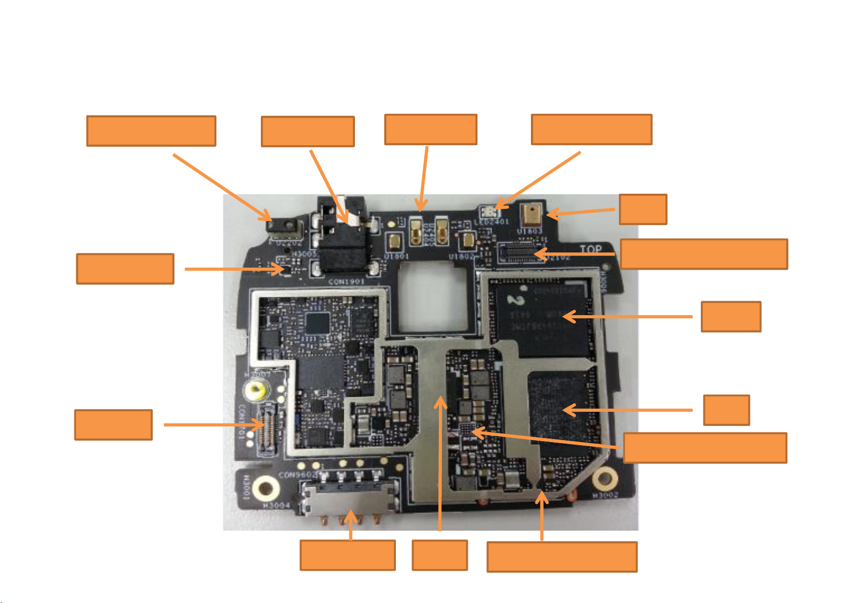
PCB Board Introduction (TOP)
Power key
ALS & P-Sensor
Audio jack
FRONT CAMERA 5M
R&G Indicator
E-Compass
MIC
BATT CON.
eMCP
I/O Con.
PMIC
SOC
Backlight driver IC
8939 External-buck

ZE550KL Outline
• System Block Diagram
• Component and PCB Board Introduction
• System Block Diagram
• Component and PCB Board Introduction
• Power On Sequence
• Trouble Shooting Guide
• Debug Skill

POWER ON SEQUENCE

ZE550KL Outline
• System Block Diagram
• Component and PCB Board Introduction
• System Block Diagram
• Component and PCB Board Introduction
• Power On Sequence
• Trouble Shooting Guide
• Debug Skill

Trouble Shooting Guide
1. 无法开机
2. 黑屏—可开机
3. Camera异常
1. 无法开机
2. 黑屏—可开机
3. Camera异常
4. p-sensor异常
5. E-compass异常
6. SD卡异常
7. Sim卡异常
8. TP 异常

Trouble Shooting Guide
无法开机
• 接上NB,打开装置管理员,确认是否有抓到device ;
• 量测 buck power是否起电( S1,S2,S3,S4 )
(1)buck power不起电 ,检查PMIC IC,以及周边零件制程;
(2) buck power起电 , 量测PS_hold信号,看是否上电并稳定高电平不掉;
• 接上NB,打开装置管理员,确认是否有抓到device ;
• 量测 buck power是否起电( S1,S2,S3,S4 )
(1)buck power不起电 ,检查PMIC IC,以及周边零件制程;
(2) buck power起电 , 量测PS_hold信号,看是否上电并稳定高电平不掉;
• 若ps_hold上电,尝试烧录image,无法烧录则需检查eMCP是否有Mount
完整
• 若ps_hold不上电,按照开机时序,用万用表量测各路power rail对地阻
抗是否正常;
• 若接近0 ohm ,确认以上Power是否发生对地short或者是有零件打反;
 Loading...