

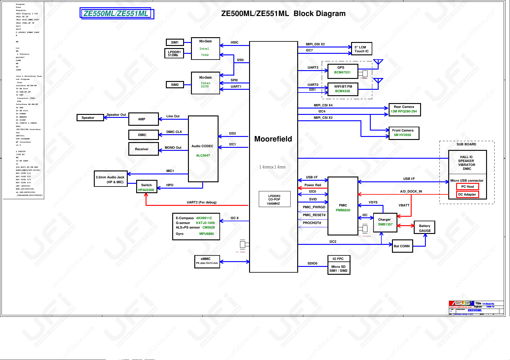
01.Block Diagram
02.Power Tree
03.Power Sequence
05.MOOREFIELD Display & CSI
06.MOOREFIELD GP IF
07.MOOREFIELD SDIO,eMMC,ULPI
08.MOOREFIELD JTAG,GP IF
09.CPU Power1
10.CPU Power2
13.MFD POP LPDDR3 DUMMY PART
16.IO CONN
19.eMMC
D D
21.LCM CONN
22.5M_CAM
23.Indicator
24.13M_CONN
25.Sensor & Vibrator
26.Codec ALC5647
27.Audio CONN
28.Key CONN
29.Micro SD
30.Debug CONN
31.EMI
32.Srew Holes & Shielding Case
39. BB Block Diagram
40. Power Tree
41. 223 Interface AP-BB-RF
42. XMM2230 BB Port
43. XMM2230 GSM_BT_RF
44. XMM2230 PMU
45. Debug Connector (TBD)
46. MICRO SIM
47. 7262 Interface AP-BB-RF
48. XMM7262 PMU
49. XMM7262 BB Port
50. XMM7262 POWER
51. XMM7262 MEMORY
C C
52. XMM7262 DIGRF
53. XMM7262 CONFIG & DEBUG
54. (RESERVE)
56. Wi-Fi/BT/GPS/FM Interface
57. BCM4343S
58. GPS_BCM47531
70. RF BLOCK DIAGRAM
71. BB - RF Interface
72. SMARTi4.5
73. FEMID
74. MMPA & PADCDC
75. 2G/3G/LTE RX
76. Div FEM
77. XMM2230 RF PART
78. GPS Ant
79. BCM4343S_WIFI_BT_FM ANT
81_PW_CHARGER(SMB347ET-2039Y)
84.PMU_SHADY COVE 1/4
85.PMU_SHADY COVE 2/4
86.PMU_SHADY COVE 3/4
87.PMU_SHADY COVE 4/4
89.PW_BL_LED (RT4532)
93.PW_CAMERA_LDO(UP0108)
94.PW_Flash LED(SKY81296)
96.PW_BAT_CON&GAUGE(UG3105PDUC )
B B
A A
5
ZE550ML/ZE551ML
Speaker
Speaker Out
3.5mm Audio Jack
(HP & MIC)
AMP
DMIC
Receiver
Switch
HPA02208
4
3
2
1
ZE500ML/ZE551ML Block Diagram
SIM1
LPDDR1
512Mb
SIM2
Line Out
DMIC CLK
MONO Out
MIC1
HPO
UART2 (For debug)
G-sensor
ALS+PS sensor CM3628
Gyro MPU6880
Modem
Intel
7262
Modem
Intel
2230
Audio CODEC
ALC5647
AK09911C
KXTJ2-1009
eMMC
PK size:12x13 mm
HSIC
SPI0
UART1
I2S2
I2C1
I2C 8E-Compass
I2S0
19.2MHz
Moorefield
14mmx14mm
LPDDR3
CO-POP
1600MHZ
MIPI_DSI X2
I2C7
UART2
UART0
I2S1
MIPI_CSI X4
I2C4
MIPI_CSI X2
USB I/F
Power Rail
I2C0
SVID
PMIC_PWRGD
PMIC_RESET#
PROCHOT#
SDIO0
GPS
BCM47531
WIFI/BT/FM
BCM4339
PMIC
PMB6830
I2C2
IO FPC
Micro SD
SIM1 / SIM2
5" LCM
Touch IC
26MHz
I2C
32.768KHz
VSYS
Charger
SMB1357
Rear Camera
13M RFQ290-294
Front Camera
5M HV2056
USB I/F
A/D_DOCK_IN
VBATT
Bat CONN
Battery
GAUGE
SUB BOARD
HALL IC
SPEAKER
VIBRATOR
DMIC
Micro USB connector
PC Host
DC Adapter
Title :
Title :
Title :
01.Block Diagram
01.Block Diagram
01.Block Diagram
Engineer:
Eddie Yang
Engineer:
Eddie Yang
Engineer:
ASUSTeK COMPUTER INC. EPAD
ASUSTeK COMPUTER INC. EPAD
ASUSTeK COMPUTER INC. EPAD
Size Project Name
Size Project Name
Size Project Name
ZE550ML
ZE550ML
ZE550ML
D
D
D
Date: Sheet of
Date: Sheet of
5
4
3
2
Date: Sheet of
1
Eddie Yang
1 99Wednes day, February 11 , 2015
1 99Wednes day, February 11 , 2015
1 99Wednes day, February 11 , 2015
Rev
Rev
Rev
1.0
1.0
1.0

ZE550ML/ZE551ML
Trouble Shooting Guide
Content:
01. No Display
02. Touch Test
03. Display Can Not Rotate
04. E-compass Test
05. Front Camera Test
06. Can Not Charge
07. Headset Test
08. Speaker Test
09. MIC Test
10. SIM Test
11. Rear Camera Test
12. Miro SD Card Test
13. Vibrator Test
14. Receiver Test
15. Proximity Sensor& Light Sensor Test
16. Volume & Power Button Test
17. Can’t power on

1.1 No Display
Page:21
a. Check the battery power is sufficient, plug USB cable to boot test when charging.
b. Check if FPC is properly connected and not damaged, re-assemble LCD FPC and check display.
c. Swap LCD Module and check display.
d. Check the following if no output voltage or short circuit to GND & ground impedance is abnormal (compared
with the normal board).
VCC_LCD
V_1P80_VDD1
e. Check
MIPI_LCM_DP0/MIPI_LCM_DN0/MIPI_LCM_DP1/MIPI_LCM_DN1/MIPI_LCM_DP2/MIPI_LCM_DN2/MIPI_LCM
_DP3/MIPI_LCM_DN3/MIPI_LCM_CLKP/MIPI_LCM_CLKN
Ground impedance is abnormal (compared with the normal board) & has a signal output.
f. To confirm the missing solder after reheat U1.
1.2 Touch Panel Test
Page:20
a. Check if FPC is properly connected and not damaged, re-assemble FPC and check function is ok or not.
b. Swap touch panel and check touch panel is ok or not.
c. Check the CON2001 is ok or not and not damaged.
d. Check the following if no output voltage or short circuit to GND & ground impedance is abnormal (compared
with the normal board).
e. Check V_1P80_VDD1 voltage level of 1.8V; V 3P30 VDD3 voltage level of 3.3V.
f. Check I2C_0 SDA, I2C_0 SCL whether the voltage level of 1.8V and has a signal output.
1.3 Display Can Not Rotate
Page:25
a. Enable“Auto-rotateScreen”inSettings,then test again.
b. Check the U2502 or U2504 is ok or not and not damaged.
c. Check whether the peripheral parts missing, broken.
d. Check the I2C 8 SCL, I2C 8 SDA voltage of 1.8V.
e. Check the I2C 8 SCL, I2C 8 SDA has a signal output.
f. Reheat U2502 or U2504 to confirm whether missing solder.
g. Above all no abnormal replace U2502 or U2504

1.4 E-compass Test
Page:25
a. Check the U2501 or U2505 is skewed and broken.
b. Check whether the peripheral parts missing, broken.
c. Check the I2C 8 SDA, I2C 8 SCL voltage of 1.8V.
d. Check the V_1P80_VDD1 is a voltage level of 1.8V, Check the V_VPROG3_2V9 is a voltage level of 2.9V.
e. Reheat U2501 or U2505to confirm whether missing solder.
f. Above all no abnormal replaceU2501 or U2505.
1.5 Front Camera(5M) Test
Page:22
a. Check the Camera Module is properly connected and not damaged, re-assemble Camera Module and check
function.
b. Check the CON2201 is skewed and broken.
c. Check whether the peripheral parts missing, broken.
g. Swap Camera Module and check Camera Module is ok or not.
d. Check the SUB_CAM_2V8_SEN is a voltage level of 2.8V,If there is no voltage, check the R 2405.
e. Check the SUB_CAM_1V8 is a voltage of 1.8V.
f. Check the SUB_CAM_1V2 is a voltage of 1.2V.
g. Check the I2C_4_SDA, I2C_4_SCL is a voltage of 1.8V.
1.6 Can Not Charge
Page:81
a. Check the PU8101 is skewed and broken.
b. Check whether the peripheral parts missing, broken.
c. Check the SUB BOARD and IOFPCis ok or not.
d. According to x-ray for PU8101.
e. Reheat U8101
1.7 Headset Test
Page:27
a. Check the J2701 is skewed and broken.
b. Check whether the peripheral parts missing, broken.
c. Confirm U2601 & peripheral components if there are missing parts, short circuit, broken.
d. According to x-ray for U2601.
e. Reheat U2601

1.8 Speaker Test
Page:26
a. Confirm CON1601 if there are missing parts, short circuit, broken.
b. Confirm peripheral components if there are missing parts, broken.
c. Check the SPEAKER and IOFPC is ok or not
d. Confirm U2609 peripheral components are normal.
1.9 MIC Test
Page:26
a. Check if the U2602 is skew, missing solder or damage.
b. Confirm peripheral components if there are missing parts, broken.
c. Use a magnifying glass to check radio MIC hole if there is blocked.
d. Exchange U2602.
1.10 SIM Test
Page:60
a. Check if the IO FPC plugged in properly, skew or damaged, missing parts.
b. Check IOFPC is ok or not.
c. To confirm the VSIM 1_VAR and VSIM are 1.8.
d. Are you sure Modem version can be read with.
e. According to two Modem X-ray.
1.11 Rear Camera(13M) Test
Page:24
a. Check the Camera Module is properly connected and not damaged, re-assemble Camera Module and check
function.
b. Check if the CON2401 is skew, missing solder or damage.
c. Swap Camera Module and check Camera Module is ok or not.
d. Confirm peripheral components if there are missing parts, broken.
e. Check the V_2P8_CAM is a voltage level of 2.8V, If there is no voltage, check the R2401.
f. Check the V_2P80_VCM is a voltage level of 2.8V, If there is no voltage, check the R2403.
g. Check the V_1P2_DVDD is a voltage of 1.2V.
h. Check the V_1P80_DVDD is a voltage of 1.8V.
i. Check the I2C_4_SCL, I2C_4_SDA is a voltage of 1.8V.

1.12 Miro SD Card Test
Page:29
a. Check if the Micro SD Card plugged in properly.
b. Check if IO FPC is properly connected and not damaged, skew, missing solder or damage.
c. Confirm U2902 & peripheral components if there are missing parts, broken.
d. Check the V_3P30_SW is a voltage of 3.3V.
e. Check the Bias voltage of SDIO0_DATA0, SDIO0 DATA1, SDIO0 DATA2, SDIO0 DATA3, SDIO0_CMD, SDIO0_CLK
are normal, If the Bias voltage is not normal, Reheat U1, Confirm the U1 missing solder caused the signal can
not be delivered.
1.13 Vibrator Test
Page:18
a. Check if the sub board has skew, missing solder or damage.
b. Confirm peripheral components if there are missing parts, broken.
c. Check IOFPC is ok or not.
d. Confirm the front cover don’t affect the vibrator.
1.14 Receiver Test
Page:26
a. Confirm the RECEIVER press the main board.
b. Confirm there is a screen protectoron theTP Module.
1.15 Proximity Sensor& Light Sensor Test
Page:25
a. Check if the U2503 and LED2501 is skew, missing solder or damage.
b. Confirm peripheral components if there are missing parts, broken.
c. Check the I2C_8_SCL, I2C_8_SDA is a voltage of 1.8V; V_VPROG3_2V9 is a voltage of 2.9V.
1.16 Power Button Test
Page:28
a. Check if the SW2801 is skew, missing solder or damage.
b. Check the SW2801 is stuck or not.

1.17 No boot
Page:81
a. Check if the VSYS short circuit to GND.
Page:84
a. Check if the V_VCC0、V_VCC1、VNN、VNNAON short circuit to GND.
Page:85
a. Check if the V_1P80_VDD1、V_1P24_VDD2、V_3P3_VDD3 short circuit to GND.
Page:6
a. Check the PMIC_POWERGOOD、PMIC_RESET_N is a voltage of 3.3V.
Page:8
a. Check the VOLUME_DOWN_SOC is a voltage of 1.8V, Check if the Q0801 has Anti-polarity.
Page:19
a. Check the eMMC_DATA_0~7、eMMC_CMD、eMMC_RST_N is a voltage of 1.8V, eMMC CLK has a vibrating
Page:13
a. If the U1301 no displacement, According to X RAY to confirm U1301 and U1 without missing solder or bridging.
 Loading...