

Page 1

INSTALLATION & REPLACEMENT
Installation & Replacement
Follow the individual procedures to perform the notebook’s
installation and replacement of various major components.
Z90R Series Notebook is a product balanced, novelty and mobility in an elegantly
designed housing. The key installable and replaceable items include the Memory,
CPU module, MINIPCI Wireless Lan module, Optical drive module and HDD module.
Be sure to follow the safety instructions described from the start to safeguard the
notebook against any potential damages.
This chapter includes the following items:
• Appropriate Tools
• Precautions
• Memory Installation & Replacement
• CPU Module Installation & Replacement
• MINIPCI Wireless Lan Module Installation & Replacement
• Optical Drive Module Installation & Replacement
• HDD Module Installation & Replacement
1
Page 2
INSTALLATION & REPLACEMENT
TOOLS
CROSS
SCREW-
DRIVER
FLATHEAD
SCREW-
DRIVER
TWEEZERS
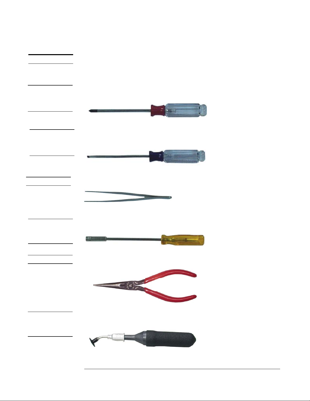
Appropriate Tools
The illustrations below show the appropriate tools that should be used for the
notebook’s service and repair.
Phillips-head Screwdriver
Use a Phillips-head screwdriver to fasten/remove the K- or B-typed screws.
Single-Slotted Screwdriver
Use a single-slotted screwdriver to lock/unlock the flexible cable connector locks
Tweezers
Use a pair of tweezers to remove/insert flexible cables.
SPACER
SCREW-
DRIVER
PLIERS
VACUUM
HANDLING
TOOL
Spacer Screwdriver
Use a spacer screwdriver to fasten/remove spacer screws or hex screws.
Pliers
Use a pair of pliers to handle regular cables.
Vacuum Handling Tool
Use Vacuum handling tool to handle CPU.
2
Page 3
INSTALLATION & REPLACEMENT
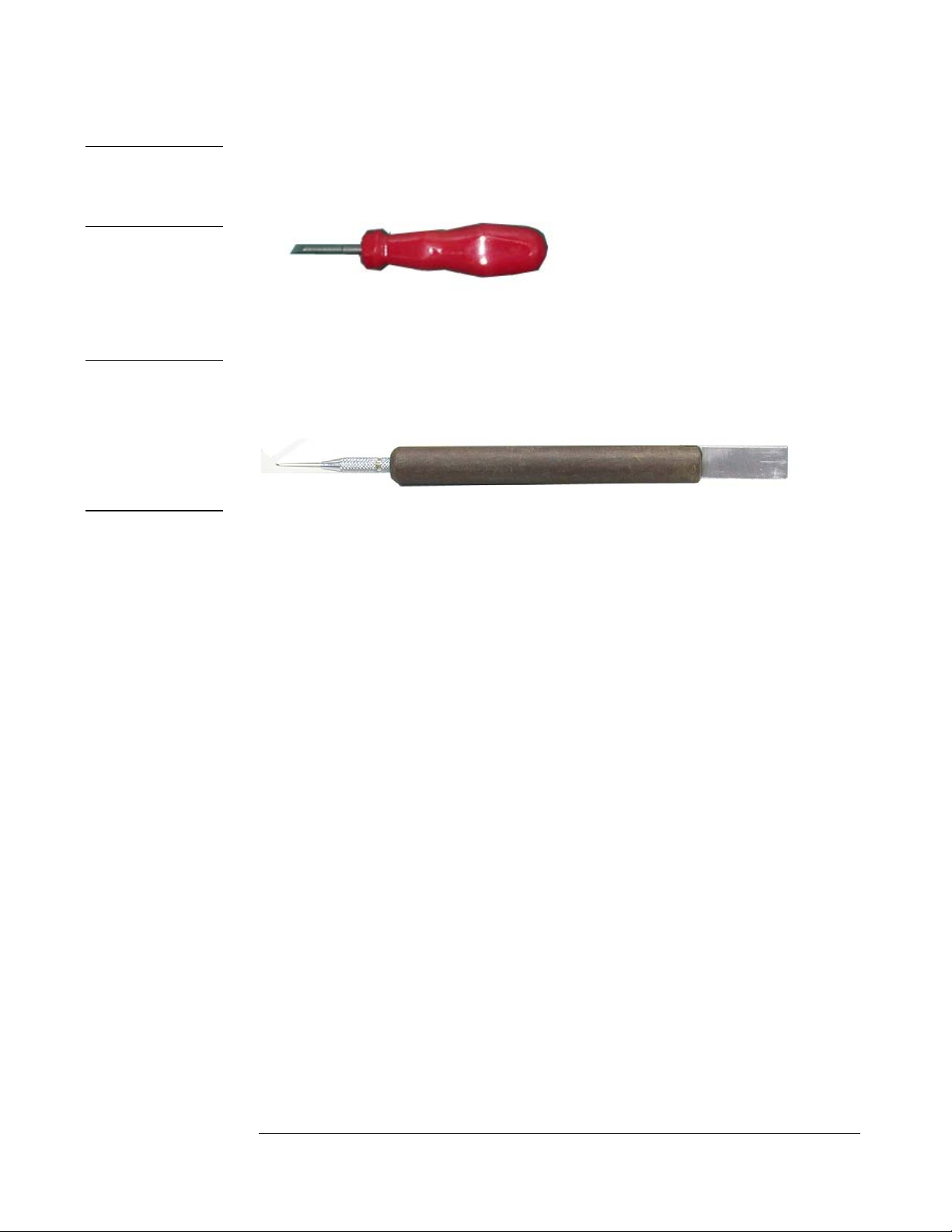
MOLEX
CPU SOCKET
TOOL
INSERTION
AND
EXTRACTION
TOOL FOR
FPC
CONNECTOR
Molex CPU Socket Tool
Use Molex CPU Socket tool to lock/unlock the Molex socket of CPU.
Width: 4.00mm Depth: 0.45+/-0.1mm The angle of tip: approximate 9 degree
Insertion and extraction tool for FPC connector
Use insertion and extraction tool for FPC connector to handle locking and unlocking
of FPC connectors.
3
Page 4

INSTALLATION & REPLACEMENT
CAUTIONS
Precautions
Before you perform any service and/or repair on the notebook, please follow the steps
below first.
1. Be sure that the notebook is powered down.
2. Disconnect the AC plug from the left side of the notebook (on the illustration
below).
3. Turn the notebook over. Unlock and hold the 2 latches, and remove the battery .
4. Remove all rings, watches and any other metal objects from your hands.
5. Always wear a ground strap on your hand to protect the notebook from static
discharge.
4
Page 5

INSTALLATION & REPLACEMENT
MEMORY
Memory Upgrade
Two SODIMM socket supported for expansion up to 1024MB total
(512MB DDR SO-DIMM x2).
First, remove AC-power and battery.
Upgrading memory
1. Find the memory socket under the Keyboard (Fig1) and bottom case (Fig2)
as following photos and upgrade memory by the process of item2 and item3.
Fig1 Fig2
2. If there is an existing memory, remove it by opening the latches (no. 1), which will
pop the module up to a 45° angle, and then pulling out the module in that angle
(no. 2).
2
1
1
3. Insert new memory at the same 45° angle (no. 3) and press down (no. 4) until it
clicks into the latches.
4
3
4
5
Page 6

INSTALLATION & REPLACEMENT
Pin 1
2. Put the CPU thermal pad on the CPU diode.
3. Place the CPU Heat sink module onto it.
4. Secure 4 screws(M2*6L) in sequence.
5. Connect the FAN cable and install the CPU fan in the proper location. /
Finally, Secure 2 screws(M2*6L) here .
6. Secure 1 screw here to fix cover.
6
Page 7

MINIPCI
WIRELESS
LAN MODULE
INSTALL
INSTALLATION & REPLACEMENT
MINIPCI Wireless Lan Module Installation & Replacement
The illustrations below show how to assemble and install the MINIPCI
Wireless Lan Module into the notebook.
1. Take MINIPCI Wireless Lan Module.
2. Connect the black main antenna cables to main pole and connect white
auxiliary antenna cable to auxiliary pole.
3. Install the MINIPCI Wireless Lan module board well.
4. Secure one screw here to fix the cover.
Optical
MODULE
INSTALL
Optical Drive Module Installation & Replacement
The illustrations below show how to assemble and install the Optical
drive module into the notebook.
1. Push the Optical drive module into the socket.
2. Secure 2 screw(M2*4L) here to fix it.
3. Place the rubber well here.
7
Page 8

INSTALLATION & REPLACEMENT
HDD/
BATTERY
INSTALL
HDD MODULE
INSTALL
HDD Module Installation & Replacement
The illustrations below show how to install the HDD module and into the notebook.
Install HDD Module
The illustrations below show how to install HDD module.
1. Slide the HDD to connect to its connector.
2. Secure 3 screws (M2.5*8L)here to fix the HDD.
8
 Loading...