

Page 1

E8655
First Edition
November 2013
Notebook PC
E-Manual
Page 2

2
Notebook PC E-Manual
COPYRIGHT INFORMATION
No part of this manual, including the products and software described in it, may be reproduced,
transmitted, transcribed, stored in a retrieval system, or translated into any language in any form or by
any means, except documentation kept by the purchaser for backup purposes, without the express
written permission of ASUSTeK COMPUTER INC. (“ASUS”).
ASUS PROVIDES THIS MANUAL “AS IS” WITHOUT WARRANTY OF ANY KIND, EITHER EXPRESS OR IMPLIED,
INCLUDING BUT NOT LIMITED TO THE IMPLIED WARRANTIES OR CONDITIONS OF MERCHANTABILITY OR
FITNESS FOR A PARTICULAR PURPOSE. IN NO EVENT SHALL ASUS, ITS DIRECTORS, OFFICERS, EMPLOYEES
OR AGENTS BE LIABLE FOR ANY INDIRECT, SPECIAL, INCIDENTAL, OR CONSEQUENTIAL DAMAGES
(INCLUDING DAMAGES FOR LOSS OF PROFITS, LOSS OF BUSINESS, LOSS OF USE OR DATA, INTERRUPTION
OF BUSINESS AND THE LIKE), EVEN IF ASUS HAS BEEN ADVISED OF THE POSSIBILITY OF SUCH DAMAGES
ARISING FROM ANY DEFECT OR ERROR IN THIS MANUAL OR PRODUCT.
Products and corporate names appearing in this manual may or may not be registered trademarks or
copyrights of their respective companies, and are used only for identication or explanation and to the
owners’ benet, without intent to infringe.
SPECIFICATIONS AND INFORMATION CONTAINED IN THIS MANUAL ARE FURNISHED FOR INFORMATIONAL
USE ONLY, AND ARE SUBJECT TO CHANGE AT ANY TIME WITHOUT NOTICE, AND SHOULD NOT BE
CONSTRUED AS A COMMITMENT BY ASUS. ASUS ASSUMES NO RESPONSIBILITY OR LIABILITY FOR ANY
ERRORS OR INACCURACIES THAT MAY APPEAR IN THIS MANUAL, INCLUDING THE PRODUCTS AND
SOFTWARE DESCRIBED IN IT.
Copyright © 2013 ASUSTeK COMPUTER INC. All Rights Reserved.
LIMITATION OF LIABILITY
Circumstances may arise where because of a default on ASUS’ part or other liability, you are entitled to
recover damages from ASUS. In each such instance, regardless of the basis on which you are entitled to
claim damages from ASUS, ASUS is liable for no more than damages for bodily injury (including death)
and damage to real property and tangible personal property; or any other actual and direct damages
resulted from omission or failure of performing legal duties under this Warranty Statement, up to the
listed contract price of each product.
ASUS will only be responsible for or indemnify you for loss, damages or claims based in contract, tort or
infringement under this Warranty Statement.
This limit also applies to ASUS’ suppliers and its reseller. It is the maximum for which ASUS, its suppliers,
and your reseller are collectively responsible.
UNDER NO CIRCUMSTANCES IS ASUS LIABLE FOR ANY OF THE FOLLOWING: (1) THIRD-PARTY CLAIMS
AGAINST YOU FOR DAMAGES; (2) LOSS OF, OR DAMAGE TO, YOUR RECORDS OR DATA; OR (3) SPECIAL,
INCIDENTAL, OR INDIRECT DAMAGES OR FOR ANY ECONOMIC CONSEQUENTIAL DAMAGES (INCLUDING
LOST PROFITS OR SAVINGS), EVEN IF ASUS, ITS SUPPLIERS OR YOUR RESELLER IS INFORMED OF THEIR
POSSIBILITY.
SERVICE AND SUPPORT
Visit our multi-language web site at http://support.asus.com
Page 3

Table of Contents
About this manual .....................................................................................................6
Conventions used in this manual .............................................................................7
Icons ....................................................................................................................................7
Typography ....................................................................................................................... 7
Safety precautions.....................................................................................................8
Using your Notebook PC .............................................................................................. 8
Caring for your Notebook PC .....................................................................................9
Proper disposal ................................................................................................................ 10
Chapter 1: Hardware Setup
Getting to know your Notebook PC ...................................................................12
Top View ............................................................................................................................. 12
Bottom ................................................................................................................................ 16
Right Side ..........................................................................................................................17
Left Side .............................................................................................................................19
Front Side ..........................................................................................................................20
Chapter 2: Using your Notebook PC
Getting started ...........................................................................................................22
Charge your Notebook PC. ..........................................................................................22
Lift to open the display panel. ....................................................................................25
Press the power button. ...............................................................................................25
Gestures for the touchpad .....................................................................................26
Using the keyboard ...................................................................................................33
Function keys ................................................................................................................... 33
Function keys for ASUS Apps ..................................................................................... 34
Windows® 8.1 keys ......................................................................................................... 35
Multimedia control keys (on selected models) .................................................... 35
Numeric keypad (on selected models) ................................................................... 36
Using the optical drive .............................................................................................37
Notebook PC E-Manual
3
Page 4

4
Notebook PC E-Manual
Chapter 3: Working with Windows® 8.1
Starting for the first time .........................................................................................40
Windows® 8.1 lock screen ........................................................................................40
Windows® UI ................................................................................................................41
Start screen .......................................................................................................................41
Hotspots ............................................................................................................................. 42
Start button ......................................................................................................................45
Customizing your Start screen ................................................................................... 47
Working with Windows® apps ...............................................................................48
Launching apps ............................................................................................................... 48
Customizing apps ........................................................................................................... 48
Closing apps ..................................................................................................................... 49
Accessing the Apps screen .......................................................................................... 50
Charms bar ........................................................................................................................ 52
Snap feature .....................................................................................................................54
Other keyboard shortcuts ......................................................................................56
Connecting to wireless networks ........................................................................58
Wi-Fi ..................................................................................................................................... 58
Bluetooth .......................................................................................................................... 59
Airplane mode ................................................................................................................. 61
Connecting to wired networks ............................................................................. 62
Configuring a dynamic IP/PPPoE network connection ....................................62
Configuring a static IP network connection .........................................................63
Turning your Notebook PC off ..............................................................................64
Putting your Notebook PC to sleep .........................................................................65
Chapter 4: Power-on Self Test (POST)
The Power-on Self Test (POST ) ..............................................................................68
Using POST to access BIOS and Troubleshoot...................................................... 68
BIOS ................................................................................................................................68
Accessing BIOS ................................................................................................................68
BIOS Settings .................................................................................................................... 69
Page 5

Troubleshoot ...............................................................................................................79
Refresh your PC ...............................................................................................................79
Reset your PC ...................................................................................................................80
Advanced options .......................................................................................................... 81
Appendices
DVD-ROM Drive Information (on selected models) ........................................... 84
Blu-ray ROM Drive Information (on selected models) ....................................... 86
Internal Modem Compliancy...................................................................................... 86
Overview ............................................................................................................................ 87
Network Compatibility Declaration ......................................................................... 87
Non-Voice Equipment ..................................................................................................87
Federal Communications Commission Interference Statement ................... 89
FCC Radio Frequency (RF) Exposure Caution Statement ................................. 90
Declaration of Conformity (R&TTE directive 1999/5/EC) .................................. 91
CE Marking ........................................................................................................................ 91
IC Radiation Exposure Statement for Canada ...................................................... 92
Déclaration d’Industrie Canada relative à l’exposition aux ondes radio ... 93
Wireless Operation Channel for Different Domains ........................................... 94
France Restricted Wireless Frequency Bands ....................................................... 94
UL Safety Notices ............................................................................................................ 96
Power Safety Requirement..........................................................................................97
TV Notices ......................................................................................................................... 97
REACH ................................................................................................................................. 97
Macrovision Corporation Product Notice .............................................................. 97
Prevention of Hearing Loss ......................................................................................... 97
Nordic Lithium Cautions (for lithium-ion batteries) ........................................... 98
Optical Drive Safety Information ..............................................................................99
CTR 21 Approval (for Notebook PC with built-in Modem) ..............................100
ENERGY STAR complied product .............................................................................. 102
European Union Eco-label ........................................................................................... 102
Global Environmental Regulation Compliance and Declaration .................. 103
ASUS Recycling/Takeback Services .......................................................................... 103
Regional notice for Singapore ...................................................................................103
Notebook PC E-Manual
5
Page 6

6
Notebook PC E-Manual
About this manual
This manual provides information about the hardware and software
features of your Notebook PC, organized through the following
chapters:
Chapter 1: Hardware Setup
This chapter details the hardware components of your Notebook
PC.
Chapter 2: Using your Notebook PC
This chapter shows you how to use the dierent parts of your
Notebook PC.
Chapter 3: Working with Windows® 8.1
This chapter provides an overview of using Windows® 8.1 in your
Notebook PC.
Chapter 4: Power-on Self-test (POST)
This chapter shows you how to use POST to change the settings
of your Notebook PC.
Appendices
This section includes notices and safety statements for your
Notebook PC.
Page 7
Conventions used in this manual
To highlight key information in this manual, some text are presented as
follows:
IMPORTANT! This message contains vital information that must be
followed to complete a task.
NOTE: This message contains additional information and tips that can
help complete tasks.
WARNING! This message contains important information that must be
followed to keep you safe while performing tasks and prevent damage to
your Notebook PC's data and components.
Icons
The icons below indicate the devices you can use for completing a
series of tasks or procedures on your Notebook PC.
= Use the touchpad.
= Use the keyboard.
Typography
Bold = This indicates a menu or an item that must be selected.
Italic = This indicates sections that you can refer to in this manual.
Notebook PC E-Manual
7
Page 8

8
Notebook PC E-Manual
Safety precautions
Using your Notebook PC
This Notebook PC should only be used in
environments with ambient temperatures between
5°C (41°F) and 35°C (95°F).
Refer to the rating label on the bottom of your
Notebook PC and ensure that your power adapter
complies with this rating.
Do not leave your Notebook PC on your lap or near
any part of your body to prevent discomfort or
injury from heat exposure.
Do not use damaged power cords, accessories, and
other peripherals with your Notebook PC.
While powered on, ensure that you do not carry or
cover your Notebook PC with any materials that can
reduce air circulation.
Do not place your Notebook PC on uneven or
unstable work surfaces.
You can send your Notebook PC through x-ray
machines (used on items placed on conveyor belts),
but do not expose them to magnetic detectors and
wands.
Contact your airline provider to learn about related
inight services that can be used and restrictions
that must be followed when using your Notebook
PC in-ight.
Page 9
Caring for your Notebook PC
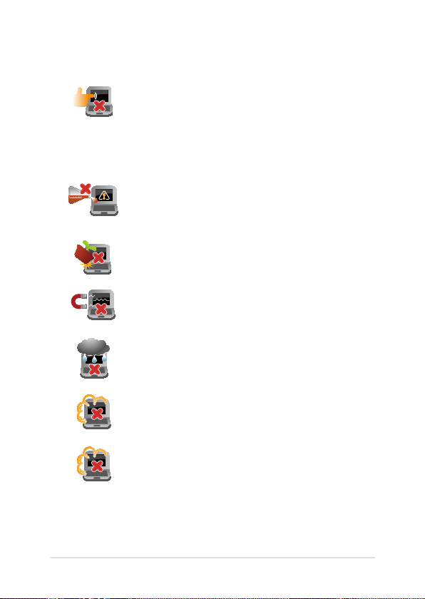
Disconnect the AC power and remove the battery
pack (if applicable) before cleaning your Notebook
PC. Use a clean cellulose sponge or chamois cloth
dampened with a solution of nonabrasive detergent
and a few drops of warm water. Remove any extra
moisture from your Notebook PC using a dry cloth.
Do not use strong solvents such as thinners,
benzene, or other chemicals on or near your
Notebook PC.
Do not place objects on top of your Notebook PC.
Do not expose your Notebook PC to strong
magnetic or electrical elds.
Do not use or expose your Notebook PC near
liquids, rain, or moisture.
Do not expose your Notebook PC to dusty
environments.
Do not use your Notebook PC near gas leaks.
Notebook PC E-Manual
9
Page 10
10
Notebook PC E-Manual
Proper disposal
Do not throw your Notebook PC in municipal waste.
This product has been designed to enable proper
reuse of parts and recycling. The symbol of the
crossed out wheeled bin indicates that the product
(electrical, electronic equipment and mercurycontaining button cell battery) should not be
placed in municipal waste. Check local regulations
for disposal of electronic products.
Do not throw the battery in municipal waste. The
symbol of the crossed out wheeled bin indicates
that the battery should not be placed in municipal
waste.
Page 11

Chapter 1: Hardware Setup
Notebook PC E-Manual
11
Page 12
12
Notebook PC E-Manual
Getting to know your Notebook PC
Top View
NOTE: The keyboard's layout may vary per region or country.
Page 13

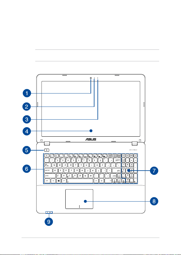
Camera
The built-in camera allows you to take pictures or record videos
using your Notebook PC.
Camera indicator
The camera indicator lights up when the built-in camera is in use.
Microphone
The built-in microphone can be used for video conferencing,
voice narrations, or simple audio recording.
Display panel
This high-denition display panel provides excellent viewing
features for photos, videos, and other multimedia les on your
Notebook PC.
Power button
Press the power button to turn your Notebook PC on or o. You
can also use the power button to put your Notebook PC to sleep
or hibernate mode and wake it up from sleep or hibernate mode.
In the event that your Notebook PC becomes unresponsive,
press and hold the power button for about four (4) seconds until
your Notebook PC shuts down.
Keyboard
The keyboard provides full-sized QWERTY keys with a
comfortable travel depth for typing. It also enables you to use
the function keys, allows quick access to Windows®, and controls
other multimedia functions.
NOTE: The keyboard layout diers by model or territory.
Notebook PC E-Manual
13
Page 14
14
Notebook PC E-Manual
Numeric keypad (on selected models)
The numeric keypad toggles between these two functions: for
numeric input and as pointer direction keys.
NOTE: For more details, refer to the Numeric keypad (on selected
models) section in this manual.
Touchpad
The touchpad allows the use of multi-gestures to navigate
onscreen, providing an intuitive user experience. It also simulates
the functions of a regular mouse.
NOTE: For more details, refer to the Gestures for the touchpad
section in this manual.
Status indicators
The status indicators help identify the current hardware status of
your Notebook PC.
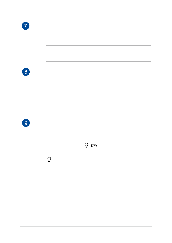
Power indicator
The power indicator lights up when the Notebook PC
is turned on and blinks slowly when the Notebook
PC is in sleep mode.
Page 15

Two-color battery charge indicator
The two-color LED provides a visual indication of the
battery’s charge status. Refer to the following table
for details:
Color Status
Solid Green The Notebook PC is plugged to
a power source and the battery
power is between 95% and
100%.
Solid Orange The Notebook PC is plugged
to a power source, charging its
battery, and the battery power
is less than 95%.
Blinking Orange The Notebook PC is running on
battery mode and the battery
power is less than 10%.
Lights o The Notebook PC is running on
Notebook PC E-Manual
battery mode and the battery
power is between 10% to 100%.
15
Page 16

16
Notebook PC E-Manual
Bottom
NOTE: The bottom side may vary in appearance depending on model.
WARNING! The bottom of the Notebook PC can get warm to hot while in
use or while charging the battery pack. When working on your Notebook
PC, do not place it on surfaces that can block the vents.
IMPORTANT! Battery time varies by usage and by the specications for
this Notebook PC. The battery pack cannot be disassembled.
Air vents
The air vents allow cool air to enter and warm air to exit the
Notebook PC.
WARNING! Ensure that paper, books, clothing, cables, or other
objects do not block any of the air vents or else overheating may
occur.
Page 17
Right Side
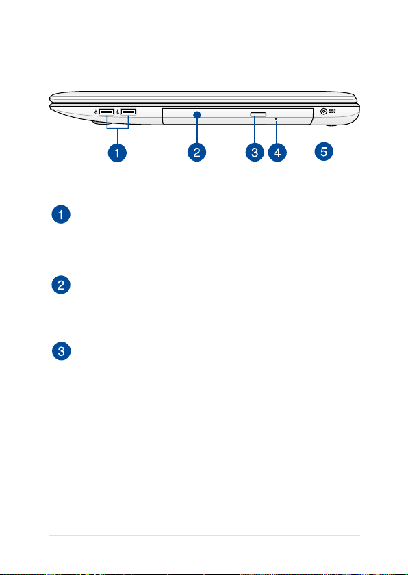
USB 2.0 ports (on selected models)
These USB (Universal Serial Bus) ports are compatible with USB
2.0 or USB 1.1 devices such as keyboards, pointing devices, ash
disk drives, external HDDs, speakers, cameras and printers.
Optical disc drive
Your Notebook PC’s optical drive may support several disc
formats such as CDs, DVDs, Blu-ray discs (on selected models)
recordable discs, or rewritable discs.
Optical disc drive electronic eject button
Press this button to eject the optical drive tray.
Notebook PC E-Manual
17
Page 18

18
Notebook PC E-Manual
Optical disc drive manual eject hole
The manual eject hole is used to eject the drive tray in case the
electronic eject button does not work.
WARNING! Use the manual eject hole only when the electronic
eject button does not work.
NOTE: For more details, refer to the Using the optical drive
section in this manual.
Power (DC) input port
Insert the bundled power adapter into this port to charge the
battery pack and supply power to your Notebook PC.
WARNING! The adapter may become warm to hot while in use.
Do not cover the adapter and keep it away from your body while
it is connected to a power source.
IMPORTANT! Use only the bundled power adapter to charge
the battery pack and supply power to your Notebook PC.
Page 19
Left Side
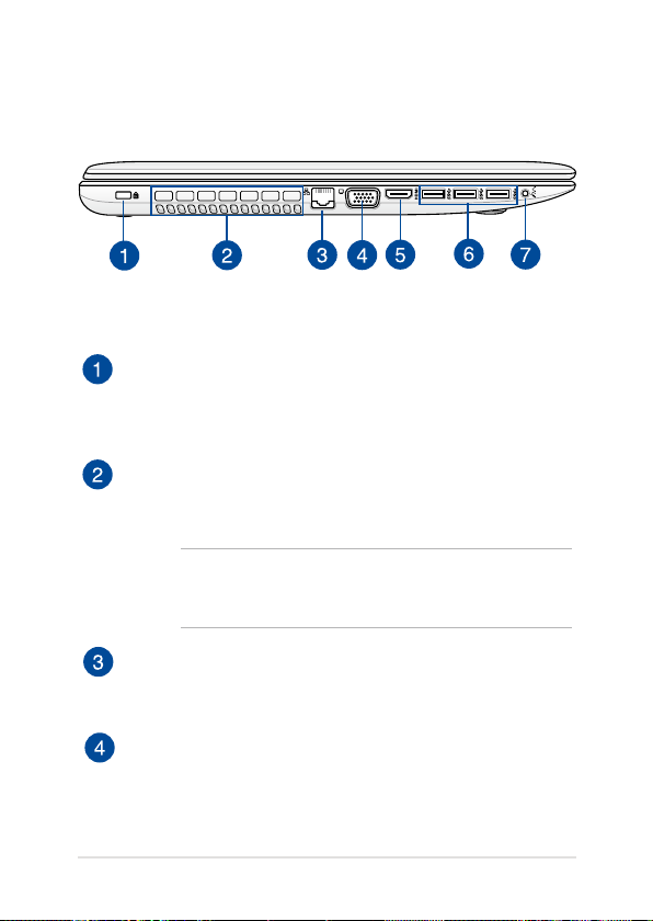
Kensington® security slot
The Kensington® security slot allows you to secure your
Notebook PC using Kensington® compatible Notebook PC
security products.
Air vents
The air vents allow cool air to enter and warm air to exit the
Notebook PC.
WARNING! Ensure that paper, books, clothing, cables, or other
objects do not block any of the air vents or else overheating may
occur.
LAN port
Insert the network cable into this port to connect to a local area
network (LAN).
VGA port
This port allows you to connect your Notebook PC to an
external display.
Notebook PC E-Manual
19
Page 20
20
Notebook PC E-Manual
HDMI port
This port is for a High-Denition Multimedia Interface (HDMI)
connector and is HDCP compliant for HD DVD, Blu-ray, and
other protected content playback.
USB 3.0 ports
The Universal Serial Bus 3.0 (USB 3.0) ports provide a transfer
rate of up to 5 Gbit/s and are backward compatible to USB 2.0.
Headphone output/microphone input combo jack port
This port allows you to connect your Notebook PC to amplied
speakers or headphones. You can also use this port to connect
your Notebook PC to an external microphone.
Front Side
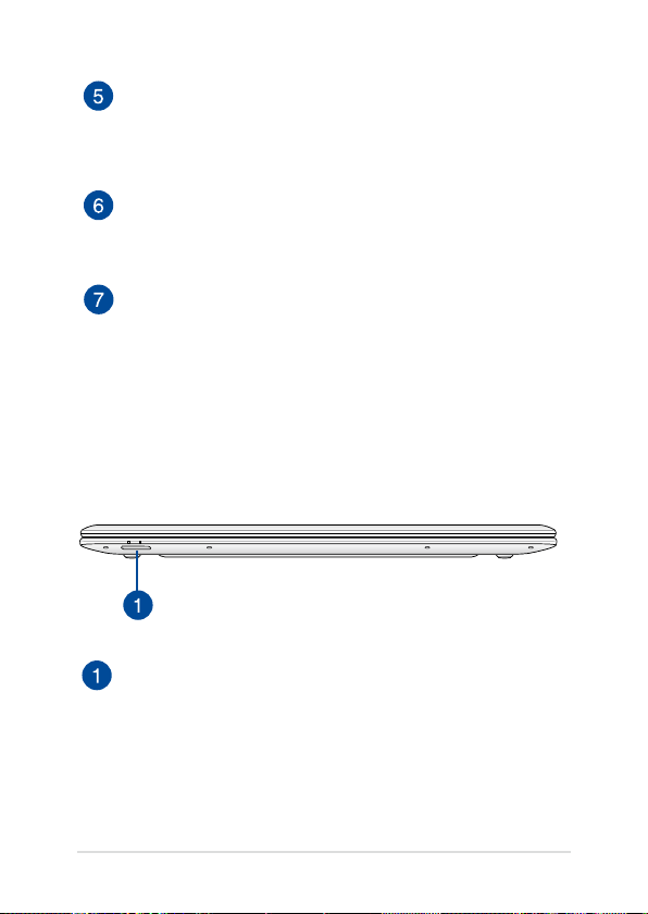
Memory card reader
This built-in memory card reader supports SD and SDHC card
formats.
Page 21

Chapter 2: Using your Notebook PC
Notebook PC E-Manual
21
Page 22
22
Notebook PC E-Manual
Getting started
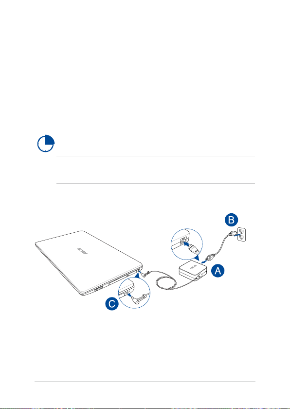
Charge your Notebook PC.
A. Connect the AC power cord to the AC/DC adapter.
B. Plug the AC power adapter into a 100V~240V power source.
C. Connect the DC power connector into your Notebook PC’s power
(DC) input.
Charge the Notebook PC for 3 hours before using it in
battery mode for the rst time.
NOTE: The power adapter may vary in appearance, depending on models
and your region.
Page 23

IMPORTANT!
• Locate the input/output rating label on your Notebook
PC and ensure that it matches the input/output rating
information on your power adapter. Some Notebook PC
models may have multiple rating output currents based on
the available SKU.
• Ensure that your Notebook PC is connected to the power
adapter before turning it on for the rst time. We strongly
recommend that you use a grounded wall socket while using
your Notebook PC on power adapter mode.
• The socket outlet must be easily accessible and near your
Notebook PC.
• To disconnect your Notebook PC from its main power supply,
unplug your Notebook PC from the power socket.
NOTE:
Power adapter information:
• Input voltage: 100-240Vac
• Input frequency: 50-60Hz
• Rating output current: 3.42A (65W)
• Rating output voltage: 19V
Notebook PC E-Manual
23
Page 24

24
Notebook PC E-Manual
WARNING!
Read the following precautions for your Notebook PC’s battery.
• Only ASUS-authorized technicians should remove the battery
inside the device.
• The battery used in this device may present a risk of re or
chemical burn if removed or disassembled.
• Follow the warning labels for your personal safety.
• Risk of explosion if battery is replaced by an incorrect type.
• Do not dispose of in re.
• Never attempt to short-circuit your Notebook PC’s battery.
• Never attempt to dissamble and reassemble the battery.
• Discontinue usage if leakage is found.
• The battery and its components must be recycled or disposed
of properly.
• Keep the battery and other small components away from
children.
Page 25
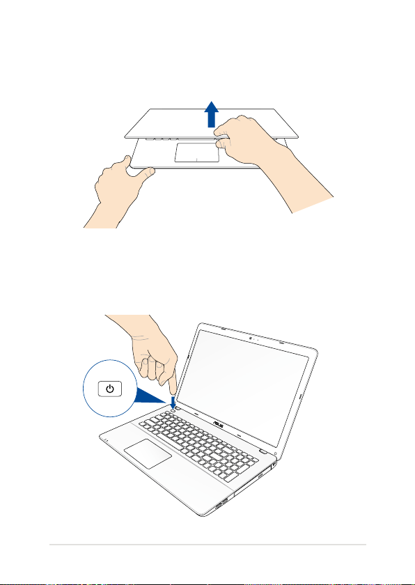
Lift to open the display panel.
Press the power button.
Notebook PC E-Manual
25
Page 26

26
Notebook PC E-Manual
Gestures for the touchpad
Gestures allow you to launch programs and access the settings of your
Notebook PC. Refer to the following illustrations when using hand
gestures on your touchpad.
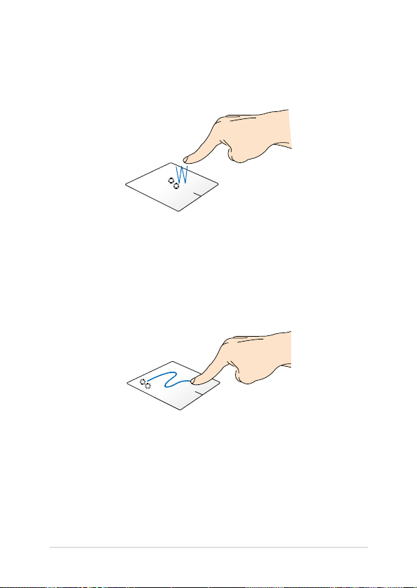
Moving the pointer
You can tap/click or click anywhere on the touchpad to activate its
pointer, then slide your nger on the touchpad to move the pointer
onscreen.
Slide horizontally
Slide vertically
Slide diagonally
Page 27
One-nger gestures
Tap/click/Double tap/click
• In the Start screen, tap/click an app to launch it.
• In Desktop mode, double-tap/click an application to launch it.
Drag and drop
Double-tap/click an item, then slide the same nger without lifting it
o the touchpad. To drop the item to its new location, lift your nger
from the touchpad.
Notebook PC E-Manual
27
Page 28
28
Notebook PC E-Manual
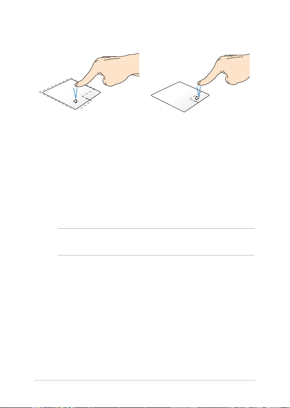
Left-click Right-click
• In the Start screen, click an
app to launch it.
• In Desktop mode, doubleclick an application to
launch it.
• In the Start screen, click an
app to select it and launch
the settings bar. You can also
press this button to launch
the All Apps bar.
• In Desktop mode, use this
button to open the rightclick menu.
NOTE: The areas inside the dotted line represent the locations of the left
mouse button and the right mouse button on the touchpad.
Page 29

Top edge swipe
• In the Start screen, swipe from the top edge to launch the All
Apps bar.
• In a running app, swipe from the top edge to view its menu.
Left edge swipe Right edge swipe
Swipe from the left edge to shue
your running apps.
Notebook PC E-Manual
Swipe the right edge to launch
the Charms bar.
29
Page 30
30
Notebook PC E-Manual
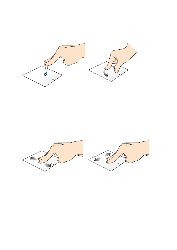
Two-nger gestures
Tap/click Rotate
Tap/click two ngers on the
touchpad to simulate the rightclick function.
To rotate an image, place two
ngers on the touchpad then
turn one nger clockwise or
counterclockwise while the other
stays still.
Two-nger scroll (up/down) Two-nger scroll (left/right)
Slide two ngers to scroll up or
down.
Slide two ngers to scroll left or
right.
Page 31
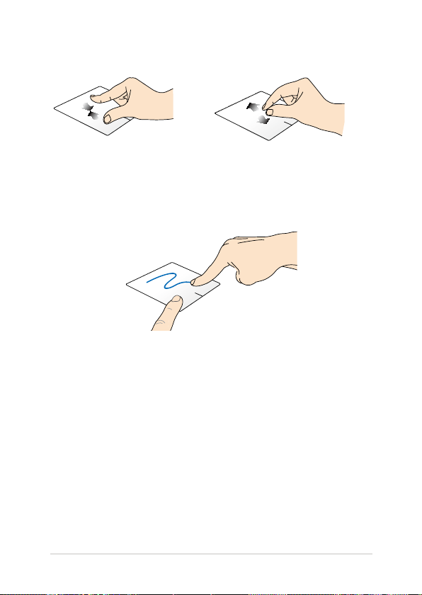
Zoom out Zoom in
Bring together your two ngers on
the touchpad.
Spread apart your two ngers on
the touchpad.
Drag and drop
Select an item then press and hold the left button. Using your other
nger, slide down the touchpad to drag and drop the item to a new
location.
Notebook PC E-Manual
31
Page 32
32
Notebook PC E-Manual
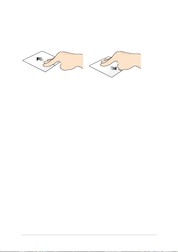
Three-nger gestures
Swipe up Swipe down
Swipe three ngers upward to
show all running applications.
Swipe three ngers downward to
show the Desktop mode.
Page 33
Using the keyboard
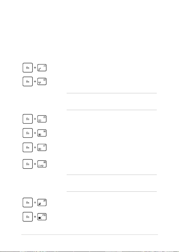
Function keys
The function keys on your Notebook PC’s keyboard can trigger the
following commands:
Puts the Notebook PC into Sleep mode
Turns Airplane mode on or o
NOTE: When enabled, the Airplane mode disables all
wireless connectivity.
Decreases display brightness
Increases display brightness
Turns the display panel o
Activates the second screen
NOTE: Ensure that the second display is connected to
your Notebook PC.
Enables or disables the touchpad
Turns the speaker on or o
Notebook PC E-Manual
33
Page 34
34
Notebook PC E-Manual
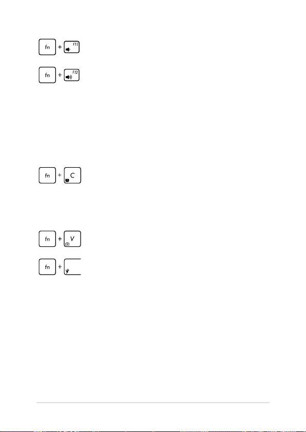
Turns the speaker volume down
Turns the speaker volume up
Function keys for ASUS Apps
Your Notebook PC also comes with a special set of function keys that
can be used to launch ASUS apps.
Toggles the ASUS Splendid Video Enhancement
Technology app to switch between these display
color enhancement modes: Gamma Correction, Vivid
Mode, Theater Mode, Soft Mode, My Prole, and
Normal.
Launches the ASUS LifeFrame app
Launches the ASUS Power4Gear Hybrid app
Page 35
Windows® 8.1 keys
There are two special Windows® keys on your Notebook PC’s keyboard
used as below:
Press this key to go back to the Start screen. If you are
already in the Start screen, press this key to go back to
the last app you opened.
Press this key to simulate the right-click functions.
Multimedia control keys (on selected models)
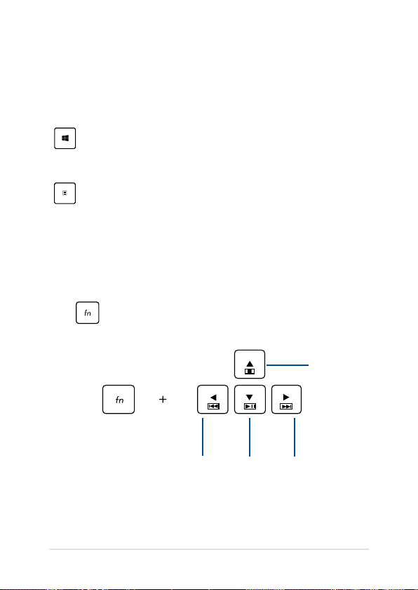
The multimedia control keys allow you to control multimedia les, such
as audios and videos, when played in your Notebook PC.
Press in combination with the arrow keys on your Notebook PC,
illustrated as below.
Stop
Notebook PC E-Manual
Skip to
previous
track or
rewind
Play or
pause
Skip to
next track
or fast
forward
35
Page 36
36
Notebook PC E-Manual
Numeric keypad (on selected models)
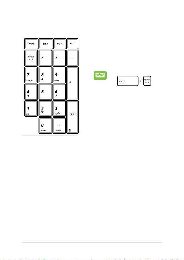
A numeric keypad is available on
selected Notebook PC models. You
can use this keypad for numeric
input or as pointer direction keys.
Press
toggle between using
the keypad as number
keys or as pointer
direction keys.
to
Page 37
Using the optical drive
NOTE: The actual location of the electronic eject button may vary
depending on your Notebook PC model.
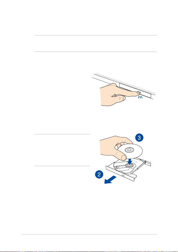
Inserting an optical disc
1. While the Notebook PC is
on, press the electronic eject
button to partially eject the
optical drive tray.
2. Gently pull out the drive tray.
IMPORTANT! Be careful not
to touch the optical drive lens.
Ensure that there are no objects
that may get jammed under the
drive tray.
3. Hold the disc by the edge,
with its printed side up, then
gently place it inside the hub.
Notebook PC E-Manual
37
Page 38
38
Notebook PC E-Manual
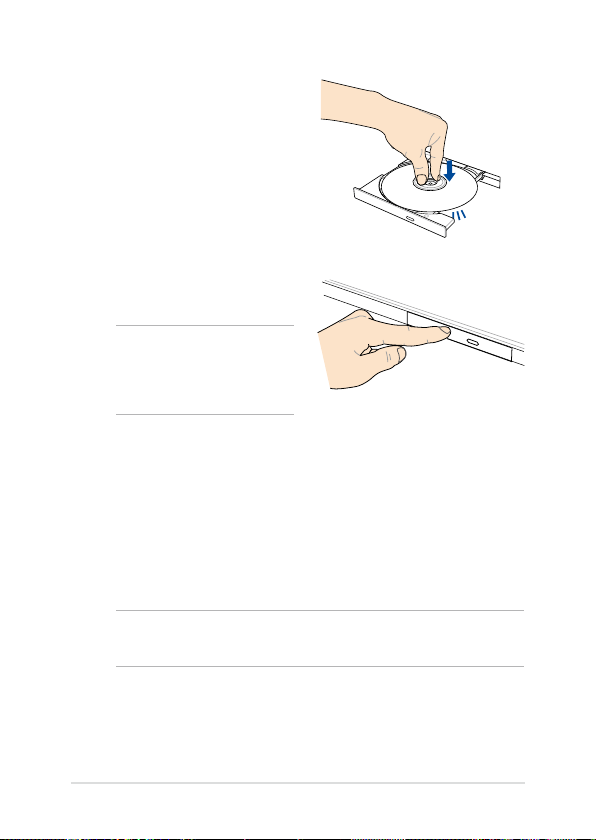
4. Push down the disc’s plastic
hub until it snaps onto the
optical drive hub.
5. Push the drive tray gently to
close the optical drive.
NOTE: While data is being
read, it is normal to hear some
spinning and vibrating in the
optical drive.
Manual eject hole
The manual eject hole is located on the optical drive door and is used to
eject the optical drive tray in case the electronic eject button does not
work.
To manually eject the optical drive tray, insert a straightened paper clip
into the manual eject hole until the drive tray opens.
WARNING! Use the manual eject hole only when the electronic eject
button does not work.
Page 39

Chapter 3: Working with Windows® 8.1
Notebook PC E-Manual
39
Page 40

40
Notebook PC E-Manual
Starting for the rst time
When you start your computer for the rst time, a series of screens
appear to guide you in conguring the basic settings of your Windows®
8.1 operating system.
To start your Notebook PC for the rst time:
1. Press the power button on your Notebook PC. Wait for a few
minutes until the setup screen appears.
2. From the setup screen, pick a language to use on your Notebook
PC.
3. Carefully read the License Terms. Tick I accept the terms for
using Windows then click Accept.
4. Follow the onscreen instructions to congure the following basic
items:
• Personalize
• Wireless
• Settings
• Sign in to your PC
5. After conguring the basic items, the Windows® 8.1 tutorial
appears. Watch this to learn more about Windows® 8.1
functionalities.
Windows® 8.1 lock screen
The Windows® 8.1 lock screen may appear when your Notebook PC
enters the Windows® 8.1 operating system. To proceed, tap/click on the
lock screen or press any key on your Notebook PC's keyboard.
Page 41
Windows® UI
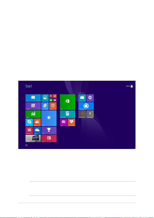
Windows® 8.1 comes with a tile-based user interface (UI) which allows
you to organize and easily access Windows® apps from the Start screen.
It also includes the following features that you can use while working
on your Notebook PC.
Start screen
The Start screen appears after successfully signing in to your user
account. It helps organize all the applications you need in just one
place.
Windows® Apps
These are apps pinned on the Start screen and displayed on tiled-format
for easy access.
NOTE: Some apps require signing in to your Microsoft account before
they are fully launched.
Notebook PC E-Manual
41
Page 42
42
Notebook PC E-Manual
Hotspots
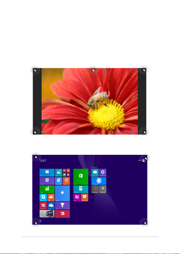
Onscreen hotspots allow you to launch programs and access the
settings of your Notebook PC. The functions in these hotspots can be
activated using the touchpad.
Hotspots on a running app
Hotspots on the Start screen
Page 43
Hotspot Action
upper left corner Hover your mouse pointer on the upper left
corner then tap/click on the recent app’s
thumbnail to revert back to that running app.
If you launched more than one app, slide
down to show all running apps.
lower left corner From a running app screen:
Hover your mouse pointer on the lower left
corner then tap/click to go back to the
Start screen.
NOTE: You can also press the Windows key
on your keyboard to go back to the
Start screen.
From the Start screen:
Hover your mouse pointer on the lower left
corner then tap/click to go back to that
app.
Notebook PC E-Manual
43
Page 44

44
Notebook PC E-Manual
Hotspot Action
top side Hover your mouse pointer on the top side
until it changes to a hand icon. Drag then
drop the app to a new location.
NOTE: This hotspot function only works on
a running app or when you want to use the
Snap feature. For more details, refer to the
Snap feature under Working with Windows®
apps.
upper or lower right
corner
Hover your mouse pointer on the upper or
lower right corner to launch the Charms bar.
Page 45
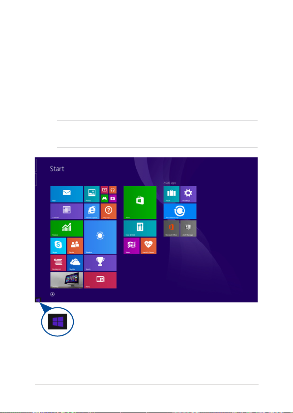
Start button
Windows® 8.1 features the Start button which allows you to switch
between the two most recent apps that you opened. The Start button
may be accessed from the Start screen, while on Desktop mode, and on
any app that is currently open onscreen.
Start button on the Start screen
NOTE: The actual color of your Start button varies depending on the
display settings you chose for your Start screen.
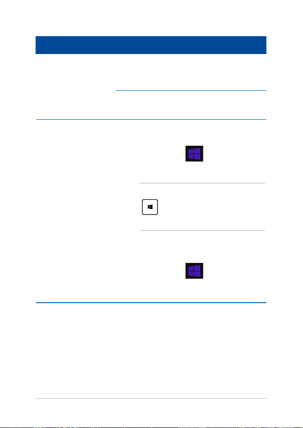
Hover your mouse pointer over the left corner of your Start
screen or any opened app to call out the Start button.
Notebook PC E-Manual
45
Page 46

46
Notebook PC E-Manual
Start button on Desktop mode
Context menu
The context menu appears as a box lled with quick access to some of
the programs inside Windows® 8.1 when you right-click on the Start
button.
The context menu also includes the following shut down options for
your Notebook PC: sign out, sleep, shut down, restart.
Page 47
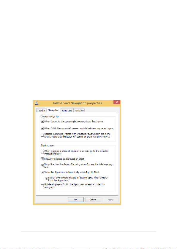
Customizing your Start screen
Windows® 8.1 also enables you to customize your Start screen,
allowing you to boot directly to the Desktop mode and customize the
arrangement of your apps onscreen.
To customize the settings of your Start screen:
1. Launch the Desktop.
2. Right-click anywhere on the taskbar, except on the Start button,
to launch the pop-up window.
3. Click Properties then select the Navigation tab to tick the
Navigation and Start screen options you want to use.
4. Tap/click Apply to save the new settings then exit.
Notebook PC E-Manual
47
Page 48
48
Notebook PC E-Manual
Working with Windows® apps
Use your Notebook PC’s touchpad or keyboard to launch, customize,
and close apps.
Launching apps
Position your mouse pointer over the app then left-click
or tap/click once to launch it.
Press until an app is selected then use the
arrow keys to browse through the apps. Press
to launch an app.
Customizing apps
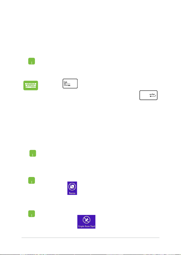
You can move, resize, unpin, or close apps from the Start screen using
the following steps:
Moving apps
Resizing apps
Double-tap/click on the app then drag and drop the app
to a new location.
Right-click on the app to activate its settings bar, then
tap/click and select an app tile size.
Unpinning apps
Right-click on the app to activate the Customize bar
then tap/click .
Page 49
Closing apps
1. Move your mouse pointer on the top side of the
2. Drag then drop the app to the bottom of the
From the running app’s screen, press .
launched app then wait for the pointer to change
to a hand icon.
screen to close it.
Notebook PC E-Manual
49
Page 50
50
Notebook PC E-Manual
Accessing the Apps screen
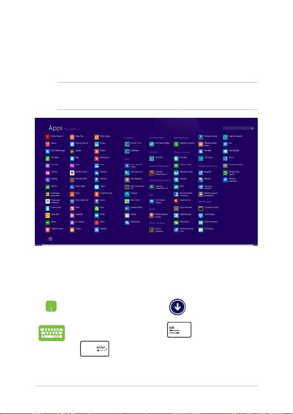
Aside from the apps already pinned on your Start screen, you can also
open other applications through the Apps screen.
NOTE: Actual apps shown onscreen may vary per model. The following
screenshot is for reference only.
Launching the Apps screen
Launch the Apps screen using your Notebook PC's touchpad or
keyboard.
On the Start screen, click the button.
From the Start screen, Press then press
.
Page 51

Pinning more apps on the Start screen
You can pin more apps on the Start screen using your touchpad.
1. Launch the All Apps screen
2. Right-click on the apps that you want to add on
the Start screen.
3. Tap/click on the icon to pin the selected
apps on the Start screen.
Notebook PC E-Manual
51
Page 52
52
Notebook PC E-Manual
Charms bar
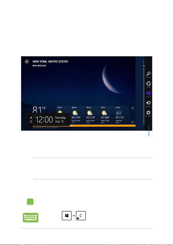
The Charms bar is a toolbar that can be triggered on the right side
of your screen. It consists of several tools that allow you to share
applications and provide quick access for customizing the settings of
your Notebook PC.
Charms bar
Launching the Charms bar
NOTE: When called out, the Charms bar initially appears as a set of
white icons. The image above shows how the Charms bar looks like once
activated.
Use your Notebook PC’s touchpad, or keyboard to launch the Charms
bar.
Move your mouse pointer on the upper or lower right
corner of the screen.
Press
Page 53
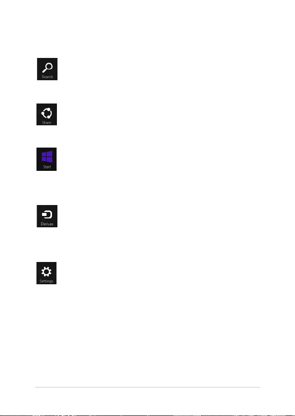
Inside the Charms bar
Search
This charm allows you to look for les, applications, or
programs in your Notebook PC.
Share
This charm allows you to share applications via social
networking sites or email.
Start
This charm reverts the display back to the Start screen.
From the Start screen, you can also use this to revert back
to a recently opened app.
Devices
This charm allows you to access and share les with
the devices attached to your Notebook PC such as an
external display or printer.
Settings
This charm allows you to access the PC settings of your
Notebook PC.
Notebook PC E-Manual
53
Page 54
54
Notebook PC E-Manual
Snap feature
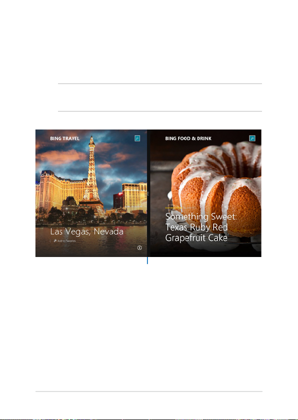
The Snap feature displays two apps side-by-side, allowing you to work
or switch between apps.
IMPORTANT! Ensure that your Notebook PC’s screen resolution is set to
1366 x 768 pixels or higher before using the Snap feature.
Snap bar
Page 55
Using Snap
Use your Notebook PC’s touchpad, or keyboard to activate and use
Snap.
1. Launch the app you wish to snap.
2. Hover the mouse point on the top side of your
screen.
3. Once the pointer changes to a hand icon, drag
then drop the app to the left or right side of the
display panel.
4. Launch another app.
1. Launch the app you wish to snap.
2. Press and the left or right arrow key to snap
the app to the left or right pane.
3. Launch another app. This app is automatically
placed in the empty pane.
Notebook PC E-Manual
55
Page 56
56
Notebook PC E-Manual
Other keyboard shortcuts
Using the keyboard, you can also use the following shortcuts to help
you launch applications and navigate Windows® 8.1.
\
Switches between the Start screen and the last
running app
Launches the desktop
Launches the This PC window on Desktop mode
Opens the File option from the Search charm
Opens the Share charm
Opens the Settings charm
Opens the Devices charm
Activates the Lock screen
Minimizes all currently active windows
Page 57
Launches the Project pane
Opens the Everywhere option from the
Search charm
Opens the Run window
Opens Ease of Access Center
Opens the Settings option under the Search
charm
Opens the context menu of the Start button
Launches the magnier icon and zooms in
your screen
Zooms out your screen
Opens the Narrator Settings
Notebook PC E-Manual
57
Page 58
58
Notebook PC E-Manual
Connecting to wireless networks
Wi-Fi
Access emails, surf the Internet, and share applications via social
networking sites using your Notebook PC’s Wi-Fi connection.
IMPORTANT! The Airplane mode disables this feature. Ensure that
Airplane mode is turned o before enabling the Wi-Fi connection of your
Notebook PC.
Enabling Wi-Fi
Activate Wi-Fi in your Notebook PC using the following steps on your
touch screen panel or touchpad.
1. Launch the Charms bar.
2. Tap/click and tap/click .
3. Select an access point from the list of available Wi-Fi
connections.
4. Tap/click Connect to start the network connection.
NOTE: You may be prompted to enter a security key to
activate the Wi-Fi connection.
5. If you want to enable sharing between your
Notebook PC and other wireless-enabled systems,
tap/click Yes. Tap/click No if you do not want to
enable the sharing function.
Page 59
Bluetooth
Use Bluetooth to facilitate wireless data transfers with other Bluetoothenabled devices.
IMPORTANT! The Airplane mode disables this feature. Ensure that
Airplane mode is turned o before enabling the Bluetooth connection of
your Notebook PC.
Pairing with other Bluetooth-enabled devices
You need to pair your Notebook PC with other Bluetooth-enabled
devices to enable data transfers. To do this, use your touchpad as
follows:
1. Launch the Charms bar.
2. Tap/click then tap/click Change PC Settings.
3. Under PC Settings, select Devices then tap/click Add
a Device to search for Bluetooth-enabled devices.
Notebook PC E-Manual
59
Page 60
60
Notebook PC E-Manual
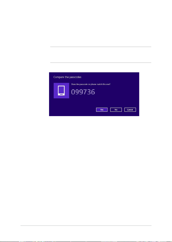
4. Select a device from the list. Compare the passcode
on your Notebook PC with the passcode sent to your
chosen device. If they are the same, tap/click Yes to
successfully pair your Notebook PC with the device.
NOTE: For some bluetooth-enabled devices, you may be
prompted to key in the passcode of your Notebook PC.
Page 61
Airplane mode
The Airplane mode disables wireless communication, allowing you to
use your Notebook PC safely while in-ight.
Turning Airplane mode on
1. Launch the Charms bar.
2. Tap/click and tap/click .
3. Move the slider to the right to turn the Airplane
mode on.
Press .
Turning Airplane mode o
1. Launch the Charms bar.
2. Tap/click and tap/click .
3. Move the slider to the left to turn the Airplane
mode o.
Press .
NOTE: Contact your airline provider to learn about related inight services
that can be used and restrictions that must be followed when using your
Notebook PC in-ight.
Notebook PC E-Manual
61
Page 62
62
Notebook PC E-Manual
Connecting to wired networks
You can also connect to wired networks, such as local area networks
and broadband Internet connection, using your Notebook PC’s LAN
port.
NOTE: Contact your Internet Service Provider (ISP) for details or
your network administrator for assistance in setting up your Internet
connection.
To congure your settings, refer to the following procedures.
IMPORTANT! Ensure that a network cable is connected between your
Notebook PC’s LAN port and a local area network before performing the
following actions.
Conguring a dynamic IP/PPPoE network
connection
1. LaunchLaunch Desktop.
2. From the Windows® taskbar, right-click the network
icon then tap/click Open Network and
Sharing Center.
3. In the Network and Sharing Center window, tap/
click Change adapter settings.
4. Right-click on your LAN then select Properties.
5. Tap/click Internet Protocol Version 4(TCP/IPv4)
then tap/click Properties.
Page 63
6. Tap/click Obtain an IP address automatically then
tap/click OK.
NOTE: Proceed to the next steps if you are using PPPoE connection.
7. Return to the Network and Sharing Center
window then tap/click Set up a new connection or
network.
8. Select Connect to the Internet then tap/click Next.
9. Tap/click Broadband (PPPoE).
10. Type your User name, Password, and Connection
name then tap/click Connect.
11. Tap/click Close to nish the conguration.
12. Tap/click on the taskbar then tap/click the
connection you just created.
13. Type your user name and password then tap/click
Connect to start connecting to the Internet.
Conguring a static IP network connection
1. Repeat steps 1 to 5 under Conguring a dynamic
IP/PPPoE network connection.
2 Tap/click Use the following IP address.
3. Type the IP address, Subnet mask and Default
gateway from your service provider.
4. If needed, you can also type the preferred DNS
server address and alternate DNS server address
then tap/click OK.
Notebook PC E-Manual
63
Page 64
64
Notebook PC E-Manual
Turning your Notebook PC off
You can turn o your Notebook PC by doing either of the following
procedures:
• Hover on the lower left corner of your screen to
launch the Start Button, then right-click on it. In
the context menu, select Shutdown or signout
> Shut down.
• Tap/click from the Charms bar then
tap/click > Shut down to do a normal
shutdown.
• From the log-in screen, tap/click > Shut
down.
• You can also shut down your Notebook PC using
Desktop mode. To do this, launch the desktop
then press alt + f4 to launch the Shut Down
window. Select Shut Down from the drop-down
list then select OK.
• If your Notebook PC is unresponsive, press
and hold the power button for at least four (4)
seconds until your Notebook PC turns o.
Page 65

Putting your Notebook PC to sleep
To put your Notebook PC on Sleep mode, press the power button once.
You can also put your Notebook PC to sleep mode
using Desktop mode. To do this, launch the desktop
then press alt + f4 to launch the Shut Down window.
Select Sleep from the drop-down list then select OK.
Notebook PC E-Manual
65
Page 66

66
Notebook PC E-Manual
Page 67

Chapter 4: Power-on Self Test (POST)
Notebook PC E-Manual
67
Page 68

68
Notebook PC E-Manual
The Power-on Self Test (POST)
The Power-on Self Test (POST ) is a series of software-controlled
diagnostic tests that run when you turn on or restart your Notebook PC.
The software that controls the POST is installed as a permanent part of
the Notebook PC’s architecture.
Using POST to access BIOS and Troubleshoot
During POST, you can access the BIOS settings or run troubleshooting
options using the function keys of your Notebook PC. You may refer to
the following information for more details.
BIOS
The Basic Input and Output System (BIOS) stores system hardware
settings that are needed for system startup in the Notebook PC.
The default BIOS settings apply to most conditions of your Notebook
PC. Do not change the default BIOS settings except in the following
circumstances:
• An error message appears onscreen during system bootup and
requests you to run the BIOS Setup.
• You have installed a new system component that requires further
BIOS settings or updates.
WARNING: Using inappropriate BIOS settings may result to system
instability or boot failure. We strongly recommend that you change the
BIOS settings only with the help of a trained service personnel.
Accessing BIOS
Restart your Notebook PC then press during POST.
Page 69
BIOS Settings
NOTE: The BIOS screens in this section are for reference only. The actual
screens may dier by model and territory.
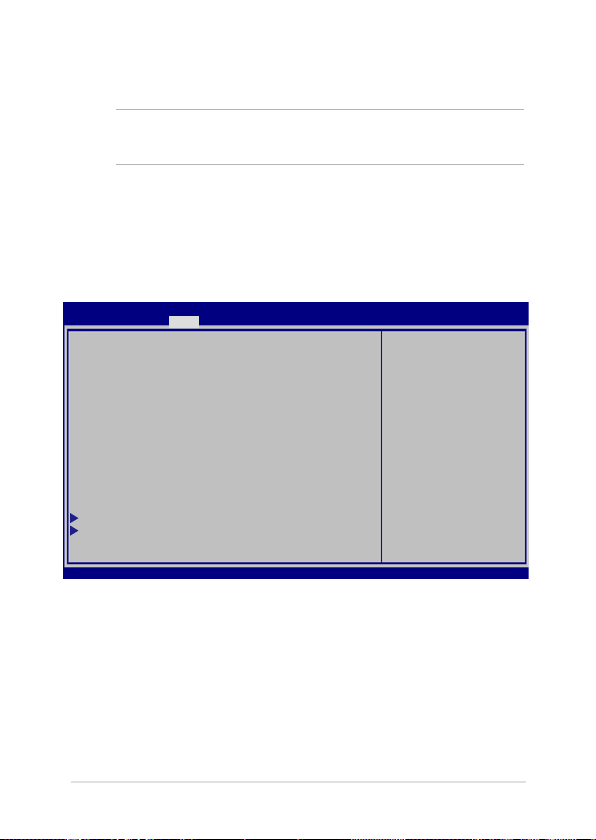
Boot
This menu allows you to set your boot option priorities. You may refer to
the following procedures when setting your boot priority.
1. On the Boot screen, select Boot Option #1.
Aptio Setup Utility - Copyright (C) 2012 American Megatrends, Inc.
Main Advanced Boot Security Save & Exit
Boot Conguration
Fast Boot [Enabled]
Launch CSM [Disabled]
Driver Option Priorities
Sets the system
boot order
Boot Option Priorities
Boot Option #1 [Windows Boot Manager]
Add New Boot Option
Delete Boot Option
Version 2.15.1226. Copyright (C) 2012 American Megatrends, Inc.
Notebook PC E-Manual
: Select Screen
→←
: Select Item
↑↓
Enter: Select
+/— : Change Opt.
F1 : General Help
F9 : Optimized Defaults
F10 : Save & Exit
ESC : Exit
69
Page 70
70
Notebook PC E-Manual
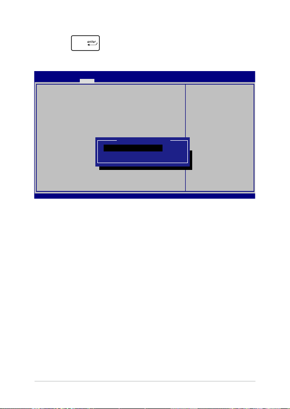
2. Press and select a device as the Boot Option #1.
Aptio Setup Utility - Copyright (C) 2012 American Megatrends, Inc.
Main Advanced Boot Security Save & Exit
Boot Conguration
Fast Boot [Enabled]
Launch CSM [Disabled]
Driver Option Priorities
Sets the system
boot order
Boot Option Priorities
Boot Option #1 [Windows Boot Manager]
Add New Boot Option
Delete Boot Option
Version 2.15.1226. Copyright (C) 2012 American Megatrends, Inc.
Boot Option #1
Windows Boot Manager
Disabled
: Select Screen
→←
: Select Item
↑↓
Enter: Select
+/— : Change Opt.
F1 : General Help
F9 : Optimized Defaults
F10 : Save & Exit
ESC : Exit
Page 71

Security
This menu allows you to set up the administrator and user password
of your Notebook PC. It also allows you to control the access to your
Notebook PC’s hard disk drive, input/output (I/O) interface, and USB
interface.
NOTE:
• If you install a User Password, you will be prompted to input
this before entering your Notebook PC's operating system.
• If you install an Administrator Password, you will be
prompted to input this before entering BIOS.
Aptio Setup Utility - Copyright (C) 2012 American Megatrends, Inc.
Main Advanced Boot Security Save & Exit
Password Description
If ONLY the Administrator’s password is set,
then this only limits access to Setup and is
only asked for when entering Setup. If ONLY
the user’s password is set, then this is a
power on password and must be entered to boot
or enter Setup. In Setup, the User will have
Administrator rights.
Administrator Password Status NOT INSTALLED
User Password Status NOT INSTALLED
Administrator Password
User Password
HDD Password Status : NOT INSTALLED
Set Master Password
Set User Password
I/O Interface Security
System Mode state User
Secure Boot state Enabled
Secure Boot Control [Enabled]
Key Management
Set Administrator
Password. The
password length
must be in the
following range:
Minimum length 3
Maximum length 20
: Select Screen
→←
: Select Item
↑↓
Enter: Select
+/— : Change Opt.
F1 : General Help
F9 : Optimized Defaults
F10 : Save & Exit
ESC : Exit
Version 2.15.1226. Copyright (C) 2012 American Megatrends, Inc.
Notebook PC E-Manual
71
Page 72
72
Notebook PC E-Manual
To set the password:
1. On the Security screen, select Administrator Password or User
Password.
2. Type in a password then press .
3. Re-type to conrm the password then press .
To clear the password:
1. On the Security screen, select Administrator Password or User
Password.
2. Type in the current password then press .
3. Leave the Create New Password eld blank then press
.
4. Select Yes in the conrmation box then press .
Page 73
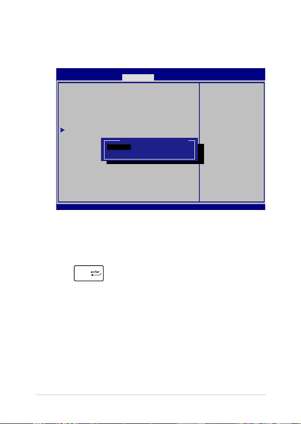
I/O Interface Security
In the Security menu, you can access I/O Interface Security to lock
or unlock some interface functions of your Notebook PC.
Aptio Setup Utility - Copyright (C) 2012 American Megatrends, Inc.
I/O Interface Security
LAN Network Interface [UnLock]
Wireless Network Interface [UnLock]
HD AUDIO Interface [UnLock]
USB Interface Security
Version 2.15.1226. Copyright (C) 2012 American Megatrends, Inc.
Security
LAN Network Interface
Lock
UnLock
If Locked, LAN
controller will
be disabled.
: Select Screen
→←
: Select Item
↑↓
Enter: Select
+/— : Change Opt.
F1 : General Help
F9 : Optimized
Defaults
F10 : Save & Exit
ESC : Exit
To lock an interface:
1. On the Security screen, select I/O Interface Security.
2. Select an interface you would like to lock then press
.
3. Select Lock.
Notebook PC E-Manual
73
Page 74
74
Notebook PC E-Manual
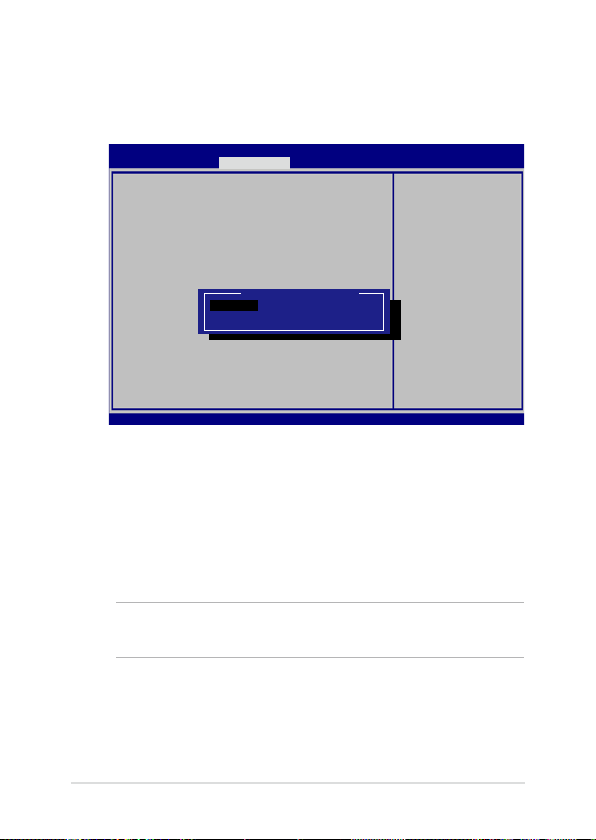
USB Interface Security
Through the I/O Interface Security menu, you can also access USB
Interface Security to lock or unlock ports and devices.
Aptio Setup Utility - Copyright (C) 2012 American Megatrends, Inc.
USB Interface Security
USB Interface [UnLock]
External Ports [UnLock]
CMOS Camera [UnLock]
Card Reader [UnLock]
Version 2.15.1226. Copyright (C) 2012 American Megatrends, Inc.
Security
Lock
UnLock
USB Interface
If Locked, all
USB device will
be disabled
: Select Screen
→←
: Select Item
↑↓
Enter: Select
+/— : Change Opt.
F1 : General Help
F9 : Optimized
Defaults
F10 : Save & Exit
ESC : Exit
To lock the USB interface:
1. On the Security screen, select I/O Interface Security > USB
Interface Security.
2. Select an interface that you would like to lock then select
Lock.
NOTE: Setting the USB Interface to Lock also locks and hides the
External Ports and other devices included under USB Interface Security.
Page 75
Set Master Password
In the Security menu, you can use Set Master Password to set up
a password-enabled access to your hard disk drive.
Aptio Setup Utility - Copyright (C) 2012 American Megatrends, Inc.
Main Advanced Boot Security Save & Exit
Aptio Setup Utility - Copyright (C) 2011 American Megatrends, Inc.
Password Description
If ONLY the Administrator’s password is
set,then this only limits access to Setup
and is only asked for when entering Setup.
If ONLY the user’s password is set, then
this is a power on password and must be
entered to boot or enter Setup. In Setup,
the User will have Administrator rights.
Administrator Password Status NOT INSTALLED
User Password Status NOT INSTALLED
Administrator Password
User Password
HDD Password Status : NOT INSTALLED
Set Master Password
Set User Password
I/O Interface Security
Version 2.15.1226. Copyright (C) 2012 American Megatrends, Inc.
Set HDD Master
Password.
***Advisable to
Power Cycle System
after Setting Hard
Disk Passwords***
: Select Screen
→←
: Select Item
↑↓
Enter: Select
+/— : Change Opt.
F1 : General Help
F9 : Optimized
Defaults
F10 : Save & Exit
ESC : Exit
To set the HDD password:
1. On the Security screen, select Set Master Password.
2. Type in a password then press .
3. Re-type to conrm the password then press .
4. Select Set User Password then repeat the previous steps to
set up the user password.
Notebook PC E-Manual
75
Page 76

76
Notebook PC E-Manual
Save & Exit
To keep your conguration settings, select Save Changes and Exit
before exiting the BIOS.
Aptio Setup Utility - Copyright (C) 2012 American Megatrends, Inc.
Main Advanced Boot Security Save & Exit
Save Changes and Exit
Discard Changes and Exit
Save Options
Save Changes
Discard Changes
Restore Defaults
Boot Override
Windows Boot Manager
Launch EFI Shell from lesystem device
Version 2.15.1226. Copyright (C) 2012 American Megatrends, Inc.
Exit system setup
after saving the
changes.
: Select Screen
→←
: Select Item
↑↓
Enter: Select
+/— : Change Opt.
F1 : General Help
F9 : Optimized Defaults
F10 : Save & Exit
ESC : Exit
Page 77
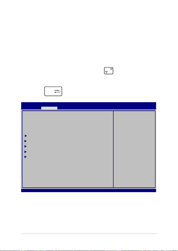
To update the BIOS:
1. Verify the Notebook PC’s exact model then download the latest
BIOS le for your model from the ASUS website.
2. Save a copy of the downloaded BIOS le to a ash disk drive.
3. Connect your ash disk drive to your Notebook PC.
4. Restart your Notebook PC then press during POST.
5. From the BIOS menu, Select Advanced > Start Easy Flash, then
press .
Aptio Setup Utility - Copyright (C) 2012 American Megatrends, Inc.
Aptio Setup Utility - Copyright (C) 2011 American Megatrends, Inc.
Main Advanced Boot Security Save & Exit
Start Easy Flash
Internal Pointing Device [Enabled]
Wake on Lid Open [Enabled]
Power Off Energy Saving [Enabled]
SATA Conguration
Graphics Conguration
Intel (R) Anti-Theft Technology Corporation
USB Conguration
Network Stack
Version 2.15.1226. Copyright (C) 2012 American Megatrends, Inc.
Press Enter to run
the utility to
select and update
BIOS.
: Select Screen
→←
: Select Item
↑↓
Enter: Select
+/— : Change Opt.
F1 : General Help
F9 : Optimized Defaults
F10 : Save & Exit
ESC : Exit
Notebook PC E-Manual
77
Page 78
78
Notebook PC E-Manual
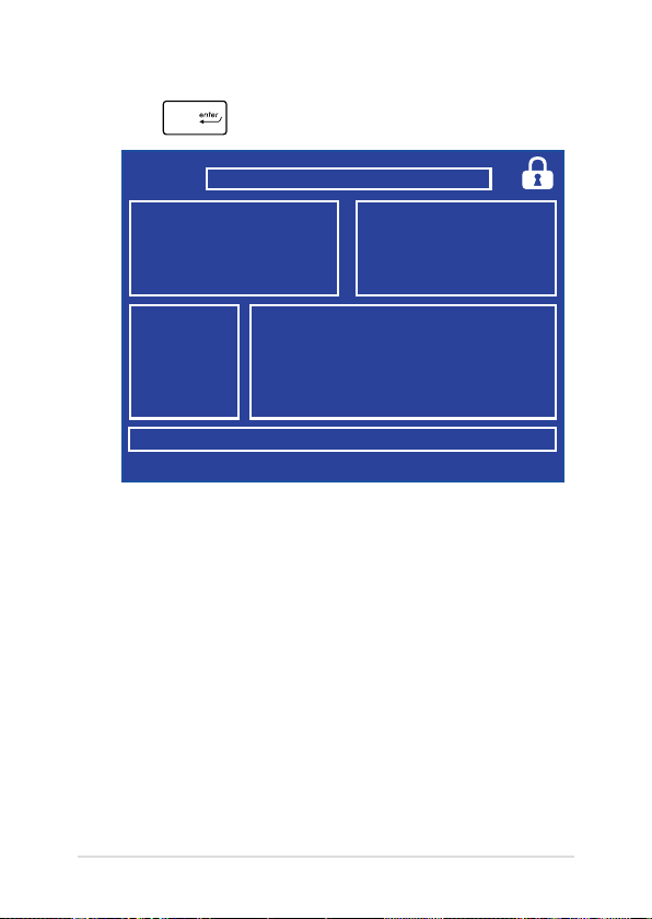
6. Locate your downloaded BIOS le in the ash disk drive then
press .
ASUSTek Easy Flash Utility
FLASH TYPE: MXIC 25L Series
Current BIOS
Platform: X751
Version: 101
Build Date: Oct 26 2012
Build Time: 11:51:05
FSO
FS1
FS2
FS3
FS4
[←→]: Switch [↑↓]: Choose [q]: Exit [Enter]: Enter/Execute
0 EFI
<DIR>
Platform: Unknown
Version: Unknown
Build Date: Unknown
Build Time: Unknown
New BIOS
7. After the BIOS update process, select Exit > Restore Defaults to
restore the system to its default settings.
Page 79
Troubleshoot
By pressing during POST, you can access Windows® 8.1
troubleshoot options which includes the following:
• Refresh your PC
• Reset your PC
• Advanced options
Refresh your PC
Use Refresh your PC if you want to refresh your system without losing
your current les and applications.
To access this during POST:
1. Restart your Notebook PC then press during
POST.
2. Wait for Windows® to load the Choose an option
screen then tap/click Troubleshoot.
3. Tap/click Refresh your PC.
4. In the Refresh your PC screen, read the bullet points
to learn more about using this option then tap/click
Next.
5. Tap/click the account you would like to refresh.
6. Type your account password then tap/click
Continue.
7. Tap/click Refresh.
Notebook PC E-Manual
IMPORTANT! Ensure that your Notebook PC is plugged in
to a power source before refreshing your system.
79
Page 80
80
Notebook PC E-Manual
Reset your PC
IMPORTANT! Back up all your data before performing this option.
Use Reset your PC to restore your Notebook PC to its default settings.
To access this during POST:
1. Restart your Notebook PC then press during
POST.
2. Wait for Windows® to load the Choose an option
screen then tap/click Troubleshoot.
3. Tap/click Reset your PC.
4. In the Reset your PC screen, read the bullet points
to learn more about using this option then tap/click
Next.
5. Tap/click your preferred reset option: Just remove
my les or Fully clean the drive.
6. Tap/click Reset.
IMPORTANT! Ensure that your Notebook PC is plugged in
to a power source before resetting your system.
Page 81
Advanced options
Use Advanced options to perform additional troubleshooting options
in your Notebook PC.
To access this during POST:
1. Restart your Notebook PC then press during
POST.
2. Wait for Windows® to load the Choose an option
screen then tap/click Troubleshoot.
3. Tap/click Advanced options.
4. In the Advanced options screen, select the
troubleshooting option you wish to perform.
5. Follow the succeeding steps to complete the
process.
Using System Image Recovery
Under Advanced options, you can use System Image Recovery to
recover your system using your Notebook PC’s original image le.
To access this during POST:
1. Restart your Notebook PC then press during
POST.
2. Wait for Windows® to load the Choose an option
screen then tap/click Troubleshoot.
3. Tap/click Advanced options.
Notebook PC E-Manual
81
Page 82

82
Notebook PC E-Manual
4. In the Advanced options screen, select System
Image Recovery.
5. Choose an account you would like to recover using
a system image le.
6. Type your account password then tap/click
Continue.
7. Select Use the latest available system image
(recommended), then tap/click Next. You can
also choose Select a system image if your system
image is in an external device or DVD.
8. Follow the succeeding steps to complete the
system image recovery procedure.
NOTE: We strongly recommend that you regularly backup
your system to prevent data loss in case your Notebook
PC stops working.
Page 83

Appendices
Notebook PC E-Manual
83
Page 84

84
Notebook PC E-Manual
DVD-ROM Drive Information (on selected models)
The DVD-ROM drive allows you to view and create your own CDs and DVDs. You
can purchase an optional DVD viewer software to view DVD titles.
Regional Playback Information
Playback of DVD movie titles involves decoding MPEG2 video, digital AC3 audio
and decryption of CSS protected content. CSS (sometimes called copy guard) is
the name given to the content protection scheme adopted by the motion picture
industry to satisfy a need to protect against unlawful content duplication.
Although the design rules imposed on CSS licensors are many, one rule that is
most relevant is playback restrictions on regionalized content. In order to facilitate
geographically staggered movie releases, DVD video titles are released for specic
geographic regions as dened in “Region Denitions” below. Copyright laws require
that all DVD movies be limited to a particular region (usually coded to the region at
which it is sold). While DVD movie content may be released for multiple regions, CSS
design rules require that any system capable of playing CSS encrypted content must
only be capable of playing one region.
IMPORTANT! The region setting may be changed up to ve times using the viewer
software, then it can only play DVD movies for the last region setting. Changing the
region code after that will require factory resetting which is not covered by warranty. If
resetting is desired, shipping and resetting costs will be at the expense of the user.
Page 85

Region Denitions
Region 1
Canada, US, US Territories
Region 2
Czech, Egypt, Finland, France, Germany, Gulf States, Hungary, Iceland, Iran,
Iraq, Ireland, Italy, Japan, Netherlands, Norway, Poland, Portugal, Saudi Arabia,
Scotland, South Africa, Spain, Sweden, Switzerland, Syria, Turkey, UK, Greece,
Former Yugoslav Republics, Slovakia
Region 3
Burma, Indonesia, South Korea, Malaysia, Philippines, Singapore, Taiwan, Thailand,
Vietnam
Region 4
Australia, Caribbean (Except US Territories), Central America, New Zealand, Pacic
Islands, South America
Region 5
CIS, India, Pakistan, Rest of Africa, Russia, North Korea
Region 6
China
Notebook PC E-Manual
85
Page 86

86
Notebook PC E-Manual
Blu-ray ROM Drive Information (on selected models)
The Blu-ray ROM Drive allows you to view high denition (HD) videos and other
disc le formats such as DVDs and CDs.
Region Denitions
Region A
North, Central and South American countries, and their territories; Taiwan, Hong
Kong, Macao, Japan, Korea (South and North), South East Asian countries and their
territories.
Region B
European, African, and South West Asian countries and their territories; Australia
and New Zealand.
Region C
Central, South Asian, Eastern European countries and their territories; China and
Mongolia.
NOTE: Refer to Blu-ray Disc website at www.blu-raydisc.com/en/Technical/FAQs/BlurayDiscforVideo.aspx for more details.
Internal Modem Compliancy
The Notebook PC with internal modem model complies with JATE (Japan), FCC
(US, Canada, Korea, Taiwan), and CTR21. The internal modem has been approved
in accordance with Council Decision 98/482/EC for pan-European single terminal
connection to the public switched telephone network (PSTN). However due
to dierences between the individual PSTNs provided in dierent countries,
the approval does not, of itself, give an unconditional assurance of successful
operation on every PSTN network termination point. In the event of problems you
should contact your equipment supplier in the rst instance.
Page 87

Overview
On 4th August 1998 the European Council Decision regarding the CTR 21 has
been published in the Ocial Journal of the EC. The CTR 21 applies to all non
voice terminal equipment with DTMF-dialling which is intended to be connected
to the analogue PSTN (Public Switched Telephone Network).
CTR 21 (Common Technical Regulation) for the attachment requirements for
connection to the analogue public switched telephone networks of terminal
equipment (excluding terminal equipment supporting the voice telephony
justied case service) in which network addressing, if provided, is by means of
dual tone multi-frequency signalling.
Network Compatibility Declaration
Statement to be made by the manufacturer to the Notied Body and the vendor:
“This declaration will indicate the networks with which the equipment is designed
to work and any notied networks with which the equipment may have interworking diculties.”
Statement to be made by the manufacturer to the user: “This declaration will
indicate the networks with which the equipment is designed to work and any
notied networks with which the equipment may have inter-working diculties.
The manufacturer shall also associate a statement to make it clear where network
compatibility is dependent on physical and software switch settings. It will also
advise the user to contact the vendor if it is desired to use the equipment on
another network.”
Up to now the Notied Body of CETECOM issued several pan-European approvals
using CTR 21. The results are Europe’s rst modems which do not require
regulatory approvals in each individual European country.
Non-Voice Equipment
Answering machines and loud-speaking telephones can be eligible as well as
modems, fax machines, auto-dialers and alarm systems. Equipment in which the
end-to-end quality of speech is controlled by regulations (e.g. handset telephones
and in some countries also cordless telephones) is excluded.
Notebook PC E-Manual
87
Page 88

88
Notebook PC E-Manual
This table shows the countries currently under the
CTR21 standard.
Country Applied More Testing
1
Austria
Belgium Yes No
Czech Republic No Not Applicable
1
Denmark
Finland Yes No
France Yes No
Germany Yes No
Greece Yes No
Hungary No Not Applicable
Iceland Yes No
Ireland Yes No
Italy Still Pending Still Pending
Israel No No
Lichtenstein Yes No
Luxemburg Yes No
The Netherlands
1
Norway Yes No
Poland No Not Applicable
Portugal No Not Applicable
Spain No Not Applicable
Sweden Yes No
Switzerland Yes No
United Kingdom Yes No
Yes No
Yes Yes
Yes Yes
Page 89

This information was copied from CETECOM and is supplied without liability. For
updates to this table, you may visit http://www.cetecom.de/technologies/ctr_21.
html
1 National requirements will apply only if the equipment may use pulse dialling
(manufacturers may state in the user guide that the equipment is only intended to
support DTMF signalling, which would make any additional testing superuous).
In The Netherlands additional testing is required for series connection and caller
ID facilities.
Federal Communications Commission Interference Statement
This device complies with FCC Rules Part 15. Operation is subject to the following
two conditions:
• This device may not cause harmful interference.
• This device must accept any interference received, including interference
that may cause undesired operation.
This equipment has been tested and found to comply with the limits for a class
B digital device, pursuant to Part 15 of the Federal Communications Commission
(FCC) rules. These limits are designed to provide reasonable protection against
harmful interference in a residential installation. This equipment generates, uses,
and can radiate radio frequency energy and, if not installed and used in accordance
with the instructions, may cause harmful interference to radio communications.
However, there is no guarantee that interference will not occur in a particular
installation. If this equipment does cause harmful interference to radio or television
reception, which can be determined by turning the equipment o and on, the user
is encouraged to try to correct the interference by one or more of the following
measures:
• Reorient or relocate the receiving antenna.
• Increase the separation between the equipment and receiver.
Notebook PC E-Manual
89
Page 90

90
Notebook PC E-Manual
• Connect the equipment into an outlet on a circuit dierent from that to
which the receiver is connected.
• Consult the dealer or an experienced radio/TV technician for help.
WARNING! The use of a shielded-type power cord is required in order to meet
FCC emission limits and to prevent interference to the nearby radio and television
reception. It is essential that only the supplied power cord be used. Use only shielded
cables to connect I/O devices to this equipment. You are cautioned that changes or
modications not expressly approved by the party responsible for compliance could
void your authority to operate the equipment.
(Reprinted from the Code of Federal Regulations #47, part 15.193, 1993.
Washington DC: Oce of the Federal Register, National Archives and Records
Administration, U.S. Government Printing Oce.)
FCC Radio Frequency (RF) Exposure Caution Statement
WARNING! Any changes or modications not expressly approved by the party
responsible for compliance could void the user’s authority to operate this equipment.
“The manufacture declares that this device is limited to Channels 1 through 11 in the
2.4GHz frequency by specied rmware controlled in the USA.”
This equipment complies with FCC radiation exposure limits set forth for an
uncontrolled environment. To maintain compliance with FCC RF exposure
compliance requirements, please avoid direct contact to the transmitting antenna
during transmitting. End users must follow the specic operating instructions for
satisfying RF exposure compliance.
Page 91
Declaration of Conformity (R&TTE directive 1999/5/EC)
The following items were completed and are considered relevant and sucient:
• Essential requirements as in [Article 3]
• Protection requirements for health and safety as in [Article 3.1a]
• Testing for electric safety according to [EN 60950]
• Protection requirements for electromagnetic compatibility in [Article 3.1b]
• Testing for electromagnetic compatibility in [EN 301 489-1] & [EN 301
489-17]
• Eective use of the radio spectrum as in [Article 3.2]
• Radio test suites according to [EN 300 328-2]
CE Marking
CE marking for devices without wireless LAN/Bluetooth
The shipped version of this device complies with the requirements of the EEC
directives 2004/108/EC “Electromagnetic compatibility” and 2006/95/EC “Low
voltage directive”.
CE marking for devices with wireless LAN/ Bluetooth
This equipment complies with the requirements of Directive 1999/5/EC of the
European Parliament and Commission from 9 March, 1999 governing Radio and
Telecommunications Equipment and mutual recognition of conformity.
Notebook PC E-Manual
91
Page 92

92
Notebook PC E-Manual
IC Radiation Exposure Statement for Canada
This equipment complies with IC radiation exposure limits set forth for an
uncontrolled environment. To maintain compliance with IC RF exposure
compliance requirements, please avoid direct contact to the transmitting antenna
during transmitting. End users must follow the specic operating instructions for
satisfying RF exposure compliance.
Operation is subject to the following two conditions:
• This device may not cause interference and
• This device must accept any interference, including interference that may
cause undesired operation of the device.
To prevent radio interference to the licensed service (i.e. co-channel Mobile
Satellite systems) this device is intended to be operated indoors and away from
windows to provide maximum shielding. Equipment (or its transmit antenna) that
is installed outdoors is subject to licensing.
This device complies with Industry Canada licence-exempt RSS standard(s).
Page 93

Déclaration d’Industrie Canada relative à l’ exposition aux ondes radio
Cet appareil est conforme aux limites d’exposition aux radiations d’Industrie
Canada dénies pour un environnement non-contrôlé. Pour maintenir la
conformité avec les exigences d’exposition RF d’IC, veuillez éviter tout contact
direct avec l’antenne pendant l’émission. Les utilisateurs naux doivent suivre
les instructions de fonctionnement spéciques pour satisfaire la conformité aux
expositions RF.
Son utilisation est sujette aux deux conditions suivantes :
• Cet appareil ne peut pas causer d’interférence, et
• Cet appareil doit accepter toute interférence, y compris les interférences
qui pourraient causer un fonctionnement non souhaité de l’appareil.
Pour éviter les interférences radio avec le service sous licence (c’est à-dire le
partage de canal avec les systèmes de téléphonie satellite), cet appareil est destiné
à être utilisé en intérieur et loin des fenêtres pour fournir un blindage maximal.
Tout appareil (ou son antenne d’émission) qui est installé en extérieur est sujet à
cette licence.
Le present appareil est conforme aux CNR d’Industrie Canada applicables aux
appareils radio exempts de licence.
Notebook PC E-Manual
93
Page 94

94
Notebook PC E-Manual
Wireless Operation Channel for Dierent
Domains
N. America 2.412-2.462 GHz Ch01 through CH11
Japan 2.412-2.484 GHz Ch01 through Ch14
Europe ETSI 2.412-2.472 GHz Ch01 through Ch13
France Restricted Wireless Frequency Bands
Some areas of France have a restricted frequency band. The worst case maximum
authorized power indoors are:
• 10mW for the entire 2.4 GHz band (2400 MHz–2483.5 MHz)
• 100mW for frequencies between 2446.5 MHz and 2483.5 MHz
NOTE: Channels 10 through 13 inclusive operate in the band 2446.6 MHz to 2483.5
MHz.
There are few possibilities for outdoor use: on private property or on the private
property of public persons, use is subject to a preliminary authorization procedure
by the Ministry of Defense, with maximum authorized power of 100mW in the
2446.5–2483.5 MHz band. Use outdoors on public property is not permitted.
In the departments listed below, for the entire 2.4 GHz band:
• Maximum authorized power indoors is 100mW
• Maximum authorized power outdoors is 10mW
Page 95

Departments in which the use of the 2400–2483.5 MHz band is permitted with an
EIRP of less than 100mW indoors and less than 10mW outdoors:
01 Ain 02 Aisne 03 Allier
05 Hautes Alpes 08 Ardennes 09 Ariège
11 Aude 12 Aveyron 16 Charente
24 Dordogne 25 Doubs 26 Drôme
32 Gers 36 Indre 37 Indre et Loire
41 Loir et Cher 45 Loiret 50 Manche
55 Meuse 58 Nièvre 59 Nord
60 Oise 61 Orne 63 Puy du Dôme
64 Pyrénées Atlantique 66 Pyrénées Orientales 67 Bas Rhin
68 Haut Rhin 70 Haute Saône 71 Saône et Loire
75 Paris 82 Tarn et Garonne 84 Vaucluse
88 Vosges 89 Yonne 90 Territoire de Belfort
94 Val de Marne
This requirement is likely to change over time, allowing you to use your wireless
LAN card in more areas within France. Please check with ART for the latest
information (www.arcep.fr)
NOTE: Your WLAN Card transmits less than 100mW, but more than 10mW.
Notebook PC E-Manual
95
Page 96

96
Notebook PC E-Manual
UL Safety Notices
Required for UL 1459 covering telecommunications (telephone) equipment
intended to be electrically connected to a telecommunication network that has an
operating voltage to ground that does not exceed 200V peak, 300V peak-to-peak,
and 105V rms, and installed or used in accordance with the National Electrical
Code (NFPA 70).
When using the Notebook PC modem, basic safety precautions should always be
followed to reduce the risk of re, electric shock, and injury to persons, including
the following:
• DO NOT use the Notebook PC near water, for example, near a bath tub,
wash bowl, kitchen sink or laundry tub, in a wet basement or near a
swimming pool.
• DO NOT use the Notebook PC during an electrical storm. There may be a
remote risk of electric shock from lightning.
• DO NOT use the Notebook PC in the vicinity of a gas leak.
Required for UL 1642 covering primary (nonrechargeable) and secondary
(rechargeable) lithium batteries for use as power sources in products. These
batteries contain metallic lithium, or a lithium alloy, or a lithium ion, and may
consist of a single electrochemical cell or two or more cells connected in series,
parallel, or both, that convert chemical energy into electrical energy by an
irreversible or reversible chemical reaction.
• Do not dispose the Notebook PC battery pack in a re, as they may
explode. Check with local codes for possible special disposal instructions
to reduce the risk of injury to persons due to re or explosion.
• Do not use power adapters or batteries from other devices to reduce the
risk of injury to persons due to re or explosion. Use only UL certied
power adapters or batteries supplied by the manufacturer or authorized
retailers.
Page 97

Power Safety Requirement
Products with electrical current ratings up to 6A and weighing more than 3Kg
must use approved power cords greater than or equal to: H05VV-F, 3G, 0.75mm2 or
H05VV-F, 2G, 0.75mm2.
TV Notices
Note to CATV System Installer—Cable distribution system should be grounded
(earthed) in accordance with ANSI/NFPA 70, the National Electrical Code (NEC),
in particular Section 820.93, Grounding of Outer Conductive Shield of a Coaxial
Cable – installation should include bonding the screen of the coaxial cable to the
earth at the building entrance.
REACH
Complying with the REACH (Registration, Evaluation, Authorization, and
Restriction of Chemicals) regulatory framework, we publish the chemical
substances in our products at ASUS REACH website at http://csr.asus.com/english/
REACH.htm.
Macrovision Corporation Product Notice
This product incorporates copyright protection technology that is protected by
method claims of certain U.S.A. patents and other intellectual property rights
owned by Macrovision Corporation and other rights owners. Use of this copyright
protection technology must be authorized by Macrovision Corporation, and
is intended for home and other limited viewing uses only
authorized by Macrovision Corporation
prohibited.
. Reverse engineering or disassembly is
unless otherwise
Prevention of Hearing Loss
To prevent possible hearing damage, do not listen at high volume
levels for long periods.
Notebook PC E-Manual
97
Page 98
98
Notebook PC E-Manual
Nordic Lithium Cautions (for lithium-ion batteries)
CAUTION! Danger of explosion if battery is incorrectly replaced. Replace only with
the same or equivalent type recommended by the manufacturer. Dispose of used
batteries according to the manufacturer’s instructions. (English)
ATTENZIONE! Rischio di esplosione della batteria se sostituita in modo errato.
Sostituire la batteria con un una di tipo uguale o equivalente consigliata dalla
fabbrica. Non disperdere le batterie nell’ambiente. (Italian)
VORSICHT! Explosionsgefahr bei unsachgemäßen Austausch der Batterie. Ersatz
nur durch denselben oder einem vom Hersteller empfohlenem ähnlichen Typ.
Entsorgung gebrauchter Batterien nach Angaben des Herstellers. (German)
ADVARSELI! Lithiumbatteri - Eksplosionsfare ved fejlagtig håndtering. Udskiftning
må kun ske med batteri af samme fabrikat og type. Levér det brugte batteri
tilbage til leverandøren. (Danish)
VARNING! Explosionsfara vid felaktigt batteribyte. Använd samma batterityp eller
en ekvivalent typ som rekommenderas av apparattillverkaren. Kassera använt
batteri enligt fabrikantens instruktion. (Swedish)
VAROITUS! Paristo voi räjähtää, jos se on virheellisesti asennettu. Vaihda paristo
ainoastaan laitevalmistajan sousittelemaan tyyppiin. Hävitä käytetty paristo
valmistagan ohjeiden mukaisesti. (Finnish)
ATTENTION! Il y a danger d’explosion s’il y a remplacement incorrect de la
batterie. Remplacer uniquement avec une batterie du mêre type ou d’un type
équivalent recommandé par le constructeur. Mettre au rebut les batteries usagées
conformément aux instructions du fabricant. (French)
ADVARSEL! Eksplosjonsfare ved feilaktig skifte av batteri. Benytt samme
batteritype eller en tilsvarende type anbefalt av apparatfabrikanten. Brukte
batterier kasseres i henhold til fabrikantens instruksjoner. (Norwegian)
(Japanese)
ВНИМАНИЕ! При замене аккумулятора на аккумулятор иного типа возможно
его возгорание. Утилизируйте аккумулятор в соответствии с инструкциями
производителя. (Russian)
Page 99

Optical Drive Safety Information
Laser Safety Information
CD-ROM Drive Safety Warning
CLASS 1 LASER PRODUCT
WARNING! To prevent exposure to the optical drive’s laser, do not attempt to
disassemble or repair the optical drive by yourself. For your safety, contact a
professional technician for assistance.
Service warning label
WARNING! INVISIBLE LASER RADIATION WHEN OPEN. DO NOT STARE INTO BEAM OR
VIEW DIRECTLY WITH OPTICAL INSTRUMENTS.
CDRH Regulations
The Center for Devices and Radiological Health (CDRH) of the U.S. Food and Drug
Administration implemented regulations for laser products on August 2, 1976.
These regulations apply to laser products manufactured from August 1, 1976.
Compliance is mandatory for products marketed in the United States.
WARNING! Use of controls or adjustments or performance of procedures other
than those specied herein or in the laser product installation guide may result in
hazardous radiation exposure.
Coating Notice
IMPORTANT! To provide electrical insulation and maintain electrical safety, a
coating is applied to insulate the device except on the areas where the I/O ports
are located.
Notebook PC E-Manual
99
Page 100
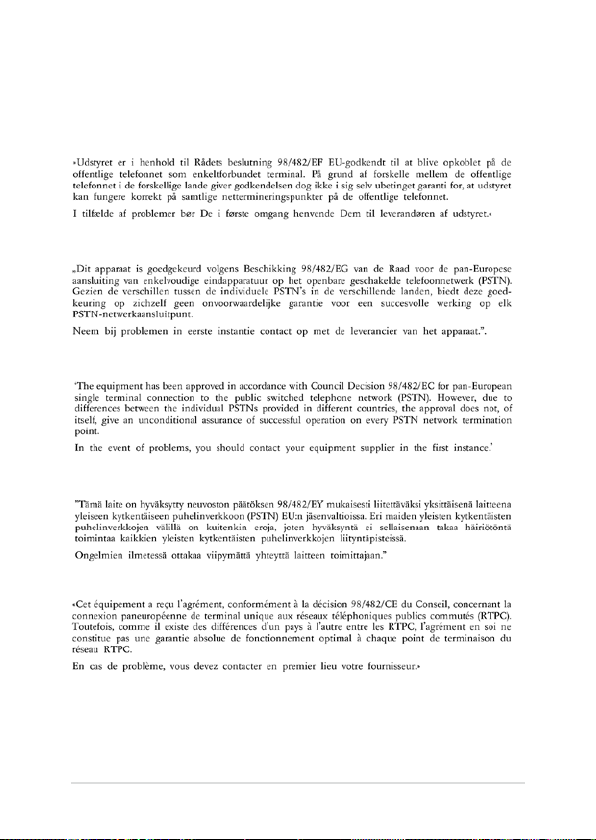
100
Notebook PC E-Manual
CTR 21 Approval (for Notebook PC with built-in Modem)
Danish
Dutch
English
Finnish
French
 Loading...