


ASUS X5BTP User Manual
Notebook PC
Hardware User’s Manual
E4017/ August 2008

2
Contents
Table of Contents
Table of Contents
1. Introducing the Notebook PC
About This User’s Manual ������������������������������������������������������������������������������������������6
Notes For This Manual ������������������������������������������������������������������������������������������� 6
Preparing your Notebook PC�������������������������������������������������������������������������������������� 9
2. Knowing the Parts
Top Side��������������������������������������������������������������������������������������������������������������������12
Bottom Side ��������������������������������������������������������������������������������������������������������������15
Left Side �������������������������������������������������������������������������������������������������������������������17
Right Side �����������������������������������������������������������������������������������������������������������������19
Rear Side������������������������������������������������������������������������������������������������������������������20
Front Side �����������������������������������������������������������������������������������������������������������������21
3. Getting Started
Power System ����������������������������������������������������������������������������������������������������������24
Using AC Power ��������������������������������������������������������������������������������������������������� 24
Using Battery Power �������������������������������������������������������������������������������������������� 25
Battery Care ��������������������������������������������������������������������������������������������������������� 26
Powering ON the Notebook PC ��������������������������������������������������������������������������� 27
The Power-On Self Test (POST) �������������������������������������������������������������������������� 27
Checking Battery Power �������������������������������������������������������������������������������������� 28
Charging the Battery Pack �����������������������������������������������������������������������������������28
Power Options ����������������������������������������������������������������������������������������������������� 29
Power Management Modes ���������������������������������������������������������������������������������30
Sleep and Hibernate �������������������������������������������������������������������������������������������� 30
Thermal Power Control ����������������������������������������������������������������������������������������30
Special Keyboard Functions �������������������������������������������������������������������������������������31
Colored Hot Keys ������������������������������������������������������������������������������������������������� 31
Microsoft Windows Keys �������������������������������������������������������������������������������������� 33
Extended Keyboard ��������������������������������������������������������������������������������������������� 33
Switches and Status Indicators ��������������������������������������������������������������������������������34
Switches���������������������������������������������������������������������������������������������������������������34
Switches and Status Indicators (cont�) ���������������������������������������������������������������������
35
Switches���������������������������������������������������������������������������������������������������������������35

3
Contents
Table of Contents (Cont.)
Status Indicators �������������������������������������������������������������������������������������������������� 36
Multimedia Control Keys (on selected models) ���������������������������������������������������38
4. Using the Notebook PC
Pointing Device���������������������������������������������������������������������������������������������������������40
Using the Touchpad ��������������������������������������������������������������������������������������������� 40
Touchpad Usage Illustrations �������������������������������������������������������������������������������41
Caring for the Touchpad ��������������������������������������������������������������������������������������� 42
Automatic Touchpad Disabling (Synaptics) ���������������������������������������������������������� 42
Storage Devices ������������������������������������������������������������������������������������������������������� 43
Expansion Card ��������������������������������������������������������������������������������������������������� 43
Optical Drive �������������������������������������������������������������������������������������������������������� 45
Flash Memory Card Reader ��������������������������������������������������������������������������������47
Hard Disk Drive ���������������������������������������������������������������������������������������������������� 48
Memory (RAM)�����������������������������������������������������������������������������������������������������50
Connections��������������������������������������������������������������������������������������������������������������51
Network Connection ��������������������������������������������������������������������������������������������51
Wireless LAN Connection (on selected models) �������������������������������������������������52
Windows Wireless Network Connection �������������������������������������������������������������� 53
Bluetooth Wireless Connection (on selected models) ����������������������������������������� 54
Antenna Connections (on selected models) �������������������������������������������������������� 55
Trusted Platform Module (TPM) (on selected models) ���������������������������������������������56
3G Watcher (on selected models and in selected territories) ����������������������������������� 59
Installing a Mobile SIM card ��������������������������������������������������������������������������������� 59
Using 3G Watcher software ���������������������������������������������������������������������������������59
Appendix
Optional Accessories ���������������������������������������������������������������������������������������������� A-2
Optional Connections ���������������������������������������������������������������������������������������� A-3
Bluetooth Mouse Setup (optional) ��������������������������������������������������������������������� A-4
Operating System and Software����������������������������������������������������������������������������� A-6
System BIOS Settings ��������������������������������������������������������������������������������������� A-7
Common Problems and Solutions ��������������������������������������������������������������������� A-9
Windows Vista Software Recovery ������������������������������������������������������������������ A-15
Glossary ��������������������������������������������������������������������������������������������������������������� A-17
Declarations and Safety Statements �������������������������������������������������������������������� A-21
Notebook PC Information ������������������������������������������������������������������������������������� A-34

4
Contents

5
1. Introducing the Notebook PC
About This User’s Manual
Notes For This Manual
Safety Precautions
Preparing your Notebook PC
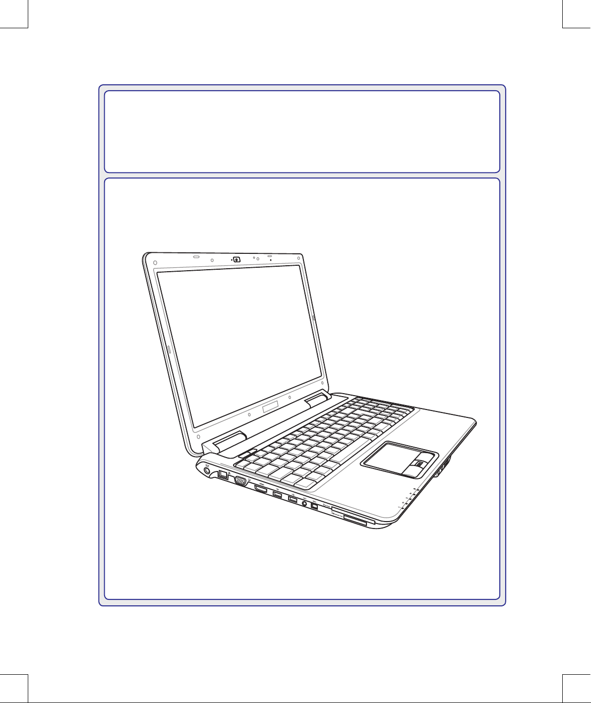
Photos and icons in this manual are used for artistic purposes only and do not
show what is actually used in the product itself.
There may be differences between your Notebook PC and the drawings shown in
this manual. Please accept your Notebook PC as being correct.

6
1 Introducing the Notebook PC
About This User’s Manual
You are reading the Notebook PC User’s Manual. This User’s Manual provides
information on the various components in the Notebook PC and how to use them. The
following are major sections of this User’s Manuals:
1. Introducing the Notebook PC
Introduces you to the Notebook PC and this User’s Manual.
2. Knowing the Parts
Gives you information on the Notebook PC’s components.
3. Getting Started
Gives you information on getting started with the Notebook PC.
4. Using the Notebook PC
Gives you information on using the Notebook PC’s components.
5. Appendix
Introduces you to optional accessories and gives additional information.
Notes For This Manual
A few notes and warnings in bold are used throughout this guide that you should be aware of in order
to complete certain tasks safely and completely. These notes have different degrees of importance as
described below:
NOTE: Tips and information for special situations.
TIP: Tips and useful information for completing tasks.
IMPORTANT! Vital information that must be followed to prevent damage to data,
components, or persons.
WARNING! Important information that must be followed for safe operation.
Text enclosed in < > or [ ] represents a key on the keyboard; do not actually type the
< > or [ ] and the enclosed letters.
< >
[ ]
7
Introducing the Notebook PC 1
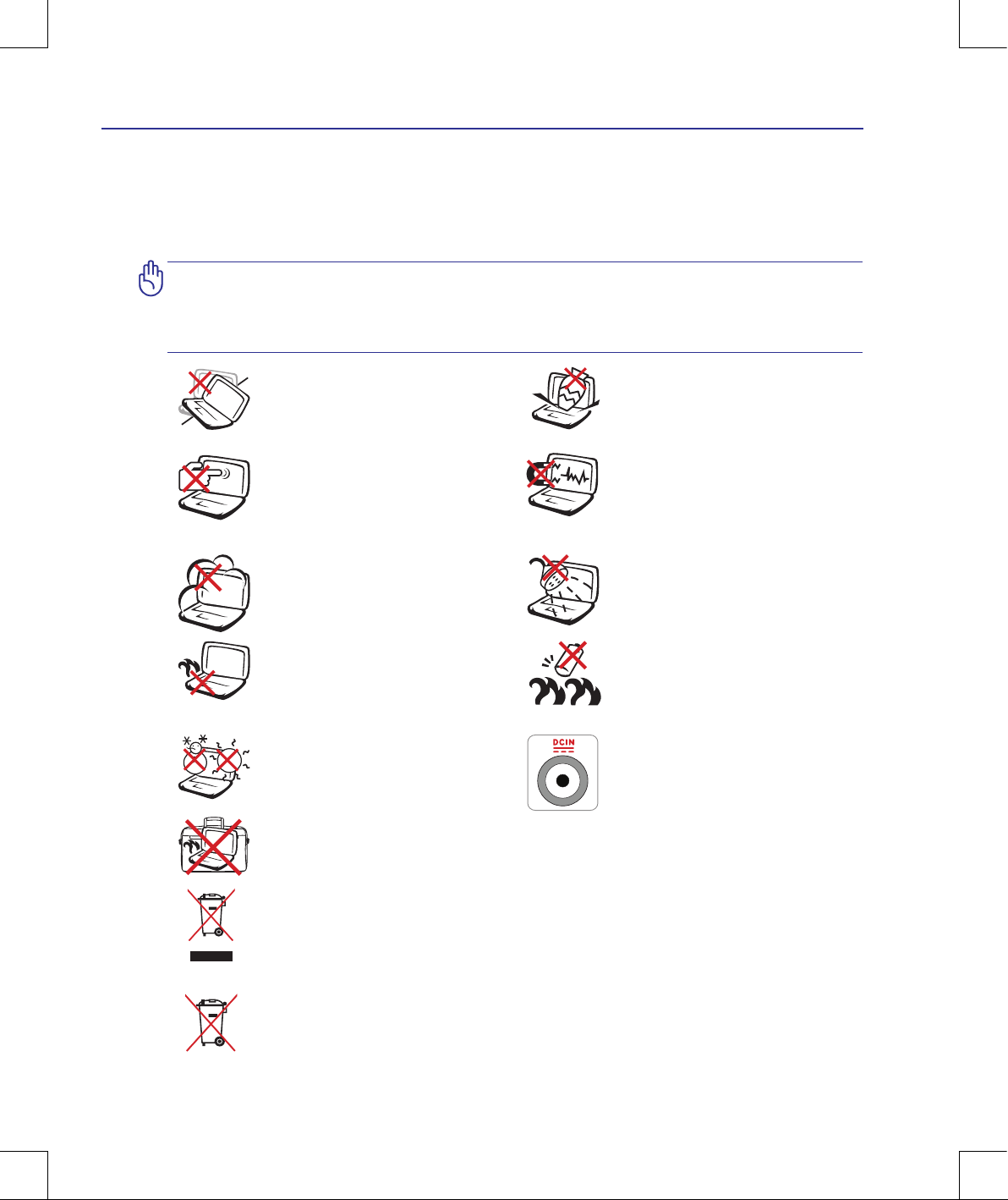
Safety Precautions
The following safety precautions will increase the life of the Notebook PC. Follow all precautions and
instructions. Except as described in this manual, refer all servicing to qualied personnel. Do not use
damaged power cords, accessories, or other peripherals. Do not use strong solvents such as thinners,
benzene, or other chemicals on or near the surface.
IMPORTANT! Disconnect the AC power and remove the battery pack(s) before
cleaning. Wipe the Notebook PC using a clean cellulose sponge or chamois cloth
dampened with a solution of nonabrasive detergent and a few drops of warm water
and remove any extra moisture with a dry cloth.
DO NOT
expose to or use near liquids,
rain, or moisture. DO NOT use the
modem during an electrical storm.
DO NOT expose to dirty or dusty environments. DO NOT operate during
a gas leak.
SAFE TEMP:
This Notebook PC
should only be used in environments
with ambient temperatures between
5°C (41°F) and 35°C (95°F)
Battery safety warning:
DO NOT
throw the battery in re.
DO NOT short circuit the contacts.
DO NOT disassemble the battery.
DO NOT
expose to strong magnetic
or electrical elds.
DO NOT place on uneven or unstable
work surfaces. Seek servicing if the
casing has been damaged.
DO NOT place or drop objects on
top and do not shove any foreign
objects into the Notebook PC.
DO NOT press or touch the display
panel. Do not place together with
small items that may scratch or enter
the Notebook PC.
DO NOT
leave the Notebook PC on
your lap or any part of the body in
order to prevent discomfort or injury
from heat exposure.
DO NOT throw the Notebook PC in municipal waste. This product has been designed
to enable proper reuse of parts and recycling. The symbol of the crossed out wheeled
bin indicates that the product (electrical, electronic equipment and mercury-containing
button cell battery) should not be placed in municipal waste. Check local regulations for
disposal of electronic products.
DO NOT carry or cover a Notebook PC that is powered ON with any materials that will
reduce air circulation such as a carrying bag.
INPUT RATING: Refer to the rating
label on the bottom of the Notebook
PC and be sure that your power adapter
complies with the rating.
DO NOT throw the battery in municipal waste. The symbol of the crossed out wheeled
bin indicates that the battery should not be placed in municipal waste.
8
1 Introducing the Notebook PC
CAUTION! There are three main types of airport security devices: X-ray machines
(used on items placed on conveyor belts), magnetic detectors (used on people
walking through security checks), and magnetic wands (hand-held devices used on
people or individual items). You can send your Notebook PC and diskettes through
airport X-ray machines. However, it is recommended that you do not send your
Notebook PC or diskettes through airport magnetic detectors or expose them to
magnetic wands.
Charge Your Batteries
If you intend to use battery power, be sure to fully charge your battery pack and any optional battery
packs before going on long trips. Remember that the power adapter charges the battery pack as long as
it is plugged into the computer and an AC power source. Be aware that it takes much longer to charge
the battery pack when the Notebook PC is in use.
Airplane Precautions
Contact your airline if you want to use the Notebook PC on the airplane. Most airlines will have
restrictions for using electronic devices. Most airlines will allow electronic use only between and not
during takeoffs and landings.
Transportation Precautions
To prepare the Notebook PC for transport, you should turn it OFF and disconnect all external peripherals to prevent damage to the connectors. The hard disk drive’s head retracts when the power
is turned OFF to prevent scratching of the hard disk surface during transport. Therefore, you should
not transport the Notebook PC while the power is still ON. Close the display panel and check that it is
latched securely in the closed position to protect the keyboard and display panel.
CAUTION! The Notebook PC’s surface is easily dulled if not properly cared for. Be
careful not to rub or scrape the Notebook PC surfaces.
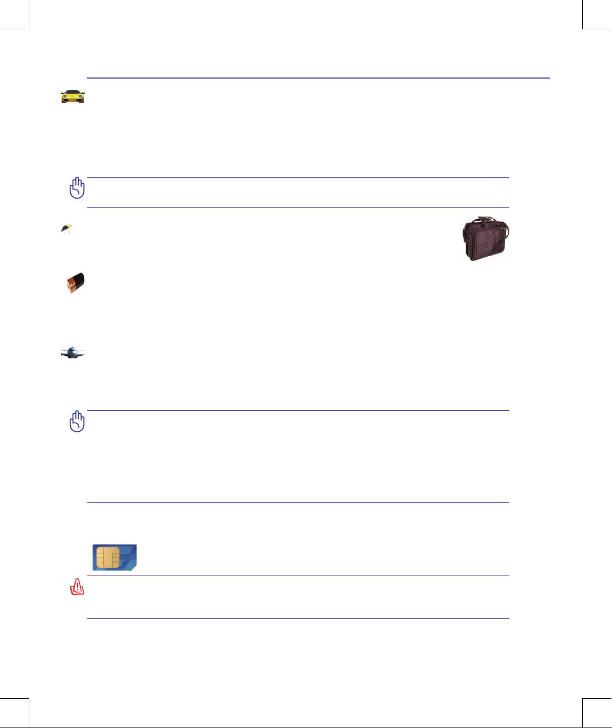
Cover Your Notebook PC
Purchase a carrying bag to protect the Notebook PC from dirt, water, shock, and scratches.
(1)
(See end of Section 4 for definition)
Models with 3G
(1)
: Produces radio wave emissions that may cause electrical interferences
and must be used in places that do not prohibit such devices. Take precautions while using.
WARNING! The 3G function needs to be switched OFF in areas with potentially explosive
atmospheres such as petrol (gas) stations, chemical storage depots, and blasting operations.
9
Introducing the Notebook PC 1
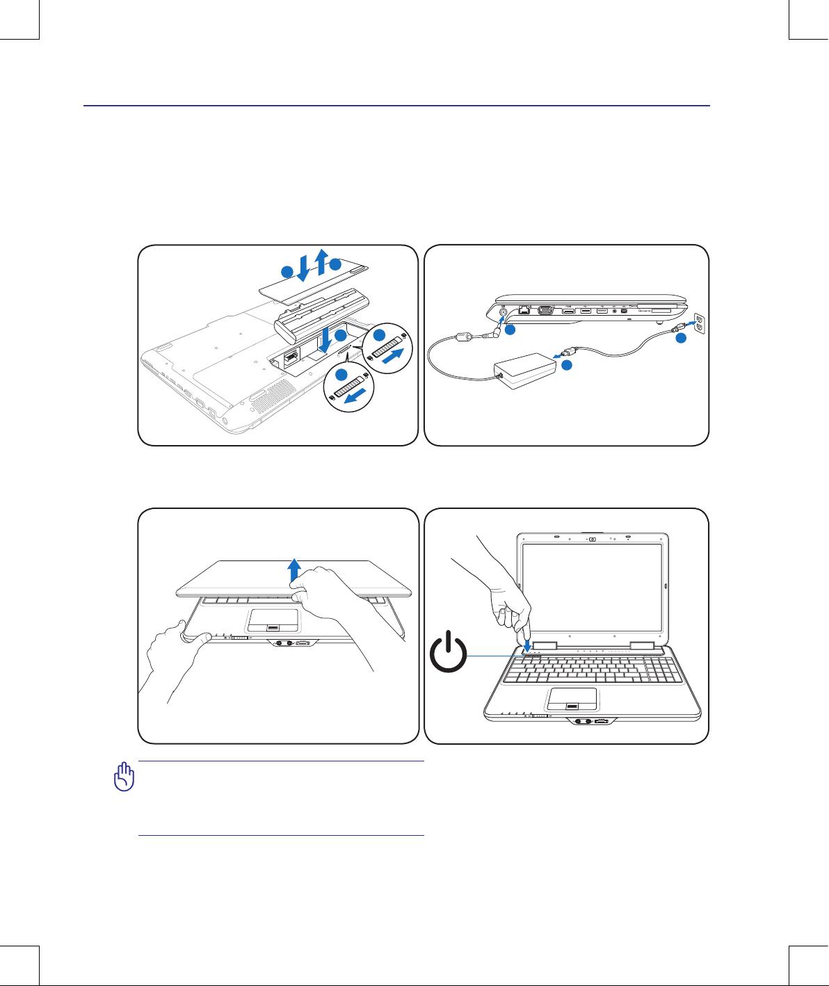
Preparing your Notebook PC
These are only quick instructions for using your Notebook PC. Read the later pages for detailed information on using your Notebook PC.
1. Install the battery pack
2. Connect the AC Power Adapter
IMPORTANT! When opening, DO NOT
force the display panel down to the table
or else the hinges may break! Never lift
the Notebook PC by the display panel!
1
3
2
5
4
3. Open the Display Panel 4. Turn ON the Notebook PC
The power switch turns ON and OFF the Notebook PC or putting the Notebook PC into sleep
or hibernation modes. Actual behavior of the
power switch can be customized in Windows
Control Panel > Power Options > System Set-
tings.
1
2
3

10
1 Introducing the Notebook PC

11
2. Knowing the Parts
Basic sides of the Notebook PC
Photos and icons in this manual are used for artistic purposes only and do not
show what is actually used in the product itself.
There may be differences between your Notebook PC and the drawings shown in
this manual. Please accept your Notebook PC as being correct.
12
2 Knowing the Parts
5
4
7
8
9
6
1
2
3
12
13
11
10
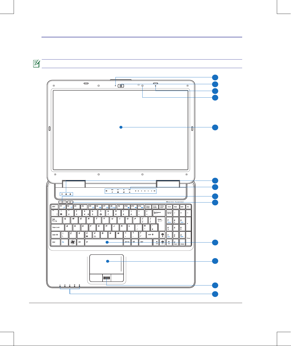
Top Side
Refer to the illustration below to identify the components on this side of the Notebook PC.
The keyboard differs for each territory.
13
Knowing the Parts 2
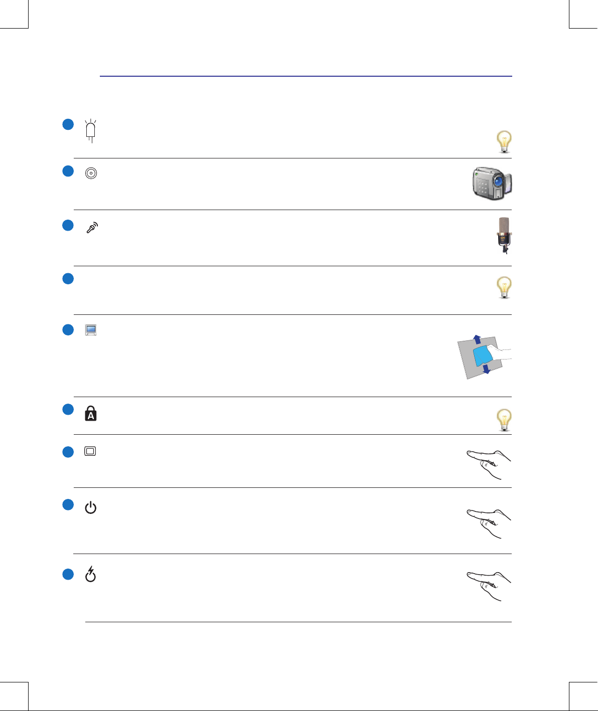
Camera Indicator
The camera indicator shows when the built-in camera is in use. The camera may be auto-activated
by supported software.
Display Panel
The display panel functions the same as a desktop monitor. The Notebook PC uses an
active matrix TFT LCD, which provides excellent viewing like that of desktop monitors.
Unlike desktop monitors, the LCD panel does not produce any radiation or ickering, so it
is easier on the eyes. Use a soft cloth without chemical liquids (use plain water if necessary)
to clean the display panel.
Status Indicators (top)
Status indicators represent various hardware/software conditions. See indicator details in section 3.
Dual Mode Instant Keys (touch sensitive)
Dual mode instant keys provide two sets of instant keys for you to launch frequently used
applications with one touch of a button. Details are described in section 3.
Camera (on selected models)
The built-in camera allows picture taking or video recording. Can be used with video conferencing and other interactive applications.
2
3
4
5
6
7
Microphone (Built-in)
The built-in mono microphone can be used for video conferencing, voice narrations, or simple
audio recordings.
1
8
Power Switch
The power switch turns ON and OFF the Notebook PC or putting the Notebook PC into
sleep or hibernation modes. Actual behavior of the power switch can be customized in
Windows Control Panel “Power Options.”
Light Sensor (on selected models)
The light sensor measures the amount of ambient light and changes the illumination of the LCD
display accordingly.
Express Gate Key
Pressing this button will launch Express Gate. Refer to the Express Gate User’s Manual
for details. This key does not function when in Windows environment.
9
14
2 Knowing the Parts
Touchpad and Buttons
The touchpad with its buttons is a pointing device that provides the same functions as a desktop mouse. A software-controlled scrolling function is available after setting up the included
touchpad utility to allow easy Windows or web navigation.
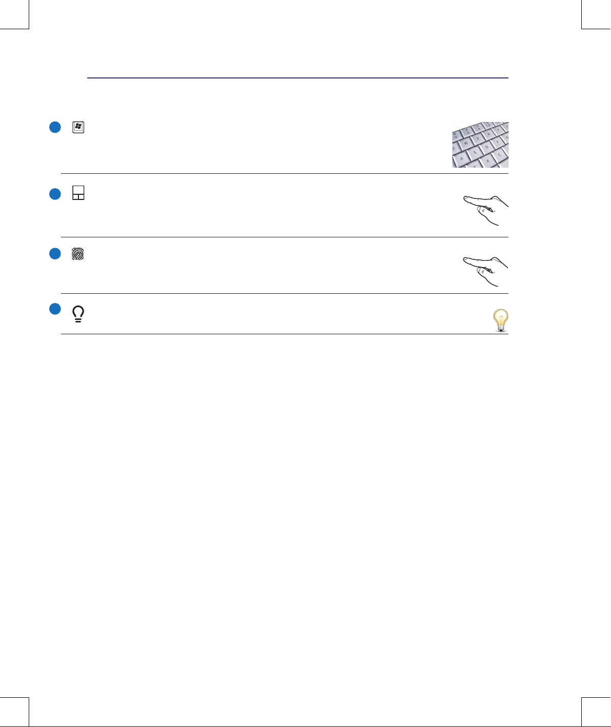
Keyboard
The keyboard provides full-sized keys with comfortable travel (depth at which the keys
can be depressed) and palm rest for both hands. Two Windows function keys are provided
to help ease navigation in the Windows operating system.
10
Fingerprint Scanner (on selected models)
The ngerprint scanner allows use of security software using your ngerprint as your
identication key.
11
Status Indicators (front)
Status indicators represent various hardware/software conditions. See indicator details in section 3.
12
13
15
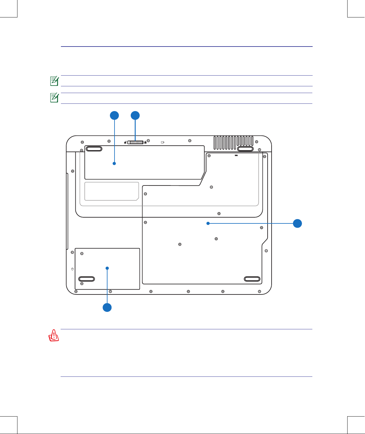
Knowing the Parts 2
Bottom Side
Refer to the illustration below to identify the components on this side of the Notebook PC.
1 2
3
4
WARNING! The bottom of the Notebook PC can get very hot. Be careful when handling the Notebook PC while it is in operation or recently been in operation. High
temperatures are normal during charging or operation. Do not use on soft surfaces
such as beds or sofas which may block the vents. DO NOT PUT THE NOTEBOOK
PC ON YOUR LAP OR OTHER PARTS OF THE BODY TO AVOID INJURY FROM THE
HEAT.
The bottom side may vary in appearance depending on model.
The battery pack size varies depending on model.
16
2 Knowing the Parts
1
2
3
4
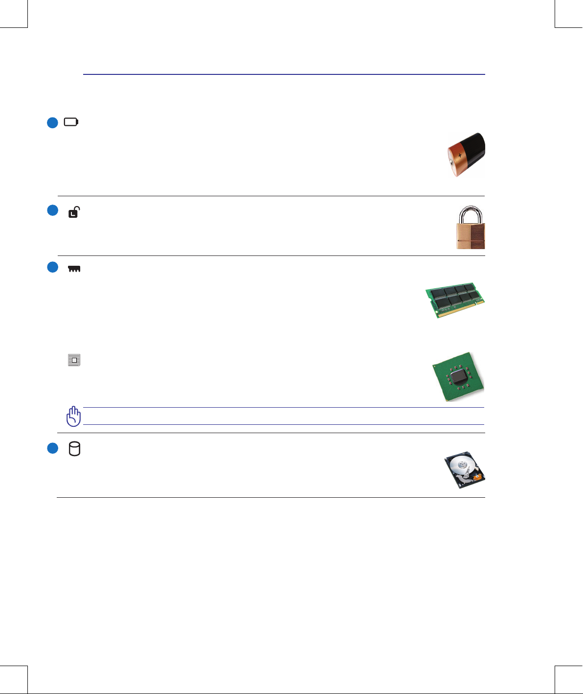
Battery Lock - Spring
The spring battery lock is used to keep the battery pack secured. When the battery pack is inserted, it will
automatically lock. To remove the battery pack, this spring lock must be held in the unlocked position.
Battery Pack
The battery pack is automatically charged when the Notebook PC is connected to an AC power
source and maintains power to the Notebook PC when AC power is not connected. This allows use
when moving temporarily between locations. Battery time varies by usage and by the specications
for this Notebook PC. The battery pack cannot be disassembled and must be purchased as a single
unit.
Central Processor Unit (CPU) Compartment
Some Notebook PC models feature a socketed-processor design to allow upgrading to faster
processors in the future. Some models feature a ULV design for compactness and may not
be upgraded. Visit an authorized service center or retailer for information on upgrades.
WARNING! End-user removal of the CPU or hard disk drive will void the warranty.
Memory (RAM) Compartment
The memory compartment provides expansion capabilities for additional memory. Additional
memory will increase application performance by decreasing hard disk access. The BIOS au-
tomatically detects the amount of memory in the system and congures accordingly. There is
no hardware or software (including BIOS) setup required after the memory is installed. Visit an
authorized service center or retailer for information on memory upgrades for your Notebook PC. Only purchase expansion modules from authorized retailers of this Notebook PC to ensure maximum compatibility and reliability.
Hard Disk Drive Compartment
The hard disk drive is secured in a compartment. Visit an authorized service center or retailer for
information on hard disk drive upgrades for your Notebook PC. Only purchase hard disk drives
from authorized retailers of this Notebook PC to ensure maximum compatibility and reliability.
17
Knowing the Parts 2
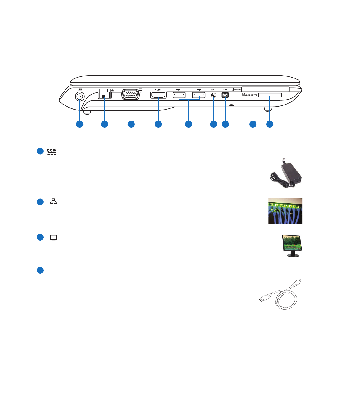
Left Side
Refer to the illustration below to identify the components on this side of the Notebook PC.
1 2 3 4 6 7 985
1
2
3
4
Power (DC) Input
The supplied power adapter converts AC power to DC power for use with this jack. Power supplied through this jack supplies power to the Notebook PC and charges the internal battery pack.
To prevent damage to the Notebook PC and battery pack, always use the supplied power
adapter. CAUTION: MAY BECOME WARM TO HOT WHEN IN USE. BE SURE
NOT TO COVER THE ADAPTER AND KEEP IT AWAY FROM YOUR BODY.
LAN Port
The RJ-45 LAN port with eight pins is larger than the RJ-11 modem port and supports
a standard Ethernet cable for connection to a local network. The built-in connector allows convenient use without additional adapters.
Display (Monitor) Output
The 15-pin D-sub monitor port supports a standard VGA-compatible device such as a monitor or projector to allow viewing on a larger external display.
HDMI Port
HDMI (High-Denition Multimedia Interface) is an uncompressed all-digital
audio/video interface between any audio/video source, such as a set-top box, DVD
player, and A/V receiver and an audio and/or video monitor, such as a digital tele-
vision (DTV). Supports standard, enhanced, or high-denition video, plus multichannel digital audio on a single cable. It transmits all ATSC HDTV standards and
supports 8-channel digital audio, with bandwidth to spare to accommodate future
enhancements or requirements.
HDMI
18
2 Knowing the Parts
5
6
7
2.0
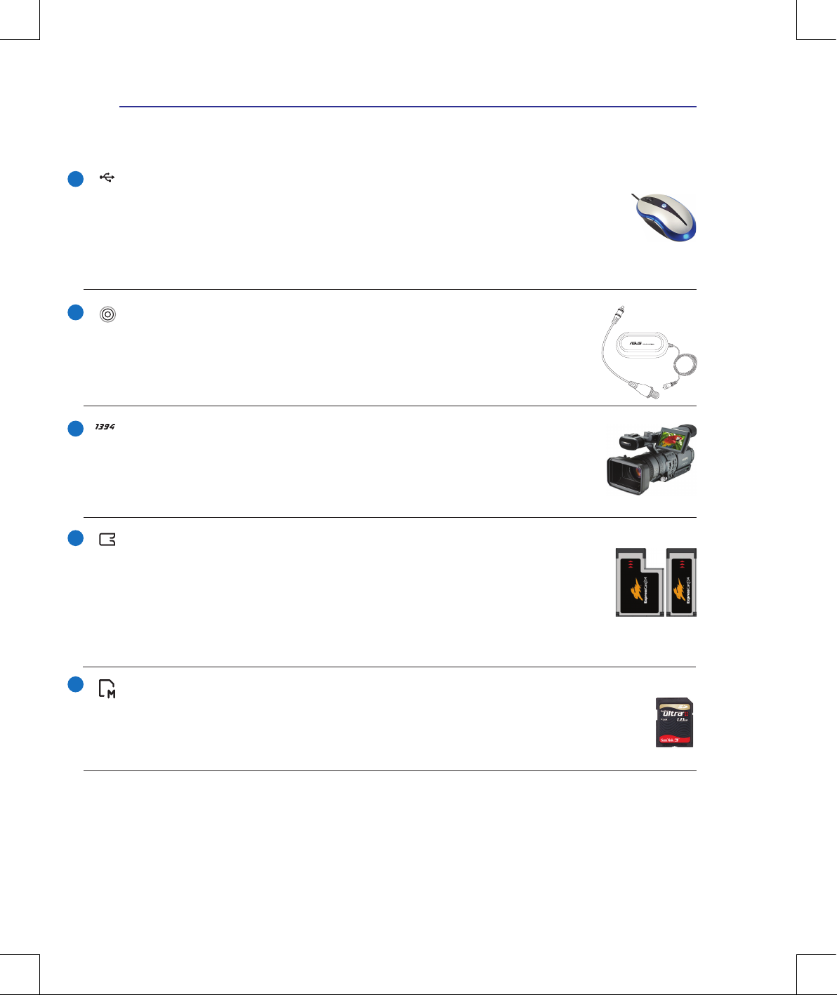
USB Port (2.0/1.1)
The USB (Universal Serial Bus) port is compatible with USB 2.0 or USB 1.1 devices such as
keyboards, pointing devices, cameras, hard disk drives, printers, and scanners connected in a
series up to 12Mbits/sec (USB 1.1) and 480Mbits/sec (USB 2.0). USB allows many devices to
run simultaneously on a single computer, with some peripherals acting as additional plug-in sites or
hubs. USB supports hot-swapping of devices so that most peripherals can be connected or disconnected
without restarting the computer.
Antenna Input (on selected models)
The antenna input is for TV (on selected models) frequency signal and allows for use
with the provided digital TV antenna or input from subscription television services. The
provided antenna can receive digital TV. Cable service connection can receive digital
TV, analog TV, depending on paid services. Note: Use the provided adapter for use
with coaxial connectors.
IEEE1394 Port (on selected models)
IEEE1394 is a high speed serial bus like SCSI but has simple connections and hotplugging capabilities like USB. The interface IEEE1394 has a bandwidth of 100-400
Mbits/sec and can handle up to 63 units on the same bus. IEEE1394 is also used in
high-end digital equipment and should be marked “DV” for Digital Video port.
Flash Memory Slot
Normally an external memory card reader must be purchased separately in order to use
memory cards from devices such as digital cameras, MP3 players, mobile phones, and PDAs.
This Notebook PC has a built-in high-speed memory card reader that can conveniently read
from and write to many ash memory cards as mentioned later in this manual.
ExpressCard Slot
One 26pin Express card slot is available to support one ExpressCard/34mm or one
ExpressCard/54mm expansion card. This new interface is faster by using a serial bus
supporting USB 2.0 and PCI Express instead of the slower parallel bus used in the PC
card slot. (Not compatible with previous PCMCIA cards.)
The dummy expansion card that comes with the Notebook PC can function as a memory card holder
(on selected models), which protects the conductors of your ash memory card.
8
9
19
Knowing the Parts 2
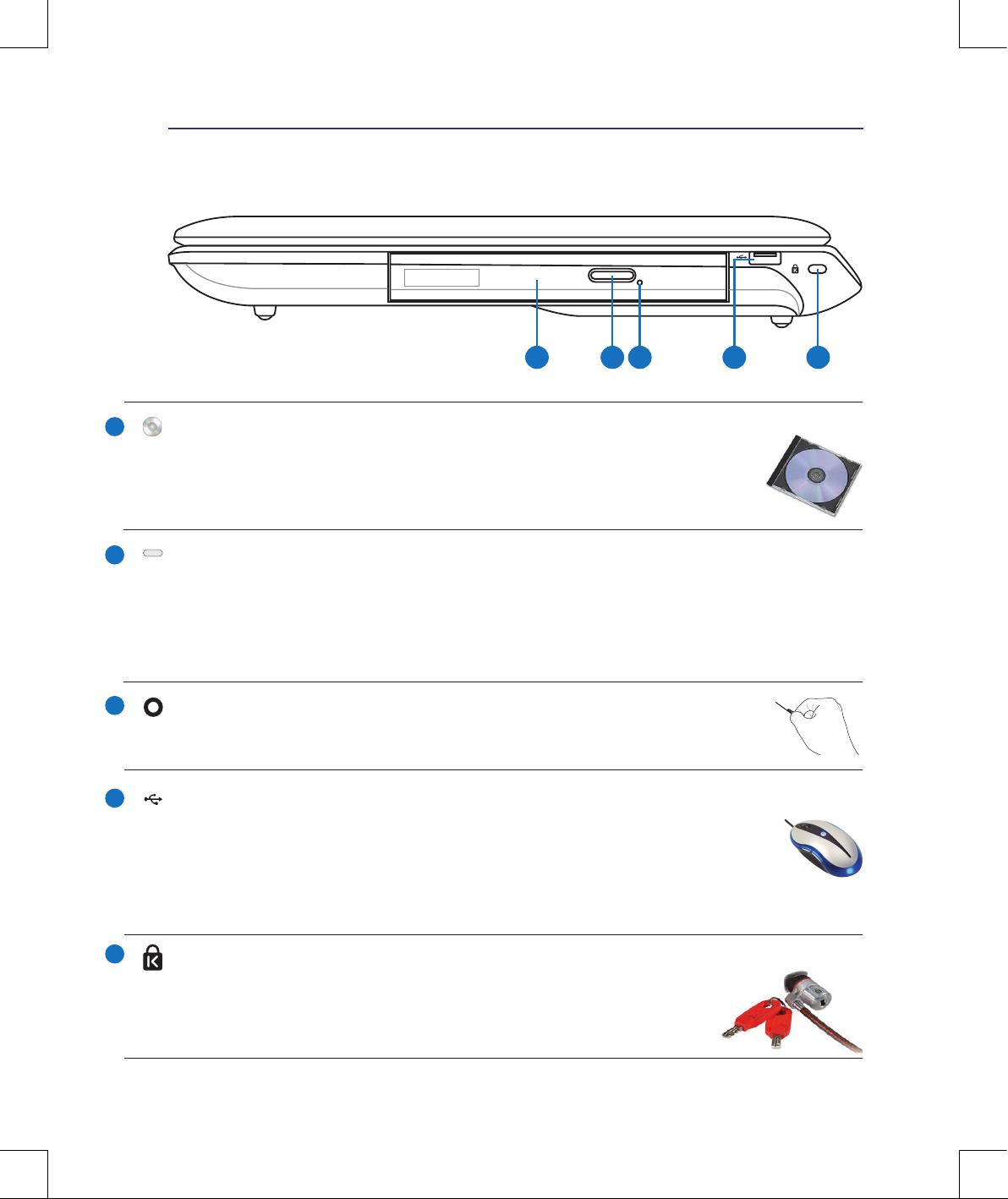
Right Side
Refer to the illustration below to identify the components on this side of the Notebook PC.
1 2 43 5
Optical Drive Emergency Eject (location varies by model)
The emergency eject is used to eject the optical drive tray in case the electronic eject
does not work. Do not use the emergency eject in place of the electronic eject.
Optical Drive
The Notebook PC comes in various models with different optical drives. The Note-
book PC’s optical drive may support compact discs (CD) and/or digital video discs
(DVD) and may have recordable (R) or re-writable (RW) capabilities. See the marketing specications for details on each model.
Optical Drive Electronic Eject
The optical drive eject has an electronic eject button for opening the tray. You can also eject the optical
drive tray through any software player or by right clicking the optical drive in Windows “Computer”
and selecting Eject. This eject also functions as the optical drive activity indicator which shows when
data is being transferred by the optical disk drive. This indicator will light in proportion to the data
size transferred.
2.0
USB Port (2.0/1.1)
The USB (Universal Serial Bus) port is compatible with USB 2.0 or USB 1.1 devices such as
keyboards, pointing devices, cameras, hard disk drives, printers, and scanners connected in a
series up to 12Mbits/sec (USB 1.1) and 480Mbits/sec (USB 2.0). USB allows many devices to
run simultaneously on a single computer, with some peripherals acting as additional plug-in sites or
hubs. USB supports hot-swapping of devices so that most peripherals can be connected or disconnected
without restarting the computer.
1
2
3
4
5
Kensington® Lock Port
The Kensington® lock port allows the Notebook PC to be secured using Kensington® compatible Notebook PC security products. These security products usually include a metal
cable and lock that prevent the Notebook PC to be removed from a xed object.
Some may also include a motion detector to sound an alarm when moved.
20
2 Knowing the Parts
1
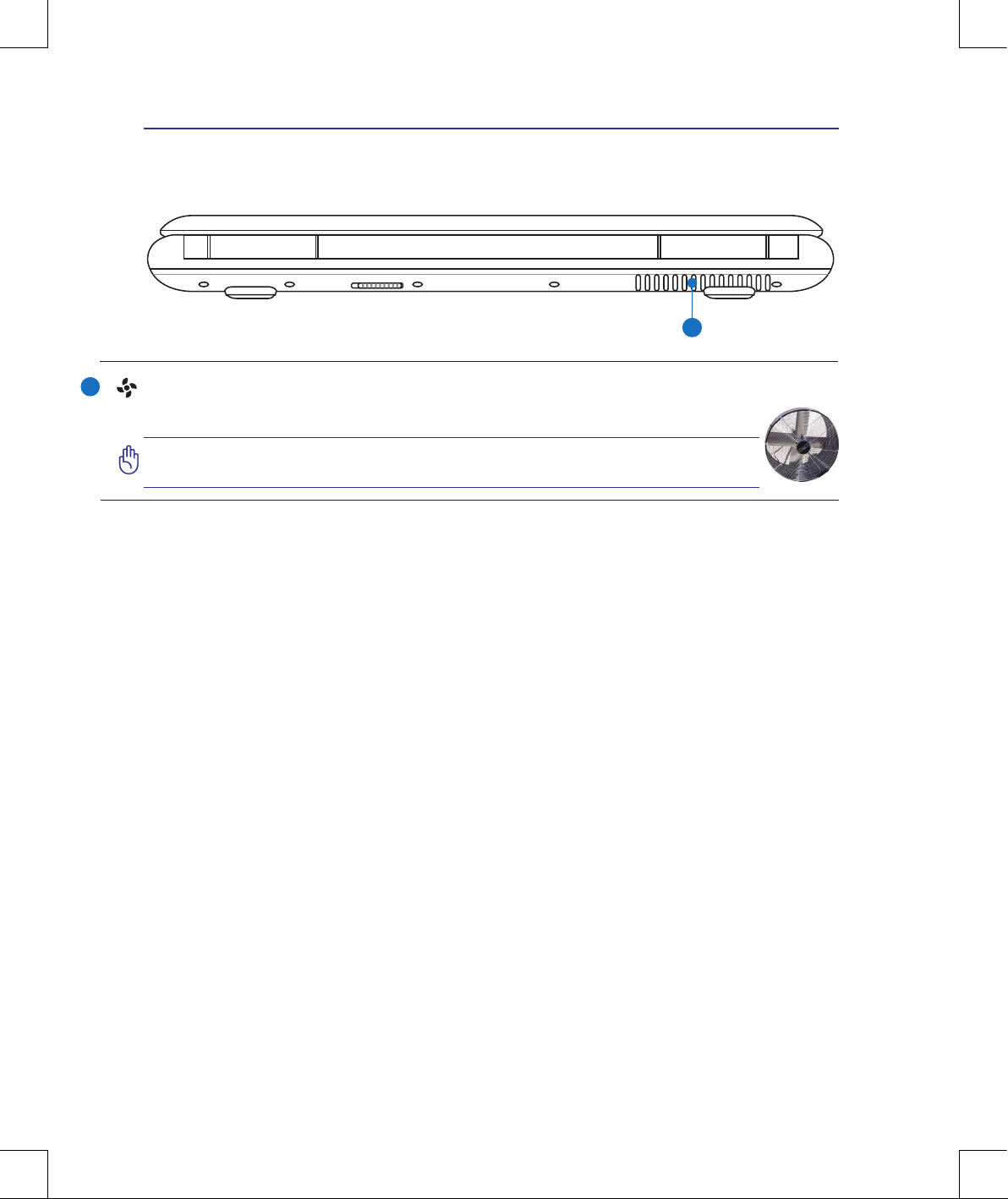
Rear Side
Refer to the illustration below to identify the components on this side of the Notebook PC.
1
Air Vents
The air vents allow cool air to enter and warm air to exit the Notebook PC.
IMPORTANT! Make sure that paper, books, clothing, cables, or other objects do not block any of the air vents or else overheating may occur.
21
Knowing the Parts 2
3
4
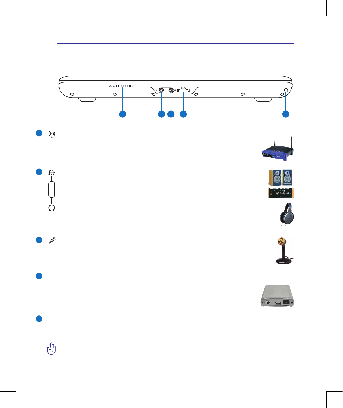
Wireless Switch
Enables or disables the built-in wireless LAN and Bluetooth (selected models). When
enabled, the wireless status indicator will light. Windows software settings are necessary before use.
SPDIF Output Jack
This jack provides connection to SPDIF (Sony/Philips Digital Interface) compliant devices for digital audio output. Use this feature to turn the Notebook PC into a hi- home
entertainment system.
Headphone Output Jack
The stereo headphone jack (1/8 inch) is used to connect the Notebook PC’s audio out signal to
amplied speakers or headphones. Using this jack automatically disables the built-in speakers.
Combo
Microphone Input Jack
The mono microphone jack (1/8 inch) can be used to connect an external microphone or output signals from audio devices. Using this jack automatically disables the built-in microphone.
Use this feature for video conferencing, voice narrations, or simple audio recordings.
5
Front Side
Refer to the illustration below to identify the components on this side of the Notebook PC.
1 2 3 4 5
E-SATA Port (on selected models)
External SATA or eSATA allows external connection of Serial-ATA devices originally
designed for use inside the computer. It is up to six times faster than existing USB 2.0,
& 1394 for external storage solutions and is also hot pluggable using shielded cables and
connectors up to two meters.
E-SATA
1
2
Air Ionizer (on selected models)
The built-in air ionizer functions as an air purier. The emitted ions purify the air by attracting particles oating in
the air and falling to the ground. Press the Air Ionizer instant key to activate this function.
IMPORTANT! DO NOT insert any object into the ionizer hole. Doing so will damage
the air ionizer.

22
2 Knowing the Parts

23
3. Getting Started
Using AC Power
Using Battery Power
Powering ON the Notebook PC
Checking Battery Power
Powering Options
Power Management Modes
Special Keyboard Functions
Switches and Status Indicators
Photos and icons in this manual are used for artistic purposes only and do not
show what is actually used in the product itself.
There may be differences between your Notebook PC and the drawings shown in
this manual. Please accept your Notebook PC as being correct.
24
3 Getting Started
IMPORTANT! Damage may occur if you use a different adapter to power the Notebook PC or use the Notebook PC’s adapter to power other electrical devices. If
there is smoke, burning scent, or extreme heat coming from the AC-DC adapter,
seek servicing. Seek servicing if you suspect a faulty AC-DC adapter. You may damage both your battery pack(s) and the Notebook PC with a faulty AC-DC adapter.
This Notebook PC may come with either a two or three-prong plug depending on
territory. If a three-prong plug is provided, you must use a grounded AC outlet or
use a properly grounded adapter to ensure safe operation of the Notebook PC.
WARNING! THE POWER ADAPTER MAY BECOME WARM TO HOT WHEN IN USE.
BE SURE NOT TO COVER THE ADAPTER AND KEEP IT AWAY FROM YOUR BODY.
You can buy travel kits for the Notebook PC that includes power and modem adapters for almost every country.
1
2
3
Power System
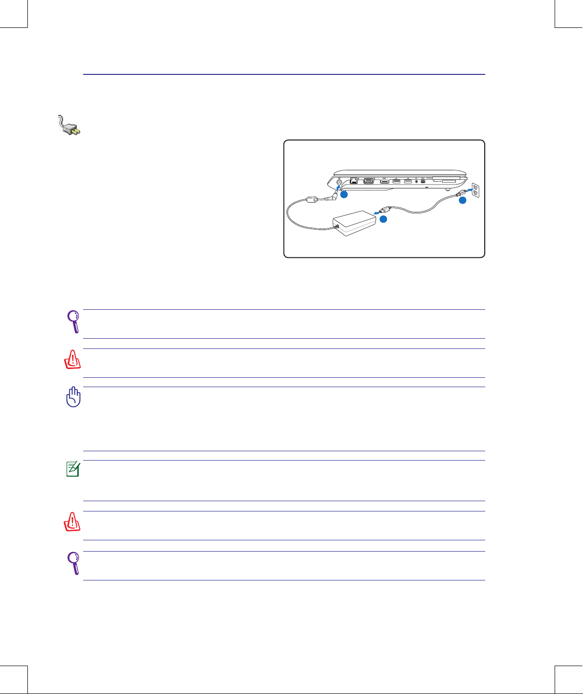
Using AC Power
The Notebook PC power is comprised of two
parts, the power adapter and the battery power
system. The power adapter converts AC power
from a wall outlet to the DC power required by
the Notebook PC. Your Notebook PC comes with
a universal AC-DC adapter. That means that you
may connect the power cord to any 100V-120V
as well as 220V-240V outlets without setting
switches or using power converters. Different
countries may require that an adapter be used
to connect the provided US-standard AC power
cord to a different standard. Most hotels will
provide universal outlets to support different power cords as well as voltages. It is always best to ask
an experienced traveler about AC outlet voltages when bringing power adapters to another country.
Unplug the power adapter or switch off the AC outlet to minimize the power consumption when the Notebook PC is not in use.
WARNING! DO NOT connect the AC power cord to an AC outlet prior to connecting
the DC plug to the Notebook PC. Doing so may damage the AC-DC adapter.
25
Getting Started 3
IMPORTANT! Never attempt to remove the battery pack while the Notebook PC is
turned ON, as this may result in the loss of working data.
IMPORTANT! Only use battery packs and power adapters supplied with this Note-
book PC or specically approved by the manufacturer or retailer for use with this
model or else damage may occur to the Notebook PC.
1
3
2
5
4
1
3
2
5
4
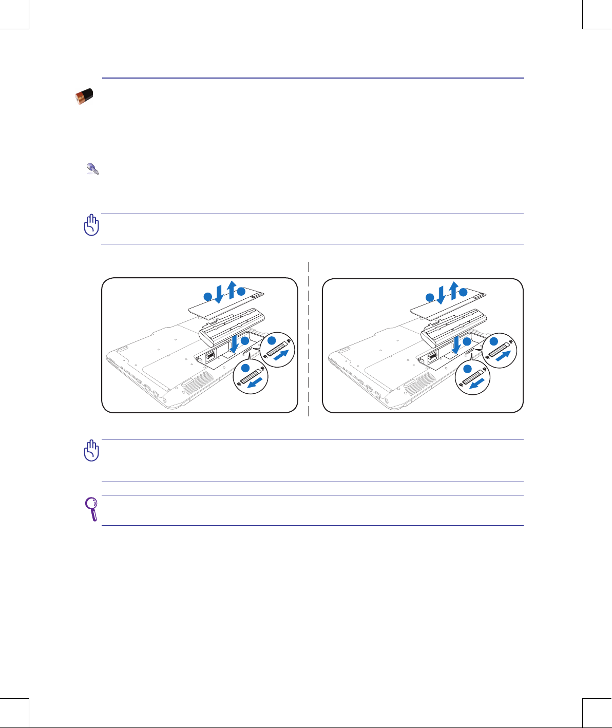
To install the battery pack:
To remove the battery pack:
Using Battery Power
The Notebook PC is designed to work with a removable battery pack. The battery pack consists of
a set of battery cells housed together. A fully charged pack will provide several hours of battery life,
which can be further extended by using power management features through the BIOS setup. Additional battery packs are optional and can be purchased separately through a Notebook PC retailer.
Installing and Removing the Battery Pack
Your Notebook PC may or may not have its battery pack installed. If your Notebook PC does not have
its battery pack installed, use the following procedures to install the battery pack.
Ensure that the pull tab of the battery pack is not blocked when installing the battery pack, or there might be trouble removing the battery pack.
26
3 Getting Started
WARNING! For safety reasons, DO NOT throw the battery in re, DO NOT
short circuit the contacts, and DO NOT disassemble the battery. If there is
any abnormal operation or damage to the battery pack caused by impact,
turn OFF the Notebook PC and contact an authorized service center.
Battery Care
The Notebook PC’s battery pack, like all rechargeable batteries, has a limit on the number times it can
be recharged. The battery pack’s useful life will depend on your environment temperature, humidity,
and how your Notebook PC is used. It is ideal that the battery be used in a temperature range be-
tween 5˚C and 35˚C (41˚F and 95˚F). You must also take into account that the Notebook PC’s internal
temperature is higher than the outside temperature. Any temperatures above or below this range will
shorten the life of the battery. But in any case, the battery pack’s usage time will eventually decrease
and a new battery pack must be purchased from an authorized dealer for this Notebook PC. Because
batteries also have a shelf life, it is not recommended to buy extras for storing.
27
Getting Started 3
IMPORTANT! If warnings are still given during bootup after running a software disk
checking utility, you should take your Notebook PC in for servicing. Continued use
may result in data loss.
IMPORTANT! To protect the hard disk drive, always wait at least 5 seconds after
turning OFF your Notebook PC before turning it back ON.
WARNING! DO NOT carry or cover a Notebook PC that is powered ON with any materials that will reduce air circulation such as a carrying bag.
Before bootup, the display panel ashes when the power is turned ON. This is part
of the Notebook PC’s test routine and is not a problem with the display.
Powering ON the Notebook PC
The Notebook PC’s power-ON message appears on the screen when you turn it ON. If necessary, you
may adjust the brightness by using the hot keys. If you need to run the BIOS Setup to set or modify
the system conguration, press [F2] upon bootup to enter the BIOS Setup. If you press [Tab] during
the splash screen, standard boot information such as the BIOS version can be seen. Press [ESC] and
you will be presented with a boot menu with selections to boot from your available drives.
The Power-On Self Test (POST)
When you turn ON the Notebook PC, it will rst run through a series of software-controlled diagnostic tests called the Power-On Self Test (POST). The software that controls the POST is installed
as a permanent part of the Notebook PC’s architecture. The POST includes a record of the Notebook
PC’s hardware conguration, which is used to make a diagnostic check of the system. This record is
created by using the BIOS Setup program. If the POST discovers a difference between the record and
the existing hardware, it will display a message on the screen prompting you to correct the conict by
running BIOS Setup. In most cases the record should be correct when you receive the Notebook PC.
When the test is nished, you may get a message reporting “No operating system found” if the hard
disk was not preloaded with an operating system. This indicates that the hard disk is correctly detected
and ready for the installation of a new operating system.
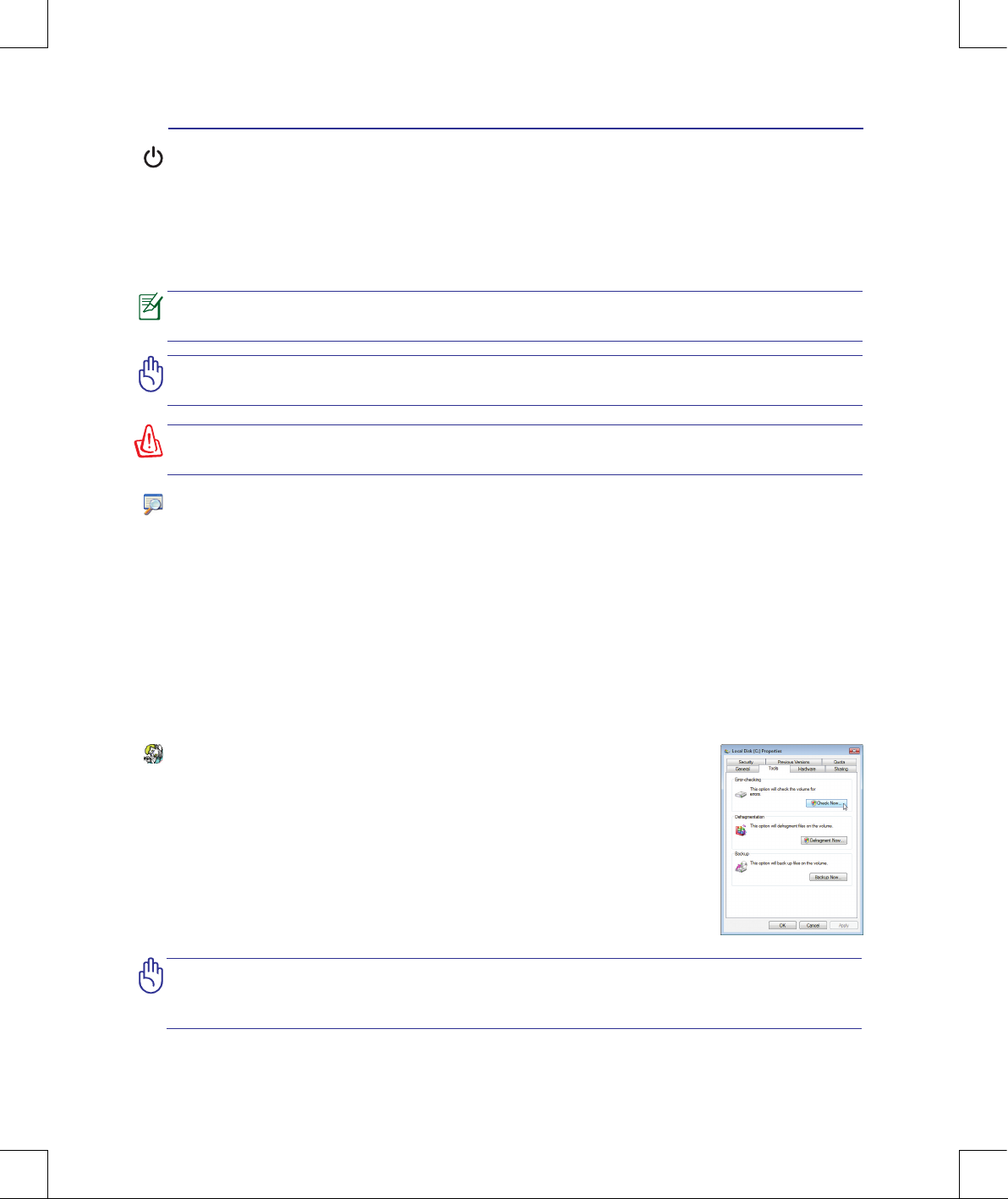
Self Monitoring and Reporting Technology
The S.M.A.R.T. (Self Monitoring and Reporting Technology) checks the hard
disk drive during POST and gives a warning message if the hard disk drive requires servicing. If any critical hard disk drive warning is given during bootup,
backup your data immediately and run Windows disk checking program. To run
Window’s disk checking program: click Start > select Computer > right-click
a hard disk drive icon > choose Properties > click the Tools tab > click Check
Now > click Start. You can also select “Scan ... sectors” for more effective scan
and repair but the process will run slower.
28
3 Getting Started
You will be warned when
battery power is low. If you
continue to ignore the low
battery warnings, the Notebook PC eventually enters
suspend mode (Windows
default uses STR).
WARNING! Suspend-to-RAM (STR) does not last long when the battery power is depleted. Suspend-to-Disk (STD) is not the same as power OFF. STD requires a small
amount of power and will fail if no power is available due to complete battery depletion or no power supply (e.g. removing both the power adapter and battery pack).
Screen captures shown
here are examples only and
may not reect what you
see in your system.
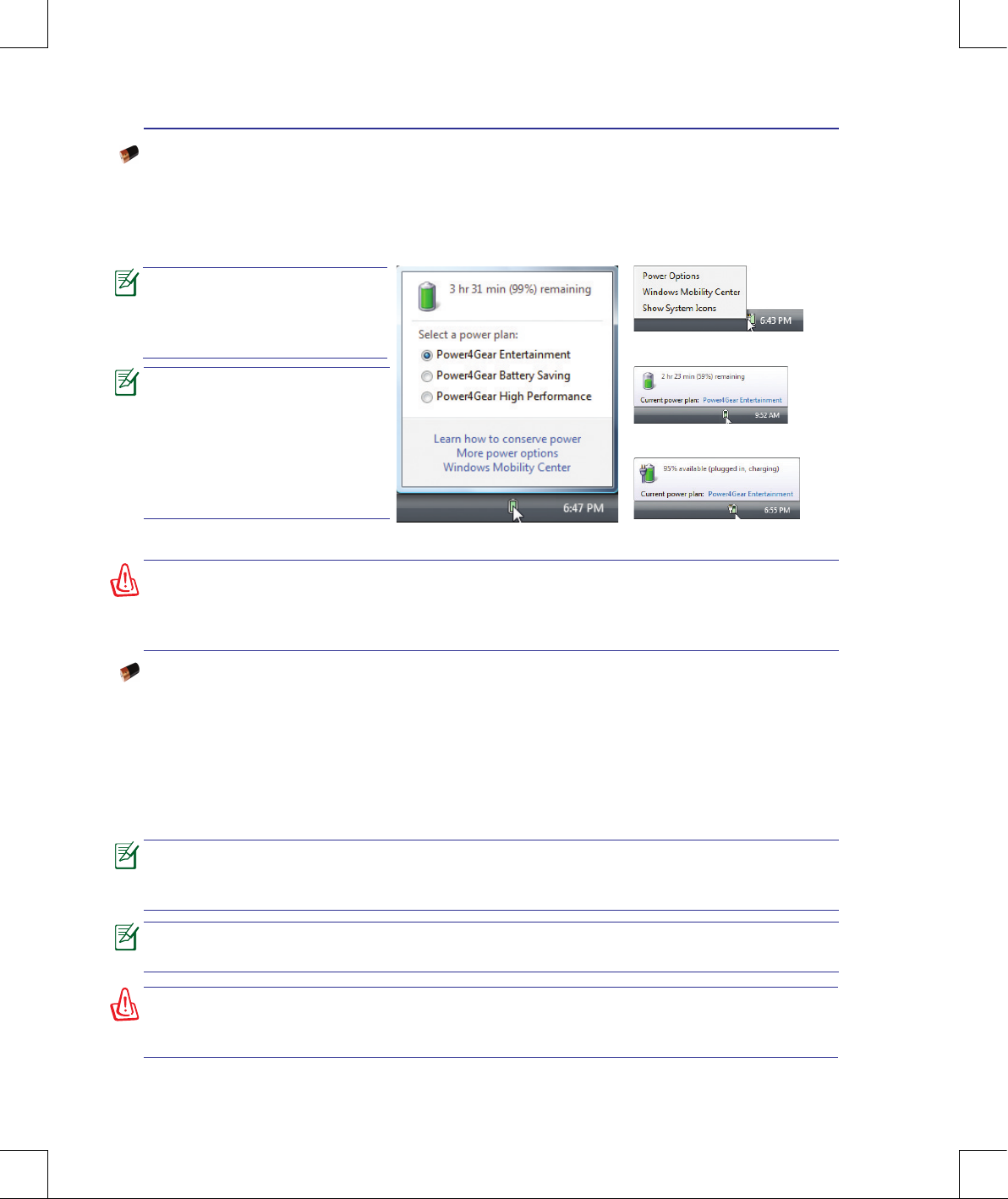
Checking Battery Power
The battery system implements the Smart Battery standard under the Windows environment, which
allows the battery to accurately report the amount of charge left in the battery. A fully-charged battery
pack provides the Notebook PC a few hours of working power. But the actual gure varies depending
on how you use the power saving features, your general work habits, the CPU, system memory size,
and the size of the display panel.
Left-click the battery icon
Pointer over the battery icon without
power adapter�
Pointer over the battery icon with
power adapter�
Right-click the battery icon
WARNING! DO NOT leave the battery pack discharged. The battery pack will discharge over time. If not using a battery pack, it must continued to be charged every
three months to extend recovery capacity or else it may fail to charge in the future.
The battery stops charging if the temperature is too high or the battery voltage is
too high.
Charging the Battery Pack
Before you use your Notebook PC on the road, you will have to charge the battery pack. The battery
pack begins to charge as soon as the Notebook PC is connected to external power using the power
adapter. Fully charge the battery pack before using it for the rst time. A new battery pack must
completely charge before the Notebook PC is disconnected from external power. It takes a few hours
to fully charge the battery when the Notebook PC is turned OFF and may take twice the time when
the Notebook PC is turned ON. The battery status indicator on the Notebook PC turns OFF when the
battery pack is charged.
The battery starts charging when the charge remaining in the battery drops below
95%. This prevents the battery from charging frequently. Minimizing the recharge
cycles helps prolong battery life.
29
Getting Started 3
IMPORTANT! To protect the hard drive, wait at least 5 seconds after turning OFF
your Notebook PC before turning it back ON.
IMPORTANT! Do not use emergency
shutdown while data is being written;
doing so can result in loss or destruction of your data.
Emergency Shutdown
In case your operating system cannot properly turn OFF or restart, there is an additional way to shutdown your Notebook PC:
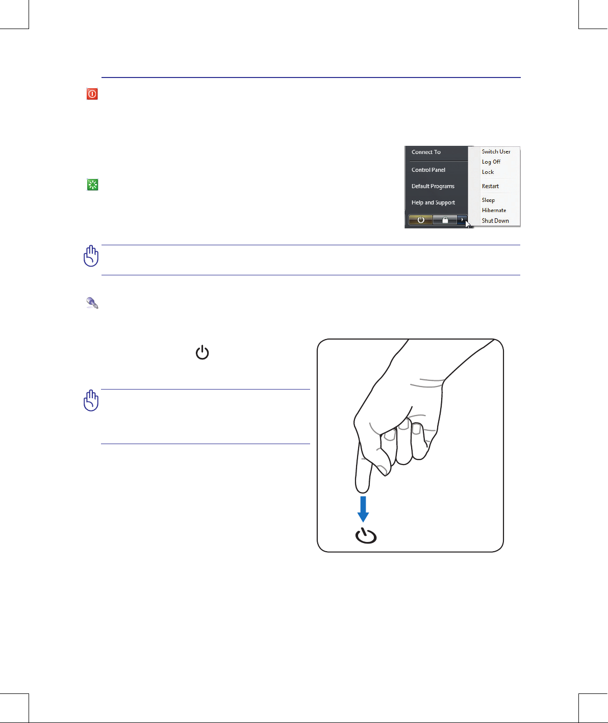
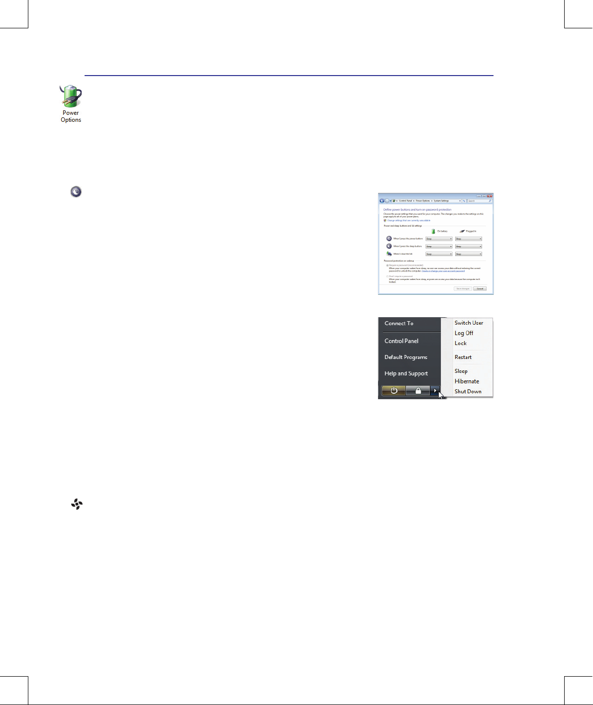
Power Options
The power switch turns ON and OFF the Notebook PC or putting the Notebook PC into sleep or
hibernation modes. Actual behavior of the power switch can be customized in Windows Control Panel
“Power Options.”
For other options, such as “Switch User, Restart, Sleep, or Shut Down,”
click the arrowhead next to the lock icon.
Restarting or Rebooting
After making changes to your operating system, you may be prompted
to restart the system. Some installation processes will provide a dialog
box to allow restart. To restart the system manually, choose Restart.
Hold the power button over 4 seconds.
30
3 Getting Started
Thermal Power Control
There are three power control methods for controlling the Notebook PC’s thermal state. These power
control cannot be congured by the user and should be known in case the Notebook PC should enter
these states. The following temperatures represent the chassis temperature (not CPU).
• The fan turns ON for active cooling when the temperature reaches the safe upper limit.
• The CPU decreases speed for passive cooling when the temperature exceeds the safe upper limit.
• The system shut down for critical cooling when temperature exceeds the maximum safe upper
limit.
Sleep and Hibernate
Power management settings can be found in the Windows > Control
Panel > Power Options. In System Settings, you can dene “Sleep/
Hibernate” or “Shut Down” for closing the display panel or pressing
the power button. “Sleep” and “Hibernate” saves power when your
Notebook PC is not in use by turning OFF certain components. When
you resume your work, your last status (such as a document scrolled
down half way or email typed half way) will reappear as if you never
left. “Shut Down” will close all applications and ask if you want to save
your work if any are not saved.
Hibernate is the same as Suspend-to-Disk (STD) and stores your current data and status on the hard
disk drive. By doing this, RAM does not have to be periodically refreshed and power consumption is
greatly reduced but not completely eliminated because certain wake-up components like LAN needs
to remain powered. “Hibernate” saves more power compared to “Sleep”. Click the Start button and
the arrowhead next to the lock icon to see this option. Recover by pressing the power button. (NOTE:
The power indicator will be OFF in this mode.)
Sleep is the same as Suspend-to-RAM (STR). This function stores your
current data and status in RAM while many components are turned
OFF. Because RAM is volatile, it requires power to keep (refresh) the
data. Click the Start button and the arrowhead next to the lock icon
to see this option. You can also use the keyboard shortcut [Fn F1] to
activate this mode. Recover by pressing any keyboard key except [Fn].
(NOTE: The power indicator will blink in this mode.)
Power Management Modes
The Notebook PC has a number of automatic or adjustable power saving features that you can use to
maximize battery life and lower Total Cost of Ownership (TCO). You can control some of these features through the Power menu in the BIOS Setup. ACPI power management settings are made through
the operating system. The power management features are designed to save as much electricity as possible by putting components into a low power consumption mode as often as possible but also allow
full operation on demand.
 Loading...