

Page 1

User Manual
®
E2698/ July 2006
GigaX1024i+
Layer 2 Smart Plus Switch
Page 2

ii
Copyright © 2006 ASUSTeK COMPUTER INC. All Rights Reserved.
No part of this manual, including the products and software described in it, may
be reproduced, transmitted, transcribed, stored in a retrieval system, or translated
into any language in any form or by any means, except documentation kept by the
purchaser for backup purposes, without the express written permission of ASUSTeK
COMPUTER INC. (ASUS).
Product warranty or service will not be extended if: (1) the product is repaired,
modied or altered, unless such repair, modication of alteration is authorized in
writing by ASUS; or (2) the serial number of the product is defaced or missing.
ASUS provides this manual “as is” without warranty of any kind, either express
or implied, including but not limited to the implied warranties or conditions of
merchantability or fitness for a particular purpose. In no event shall ASUS, its
directors, ofcers, employees, or agents be liable for any indirect, special, incidental,
or consequential damages (including damages for loss of prots, loss of business,
loss of use or data, interruption of business and the like), even if ASUS has been
advised of the possibility of such damages arising from any defect or error in this
manual or product.
Sp ec if ic ations and information contained in this ma nu al a re f ur ni sh ed for
informational use only, and are subject to change at any time without notice,
and should not be construed as a commitment by ASUS. ASUS assumes no
responsibility or liability for any errors or inaccuracies that may appear in this
manual, including the products and software described in it.
Products and corporate names appearing in this manual may or may not be
registered trademarks or copyrights of their respective companies, and are used
only for identication or explanation and to the owners’ benet, without intent to
infringe.
E2698
First Edition
July 2006
Copyright Information
Page 3

iii
Contact Information
ASUSTeK COMPUTER INC.
Company address: 15 Li-Te Road, Beitou, Taipei 11259
General (tel): +886-2-2894-3447
Web site address: www.asus.com.tw
General (fax): +886-2-2894-7798
General email: info@asus.com.tw
Technical support
General support (tel): +886-2-2894-3447
Online support: http://support.asus.com
ASUS COMPUTER INTERNATIONAL (America)
Company address: 44370 Nobel Drive, Fremont, CA 94538, USA
General (fax): +1-510-608-4555
Web site address: usa.asus.com
Technical support
General support (tel): +1-502-995-0883
Online support: http://support.asus.com
Notebook (tel): +1-510-739-3777 x5110
Support (fax): +1-502-933-8713
ASUS COMPUTER GmbH (Germany & Austria)
Company address: Harkort Str. 25, D-40880 Ratingen, Germany
General (tel): +49-2102-95990
Web site address: www.asus.com.de
General (fax): +49-2102-959911
Online contact: www.asus.com.de/sales
Technical support
Component support: +49-2102-95990
Online support: http://support.asus.com
Notebook support: +49-2102-959910
Support (fax): +49-2102-959911
Page 4

iv
Table of Contents
1 Introduction ............................................................1
1.1 Conventions in this manual ......................................1
1.1.1 Notational conventions ............................................... 1
1.1.2 Typographical conventions ......................................... 1
1.1.3 Symbols ..................................................................... 1
1.2 Package contents .....................................................2
1.3 Features ...................................................................3
1.4 Front panel features .................................................4
1.5 Rear panel features ..................................................5
2 Quick Start .............................................................6
2.1 Part 1 — Installing the switch ...................................6
2.1.1 Installing on a at surface .......................................... 6
2.1.2 Installing on a rack .................................................... 7
2.2 Part 2 — Connecting the hardware ...........................7
2.2.1 Connect to the computers or LAN .............................. 8
2.2.2 Attach the power adapter ........................................... 8
2.3 Part 3 — Basic switch settings .................................9
2.3.1 Setting up thru the Conguration Manager ............... 9
3 Using the Conguration Manager ...................... 11
3.1 Login to the Conguration Manager ........................ 11
3.1.1 Setting up the Conguration Manager ......................11
3.1.2 Setting up a new IP address ................................... 12
3.2 Functional Layout ....................................................13
3.2.1 Menu navigation ....................................................... 14
3.2.2 Commonly used buttons and icons .......................... 14
Page 5

v
4 Conguration Management ................................15
4.1 System ...................................................................15
4.1.1 Management ........................................................... 16
4.1.2 IP Setup ................................................................... 16
4.1.3 Administration .......................................................... 16
4.1.4 Reboot ..................................................................... 17
4.1.5 Firmware Upgrade ................................................... 18
4.2 Physical Interface ...................................................19
4.3 Bridge ......................................................................20
4.3.1 Spanning Tree .......................................................... 20
4.3.2 Link Aggregation ...................................................... 21
4.3.3 Mirroring .................................................................. 22
4.3.4 Static Multicast ........................................................ 23
4.3.5 IGMP Snooping ....................................................... 23
4.3.6 Bandwidth Control ................................................... 24
4.3.7 Dynamic Addresses ................................................. 25
4.3.8 Static Addresses ...................................................... 25
4.3.9 VLAN ....................................................................... 26
4.3.10 Default Port VLAN and CoS .................................. 29
4.4 SNMP Setup
............................................................
30
4.4.1 Community Table ..................................................... 30
4.4.2 Host Table ................................................................ 30
4.4.3 Trap Setting ............................................................. 30
4.4.4 VACM Group ............................................................ 31
4.4.5 VACM View ............................................................... 31
4.4.6 USM User ................................................................ 32
4.5 Security ...................................................................33
4.5.1 Port Access Control ................................................. 33
4.5.2 Dial-In User ............................................................. 34
Page 6

vi
4.5.3 RADIUS ................................................................... 35
4.5.4 Port Security ............................................................ 35
4.6 QoS .........................................................................39
4.6.1 Trust State ............................................................... 39
4.6.2 Mapping ................................................................... 39
4.6.3 Priority Override ....................................................... 40
4.6.4 CoS ......................................................................... 41
4.7 Cable Diagnosis .......................................................42
4.8 Statistics Chart ........................................................42
4.8.1 Trafc Comparison .................................................. 42
4.8.2 Error Group ............................................................. 43
4.8.3 Historical Data ......................................................... 43
4.9 Save Conguration ..................................................43
5 IP Addresses, Network Masks & Subnets .......44
5.1 IP Addresses ............................................................44
5.1.1 Structure of an IP address ....................................... 44
5.1.2 Network classes ...................................................... 45
5.2 Subnet masks ..........................................................46
6 Troubleshooting .................................................. 47
6.1 Diagnosing problems using IP utilities ......................47
6.1.1 ping .......................................................................... 47
6.1.2 nslookup .................................................................. 48
6.2 Simple xes .............................................................49
6.3 Files upload and download procedure .....................51
6.3.1 Upload rmware by FTP .......................................... 52
6.3.2 Upload auto-cong by FTP ..................................... 51
6.3.3 Backup system congurations by FTP .................... 52
6.3.4 Restore system congurations by FTP ................... 53
7 Glossary .............................................................. 54
Page 7

vii
List of Figures
Figure 1 GigaX L2 Smart Plus
Switch Package Contents ................................................ 2
Figure 2 Front Panel ...................................................................... 4
Figure 3 Rear Panel ...................................................................... 5
Figure 4 Overview of Hardware Connections ................................ 7
Figure 5 Login Screen ................................................................... 9
Figure 6 IP Setup .......................................................................... 10
Figure 7 Conguration Manager Login Screen..............................11
Figure 8 Home Page ................................................................... 12
Figure 9 IP Setup ......................................................................... 12
Figure 10 Functional Layout ........................................................ 13
Figure 11 Expanded Menu List .................................................... 14
Figure 12 Management ............................................................... 16
Figure 13 Administration .............................................................. 17
Figure 14 Reboot ......................................................................... 17
Figure 15 Firmware Upgrade ....................................................... 18
Figure 16 Physical Interface ......................................................... 19
Figure 17 Spanning tree .............................................................. 20
Figure 18 Link aggregation .......................................................... 21
Figure 19 Mirroring page .............................................................. 22
Figure 20 Static Multicast ............................................................ 23
Figure 21 IGMP Snooping ........................................................... 23
Figure 22 Bandwidth control ........................................................ 24
Figure 23 Dynamic address ......................................................... 25
Figure 24 Static address .............................................................. 25
Figure 25 VLAN mode ................................................................ 26
Figure 26 Tagged VLAN .............................................................. 27
Page 8

viii
Figure 27 Port-Based VLAN ........................................................ 29
Figure 28 Default Port VLAN & Cos ............................................. 29
Figure 29 Community Table .......................................................... 30
Figure 30 Host Table .................................................................... 30
Figure 31 Trap Setting .................................................................. 30
Figure 32 VACM Group ................................................................ 31
Figure 33 VACM View .................................................................. 31
Figure 34 USM User ..................................................................... 32
Figure 35 Port Access Control ..................................................... 33
Figure 36 Dial-in User................................................................... 34
Figure 37 RADIUS ...................................................................... 35
Figure 38 Port Conguration ....................................................... 36
Figure 39 Port Status ................................................................... 37
Figure 40 Secure MAC addresses ............................................... 38
Figure 41 Trust state .................................................................... 39
Figure 42 Mapping ....................................................................... 39
Figure 43 Priority override ........................................................... 40
Figure 44 CoS .............................................................................. 41
Figure 45 Cable Diagnosis ........................................................... 42
Figure 46 Trafc Comparison ....................................................... 42
Figure 47 Error Group .................................................................. 43
Figure 48 Historical Status ......................................................... 43
Figure 49 Save Conguration ...................................................... 43
Figure 50 Using the ping Utility .................................................... 47
Figure 51 Upload Firmware by FTP ............................................. 51
Figure 52 Upload Auto-Cong by FTP ......................................... 51
Figure 53 Backup System Congurations by FTP ....................... 52
Figure 54 Restore System Congurations by FTP ...................... 53
Page 9

ix
List of Tables
Table 1 Front Panel Label and LEDs ............................................. 4
Table 2 Rear Panel Labels ............................................................. 5
Table 3 Technical Specications .................................................... 5
Table 4 LED Indicators ................................................................... 8
Table 5 Port Color Description ..................................................... 13
Table 6 Commonly Used Buttons and Icons................................. 14
Table 7 IP Address Structure ....................................................... 45
Table 8 Problems and Suggested Actions ................................... 51
Page 10

1
Chapter 1 - Introduction
ASUS GigaX 1024i+
1 Introduction
Thank you for buying a GigaX L2 Smart Plus Switch!
You can now manage your LAN through a friendly and powerful user
interface. This user manual will show you how to set up the GigaX L2
Smart Plus Switch, and how to customize its conguration to get the most
out of this product.
1.1 Conventions used in this manual
1.1.1 Notational conventions
• Acronyms are dened the rst time they appear in the text.
• The Asus GigaX L2 Smart Plus Switch is simply referred to as “
the
switch
”.
• The terms
LAN
and
network
are used interchangeably to
refer to a group of Ethernet-connected computers at one site.
1.1.2 Typographical conventions
•
Boldface
type text is used for items you select from menus and drop-
down lists, and commands you type when prompted by the program.
1.1.3 Symbols
This document uses the following icons to call your attention to specic
instructions or explanations.
Note: Provides clarication or non-essential information on
the current topic.
Denition: Explains terms or acronyms that may be
unfamiliar to many readers. These terms are also included
in the Glossary.
Warning: Provides messages of high importance, including
messages relating to personal safety or system integrity.
Page 11
2
Chapter 1 - Introduction
ASUS GigaX 1024i+
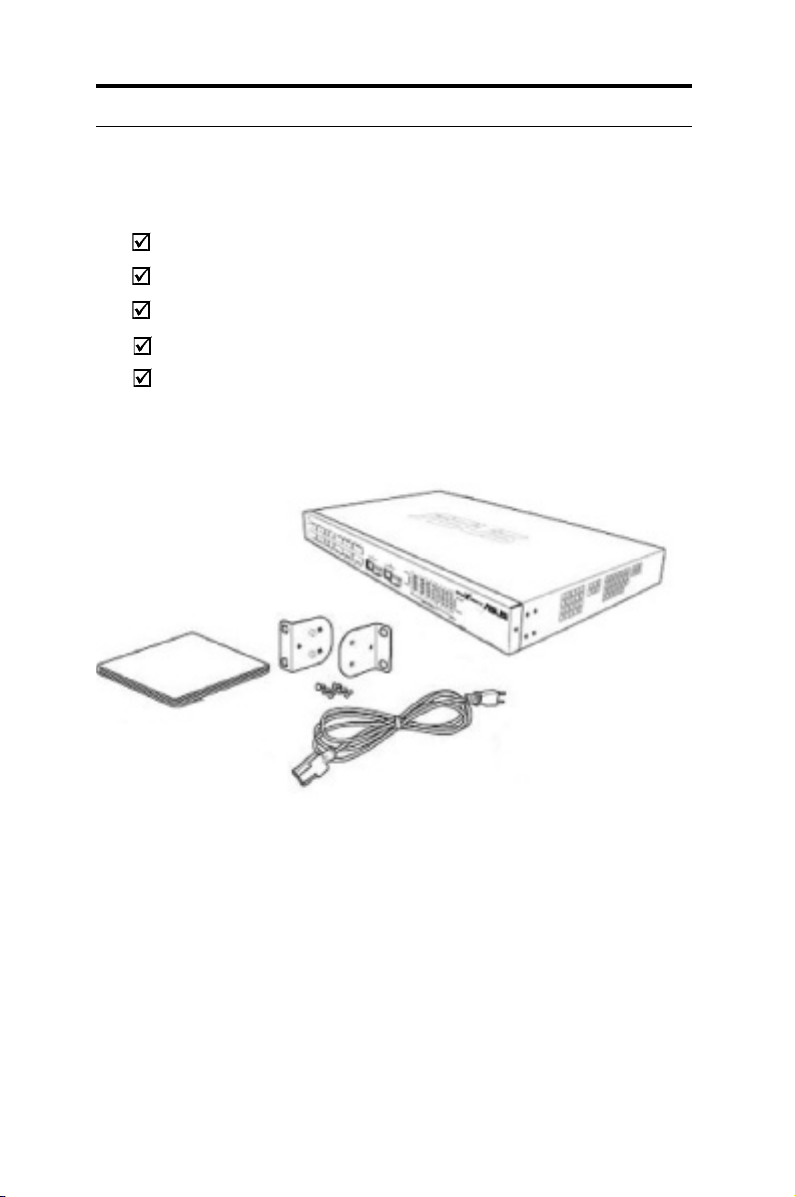
1.2 Package contents
Check the following items in your ASUS GigaX 1024i+ switch package. Contact your
retailer if any item is damaged or missing.
GigaX 1024i+ (28-port) L2 smart plus switch
AC power cord
Rack installation kit (two brackets with six #6-32 screws)
User Manual
Quick installation guide
Figure 1. GigaX L2 smart plus switch package contents
Page 12

3
Chapter 1 - Introduction
ASUS GigaX 1024i+
1.3 Features
• 24 10/100 BASE-TX auto-sensing Fast Ethernet ports
• Two 10/100/1000BASE-T auto-sensing Gigabit Ethernet switching port
• Two small form factor (SFP) Gigabit interface converter (GBIC) slots
• 802.1D/802.1 w transp arent br idge/spanning tree protocol/rapid
spanning tree protocol
• 8K MAC address cache with hardware-assisted aging
• 802.3x ow control
• 802.1Q-based tagged VLAN, up to 256 VLANs
• Port based VLAN
• Private VLAN
• 802.1p class of service, 4 queues per port
• IGMP snooping (v1/v2) support
• Static multicast group support
• 802.3ad link aggregation (manual and LACP), up to 15 trunk groups
• Port Mirroring
• 802.1X port-based network access control
• RADIUS remote authentication dial-in user service
• Ingress and egress bandwidth control
• Port security
• Ethernet cable diagnosis
• DHCP client
• Quality of service classification: DA/SA MAC priority, VLAN priority,
IPv4 ToS/DiffServ, IPv6 Trafc Class
• RMON: support 4 groups (1, 2, 3, 9)
• SNMP v1, v2, v3
• MIB-II
• Enterprise MIB for system rmware version
• FTP for rmware update and conguration backup
• Syslog.
• Web GUI
• LEDs for port link status
• LEDs system status
Page 13
4
Chapter 1 - Introduction
ASUS GigaX 1024i+
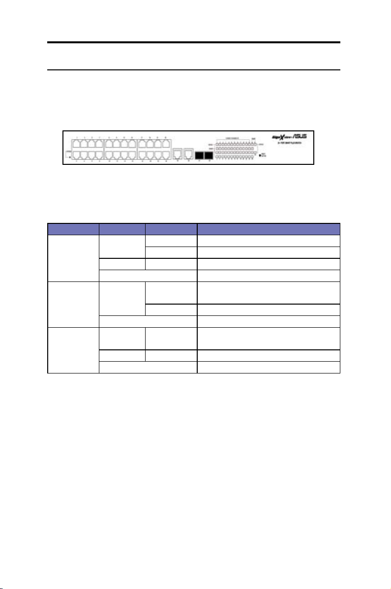
1.4 Front panel features
The front panel includes LED indicators which show the system, and port status.
Figure 2. Front panel
Table 1: Front panel labels and LEDs
Label Color Status Description
SYSTEM Green On Unit is powered on
Flashing Self-test, INIT, or downloading
Amber On Abnormal temperature or voltage
Off No power
10/100/100 0
port status
Green On Link (RJ-45 or SFP) is present; port is
enabled
Flashing Data is being transmitted/received
Off No Ethernet link.
10/100/100 0
port speed
Green On 1000Mbps on Giga port, or 100Mbps on
10/100 ports
Amber On 100Mbps on Giga port
Off 10Mbps or link is not present
Page 14
5
Chapter 1 - Introduction
ASUS GigaX 1024i+
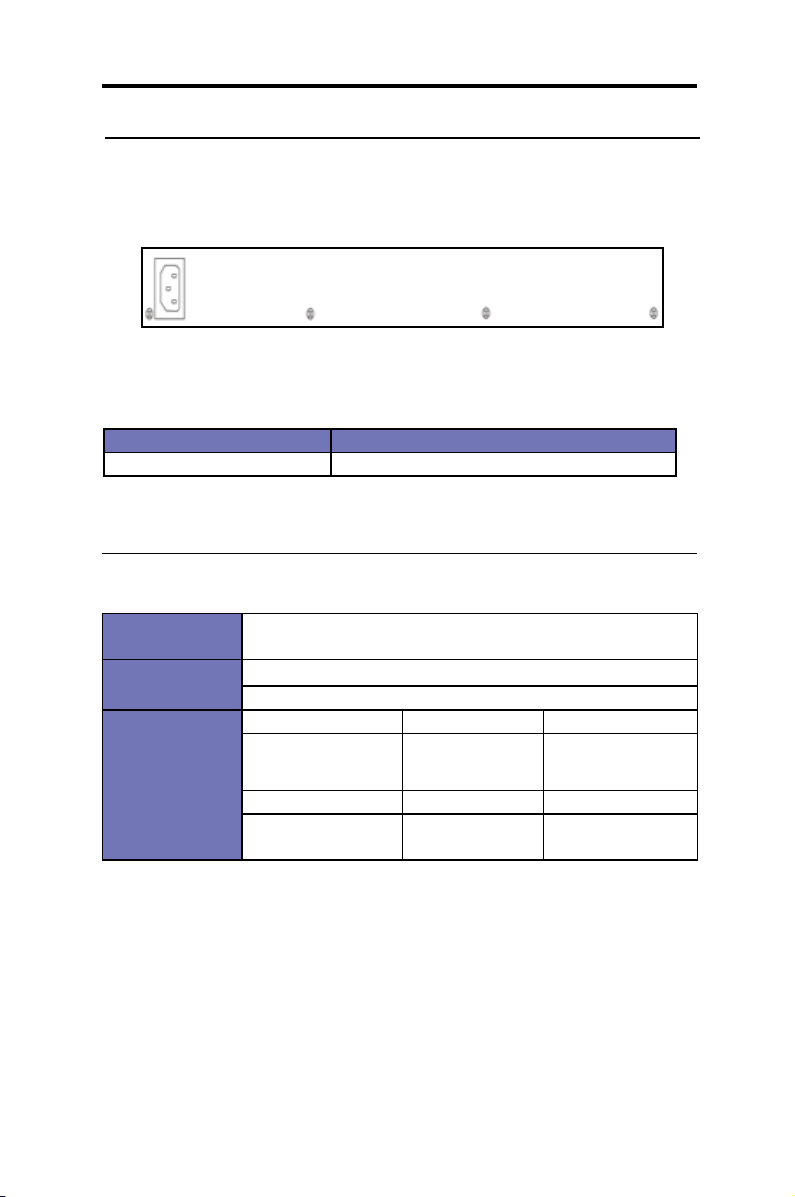
1.5 Rear panel features
The switch rear panel contains the ports for data and power connections.
Figure 3. Rear panel
Table 2: Rear panel labels
Label Description
Power connector Connects to the supplied power cord
1.6 Technical specications
Table 3: Technical specications
Physical
Dimensions
43.5mm(H) X 444 mm(W) X 180mm(D)
Power
Input: 100-240V AC/2A 50-60Hz
Consumption: <50 watts
Environmental
Ranges
Operating Storage
Temperature 0 to 4 0oC (32 to
104oC)
-25 - 70oC
(-13 to 158oC)
Humidity 5 to 90% 0 to 95%
Altitude up to 10,000
ft (3,000m)
40,000 ft (12,000m)
Page 15

6
Chapter 2 - Quick Start
ASUS GigaX 1024i+
2 Quick Start
This section provides the basic instructions to set up the GigaX 1024i+
environment. Refer also to the GigaX 1024i Installation Guide.
• Part 1 shows you how to install the GigaX 1024i+ on a at surface
or on a rack.
• Part 2 provides instructions to set up the hardware.
• Part 3 shows you how to congure the basic settings on the GigaX
1024i+.
Before starting, obtain the following information from your net work
administrator:
• IP address for the switch
• Default gateway for the network
• Network mask for this network
2.1 Part 1: Installing the switch
The switch can be installed either on a at surface or on a rack.
2.1.1 Installing on a at surface
The switch should be installed on a flat surface which can support the
weight of the switches and their accessories. Attach four rubber pads on
the four indented circles located at the bottom of the switch. See illustration
below.
1
2
3
4
Indented circles 1, 2, 3, & 4.
Attach rubber pads here.
Page 16
7
Chapter 2 - Quick Start
ASUS GigaX 1024i+
2.1.2 Installing on a rack
1. With the front panel facing out, insert the switch between the rack posts
and align the four mounting holes with that in the equipment rack.
2. Securely fasten the switch to the rack with two screws on each side.
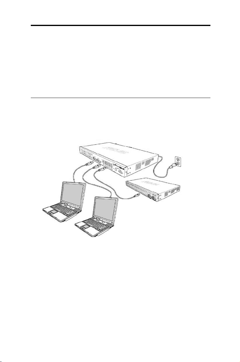
2.2 Part 2: Connecting the hardware
In Part 2, you connect the device to the power outlet, and to your
computer and to your network. Refer to Figure 4 for the overview of the
hardware connections.
CAT 5 Ethernet cables
LAN computers
Expansion hubs/switch
Figure 4. Overview of hardware connections
Page 17

8
Chapter 2 - Quick Start
ASUS GigaX 1024i+
2.2.1 Connect to the computers or a LAN
You can use Ethernet cable to connect computers directly to the switch
ports. You can also connect hubs/switches to the switch ports by Ethernet
cables. You can use either the crossover or straight-through Ethernet cable
to connect computers, hubs, or switches.
Use a twisted-pair Category 5 Ethernet cable to connect the 1000BASE-T
port. Otherwise, the link speed cannot reach 1Gbps.
2.2.2 Attach the power adapter
1. Connect the AC power cord to the POWER receptacle located at the
back of the switch. Plug the other end of the power cord into a wall
outlet or a power strip.
2. Check the front LED indicators. If the LEDs light up as described in
Table 4, the switch is working properly.
Table 4: LED indicators
No LED Description
1 System Solid green indicates that the device is turned on. If
this light is off, check if the power adapter is attached
to the switch and plugged into a power source.
2 Switch ports
[1] to [28]
Solid green indicates that the device can communi-
cate with the LAN. If the light is ashing, it indicates
that the device is sending or receiving data from
your LAN computer.
Page 18
9
Chapter 2 - Quick Start
ASUS GigaX 1024i+
2.3 Part 3: Basic switch settings
After completing the hardware setup, congure the basic settings for your
switch. You can manage the switch either through the:
• Conguration Manager: The switch has a preinstalled web
application to allow you to manage the switch using Java®-enabled
IE5.0 or higher versions. Refer to Chapters 3 & 4 for more information.
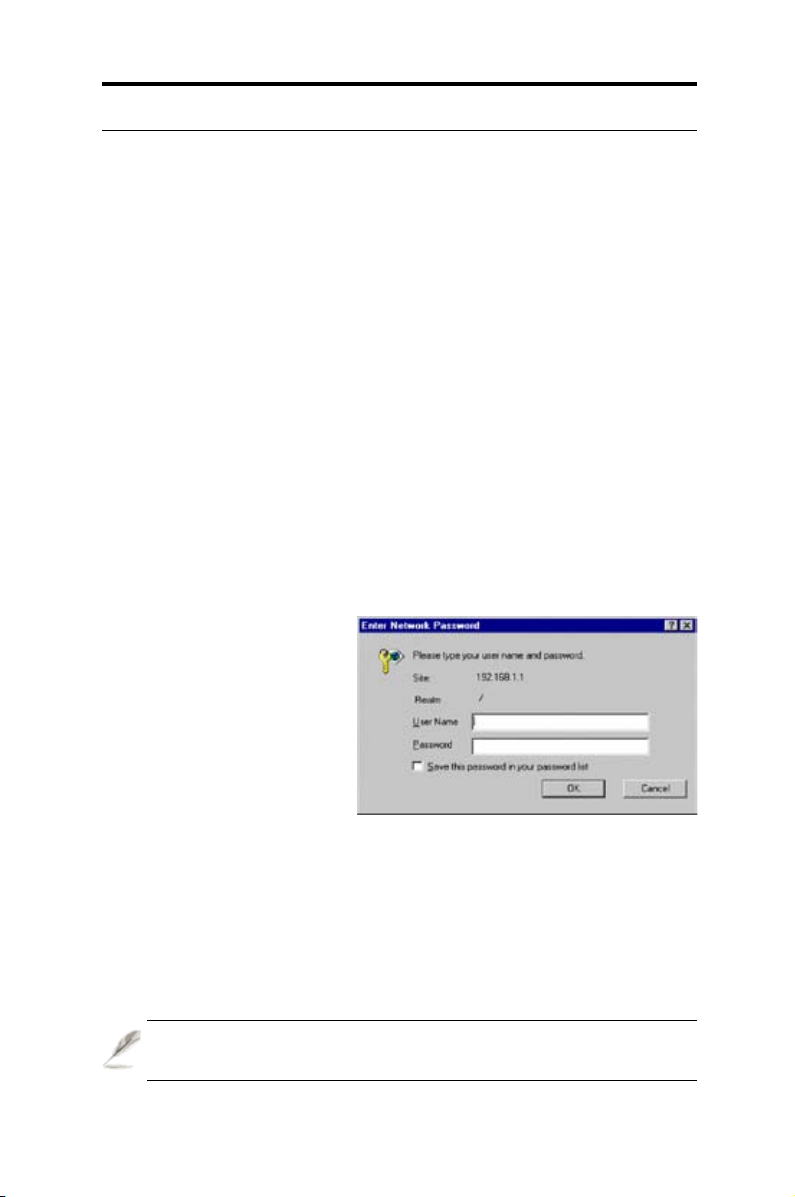
2.3.1 Setting up thru the Conguration Manager
You can mana ge the switch th rough its prein stalled we b s oftware
application called the
Conguration Manager
.
You can access the Configuration Manager through any web browser
(Microsoft Internet Explorer® 5.0 or later versions. Netscape is not
supported.) from any computer connected to the switch via the LAN ports.
1. By default, the switch's web authentication is disabled. You have
to enable it to be able to manage the switch via the Configuration
Manager. You can enable the web authentication function in the
System --> Administration
page.
2. In a web b row ser ( IE
5.0 o r late r ver sio ns),
ent er th i s IP ad dre ss:
htt p:/ /19 2.1 68. 1.1 a nd
pr ess <
En ter
>. This is
the swi tch's d ef aul t IP
address.
A login screen appears as
shown in Figure 5.
3. Enter your username and password, and click <OK>. When logging in
for the rst time, use the following default settings:
Username
: admin
Password
: (no password)
You can change the password at any time.
Figure 5. Login screen
Page 19

10
Chapter 2 - Quick Start
ASUS GigaX 1024i+
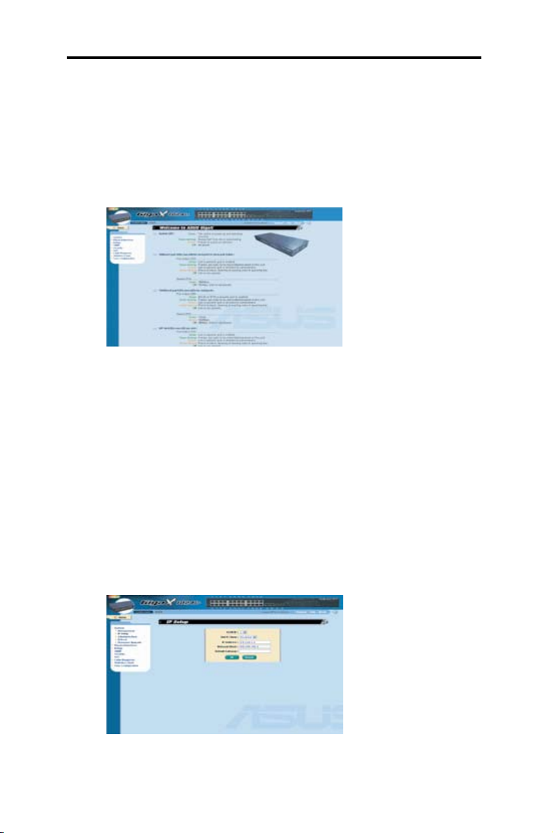
4 . To se t u p a new I P
addre ss, cli ck
Syste m
--> IP Setup
. Fill in the
IP address, the network
mas k, an d the de fau lt
gateway, then click <OK>.
5. If your new addre ss is
different from the default,
t h e b r o w s e r c a n n o t
update the switch status
window or retrieve any page. This is normal. You have to retype the
new IP address in the address/location box and press <
Enter
>. The
web link returns.
6. To enable authentication for web access, click the
Administration
page, then select <
Enabled
>.
Figure 6. IP setup
Page 20

11
Chapter 3 - Using the Conguration Manager
ASUS GigaX 1024i+
3 Using the Conguration Manager
The switch provides a preinstalled web software application called the
Conguration Manager
. It enables you to congure the device settings
to meet the needs of your network. You can access it through your web
browser from any PC connected to the switch via the LAN ports.
3.1 Login to the Conguration Manager
The Configuration Manager is preinstalled on the switch. To access the
application, you need the following:
• A computer connected to the LAN port on the switch as described in
the Quick Start Guide chapter.
• A web browser installed on the computer. The application is designed
to work best with Microsoft Internet Explorer® 5.0 or later versions. It
does not support Netscape.
You may access the program from any computer connected to the switch
via the LAN ports.
3.1.1 Setting up the Conguration Manager
1. By default, the switch's web authentication is disabled. You have
to enable it to be able to manage the switch via the Configuration
Manager. You can enable the web’s authentication function in the
System --> Administration
page.
2.In a web browser, enter this IP address:
http://192.168.1.1
and
press <
Enter
>. This is the switch's default IP address. A login screen
appears.
Figure 7. Cong manager login screen
Page 21
12
Chapter 3 - Using the Conguration Manager
ASUS GigaX 1024i+
3. Enter your username and password, and then click <OK> to enter
the Conguration Manager. When logging in for the rst time, use the
following default settings:
Username: admin
Password
: (no password)
The home page appears at every log in to the system.
Figure 9. IP setup
Figure 8. Home page
3.1.2 Setting up a new IP address
1. To set up a new IP address, click System --> IP Setup. Fill in the
IP address, the network mask and the default gateway, then click
<OK>. The IP setup screen appears after you click <OK>.
2. If your new address is different from the default, the browser can not
update the switch status window or retrieve any page. This is normal.
You have to retype the new IP address in the address/location box,
and press <Enter>. This will refresh your web page.
3. To enable authentication for Web access, click Administration on the
menu list, then select Enabled to start the password protection.
Page 22

13
Chapter 3 - Using the Conguration Manager
ASUS GigaX 1024i+
3.2 Functional layout
A typical web page consists of three frames: the top, left, and right frames.
Port Color Description
Green Ethernet link is established
Black No Ethernet link
Amber Link is present but port is disabled manually or by spanning tree
Table 5: Port color description
The
top frame
(or the banner frame) contains the switch's logo and the
front panel. It shows periodic updates of the LED status. See the following
for LED information:
• Table 4 for the LED denitions (on page 8).
• Table 5 for the color status description.
Clicking on the port icon of the switch displays the port conguration in the
lower right frame.
Top frame
Left frame
Right frame
Figure 10. Functional layout
Page 23

14
Chapter 3 - Using the Conguration Manager
ASUS GigaX 1024i+
Button / Icon Function
Stores any changes made on the current page.
Adds the existing conguration to the system, e.g., a static
MAC address or a rewall ACL rule, etc.
Modies an existing entry.
Deletes the selected item, e.g. a static route or a lter ACL
rule and etc.
Re-displays the current page with updated statistics or
settings.
Table 5: Commonly used buttons and buttons
The
left frame
contains the menu bar containing all
the features available for switch configuration. These
features are grouped into categories, e.g. System,
Bridge, etc. You can click on any of these to display a
specic conguration page.
The
right frame
di splays config uration pages or
graphics for the statistics. See Chapter 4.8 for details.
3.2.1 Menu navigation tips
• To expand a group of related menus, double-click the
icon:
• To contract a group of related menus, double-click the
icon:
Figure 11. Expanded
menu list.
3.2.2 Commonly used buttons and icons
Refer to the table for the function of each button and icon used in the
application.
Page 24

15
Chapter 4 - Conguration Management
ASUS GigaX 1024i+
4 Conguration Management
This chapter describes the features you can use in the Configuration
Manager, the switch's preinstalled software application. These features
are:
• System
• Physical Interface
• Bridge
• SNMP
• Security
• Cable Diagnosis
• Statistical Chart
• Save Conguration
To permanently save the changes or new settings made on any of
the switch’s features (or conguration), you must go to the Save
Conguration page, and click on <Save>.
4.1 System
This section describes the tasks you can perform using the
System
feature in the Conguration Manager:
• Conguring the system name, contact, location, & other system info;
• Assigning IP addresses;
• Enabling / disabling web authentication;
• Rebooting the system; and
• Updating the rmware.
Page 25

16
Chapter 4 - Conguration Management
ASUS GigaX 1024i+
4.1.1 Management
The
Management
page contains
the following information:
•
Model Name
: The product's name.
•
MAC Address
: The switch's MAC
address.
•
Sys t em Na m e
: The na me to
identify the system (editable).
•
System Contact
: The system's
contact (editable).
•
System Location
: The location of the system (editable).
To save any changes you have made, click <OK>. Use <
Reload
> to
refresh the settings.
4.1.2 IP Setup
The switch supports dynamic IP and static IP assignment. The dynamic IP
is obtained from a DHCP server within the same VLAN. The IP Setup page
contains the following editable parameters:
• VLAN ID: Specify a VLAN ID to system management interface. It is
necessary that it should be within the same VLAN for management uses.
• DHCP Client: Enable DHCP to get a dynamic IP address, or disable
DHCP to specify a static IP address. The DHCP server must be
reachable within the management VLAN.
• IP Address: assign a static IP address to the switch management
interface.
• Network Mask
• Default Gateway
To save any changes made, click <OK>. Use <
Reload
> to refresh the
settings.
4.1.3 Administration
The
Administration
page allows you enable or disable the authentication
for a web user, or add/ modify / remove a user in the user database. You
Figure 12. Management
Page 26

17
Chapter 4 - Conguration Management
ASUS GigaX 1024i+
can set up to 8 users. The default settings for web access does not require
any authentication.
•
P a s s w o r d Pr o t e c t i o n is
:
Ena b le o r D isa b le the web
authentication.
•
User Name
: New user name.
•
Password
: Password for the new
user.
•
Confirm Password
: Enter the
password again for conrmation.
Click on <
Add
> to add the new user. Click on <
Modify
> when you are
done with the modications. Click on <
Remove
> when you want to remove
the selected user.
To save any changes made, click<OK>. Use <
Reload
> to refresh the
settings. When you enable the password protection, you have to login
again immediately.
4.1.4 Reboot
To reboot the system:
1. Click on
System --> Reboot
. The Reboot page will be displayed.
2. Click on <
Reboot
>.
Rebooting the system stops the network traffic and terminates the
Internet connection.
Figure 13. Administration
Figure 14. Reboot
Page 27

18
Chapter 4 - Conguration Management
ASUS GigaX 1024i+
4.1.5 Firmware Upgrade
From time to time, ASUS will provide
you with an update to the firmware
running on the GigaX L2 Managed
Swi t ch. A l l s yste m s o ftwa r e i s
contained in a single file called an
image. The Configuration Manager
provides an easy way to upload the
new rmware image.
To upgrade the rmware:
1. Click on
System --> Firmware Upgrade
to open the Firmware page.
The Firmware page contains the following information:
•
Hardware Version
: shows the hardware revision number.
•
Boot ROM Version
: shows the version of the boot code.
•
Firmware Version
: shows the current running rmware version.
This number will be updated after the rmware update.
2. In the
Firmware or Auto-config file
text box, enter the path and
name of the rmware image le. You may also click on <
Browse
> to
search for the rmware image on your PC.
3. Click on <
Upload
> to update the rmware, and automatically reboots
the system.
If automatic rebooting does not take place, refer to section 4.1.4:
Reboot for steps on rebooting the system.
The lename of the auto-cong le must be “cong.bat”, and the rst
line of the le must be “#autocong”.
Figure 15. Firmware upgrade
Page 28

19
Chapter 4 - Conguration Management
ASUS GigaX 1024i+
4.2 Physical Interface
The Physical Interface displays the
Ethernet port status in real time.
You can configure the port in the
following elds:
•
Port
: select the port to congure
•
Admin
: disable/enable the port
•
Mode
: set the speed and duplex
mode
•
Flow Control
: enable/disable 802.3x ow control mechanism
•
Port Status Window
: displays the following information for each port:
Link Status the link speed and duplex for an existing
link, otherwise link is down
State the STP state
Admin the setting value to disable or enable the port
Mode the setting value to enable or disable
802.3x ow control mechanism
Flow Control the setting value to enable or disable
802.3x ow control mechanism
To modify this page, select the corresponding port number and congure
the port setting, then click <
Modify
>. The eld you change will update the
content of the display window. However, the new settings do not take effect
until the
Save Conguration
(refer to Chapter 4.9: Save Conguration) is
executed.
Figure 16. Physical Interface
Page 29

20
Chapter 4 - Conguration Management
ASUS GigaX 1024i+
4.3 Bridge
The Bridge page group contains most layer 2 congurations such as the
link aggregation, the STP, etc.
4.3.1 Spanning Tree
The c o nfi gur ati o n pag e f or th e
Spanning Tree Protocol (STP) can
disable and enable the feature in
runtime. This page consists of three
parts:
a) The root information;
b) The STP setting; and
c) The port setting.
The root information
The rst part shows the root information. It tells the user the root switch's
STP setting.
The STP Setting
The second part is the STP setting. The following options are available:
•
Disable/STP Enable/RSTP Enabled
: Turn the STP/RSTP off/on. When
you turn the STP/RSTP on, STP/RSTP will use the following settings if the
switch is the root switch.
•
Hello Time
: The interval between the generation of conguration BPDU
•
Max Age
: A timeout value to be used by all Bridges in the LAN
•
Forward Delay
: A timeout value to be used by all bridges in the LAN
•
Bridge Priority
: The switch priority in the LAN
The Port Setting
The third part is the port setting. It contains a display window showing each
port's current conguration. Click <
Modify
> to change the port setting for
STP/RSTP. The following elds are available:
•
Port
: Select the corresponding port to congure
Figure 17. Spanning Tree
Page 30

21
Chapter 4 - Conguration Management
ASUS GigaX 1024i+
•
Priority
: The port priority in the switch. Low numeric value indicates a
high priority. The port with lower priority is more likely to be blocked by
STP if a network loop is detected. The valid value is from 0 to 240.
•
Path Cost
: The valid value is from 1 to 200000000 or Auto. The path cost
of the user conguration is displayed in the AdminCost, and the operation
path cost is displayed in the OperCost. The higher cost is more likely to be
blocked by STP if a network loop is detected.
•
Edge Port
: All ports are set to be edge ports by default. Edge port
becomes STP port when BPDU is received. Also, it takes a very short time
for an edge port to be in forwarding state.
•
Point to Point: Auto/Yes/No
: A full duplex link is considered as a point
to point link. Otherwise, it is a shared link. Point to point link may have less
convergence time. Auto is recommended in most cases.
Click <OK> to save any changes made to the settings. Click <
Reload
> to
refresh the settings.
4.3.2 Link Aggregation
This p a ge c o n figure s the link
aggregation group (port trunking).
T h e s w i t c h c a n hav e 15 li nk
agg rega tio n g rou ps. It h as the
following conguration parameters:
•
Show Trunk
: Select
Add a new
Trunk
to create a new group. Or
select an existing group to display on
the following elds and port icons.
•
Name
: The group name.
•
Trunk ID
: A number to identify the trunk group besides the group name.
•
LACP
: Enable/Disable LCAP on selected trunk. LACP mode is xed to
be Active.
•
Remove Trunk
: Remove the selected trunk.
•
Port Icons
: These port icons are listed in a way like the front panel. You
have to click on the icon the select the group members. The port can be
removed from the group by clicking the selected port again.
Click <OK> to send the settings to the switch via the HTTP server.
Click <
Reload
> to refresh the settings. To permanently save the new
conguration, go to the
Save Conguration
page, then click <
Save
>.
Figure 18. Link aggregation
Page 31

22
Chapter 4 - Conguration Management
ASUS GigaX 1024i+
You have to check the runtime link speed and the duplex mode to make
sure the trunk is physically active. Go to
Physical Interface
and check
the link mode in the runtime status window for the trunk ports. If all the
trunk members are in the same speed and full duplex mode, then the trunk
group is set up successfully. If one of the members is not in the same
speed or full duplex mode, the trunk is not set correctly. Check the link
partner and change the settings to have the same speed and full duplex
mode for all the members of your trunk group.
4.3.3 Mirroring
Mirroring
, together with a network
traffic analyzer, helps you monitor
the network trafcs. You can monitor
th e select ed ports for eg re ss or
ingress packets.
•
Mirror Mode
: Enables or disables
the mirror function for the selected
group.
•
Monitor Port
: Receives the copies
of all the trafcs in the selected mirrored ports.
All the ports in the link aggregation group MUST operate in full-duplex
mode at the same speed.
All the ports in the link aggregation group MUST be congured in autonegotiation mode or full duplex mode. This conguration will make the
full duplex link possible. If you set the ports in full duplex force mode,
then the link partner MUST have the same setting. Otherwise the link
aggregation could operate abnormally.
All the ports in the link aggregation group MUST have the same VLAN
setting.
All the ports in the link aggregation group are treated as a single logical
link. That is, if any member changes an attribute, the others will change
too. For example, a trunk group consists of port 1 and 2. If the VLAN of
port 1 changes, the VLAN of port 2 also changes with port 1.
Figure 19. Mirroring page
Page 32

23
Chapter 4 - Conguration Management
ASUS GigaX 1024i+
The monitor port can not belong to any link aggregation group.
T h e m o n i t o r p o r t c an n ot op e ra t e as a no r ma l sw i tc h
por t . I t do e s n o t s w itc h pa c ket s or do a ddr e ss l ear n ing .
Only supports 8 egress ports to be mirrored, and the monitored
egress packets will be untag.
Click <OK> to send the new settings to the switch via the HTTP server.
Click to <
Reload
> to refresh the settings.
4.3.4 Static Multicast
T h i s page c a n a d d mult i c a s t
addresses into the multicast table.
The s wit ch ca n hol d up to 1 27
multicast entries. A ll the ports in
the group will forward the specified
multicast packets to other ports in
the group.
•
Show Group
: Select
Add a new
Group
to enter a new entry, or select
an existing group address to display.
•
MAC Address
: Selects the multicast address
•
VLAN
: Selects the vlan group
Click <OK> to save any changes made. Click <
Reload
> to refresh the
settings.
4.3.5 IGMP Snooping
The IGMP snooping function can be
turned on or off. This helps reduce
the multicast trafcs on the network.
When turned on, the switch snoops
the IGMP packets and puts the new
group into the multicast table. However, if the static entries occupy all
256 spaces, the IGMP snoop does
not work normally. The switch only
allows 256-layer 2 multicast group.
Figure 20. Static multicast
Figure 21. IGMP Snooping
Page 33

24
Chapter 4 - Conguration Management
ASUS GigaX 1024i+
4.3.6 Bandwidth Control
B a n d w i d t h c o n t r ol l i m i t s t h e
trans m i s sion rate of s e lecte d
frames. The swi tch supports this
on a per port basis by setting the
conguration in the following elds:
Ingress bandwidth control
•
Port
: Select the port to congure.
•
Co ntrol
: Disable/ en able t he
ingress bandwidth control.
•
Mode
:
•
Bcast
: Limit the broadcast packets.
•
Bcast, Mcast
: Limit the broadcast and multicast packets.
•
Bcast, Mcast, Dlf
: Limit the broadcast packets, multicast
packets and unicast packets because of destination address
lookup failure.
•
All
: Limit all types of packets.
•
Limit Rate
: The threshold to limit the total number of the selected
type of packet. For example, if broadcast/multicast is enabled, the
trafc amount of each type will not exceed the limit value. The valid
value is from 70 to 250000(Kbps).
Egress bandwidth control
•
Port
: Select the port to congure.
•
Bandwidth Control
: Disable/enable the bandwidth control.
•
Limit Rate
: Maximum egress transmission rate. The valid value is from
70 to 250000(Kbps).
Click <OK> to send the settings to the switch via the HTTP server. Click
<
Reload
> to refresh the settings. To permanently save the conguration,
go to the
Save Conguration
page, then click <
Save
>.
Figure 22. Bandwidth Control
Page 34

25
Chapter 4 - Conguration Management
ASUS GigaX 1024i+
4.3.7 Dynamic Addresses
This page displays the result of the
dynamic MAC address lookup by
port, VLAN ID, or MAC address. The
dynamic address, which is the MAC
ad dr es s spe ci fi ed in the lo ok up ,
will expire based on the configured
"aging time". You can enter a valid
number from 15 to 3825 (in seconds)
to congure the expiry time (or aging
time). To save any changes made to
this page, click <OK>. To permanently save the new conguration, go to
the
Save Conguration
page and click <
Save
>.
To lookup for MAC addresses, you can check the port, VLAN ID, or MAC
address, and then click on <
Query
>. The address window will display the
results.
4.3.8 Static Addresses
MAC addresses entered in this page
will not expire, and will remain static
in the address table until you remove
it from the address list.
The
Static Addresses
page has the
following parameters:
•
MAC Address
: Enter the MAC
address
•
VLAN ID
: Enter the VLAN ID that
the MAC belongs to
•
Port Selection
: Select the port which the MAC belongs to
•
Discard on
: You can do packet filtering when the MAC address
appears in the packets as destination address.
To create a new static MAC address
Click on <Add>. The new entry will be displayed on the address window.
Up to 15 entries will be displayed in the rst address window, and the other
entries will be displayed in the succeeding pages. Click on First, Previous, Next, and Last links to navigate through the entries' list.
Figure 23. Dynamic Address
Figure 24. Static Address
Page 35

26
Chapter 4 - Conguration Management
ASUS GigaX 1024i+
To modify a MAC address
Select the MAC address you want to modify, then click on <Modify>.
To remove a MAC address
Select the MAC address you want to remove, then click <Remove>.
To query a MAC address
Enter the MAC address and the VLAN ID, then click <
Query
>. Your
query will be displayed in the address window.
To save the changes you have made on this page, click <OK>. Click
<
Re load
> to re fresh the se ttings. To per manentl y save the ne w
conguration, go to the
Save Conguration
page, then click <
Save
>.
4.3.9 VLAN
4.3.9.1 VLAN Mode
There are two VLAN modes in our
switch: (1) Port-Based VLAN, (2)
802.1Q Tagged VLAN. The switch
supports this on a per port basis
by setting the configuration in the
following elds:
a)
Port
: Select the port to congure.
b)
VLAN Mode
•
802.1Q Tagged VLAN
: Forwarding decision follows the 802.1Q Tagged
VLAN.
•
Port-Based VLAN
: if a port is in Port-Based VLAN mode: 1) when
the port receives a tagged packet, the forwarding decision follows the
802.1Q Tagged VLAN; and 2) when it receives an untagged packet,
the forwarding decision follows the Port-Based VLAN.
Restrictions
• If a port is in Port-Based VLAN Mode, it cannot be a promiscuous port,
and cannot run 802.1x and IGMP snooping.
• Trunked members must in the same VLAN mode.
Figure 25. VLAN mode
Page 36

27
Chapter 4 - Conguration Management
ASUS GigaX 1024i+
Click <OK> to send the settings to the switch via the HTTP server. Click
<
Reload
> to refresh the settings. To save the conguration, go to the
Save
Conguration
page, then click <
Save
>.
4.3.9.2 Tagged VLAN
You can set up to 227 VLAN groups
and show VLAN group in this page.
There is a default VLAN created by
the switch. This feature prevents the
switch from malfunctions. You can
remove any existing VLAN except
the default VLAN.
You can assign the port to be either
a tagged port or an untagged port by
toggling the port button. There are
three types of button:
•
“U” type
: Untagged port, which will remov e VLAN tags from the
transmitted packets.
•
“T” type
: All packets transmitted from this port will be tagged.
•
“blank” type
: This port is not a member of the VLAN group.
The other elds that you can congure are as follows:
•
Show VLAN
: Select the existing VLAN to display or select
Add a new
VLAN
to create a new VLAN group.
•
Name
: the VLAN name.
•
VLAN ID
: This field requires user to enter the VLAN ID when a new
VLAN is created.
•
Remove VLAN
: Remove an existing VLAN. This field disappears in
VLAN creation page.
•
Private VLAN
: Set this VLAN to be a Private VLAN(PVLAN). PVLAN
is to provide LAN security with the simplicity of VLAN conguration. The
system administrator can reduce the VLAN and IP consumption but
provide the same security to LAN. We cannot use default VLAN (VLAN 1)
as the PVLAN. In our system, the total number of PVLAN is four. Mirrorto port cannot be a PVLAN member. Static Multicast cannot be a PVLAN.
There are two port types in a PVLAN: 1) Promiscuous Port and 2) Isolated
Port.
a)
Promiscuous Port
: A PVLAN must and only can have one promiscuous
Figure 26. Tagged VLAN
Page 37

28
Chapter 4 - Conguration Management
ASUS GigaX 1024i+
port. It communicates with all interfaces within a PVLAN. Some restrictions
in a promiscuous port are as follows:
• Promiscuous port must be an untagged port.
• Trunked port cannot be a promiscuous port.
• Promiscuous port cannot be in Port-Based VLAN Mode.
b)
Isolated Port
: The non-promiscuous port in a PVLAN. It has complete
Layer 2 separation from the other ports within the same PVLAN, but not
from the promiscuous port. PVLANs block all trafc to isolated ports except
trafc from promiscuous port. Trafc from isolated port is forwarded only
to promiscuous port. Trafc control does not work for isolated port. Some
restrictions in an isolated port are as follows:
• Isolated port only process untagged packets. If isolated port
receives tagged packets, they will be dropped.
• Isolated port only can belong to one VLAN, and the VLAN is a
Private VLAN.
• Isolated port cannot run IGMP snooping.
•
Priority Override
: When priority override is checked, the priority override
based on the VLAN ID can only occur on the members of this VLAN.
When this occurs, the priority eld of any packets with this VLAN ID will be
overridden with the priority value. The VLAN priority override has higher
priority than the port’s default priority, and IP priority.
•
Priority
: The priority value is used to override the priority on any frames
associated with this VLAN ID, if priority override is checked.
If you want the VLAN members’ forwarding decision to follow the 802.1Q
Tagged VLAN, you must go to the
VLAN Mode
page and select “
802.1Q
Tagged VLAN
” mode as the VLAN Mode of these port members.
Click <OK> to send the settings to the switch via the HTTP server. Click
<
Reload
> to refresh the settings. To permanently save the conguration,
please go to the
Save Conguration
page, then click <
Save
>.
4.3.9.3 Port-Based VLAN
Port-Based VLAN
is VLAN where the packet forwarding decision is based
on the destination MAC address and its associated port. It is the simplest
and most common form of VLAN. In a Port-Based VLAN, the system
administrator assigns the switch’s ports to a specic VLAN group. You can
set up to 28 Port-Based VLAN groups and show VLAN group in this page.
Page 38

29
Chapter 4 - Conguration Management
ASUS GigaX 1024i+
•
Show Port-Based VLAN
: Select
Add a new VLAN
to create a new
group, or select an existing group to
display on the following fields and
port icons:
•
Name
: the group name.
•
Group ID
: this eld requires you to
enter the Group ID when a new PortBased VLAN is created. The valid
Group ID is from 1 to 28.
•
Remove Group
: Remove an existing Port-Based VLAN Group. This eld
disappears in Port-Based VLAN Group creation page.
If you want the Port-Based VLAN group that you created to be effective,
you must go to
VLAN Mode
page to select
Port-Based VLAN
mode as
the VLAN Mode of these port members.
Click <OK> to send the settings to the switch via the HTTP server. Click
<
Reload
> to refresh the settings. To permanently save the conguration,
go to the
Save Conguration
page, then click <
Save
>.
4.3.10 Default Port VLAN and CoS
Th is page inc lu de s some VLAN
tags' related field settings for each
port. These are as follows:
•
Port
: Select the port to congure
•
PVID
: Port-based VLAN ID. Every
untagged packet received from this
port will be tagged with this VLAN
group ID
•
CoS (Class of Service) value
:
Every untagged packet received from this port will be assigned to this CoS
in the VLAN tagged.
Click <
Modify
> to change the content in the port list window. Click <OK>
to send the settings the switch via the HTTP server. Click <
Reload
> to
refresh the settings. To permanently save the conguration, go to the
Save
Conguration
page, then click <
Save
>.
Figure 27. Port-Based VLAN
Figure 28. Default Port VLAN & CoS
Page 39

30
Chapter 4 - Conguration Management
ASUS GigaX 1024i+
4.4 SNMP
Simple Network Management Protocol (SNMP)
is used to manage the
network. You may use the SNMP conguration page to enable or disable
the SNMP support.
To provide more secure management and access control, SNMPv3 is
supported. SNMP has the following conguration parameters:
4.4.1 Community Table
You can enter different community
names and specify a write-access
priv i leg e to t h e c ommu n ity by
check i n g t h e ch e c k box. Clic k
<OK> to save the configuration or
<
Reload
> to refresh the page.
4.4.2 Host Table
This page links the host IP address
to th e comm uni ty na me tha t i s
entered in Community Table page.
Type an IP address and select the
co mm un it y name from th e dropdown list. Click <OK> to save the
conguration or <
Reload
> to refresh
the page.
4.4.3 Trap Setting
By settin g the trap destination IP
addresses and community names,
you can enable SNMP trap function
to send trap packets in different
versions (v1 or v2c). Click <OK> to
save the conguration or <
Reload
>
to refresh the page.
Figure 29. Community Table
Figure 30. Host Table
Figure 31. Trap Setting
Page 40

31
Chapter 4 - Conguration Management
ASUS GigaX 1024i+
4.4.4 VACM Group
VACM (View-based Access Control
Model) Group
is used to configure
the information of SNMPV3 VACM
Group.
The VACM Group pag e ha s th e
following conguration parameters:
•
Group Name
: Enter the security
group name.
•
Read View Name
: Enter the Read
View Name that the Group belongs to. The related SNMP messages are
Get, GetNext, GetBulk.
•
Write View Name
: Enter the Write View Name that the Group belongs to.
The related SNMP message is Set.
•
Notify View Name
: Enter the Notify View Name that the Group belongs
to. The related SNMP messages are Trap, Report.
•
Security Model
: Enter the Security Model Name that the Group belongs
to. Any is suitable for v1,v2,v3. USM is SNMPv3 related.
•
Security level
: Enter the Security level Name that the Group belongs to.
Only NoAuth, AuthNopriv, AuthPriv can be chosen.
Click <
Add
> to create a new VACM group. To remove an existing VACM
Group, select the group and click <
Remove
>. To update an existing entry,
select the group and click <
Modify
>. Click <OK> to save the changes on
this page. Click <
Reload
> to refresh the settings. To permanently save the
new conguration, go to the
Save Conguration
page, then click <
Save
>.
4.4.5 VACM View
VAC M ( V i ew- b a s ed Ac c e s s
Control Model) View
is used to view
the information of SNMPV3 VACM
Group.
The VACM View has the following
parameters:
•
View Name
: Enter the security
group name.
•
View Ty pe
: S e l ect t h e V i ew
Type that the View belongs to. Included or Excluded when View Subtree
Figure 32. VACM Group
Figure 33. VACM View
Page 41

32
Chapter 4 - Conguration Management
ASUS GigaX 1024i+
matches the Oid in the SNMPv3 message.
•
View Subtree
: Enter the View Subtree that the View belongs to. The
Subtree is the Oid to match the Oid in the SNMPv3 message. The match
is good when the subtree is shorter than the Oid in the SNMPv3 message.
•
View Mask
: Enter the View Mask that the View belongs to. Each bit in
the mask represents the digit between the dots of View Subtree from left
side. Bit ‘0’ means ‘nothing’.
Click <
Add
> to create a new VACM View entry. To remove an existing
entry, select the view and click <
Remove
>. To update an existing entry,
select the view and click <
Modify
>. Click <OK> to save the changes on
this page. Click <
Reload
> to refresh the settings. To permanently save the
new conguration, go to the
Save Conguration
page, then click <
Save
>.
4.4.6 USM User
USM (User-based Security Model)
User
i s us e d t o co n f igur e th e
information of SNMPV3 USM User.
T h e USM U se r p a g e ha s the
following parameters:
•
Engine Id
: Enter the Engine Id that
matches the ID in the Manager.
•
Name
: Enter Name combined with Engine ID that should match the
Name and Engine ID in the Manager.
•
Auth Protocol
: Enter the Auth Protocol that Engine ID and Name belong
to. Only NoAuth, MD5, SHA1 can be chosen. If the NoAuth is chosen,
there is no need to enter the password.
•
Auth Password
: Enter the password that the Auth Protocol belongs to.
The password needs at least 8 characters or digits.
•
Priv Protocol
: Enter the Priv Protocol that Engine ID and Name belong
to. Only NoPriv ,DES can be chosen. If the NoPriv is chosen, there is no
need to enter password.
•
Priv Password
: Enter the password that the Priv Protocol belongs to.
The password needs at least 8 characters or digits.
Click <
Add
> to create a new USM User entry. To remove an existing
entry, select the entry and click <
Remove
>. To update an existing entry,
select the entry and click <
Modify
>. Click <OK> to save the changes on
this page. Click <
Reload
> to refresh the settings. To permanently save the
new conguration, go to the
Save Conguration
page, then click <
Save
>.
Figure 34. USM User
Page 42

33
Chapter 4 - Conguration Management
ASUS GigaX 1024i+
4.5 Security
The switch has the 802.1x port-based security feature. Only authorized
hosts are allowe d t o access th e switch po rt. Traffic is blocked for
unauthorized hosts. The authentication service is provided by a RADIUS
server or the local database in the switch.
The switch also supports dynamic VLAN assignment through the 802.1x
authentication process. The VLAN information for the users/ports should
be properly configured in the authentication server before enabling this
feature.
4.5.1 Port Access Control
Po rt Access Control
is used to
congure various 802.1x parameters.
802.1x uses either a RADIUS server
or a local database to authenticate
port users.
Port Access Control has two settings:
the Bridge (Global) settings and the
port settings.
Bridge (Global) settings
The Bridge (Glo bal) setti ngs page has the foll owing conf iguration
parameters:
•
Reauthentication
: Once enabled, the switch will try to authenticate the
port user again when the reauthentication time is up.
•
Reauthentication Time
: If ‘Reauthentication’ is enabled, this is the
interval for the switch to re-send authentication request to the port user.
•
Authentication Method
: RADIUS or Local database can be used to
authenticate the port user.
•
Quiet Period
: If authentication failed either from the RADIUS or the local
database, the switch waits upon this time period before sending another
authentication request to the port user.
•
Retransmission Time
: If the port user failed to respond to authentication
request from the switch, the switch waits upon this time period before
sending another authentication request to the port user.
•
Max Reauthentication Attempts
: Retry count if the port user failed to
respond to authentication requests from the switch.
Figure 35. Port Access Control
Page 43

34
Chapter 4 - Conguration Management
ASUS GigaX 1024i+
Port settings
The port settings page has the following conguration parameters:
•
Port
: Specify which port to be congured.
•
AuthMode (Authentic ation Mode)
: If
Port_based
is selected, it
requires only one host to be authenticated per port by a remote RADIUS
server, a remote TACACS+ server, or a local user database. ‘Port_based’
supports Multi-host and GuestVID. Otherwise, if
MAC_based
is selected,
each host must be authenticated before accessing to the nerwork.
‘MAC_based’ doesn’t support Multi-host and GuestVID. The system
supports up to 256 hosts that try to be authenticated by ‘MAC_based’. If
‘MAC_based’ is selected, enabling the ‘Reauthentication’ in bridge settings
is recommended.
•
AuthCtrl (Authentication Control)
: If
Force_authorized
is selected,
the selected port is forced to be authorized. Thus, traffic from all hosts
is allowed to pass. Otherwise, if
Force_unauthorized
is selected, the
selected port is blocked and no trafc can go through. If ‘Auto’ is selected,
the behavior of the selected port is controlled by the 802.1x protocol.
•
Multi-host
: If enabled, all hosts connected to the selected port are
allowed to use the port if ONE of the hosts passed the authentication. If
disabled, only ONE host among other hosts passed the authentication is
allowed to use the port.
•
GuestVID
: Guest VLAN allows guest users that without 802.1x clients to
have limited network access.
Click <OK> to save the settings. Click <
Reload
> to refresh the settings.
To save the conguration, go to the
Save Conguration
page and click
<
Save
>.
4.5.2 Dial-In User
Dial-in User
is used to dene users
in the local database of the switch.
It has the following configuration
parameters:
•
User Name
: New username.
•
Password
: Password for the new
user.
•
Co nf ir m Pas sw or d
: Ent er the
Figure 36. Dial-In User
Page 44

35
Chapter 4 - Conguration Management
ASUS GigaX 1024i+
password again for conrmation.
•
D y n a mi c V L A N
: S p e c ify t h e V L A N ID ass i g n ed to th e
802.1x-authenticated clients.
Click <
Add
> to create the new user. Click <
Modify
> when want to make
some modifications. Click <
Remove
> when you want to remove the
selected user. Click <OK> to save the settings. Click <
Reload
> to refresh
the settings.
4.5.3 RADIUS
In order to use ex ternal RADIUS
server, the following parameters are
required to be setup:
•
Authentication Server IP
: The IP
address of the RADIUS server.
•
Authentication Server Port
: The
port number that the RADIUS server
is listening to.
•
Authentication Server Key
: The
key is used for communications between the GigaX and the RADIUS
server.
•
Conrm Authentication Key
: Re-type the key for conrmation.
Click <OK> to save the settings. Click <
Reload
> to refresh the settings. To
permanently save the conguration, go to the
Save Conguration
page,
The VLAN of the RADIUS server connected to the switch must be the
same VLAN of the system management interface.
then click <
Save
>.
4.5.4 Port Security
Port security pages include port configuration, port status, and secure
MAC addresses function.
4.5.4.1 Port Conguration
This page is used to congure various Port Security parameters. The total
number of available secure MAC addresses on the switch is 1024. Users
can congure the port in the following elds:
Figure 37. Radius
Page 45

36
Chapter 4 - Conguration Management
ASUS GigaX 1024i+
•
Port
: Select the port to make the
conguration.
•
Admin
: D i s a b le/ena b l e po r t
security feature on the port.
•
Violation Mode
: Set the violation
mode. This action wil l be taken
when a violat ion occ urs. It is a
security violation when one of these
situations occurs:
1) It is a security violation when the maximum numbers of secure MAC
addresses have been added to the address table, and a station whose
MAC addresses is not in the address table attempts to access the
interface.
2) An address learned or configured on one secure interface is seen
on another secure interface in the same VLAN. You can configure the
interface for one of the three violation modes:
a)
Protect
: In this mode, you are not notied that a security violation has
occurred.
b)
Restrict
: In this mode, you are notied that a security violation has
occurred. Specifically, an SNMP trap is sent, a syslog message is
logged, and the violation counter increments.
c)
Shutdown
: In this mode, a port security violation causes the interface
to become blocking state immediately. It also sends an SNMP trap,
logs a syslog message, and increments the violation counter.
•
Max MAC Addresses
: Set the maximum numbers of secure MAC
addresses. The valid value is from 1 to 132. The sum of this value for all
ports is less than or equal to the maximum number of secure MAC address
allowed in the switch.
•
Aging Time
: Set the aging time. The valid value is from 0 to 1440(mins).
Th e agin g mechanism i s only effective fo r dynamic sec ur e MAC
addresses. If the time is 0, the aging mechanism is disabled for this port.
•
Aging Type
: Set the aging type to determine the action when the
dynamic secure MAC addresses are aged out. Two types of aging are
supported for each port:
a)
Absolute
: the secure addresses on the port are deleted after the
specied aging time.
b)
Inactivity
: the secure addresses on the port are deleted only if there
Figure 38. Port Conguration
Page 46

37
Chapter 4 - Conguration Management
ASUS GigaX 1024i+
is no data trafc from the secure source MAC address for the specied
time period.
Select the corresponding port number and configure the port setting,
then click <
Modify
>. The content of the display window will update
automatically as you make the changes. Click <OK> to save the new
settings. Click <
Reload
> to refresh the settings. To save the conguration,
go to the
Save Conguration
page, then click <
Save
>.
4.5.4.2 Port Status
This page displays the port security
information of all ports. The security
information is as follows:
•
Port
: Port number.
•
Status
:
a)
NoOper
: This indicates port
sec u rit y o f t he por t t hat is
congured to be disabled.
b)
SecureUp
: This indicates the port security is operational.
c)
SecureDown
: This indicates port security is not operational. This
happens when the port security is congured to be enabled but can
not be operational due to some reasons such as it conicts with other
features.
d)
Restrict
: This indicates that the port security violation occurs when
the violation mode is ‘restrict’.
e)
Shutdown
: This indicates that the port is shutdown due to port
security violation when the violation mode is ‘shutdown’.
•
Restart
: Whether to restart the port in shutdown status (Yes/No).
•
TotalMacAddrCount
: The total numbers of current static and dynamic
secure MAC addresses.
•
StaticMacAddrCount
: The total numbers of current static secure MAC
addresses.
•
ViolationCount
: The total numbers of secure violation.
Port security status on the port is ‘
SecureDown
’ when one of the following
situations occur:
• The port is link down.
Figure 39. Port Status
Page 47

38
Chapter 4 - Conguration Management
ASUS GigaX 1024i+
• Administrative bridge port is disabled.
• The port is a trunk port.
• The port is a monitor port in port mirroring.
• The port is running 802.1x and in the single-host mode.
If the status of a port is ‘
Shutdown
’, users can select the corresponding
port number and set Restart to ‘
Yes
’, then click on <
Modify
>. The field
you changed will update the content of the display window. Click <OK>
to save the settings. Click <
Reload
> to refresh the settings. To save the
conguration permanently, go to the
Save Conguration
page, then click
<
Save
>.
4.5.4.3 Secure MAC Addresses
Users can add a MAC address into
the secure MAC address table of
one port. The MAC address added
in this way will not age out from the
secure MAC address table. We call
it static secure MAC address.
•
MAC Addr ess
: Enter the MAC
address.
•
Port Selection
: Select the port to
which the MAC belongs.
Click <
Add
> after you have created a new static MAC address. The new
entry will be shown in the address window.
Users can select one port from Port Selection, and then click <
Query
>.
You will see the current total secure MAC addresses of the port shown in
the address window.
Users can remove an existing address by selecting the entry from the list,
then clicking <
Remove
>. When you want to select multi-entries, please
press ‘
Shift
’ key on the keyboard and selecting the entries with the mouse.
Cl ic k <
Ad d
> or <
Re mo ve
> to mak e the configuratio n tak e effect
immediately. To save the static secure MAC address permanently, go to
the
Save Conguration
page, then click on <
Save
>.
Figure 40. Secure MAC addresses
Page 48

39
Chapter 4 - Conguration Management
ASUS GigaX 1024i+
4.6 QoS
QoS pages include trust state, mapping, priority override, and CoS
function.
4.6.1 Trust State
The Ingress Policy block determines
the priority of each frame for the
Queu e Co n t rolle r. The swi t c h
supports this on a per port basis
by setting the configuration in the
following elds:
•
Port
: Select the port to congure.
•
Trust State
: Trust DSCP or CoS.
a)
Trust CoS
: Use IEEE Tags.
Use IEEE 802.1p Trafc Class eld for priority data if the frame is an
IEEE 802.3ac tagged frame. Otherwise, use port’s default priority for
priority data.
b)
Trust DSCP
: Use IP for priority. Use IPv4 TOS and/or Diffserv elds if
the frame is IPv4 and use IPv6 Trafc Class elds if the frame is IPv6
for priority data. Otherwise, use port’s default priority for priority data.
About Trust DSCP, The related setting is in the
Mapping
and the
CoS
pages.
Click <OK> to send settings to the switch via the HTTP server. Click
<
Reload
> to refresh the settings. To permanently save the conguration,
go to the
Save Conguration
page, then click <
Save
>.
4.6.2 Mapping
This page is used to map DSCP
(Differentiated Services Code Point)
val ue to C oS (C las sif ica tio n o f
Service) priority. The valid DSCP
value is from 0 to 63. For IPv6, 4
multiply by DSCP value are Traffic
Class value. For exam ple, DSCP
value 4 means IPv6 Traffic Class
value is 16. The switch supports this
by setting the configuration in the
Figure 41. Trust state
Figure 42. Mapping
Page 49

40
Chapter 4 - Conguration Management
ASUS GigaX 1024i+
following elds:
•
DSCP
: select the DSCP value.
•
CoS
: select the CoS priority.
Click <OK> to send the settings to the switch via the HTTP server. Click
<
Reload
> to refresh the settings. To permanently save the conguration,
go to the
Save Conguration
page, then click <
Save
>.
4.6.3 Priority Override
The
Priority Override
page allows
you to enable or disable the QoS
source MAC priority override and the
destination MAC priority override.
Whe n t he sou r ce MA C p r ior ity
ov erride is enable d, the priority
override based on source MAC can
occur on all ports. A source MAC
priority override occ urs when the
source address of a packet results in
an entry hit where the source address has been added to the static MAC
address table and assigned a priority. When this occurs, the priority value
assigned to the static ARL table is used to override the packet’s previously
determined priority. The source MAC priority override has higher priority
than the port’s default priority, IP priority, and VLAN priority override.
When destination MAC priority override is enabled, the priority overrides
based on destination MAC can occur on all ports. A destination MAC
priority override occurs when the destination address of a packet results
in an entry hit where the destination address has been added to the static
MAC address table and assigned a priority. When this occurs, the priority
value assigned to the static ARL table is used to override the packet’s
previously determined priority. The destination MAC priority override has
highest priority over the port’s default priority, IP priority, VLAN priority
override, and source MAC priority override.
If you want to create a static MAC entry and combine the CoS priority,
please go to the
Static Addresses
page.
Click <OK> to send the settings to the switch via the HTTP server. Click
<
Reload
> to refresh the settings. To permanently save the conguration,
go to the
Save Conguration
page, then click <
Save
>.
Figure 43. Priority Override
Page 50

41
Chapter 4 - Conguration Management
ASUS GigaX 1024i+
4.6.4 CoS
The swi t c h s u ppor t s 4 eg r ess
que ues f or eac h por t. You c an
sp ecify th e scheduling types as
follows:
•
Strict priority scheduling
: Each
Co S va lue ca n ma p in to one of
the four queues. The queue 4 has
the highest priority to transmit the
pa ck ets. The p ac kets in the low
priority queue do not transmit until all the high priority queues become
empty. In Strict priority scheduling, weight setting is always zero.
•
Weighted round-robin (WRR) scheduling
: WRR scheduling requires
you to specify a number to indicate the importance (or weight) of the
queue relative to the other CoS queues. WRR scheduling prevents the
low priority queues from being completely neglected during periods of
high priority traffic. WRR scheduling transmits some packets from each
queue in turn. The number of packets it sends corresponds to the relative
importance of the queue. For example, if Queue 1 has a weight of 1 and
Queue 2 has a weight of 2, one packet is sent from Queue 1 for every two
that are sent from Queue 2. By using this scheduling, low priority queues
have the opportunity to send packets even though the high priority queues
are not empty. The xed weights are 1, 2, 4, 8.
Click <OK> to send the settings to the switch via the HTTP server. Click
<
Reload
> to refresh the settings. To permanently save the conguration,
go to the
Save Conguration
page, then click <
Save
>.
Figure 44. CoS
Page 51

42
Chapter 4 - Conguration Management
ASUS GigaX 1024i+
When you enable the Cable Diagnosis on a port, the connection of
this port will be disconnected during the diagnosis.
4.8 Statistics Chart
The
Statistics Chart
pages provide network ow in different charts. You
can specify the period/time to refresh the chart. You can monitor the
network trafc amount in different graphic chart by these pages. Most MIB-
II counters are displayed in these charts.
Click <
Auto Refresh
> to set the period for retrieving new data from the
switch. You can differentiate the statistics or ports by selecting
Color
.
Finally, click <
Draw
> to let the browser to draw the graphic chart. Each
new Draw will reset the statistics.
4.7 Cable Diagnosis
T h e major function of
C a b l e
Diagnosis
is to detect cable fault
(op e n or sho rt) an d r epo rt the
estimated fault location. Moreover,
Cable Diagnosis ca n also dete ct
PHY type (10M, 100M or 1000M)
as well as estimated cable length
of a no rm al cable. C ab le length
estimation only supports Giga speed
mode.
Just select a port number and click <Go>. Test results shall be displayed
accordingly.
Figure 45. Cable Diagnosis
Figure 46. Trafc Comparison
4.8.1 Trafc Comparison
This page shows one statistical item
for all the ports in one graphic chart.
Specify the statistics item to display
and click <
Draw
>. The browser will
sh ow you the upd at ed data and
refresh the graphic periodically.
Page 52

43
Chapter 4 - Conguration Management
ASUS GigaX 1024i+
4.8.2 Error Group
Select the
Port
and display
Color
,
then click <
Draw
>. The statistics
wi ndow s ho ws you all th e error
counts for the specified port. The
data is updated periodically.
Figure 47. Error Group
4.8.3 Historical Status
In t his ch a r t, you can di s p lay
information for different ports and
st atistic s. This chart s hows t he
history of the statistics information.
Figure 48. Historical Status
4.9 Save Conguration
Click <
Save
> to save the configuration. To restore to factory default
settings, click <
Restore
>. You will
lose all the congurations when you
choose to restore the default con-
gurations.
Figure 49. Save Conguration
Page 53

44
Chapter 5 - IP Addresses, Network Masks, & Subnets
ASUS GigaX 1024i+
This section pertains only to IP addresses for IPv4 (version 4 of the
Internet Protocol). IPv6 addresses are not covered.
5 IP Addresses, Network Masks & Subnets
5.1 IP Addresses
IP addresses, the Internet’s version of telephone numbers, are used to
identify individual nodes (computers or devices) on the Internet. Every IP
address contains four numbers, each from 0 to 255 and separated by dots
(periods), e.g. 20.56.0.211. These numbers are called, from left to right,
eld1, eld2, eld3, and eld4.
This style of writing IP addresses as decimal numbers separated by dots is
called dotted decimal notation. The IP address 20.56.0.211 is read “twenty
dot fty-six dot zero dot two-eleven.”
5.1.1 Structure of an IP address
IP addresses have a hierarchical design similar to that of telephone
numbers. For example, a 7-digit telephone number starts with a 3-digit
prex that identies a group of thousands of telephone lines, and ends with
four digits that identify one specic line in that group.
Similarly, IP addresses contain two kinds of information:
• Network ID: Identies a particular network within the Internet or intranet.
• Host ID: Identies a particular computer or device on the network.
The rst part of every IP address contains the network ID, and the rest of
the address contains the host ID. The length of the network ID depends on
the network’s class (see following section). Table 8 shows the structure of
an IP address.
This section assumes basic knowledge of binary numbers, bits, and
bytes.
Page 54

45
Chapter 5 - IP Addresses, Network Masks, & Subnets
ASUS GigaX 1024i+
Table 7: IP address structure
Field1 Field2 Field3 Field4
Class A
Network ID Host ID
Class B Network ID Host ID
Class C Network ID Host ID
Here are some examples of valid IP addresses:
Class A: 10.30.6.125 (network = 10, host = 30.6.125)
Class B: 129.88.16.49 (network = 129.88, host = 16.49)
Class C: 192.60.201.11 (network = 192.60.201, host = 11)
5.1.2 Network classes
Classes A, B, and C are the three commonly used network classes.
(There is also a class D but it has a special use beyond the scope of this
discussion.) These classes have different uses and characteristics.
Class A networks are the Internet’s largest networks, each with room for
over 16 million hosts. Up to 126 of these huge networks can exist, for a
total of over 2 billion hosts. Because of their huge size, these networks
are used for WANs and by organizations at the infrastructure level of the
Internet, e.g. your ISP.
Class B networks are smaller but still quite large, each being able to
hold over 65,000 hosts. There can be up to 16,384 class B networks in
existence. A class B network might be appropriate for a large organization
such as a business or government agency.
Class C networks are the smallest, only able to hold 254 hosts at most, but
the total possible number of class C networks exceeds 2 million (2,097,152
to be exact). LANs connected to the Internet are usually class C networks.
The class can be determined easily from eld1:
eld1 = 1-126: Class A
eld1 = 128-191: Class B
eld1 = 192-223: Class C
(eld1 values not shown are reserved for special uses)
A host ID can have any value except all elds set to 0 or all elds set to
255, as those values are reserved for special uses.
Page 55

46
Chapter 5 - IP Addresses, Network Masks, & Subnets
ASUS GigaX 1024i+
A mask looks like a regular IP address, but contains a pattern of bits
that tells what parts of an IP address are the network ID and what
parts are the host ID: bits set to 1 mean “this bit is part of the network
ID” and bits set to 0 mean “this bit is part of the host ID.”
5.2 Subnet masks
Subnet masks are used to define subnets (what you get after dividing
a network into smaller pieces). A subnet’s network ID is created by
“borrowing” one or more bits from the host ID portion of the address. The
subnet mask identies these host ID bits.
For example, consider a class C network 192.168.1. To split this into two
subnets, you would use the subnet mask:
255.255.255.128
It’s easier to see what’s happening if we write this in binary:
11111111. 11111111. 11111111.10000000
As with any class C address, all of the bits in eld1 through eld 3 are part
of the network ID, but note how the mask species that the rst bit in eld
4 is also included. Since this extra bit has only two values (0 and 1), this
means there are two subnets. Each subnet uses the remaining 7 bits in
eld4 for its host IDs, which range from 0 to 127 (instead of the usual 0 to
255 for a class C address).
Similarly, to split a class C network into four subnets, the mask is:
255.255.255.192 or 11111111. 11111111. 11111111.11000000
The two extra bits in Field 4 can have four values (00, 01, 10, 11), so there
are four subnets. Each subnet uses the remaining six bits in eld4 for its
host IDs, ranging from 0 to 63.
Sometimes a subnet mask does not specify any additional network ID
bits, and thus no subnets. Such a mask is called a default subnet mask.
These masks are:
Class A: 255.0.0.0
Class B: 255.255.0.0
Class C: 255.255.255.0
These are called default because they are used when a network is ini-
tially congured, at which time it has no subnets.
Page 56

47
Chapter 6 - Troubleshooting
ASUS GigaX 1024i+
6 Troubleshooting
This section gives instructions for using several IP utilities to diagnose
problems. A list of possible problems with suggestion actions is also
provided.
All the known bugs are listed in the release note. Read the release
note before you set up the switch. Contact Customer Support if these
suggestions do not resolve the problem.
6.1 Diagnosing problems using IP utilities
6.1.1 ping
Ping is a command you can use to check whether your PC can recognize
other computers on your network and the Internet. A ping command
sends a message to the computer you specify. If the computer receives
the message, it sends messages in reply. To use it, you must know the IP
address of the computer with which you are trying to communicate.
On Windows-based computers, you can execute a ping command from
the Start menu. Click the
Start
button, and then click
Run
. In the Open text
box, type a statement such as the following:
ping 192.168.1.1
Click <OK>. You can substitute any private IP address you know on your
LAN or a public IP address for an Internet site.
If the target computer receives the message, a Command Prompt window
appears as shown in Figure 50.
Figure 50. Using the ping utility
Page 57

48
Chapter 6 - Troubleshooting
ASUS GigaX 1024i+
If the target computer cannot be located, you will receive the message
“Request timed out.”
Using the ping command, you can test whether the path to the switch is
working (using the pre-congured default LAN IP address 192.168.1.1) or
another address you assigned.
You can also test whether access to the Internet is working by typing an
external address, such as that for www.yahoo.com (216.115.108.243). If
you do not know the IP address of a particular Internet location, you can
use the nslookup command, as explained in the following section.
From most other IP-enabled operating systems, you can execute the same
command at a command prompt or through a system administration utility.
6.1.2 nslookup
Yo u c a n u s e t h e n s look u p
command to determine the IP
addre ss a ssoci ated with an
Internet site name. You specify
the commo n name , and the
nslooku p c ommand looks up
the name on your DNS server
(usu a l l y l o cated wit h yo u r
IS P). If that nam e is not an
entry in your ISP’s DNS table,
the request is then referred to
another higher-level server, and
so on, until the entry is found.
The server then returns the associated IP address.
On Windows-based computers, you can execute the nslookup command
from the Start menu. Click the
Start
button, then click
Run
. In the Open
text box, type the following:
nslookup
Click <OK>. A Command Prompt window displays with a bracket prompt
(>). At the prompt, type the name of the Internet address you are interested
in, such as www.absnews.com.
The window displays the associate IP address you know. See Figure 59.
There may be several addresses associated with an Internet name. This
is common for web sites that receive heavy traffic; they use multiple,
redundant servers to carry the same information.
To exit from the nslookup utility, type
exit
and press <
Enter
> at the
command prompt.
Figure 51. Using the nslookup utility
Page 58

49
Chapter 6 - Troubleshooting
ASUS GigaX 1024i+
6.2 Simple xes
Table 8: Problems & suggested actions
Problem Suggested Action
LEDs
SYSTEM LED does
not light up after the
switch is turned on.
Verify if the power cord is securely connected to the switch
and a wall socket/power strip.
Gigabit Ethernet Link
LED does not illuminate after an Ethernet
cable is attached.
1. Verify if the Ethernet cable is securely connected to your
LAN switch/hub/PC and to the switch. Make sure the PC
and/or hub/switch is turned on.
2. Verify if your cable is sufcient for your network requirements. A 1000 Mbps network (1000BaseTx) should use
cables labeled Cat 5. 10Mbit/sec cables may tolerate lower
quality cables.
Network Access
PC cannot access
another host in the
same network
1. Check the Ethernet cabling is good and the LED is green.
2. If the port LED is amber, check if this port is disabled. You
may experience a disconnected network in a short period
(around 1 minute) if you just turned on the STP.
PCs cannot display web
conguration pages.
1. The switch is powered up and the connecting port is
enabled. The factory default IP for the switch is 192.168.1.1.
2. Verify your network setup in your PC for this information. If your PC does not have a valid route
to access the switch, change the switch IP to an
appropriate IP that your PC can access.
3. Ping “switch IP” from the PC, if it still fails, repeat step 2.
Page 59

50
Chapter 6 - Troubleshooting
ASUS GigaX 1024i+
Table 8: Problems & suggested actions
Problem Suggested Action
Web conguration interface
You forgot/lost your WEB
Conguration Interface
user ID or password.
1. If you have not changed the password from the default, try
using “admin” as the user ID and bypassing password.
Some pages do not
display completely
1. Verify that you are using Internet Explorer v5.5 or later.
Netscape is not supported. Support for Javascript® must be
enabled in your browser. Support for Java® may also be required.
2. Ping the switch IP address to see if the link is stable. If
some ping packets fail, check your network setup to make
sure a valid setting.
Changes to Conguration
are not being retained.
Be sure to click <Save> in the Save Conguration page to
save any changes.
Page 60

51
Chapter 6 - Troubleshooting
ASUS GigaX 1024i+
6.3 Files upload and download procedure
6.3.1 Upload rmware by FTP
Make sure your PC and the switch
are in the same VLAN before you
us e ftp function as w el l as the
other remote management tools.
The switch VLAN is shown in the
System-->IP setup
page of the
WEB GUI or use “
net interface
show
” to display the VID by CLI.
1. Open the command prompt
window.
2. Change to the directory where the rmware is located.
3. Use command “
ftp <IP Address>
” to connect to FTP server in the
switch, so the IP address is the switch IP, ex: “
ftp 192.192.1.100
”.
4. Type the system’s user name.
5. Type the system’s password.
6. Use command “
put <File Name>
” to upload rmware. The le name is
your local name of the rmware.
ex: “
put gx2024x_2.1.3.2_051026
”.
6.3.2 Upload auto-cong le by FTP
Mak e sur e y our P C a nd th e
switch are in the same VLAN
bef o re y ou use ft p f unct i on
as we ll as t he ot her r e mot e
management tools. The switch
VLAN is shown in the
System--
>IP setup
page of the WEB GUI
or use “
net interface show
” to
display the VID by CLI.
The auto-config file is consisted
of CLI commands in a text file,
the switch will execute the commands after the file is loaded into the
switch.
Figure 51. Upload Firware by FTP
Figure 52. Upload auto-cong by FTP
Page 61

52
Chapter 6 - Troubleshooting
ASUS GigaX 1024i+
1. Open the command prompt window.
2. Change to the directory where the auto-cong le is located.
3. Use the command “
ftp <IP Address>
” to connect to the FTP server,
ex: “
ftp 192.192.1.100
”.
4. Type the system’s user name.
5. Type the system’s password.
6. Use the command “
put <File Name>
” to upload auto-config file.
“
#autocong
” must be included at the header of the le, and the le
name of the auto-config file must be “
config.bat
”, ex: “
put config.
bat
”.
6.3.3 Backup system congurations by FTP
Make sure your PC and the switch
are in the same VLAN before you
use ftp functio n as wel l as t he
other remote management tools.
The switch VLAN is shown in the
System-->IP setup
” page of the
WEB GUI or use “
net interface
show
” to display the VID by CLI.
1. Open the c om mand pro mpt
window.
2. Change to the directory that the system configurations file will be
located.
3. Use the command “
ftp <IP Address>
” to connect to the switch IP
address as your FTP server IP, ex: “
ftp 192.192.1.100
”.
4. Type the system’s user name.
5. Type the system’s password.
6. The default le name of the system conguration le is “
backup
”. You
must use this le name to backup the system conguration. The le
can be renamed after downloading.
Figure 53. Backup system
congurations by FTP
Page 62

53
Chapter 6 - Troubleshooting
ASUS GigaX 1024i+
6.3.4 Restore system congurations by FTP
Make sure your PC and the switch
are in the same VLAN before you
us e ftp functio n as well as the
other remote management tools.
The switch VLAN is shown in the
System-- >IP setup
page of the
WEB GUI or use “
net interface
show
” to display the VID by CLI.
1. Open the com ma nd pr ompt
window.
2. Change to the directory where
the system conguration le is located.
3. Use the command “
ftp <IP Address>
” to connect to the switch IP
address as the FTP server IP, ex: “
ftp 192.192.1.100
”.
4. Type the system’s user name.
5. Type the system’s password.
6. Use the command “
pu t <F ile Na me>
” to restore the syste m
congurations. The le must be the backup le from the same switch
model, ex: “
put backup
”.
Figure 54. Restore system
congurations by FTP
Page 63

54
Chapter 7 - Glossary
7 Glossary
10BASE-T
A designation for the type of wiring used by Ethernet
networks with a data rate of 10 Mbps. Also known as
Category 3 (CAT 3) wiring. See also data rate, Ethernet.
100BASE-T
A designation for the type of wiring used by Ethernet
networks with a data rate of 100 Mbps. Also known as
Category 5 (CAT 5) wiring. See also data rate, Ethernet.
1000BASE-T
A designation for the type of wiring used by Ethernet
networks with a data rate of 1000 Mbps.
binary
The “base two” system of numbers, which uses only two
digits, 0 and 1, to represent all numbers. In binary, the
number 1 is written as 1, 2 as 10, 3 as 11, 4 as 100, etc.
Although expressed as decimal numbers for convenience,
IP addresses in actual use are binary numbers; e.g., the IP
address 209.191.4.240 is 11010001.10111111.00000100.11
110000 in binary. See also bit, IP address, network mask.
bit
Short for “binary digit,” a bit is a number that can have two
values, 0 or 1. See also binary.
bps
bits per second
CoS
Class of Service. Defined in 802.1Q, the value range is
from 0 to 7.
broadcast
To send data to all computers on a network.
Page 64

55
Chapter 7 - Glossary
Ethernet
The mos t co mmon l y i n s tal l e d c o mput e r n e twor k
technology, usually using twisted pair wiring. Ethernet data
rates are 10 Mbps and 100 Mbps. See also 10BASE-T,
100BASE-T, twisted pair.
FTP File Transfer Protocol
A pr ogram us ed to trans fer file s b etween c omputers
connected to the Internet. Common uses include uploading
new or updated les to a web server, and downloading les
from a web server.
host
A device (usually a computer) connected to a network.
ICMP Internet Control Message Protocol
An Internet protocol us ed to report error s a nd other
network-related information. The ping command makes
use of ICMP.
IGMP Internet Group Management Protocol
An Internet protocol that enables a computer to share
information about its membership in multicast groups with
adjacent routers. A multicast group of computers is one
whose members have designated as interested in receiving
specic content from the others. Multicasting to an IGMP
group can be used to simultaneously update the address
books of a group of mobile computer users or to send
company newsletters to a distribution list.
IGMP
Snooping
Snoop the IGMP packets on each port and associate the
port with a layer 2 multicast group.
mask
See network mask.
Multicast
To send data to a group of network devices.
Mbps
Abbreviation for Megabits per second, or one million bits
per second. Network data rates are often expressed in
Mbps.
Page 65

56
Chapter 7 - Glossary
Monitor
Also called “Roving Analysis”, allow you to attach a network
analyzer to one port and use it to monitor the traffics of
other ports on the switch.
network
mask
A network mask is a sequence of bits applied to an IP
address to select the network ID while ignoring the host
ID. Bits set to 1 mean “select this bit” while bits set to 0
mean “ignore this bit.” For example, if the network mask
255.255.255.0 is applied to the IP address 100.10.50.1,
the network ID is 100.10.50, and the host ID is 1. See
also binary, IP address, subnet, “IP Addresses Explained”
section.
NIC Network Interface Card
An adapter card that plugs into your computer and provides
the physical interface to your network cabling, which
for Ethernet NICs is typically an RJ-45 connector. See
Ethernet, RJ-45.
packet
Data transmitted on a network consists of units called
packets. Each packet contains a payload (the data), plus
overhead information such as where it came from (source
address) and where it should go (destination address).
ping Packet Internet (or Inter-Network) Groper
A program used to verify whether the host associated with
an IP address is online. It can also be used to reveal the IP
address for a given domain name.
port
A physical access point to a device such as a computer or
router, through which data ows into and out of the device.
protocol
A set of ru les governi ng the transmissi on of data. In
order for a data transmission to work, both ends of the
connection have to follow the rules of the protocol.
Page 66

57
Chapter 7 - Glossary
remote
In a physi cally separ at e lo cation. For examp le, an
employee away on travel who logs in to the company’s
intranet is a remote user.
RJ-45 Registered Jack Standard-45
The 8-pin plug used in transmitting data over phone lines.
Ethernet cabling usually uses this type of connector.
RMON Remote Monitoring
Extensions to SNMP, provide comprehensive network
monitoring capabilities.
routing
Forwarding data between your network and the Internet
on the most efcient route, based on the data’s destination
IP address and current network conditions. A device that
performs routing is called a router.
SNMP Simple Network Management Protocol
The TCP/IP protocol used for network management.
STP Spanning Tree Protocol
The bridge protocol to avoid packet looping in a complicate
network.
subnet
A s ubn et is a por tion of a n et wor k. T he subn et is
distinguished from the larger network by a subnet mask
which selects some of the computers of the network
and excludes all others. The subnet’s computers remain
physically connected to the rest of the parent network,
but they are treated as though they were on a separate
network. See also network mask.
subnet mask
A mask that denes a subnet. See also network mask.
TCP
See TCP/IP.
Page 67

58
Chapter 7 - Glossary
TCP/IP Transmission Control Protocol/Internet Protocol
The b asi c pro toc ols u sed o n the Inte rne t. TC P is
responsible for dividing data up into packets for delivery
and reassembling them at the destination, while IP is
responsible for delivering the packets from source to
destination. When TCP and IP are bundled with higherlevel applications such as HTTP, FTP, Telnet, etc., TCP/IP
refers to this whole suite of protocols.
Telnet/SSH
An interactive, character-based program used to access a
remote computer. While HTTP (the web protocol) and FTP
only allow you to download les from a remote computer,
Telnet / SSH allows you to log into and use a computer
from a remote location.
TFTP Trivial File Transfer Protocol
A protocol for le transfers, TFTP is easier to use than File
Transfer Protocol (FTP) but not as capable or secure.
Trunk
Two or more ports are combined as one virtual port, also
called as Link Aggregation.
TTL Time To Live
A eld in an IP packet that limits the life span of that packet.
Originally meant as a time duration, the TTL is usually
represented instead as a maximum hop count; each router
that receives a packet decrements this eld by one. When
the TTL reaches zero, the packet is discarded.
twisted pair
Th e ord in ar y copper telephone w iring lon g use d by
telephone companies. It contains one or more wire pairs
twisted together to reduce inductance and noise. Each
telephone line uses one pair. In homes, it is most often
installed with two pairs. For Ethernet LANs, a higher grade
called Category 3 (CAT 3) is used for 10BASE-T networks,
and an even higher grade called Category 5 (CAT 5)
is used for 100BASE-T networks. See also 10BASE-T,
100BASE-T, Ethernet.
Page 68

59
Chapter 7 - Glossary
upstream
The direction of data transmission from the user to the
Internet.
VLAN
Virtual Local Area Network
WAN
Wide Area Network
Any network spread over a large geographical area, such
as a country or continent. With respect to the SL-1000,
WAN refers to the Internet.
Web
browser
A software program that uses Hyper-Text Transfer Protocol
(HTTP) to download information from (and upload to) web
sites, and displays the information, which may consist of
text, graphic images, audio, or video, to the user. Web
br owsers use H yp er-Tex t Transf er Prot oc ol (H TT P) .
Popular web browsers include Netscape Navigator and
Microsoft Internet Explorer. See also HTTP, web site,
WWW.
Web page
A web site file typically containing text, graphics and
hyperlinks (cross-references) to the other pages on that
web site, as well as to pages on other web sites. When a
user accesses a web site, the rst page that is displayed is
called the home page. See also hyperlink, web site.
Web site
A computer on the Internet that distributes information to
(and gets information from) remote users through web
browsers. A web site typically consists of web pages that
contain text, graphics, and hyperlinks. See also hyperlink,
web page.
 Loading...