

Page 1
Vintage V2-PH2
PC (Desktop Barebone)
Page 2
ii
Copyright © 2006 ASUSTeK COMPUTER INC. All Rights Reserved.
No part of this manual, including the products and software described in it, may be reproduced,
transmitted, transcribed, stored in a retrieval system, or translated into any language in any form
or by any means, except documentation kept by the purchaser for backup purposes, without the
express written permission of ASUSTeK COMPUTER INC. (“ASUS”).
Product warranty or service will not be extended if: (1) the product is repaired, modified or
altered, unless such repair, modification of alteration is authorized in writing by ASUS; or (2) the
serial number of the product is defaced or missing.
ASUS PROVIDES THIS MANUAL “AS IS” WITHOUT WARRANTY OF ANY KIND, EITHER EXPRESS
OR IMPLIED, INCLUDING BUT NOT LIMITED TO THE IMPLIED WARRANTIES OR CONDITIONS OF
MERCHANTABILITY OR FITNESS FOR A PARTICULAR PURPOSE. IN NO EVENT SHALL ASUS,
ITS DIRECTORS, OFFICERS, EMPLOYEES OR AGENTS BE LIABLE FOR ANY INDIRECT, SPECIAL,
INCIDENTAL, OR CONSEQUENTIAL DAMAGES (INCLUDING DAMAGES FOR LOSS OF PROFITS, LOSS
OF BUSINESS, LOSS OF USE OR DATA, INTERRUPTION OF BUSINESS AND THE LIKE), EVEN IF ASUS
HAS BEEN ADVISED OF THE POSSIBILITY OF SUCH DAMAGES ARISING FROM ANY DEFECT OR
ERROR IN THIS MANUAL OR PRODUCT.
SPECIFICATIONS AND INFORMATION CONTAINED IN THIS MANUAL ARE FURNISHED FOR
INFORMATIONAL USE ONLY, AND ARE SUBJECT TO CHANGE AT ANY TIME WITHOUT NOTICE, AND
SHOULD NOT BE CONSTRUED AS A COMMITMENT BY ASUS. ASUS ASSUMES NO RESPONSIBILITY
OR LIABILITY FOR ANY ERRORS OR INACCURACIES THAT MAY APPEAR IN THIS MANUAL,
INCLUDING THE PRODUCTS AND SOFTWARE DESCRIBED IN IT.
Products and corporate names appearing in this manual may or may not be registered
trademarks or copyrights of their respective companies, and are used only for identification or
explanation and to the ownersʼ benefit, without intent to infringe.
E249 6
Seco n d Edit i o n V2
Marc h 2 006
Page 3
iii
Table of contents
Notices ................................................................................................ vi
Safety information ............................................................................. vii
About this guide .................................................................................viii
System package contents .................................................................... x
Cha p te r 1 : S y ste m I n tro d uc t ion
1.1 Welcome! .............................................................................. 1-2
1.2 Front panel .......................................................................... 1-2
1.3 Rear panel ............................................................................. 1-4
1.4 Internal components ............................................................. 1-7
Cha p te r 2 : Bas i c I nst a ll a tio n
2.1 Preparation ........................................................................... 2-2
2.2 Before you proceed .............................................................. 2-2
2.3 Removing the side cover and front panel assembly ............. 2-3
2.4 Central Processing Unit ......................................................... 2-4
2.4.1 Overview ................................................................. 2-4
2.4.2 Installing CPU .......................................................... 2-4
2.4.3 Reinstalling the CPU fan and heatsink assembly ..... 2-6
2.5 Installing a DIMM ................................................................... 2-8
2.5.1 Memory configurations ........................................... 2-8
2.5.2 Installing a DDR2 DIMM ......................................... 2-11
2.5.3 Removing a DDR2 DIMM ........................................ 2-11
2.6 Expansion slots ................................................................... 2-12
2.6.1 Installing an expansion card .................................. 2-12
2.6.2 Configuring an expansion card .............................. 2-12
2.6.3 PCI Express x 1 slot ..............................................2-14
2.6.4 PCI slots ................................................................ 2-14
2.6.5 PCI Express x 16 slot ............................................ 2-14
2.7 Installing an optical drive .................................................... 2-15
2.8 Installing a hard disk drive .................................................. 2-17
2.9 Installing a floppy disk drive ............................................... 2-20
2.10 Re-connecting cables .......................................................... 2-21
2.11 Removing the bay covers and reinstalling
the front panel assembly and side cover ............................ 2-22
Page 4
iv
Table of contents
Cha p te r 3 : Sta r ti n g u p
3.1 Installing an operating system .............................................. 3-2
3.2 Powering up .......................................................................... 3-2
3.3 Support CD information ........................................................ 3-2
3.3.1 Running the support CD .......................................... 3-3
3.3.2 Utilities menu .......................................................... 3-4
3.3.3 Make Disk ................................................................ 3-4
3.3.4 Manuals menu ......................................................... 3-6
3.3.5 ASUS contact information ...................................... 3-6
3.4 Software information ............................................................ 3-6
Cha p te r 4 : Mot h er b oar d I n fo
4.1 Introduction .......................................................................... 4-2
4.2 Motherboard layout .............................................................. 4-2
4.3 Jumpers ................................................................................ 4-3
4.4 Connectors ........................................................................... 4-6
Cha p te r 5 : BIO S I n for m at i on
5.1 Managing and updating your BIOS ........................................ 5-2
5.1.1 Creating a bootable floppy disk .............................. 5-2
5.1.2 ASUS EZ Flash utility ............................................... 5-3
5.1.3 AFUDOS utility ........................................................ 5-4
5.1.4 ASUS CrashFree BIOS 2 utility ................................ 5-6
5.1.5 ASUS Update utility ................................................ 5-8
5.2 BIOS setup program ............................................................ 5-11
5.2.1 BIOS menu screen ................................................. 5-12
5.2.2 Menu bar ............................................................... 5-12
5.2.3 Navigation keys ..................................................... 5-12
5.2.4 Menu items ........................................................... 5-13
5.2.5 Sub-menu items .................................................... 5-13
5.2.6 Configuration fields ............................................... 5-13
5.2.7 Pop-up window ...................................................... 5-13
5.2.8 Scroll bar ............................................................... 5-13
5.2.9 General help .......................................................... 5-13
Page 5

v
Table of contents
5.3 Main menu ........................................................................... 5-14
5.3.1 System Time ........................................................ 5-14
5.3.2 System Date ........................................................ 5-14
5.3.3 Legacy Diskette A ...............................................5-14
5.3.4 Primary, Third, and Fourth IDE Master/Slave ........ 5-15
5.3.5 System Information .............................................. 5-16
5.4 Advanced menu .................................................................. 5-17
5.4.1 USB Configuration ................................................. 5-17
5.4.2 JumperFree configuration ..................................... 5-19
5.4.3 CPU Configuration ................................................. 5-21
5.4.4 Chipset .................................................................. 5-23
5.4.5 Onboard Devices Configuration ............................. 5-26
5.4.6 PCI PnP .................................................................. 5-27
5.5 Power menu ........................................................................ 5-28
5.5.1 Suspend Mode ...................................................... 5-28
5.5.2 Repost Video on S3 Resume ................................. 5-28
5.5.3 ACPI 2.0 Support .................................................. 5-28
5.5.4 ACPI APIC Support ................................................ 5-28
5.5.5 APM Configuration ................................................5-33
5.5.6 Hardware monitor ................................................. 5-33
5.6 Boot menu .......................................................................... 5-32
5.6.1 Boot Device Priority .............................................. 5-32
5.6.2 Boot Settings Configuration ................................. 5-33
5.6.3 Security ................................................................. 5-34
5.7 Exit menu ............................................................................ 5-36
Page 6
vi
Notices
Fed er al Co mm un ica ti on s C om mi ssi on S tat em en t
This device complies with Part 15 of the FCC Rules. Operation is subject to
the following two conditions:
•
This device may not cause harmful interference, and
•
This device must accept any interference received including
interference that may cause undesired operation.
This equipment has been tested and found to comply with the limits for a
Class B digital device, pursuant to Part 15 of the FCC Rules. These limits
are designed to provide reasonable protection against harmful interference
in a residential installation. This equipment generates, uses and can radiate
radio frequency energy and, if not installed and used in accordance with
manufacturerʼs instructions, may cause harmful interference to radio
communications. However, there is no guarantee that interference will
not occur in a particular installation. If this equipment does cause harmful
interference to radio or television reception, which can be determined by
turning the equipment off and on, the user is encouraged to try to correct
the interference by one or more of the following measures:
•
Reorient or relocate the receiving antenna.
•
Increase the separation between the equipment and receiver.
•
Connect the equipment to an outlet on a circuit different from that to
which the receiver is connected.
•
Consult the dealer or an experienced radio/TV technician for help.
Can ad ia n D ep ar tme nt o f C om mu nic at io ns St at eme nt
This digital apparatus does not exceed the Class B limits for radio noise
emissions from digital apparatus set out in the Radio Interference
Regulations of the Canadian Department of Communications.
This class B digital apparatus complies with Canadian ICES-003.
WARNING! The use of shielded cables for connection of the monitor to
the graphics card is required to assure compliance with FCC regulations.
Changes or modifications to this unit not expressly approved by the
party responsible for compliance could void the userʼs authority to
operate this equipment.
Page 7
vii
Safety information
Ele ct ri cal s af ety
•
To prevent electrical shock hazard, disconnect the power cable from
the electrical outlet before relocating the system.
•
When adding or removing devices to or from the system, ensure that
the power cables for the devices are unplugged before the signal cables
are connected.
•
If the power supply is broken, do not try to fix it by yourself. Contact a
qualified service technician or your retailer.
Ope ra ti on sa fe ty
•
Before installing devices into the system, carefully read all the
documentation that came with the package.
•
Before using the product, make sure all cables are correctly connected
and the power cables are not damaged. If you detect any damage,
contact your dealer immediately.
•
To avoid short circuits, keep paper clips, screws, and staples away from
connectors, slots, sockets and circuitry.
•
Avoid dust, humidity, and temperature extremes. Do not place the
product in any area where it may become wet. Place the product on a
stable surface.
•
If you encounter technical problems with the product, contact a
qualified service technician or your retailer.
Lithium-Ion Battery Warning
CAUTION: Danger of explosion if battery is incorrectly replaced.
Replace only with the same or equivalent type recommended by
the manufacturer. Dispose of used batteries according to the
manufacturerʼs instructions.
VORSICHT: Explosionsgetahr bei unsachgemäßen Austausch der
Batterie. Ersatz nur durch denselben oder einem vom Hersteller
empfohlenem ähnljchen Typ. Entsorgung gebrauchter Batterien nach
Angaben des Herstellers.
LASER PRODUCT WARNING
CLA SS 1 LA SE R PRO DU CT
Page 8
viii
About this guide
Aud ie nc e
This guide provides general information and installation instructions about
the ASUS Vintage V2-PH2 barebone system. This guide is intended for
experienced users and integrators with hardware knowledge of personal
computers.
How t hi s g ui de is o rg ani ze d
This guide contains the following parts:
1. Chap t e r 1: S y s tem i n t rodu c t i on
This chapter gives a general description of the ASUS Vintage
V2-PH2. The chapter lists the system features, including introduction
on the front and rear panel, and internal components.
2. Chap t e r 2: B a s ic i n s t alla t i o n
This chapter provides step-by-step instructions on how to install
components in the system.
3. Chap t e r 3: S t a rtin g u p
This chapter helps you power up the system and install drivers and
utilities from the support CD.
4. Chap t e r 4: M o t herb o a r d in f o r mati o n
This chapter gives information about the motherboard that comes
with the system. This chapter includes the motherboard layout,
jumper settings, and connector locations.
5. Chap t e r 5: B I O S in f o r mati o n
This chapter tells how to change system settings through the BIOS
Setup menus and describes the BIOS parameters.
Page 9
ix
Con ve nt ion s us ed in t his g ui de
WARNING: Information to prevent injury to yourself when trying
to complete a task.
CAUTION: Information to prevent damage to the components
when trying to complete a task.
IMPORTANT: Instructions that you MUST follow to complete a
task.
NOTE: Tips and additional information to aid in completing a
task.
Whe re t o f in d mor e in for ma ti on
Refer to the following sources for additional information and for product
and software updates.
1. ASUS W e bsit e s
The ASUS websites worldwide provide updated information on
ASUS hardware and software products. Refer to the ASUS contact
information.
2. Opti o n a l Do c u m enta t i o n
Your product package may include optional documentation, such as
warranty flyers, that may have been added by your dealer. These
documents are not part of the standard package.
Page 10
x
System package contents
Check your Vintage V2-PH2 system package for the following items.
If any of the items is damaged or missing, contact your retailer
immediately.
Ite m d escri p t i on
1. ASUS Vintage V2-PH2 barebone system with
• ASUS motherboard
• 300 W PFC power supply unit
• ASUS chassis
2. Cable
• AC power cable
3. Support CD
4. User guide
Page 11
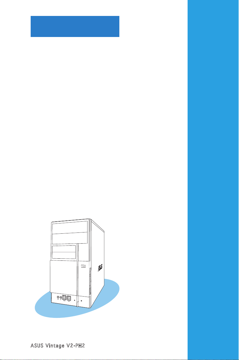
ASUS Vintage V2-PH2
Chapter 1
System introduction
This chapter gives a general
description of the ASUS
Vintage V2-PH2. The chapter lists
the system features including
introduction on the front and rear
panel, and internal components.
Page 12
1-2
Chapter 1: System introduction
1.1 Welcome!
Thank you for choosing the ASUS Vintage V2-PH2!
The ASUS Vintage V2-PH2 is an all-in-one barebone system with a versatile
home entertainment feature.
The system comes in a stylish mini-tower casing and powered by the ASUS
motherboard that supports the Intel® Pentium® D, Intel® Pentium® 4 or
Intel® Celeron® processor in the 775-land package.
The system supports up to 2 GB of system memory using
DDR2-667/533 DIMMs, ATI integrated graphics, Serial ATA, USB 2.0, and
6-channel audio features the system takes you ahead in the world of power
computing.
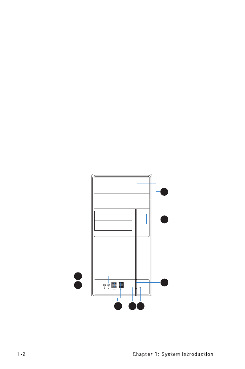
1.2 Front panel
The front panel includes the optical drive bays, floppy disk drive slot, power
button, and several I/O ports are located at the front panel.
1
2
3
456
7
8
Page 13
1-3
ASUS Vintage V2-PH2
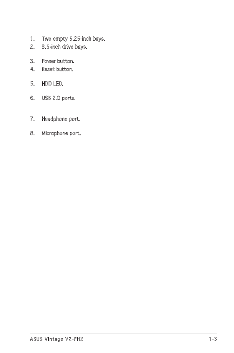
1. Two empty 5.25-inch bays. These bays are for IDE optical drives.
2. 3.5-inch drive bays. These slots are for 3.5-inch floppy or hard disk
drives.
3. Power button. Press this button to turn the system on.
4. Reset button. Press this button to reboot the system without turning
off the power.
5. HDD LED. This LED lights up when data is read from or written to the
hard disk drive.
6. USB 2.0 ports. These Universal Serial Bus 2.0 (USB 2.0) ports are
available for connecting USB 2.0 devices such as a mouse, printer,
scanner, camera, PDA, and others.
7. Headphone port. This Line In (green) port connects a headphone with
a stereo mini-plug.
8. Microphone port. This Mic (pink) port connects a microphone.
Page 14
1-4
Chapter 1: System introduction
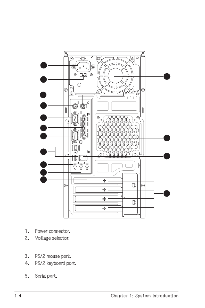
1.3 Rear panel
The system rear panel includes the power connector and several I/O ports
that allow convenient connection of devices.
1. Power connector. This connector is for the power cable and plug.
2. Voltage selector. This switch allows you to adjust the system input
voltage according to the voltage supply in your area. See the section
“Voltage selector” on page 1-6 before adjusting this switch.
3. PS/2 mouse port. This green 6-pin connector is for a PS/2 mouse.
4. PS/2 keyboard port. This purple 6-pin connector is for a
PS/2 keyboard.
5. Serial port. This port connects a mouse, modem, or other devices that
conform with serial specification.
10
11
12
1
2
4
5
6
7
8
9
3
14
15
13
Page 15
1-5
ASUS Vintage V2-PH2
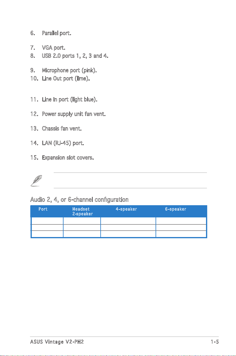
6. Parallel port. This 25-pin port connects a printer, scanner, or other
devices.
7. VGA port. This port connects a VGA monitor.
8. USB 2.0 ports 1, 2, 3 and 4. These 4-pin Universal Serial Bus (USB)
ports are available for connecting USB 2.0 devices.
9. Microphone port (pink). This port connects a microphone.
10. Line Out port (lime). This port connects a headphone or a speaker.
In 4-channel and 6-channel configuration, the function of this port
becomes Front Speaker Out.
11. Line In port (light blue). This port connects the tape, CD, DVD player,
or other audio sources.
12. Power supply unit fan vent. This vent is for the PSU fan that provides
ventilation inside the power supply unit.
13. Chassis fan vent. This vent is for the fan that provides ventilation
inside the system chassis.
14. LAN (RJ-45) port. This port allows Gigabit connection to a Local Area
Network (LAN) through a network hub.
15. Expansion slot covers. Remove these covers when installing expansion
cards.
Refer to the audio configuration table below for the function of the audio
ports in 2, 4, or 6-channel configuration.
Audio 2, 4, or 6-channel configuration
Light Blue Line In Surround Out Surround Out
Lime Line Out Front Speaker Out Front Speaker Out
Pink Mic In Mic Center/Bass
Por t He a d s et 4-s p e a ker 6-s p e a ker
2-spe a k e r
Page 16
1-6
Chapter 1: System introduction
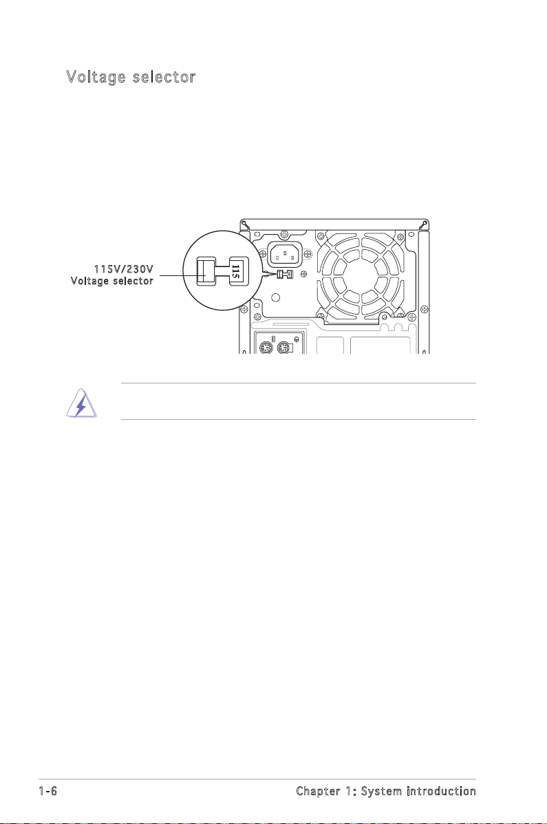
Vol ta ge se le ct or
The PSU has a 115 V/230 V voltage selector switch located beside the
power connector. Use this switch to select the appropriate system input
voltage according to the voltage supply in your area.
If the voltage supply in your area is 100-127 V, set this switch to 115 V.
If the voltage supply in your area is 200-240 V, set this switch to 230 V.
Setting the switch to 115V in a 230V environment or 230V in a 115V
environment will seriously damage the system!
115 V / 2 30V
Vol t a g e sel e c t or
Page 17
1-7
ASUS Vintage V2-PH2
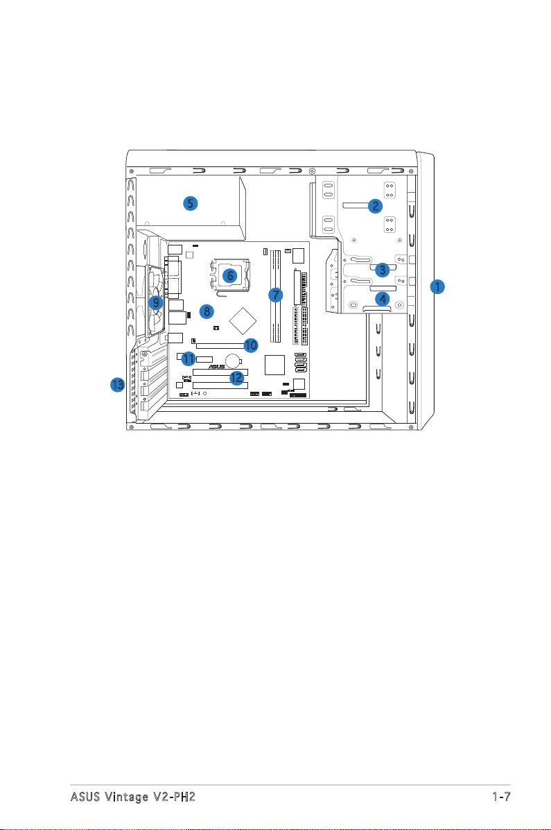
1.4 Internal components
The illustration below is the internal view of the system when you remove
the top cover and the power supply unit. The installed components are
labeled for your reference. Proceed to Chapter 2 for instructions on
installing additional system components.
1. Front panel cover
2. 5.25-inch optical drive bays
3. Hard disk drive bay
4. Floppy disk drive bay
5. Power supply unit
6. CPU socket
7. DIMM sockets
8. ASUS motherboard
9. Chassis fan
10. PCI Express x16 slot
11. PCI Express x1 slot
12. PCI slots
13. Metal bracket lock
CR20323V
LithiumCell
CMOSPowe
r
CD
Super
I/O
4M
BIOS
LPC
ATX12V
FLOPPY
AAFP
DDR2DIMM1 (64 bit,240-pin module)
SB_PWR
USB78
USB56
PCI1
ATI
RC410
ULI
M157
5
CHA_FAN2
CPU_FAN
PRI_IDE
EATXPWR
SPDIF_OUT
RTL8111B
PS/2KBMS
T:Mouse
B:Keyboard
Below:MicIn
Center:LineO
ut
Top:LineIn
USB12
LAN_USB34
PCIEX1_1
PCIEX16
COM1
PARALLELPORT
VGA1
®
SATA1
SEC_IDE
DDR2DIMM2 (64 bit,240-pin module)
PCI2
KBPWR
AUX
TV_C
USBPW34
USBPW12
AD1986A
LGA775
CHASSIS
SATA2
SATA3
SATA4
CLRTC
USBPW56
USBPW78
PANEL
CHA_FAN1
6
1
2
3
4
13
11
9
7
8
5
12
10
Page 18
1-8
Chapter 1: System introduction
Page 19
Chapter 2
Basic installation
This chapter provides step-by-step
instructions on how to install
components in the system.
Page 20
2-2
Chapter 2: Basic installation
2.1 Preparation
Before you proceed, make sure that you have all the components you plan
to install in the system.
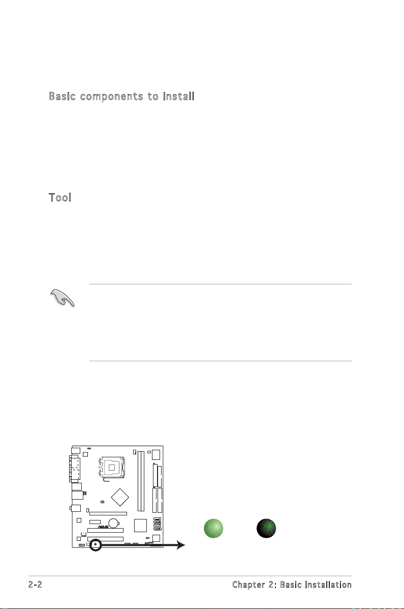
Bas i c c omp o ne n ts t o i nst a ll
1. Central Processing Unit (CPU)
2. DDR2 Dual Inline Memory Module (DIMM)
3. Expansion card(s)
4. Hard disk drive
5. Optical drive
6. Floppy disk drive
Too l
Phillips (cross) screw driver
The motherboard comes with an onboard standby power LED. This LED
lights up to indicate that the system is ON, in sleep mode or in soft-off
mode, and not powered OFF. Unplug the power cable from the power outlet
and make sure that the standby power LED is OFF before installing any
system component.
•
Use a grounded wrist strap or touch a safely grounded object or
a metal object, such as the power supply case, before handling
components to avoid damaging them due to static electricity.
•
Hold components by the edges to avoid touching the ICs on them.
•
Whenever you uninstall any component, place it on a grounded
antistatic pad or in the bag that came with the component.
2.2 Before you proceed
Take note of the following precautions before you install components into
the system.
®
Onboard LED
SB_PWR
ON
Standby
Power
OFF
Powered
Off
Page 21
2-3
ASUS Vintage V2-PH2
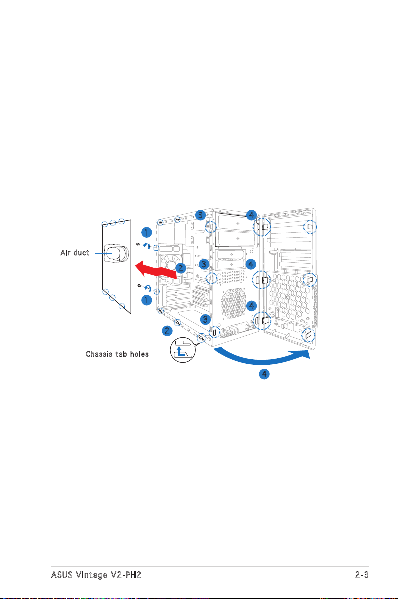
2.3 Removing the side cover and front
panel assembly
1. Remove the cover screws on the rear panel.
2. Pull the side cover toward the rear panel until its hooks disengage
from the chassis tab holes. Set the side cover aside.
3. Locate the front panel assembly hooks, then lift them until they
disengage from the chassis.
4. Swing the front panel assembly to the right, until the hinge-like tabs
on the right side of the assembly are exposed.
5. Remove the front panel assembly, then set aside.
1
1
2
2
4
3
4
4
3
3
Cha s s i s tab h o les
Air d u ct
4
Page 22
2-4
Chapter 2: Basic installation
2.4 Central Processing Unit (CPU)
2.4 .1 Ove rv ie w
The motherboard comes with a surface mount LGA775 socket designed for
the Intel® Pentium® 4 processor in the 775-land package.
• Your boxed Intel® Pentium® 4 LGA775 processor package should
come with installation instructions for the CPU, heatsink, and the
retention mechanism. If the instructions in this section do not match
the CPU documentation, follow the latter.
•
Check your motherboard to make sure that the PnP cap is on the
CPU socket and the socket contacts are not bent. Contact your
retailer immediately if the PnP cap is missing, or if you see any
damage to the PnP cap/socket contacts/motherboard components.
ASUS will shoulder the cost of repair only if the damage is shipment/
transit-related.
•
Keep the cap after installing the motherboard. ASUS will process
Return Merchandise Authorization (RMA) requests only if the
motherboard comes with the cap on the LGA775 socket.
• The product warranty does not cover damage to the socket
contacts resulting from incorrect CPU installation/removal, or
misplacement/loss/incorrect removal of the PnP cap.
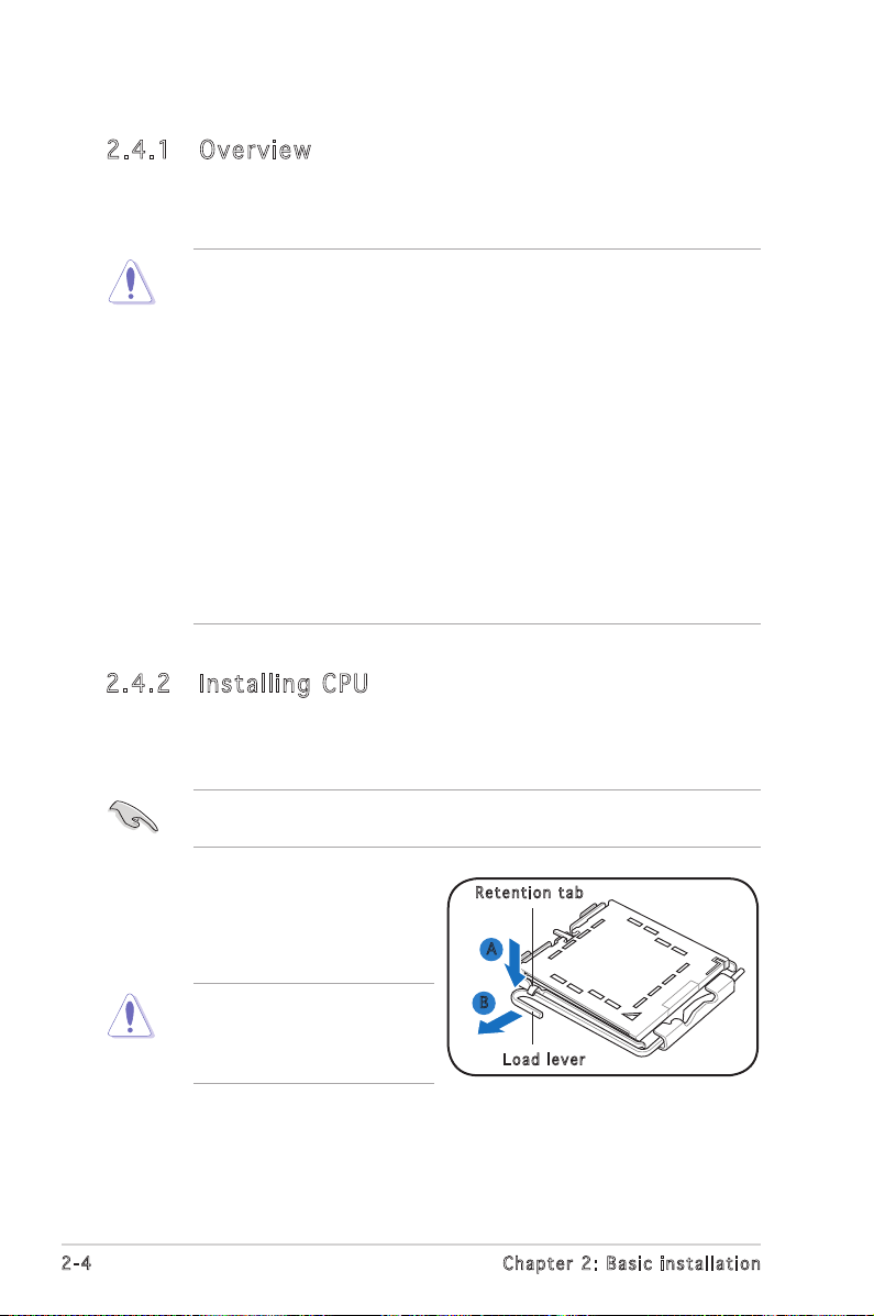
2.4 .2 Ins ta ll ing C PU
To install a CPU:
1. Locate the CPU socket on the motherboard.
Before installing the CPU, make sure that the socket box is facing
towards you and the load lever is on your left.
To prevent damage to the
socket pins, do not remove
the PnP cap unless you are
installing a CPU.
2. Press the load lever with your
thumb (A), then move it to the
left (B) until it is released from
the retention tab.
A
B
Loa d l ever
Ret e n t ion t a b
Page 23
2-5
ASUS Vintage V2-PH2
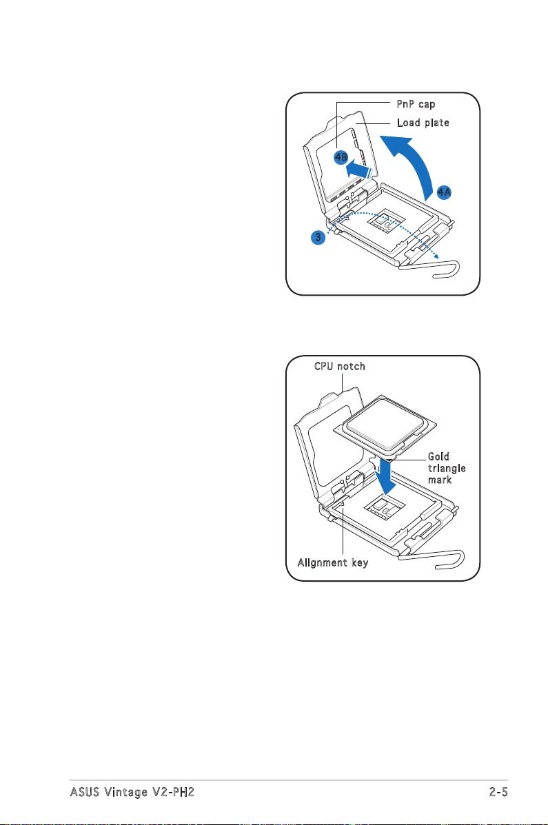
3. Lift the load lever in the
direction of the arrow to a 135º
angle.
4. Lift the load plate with your
thumb and forefinger to a 100º
angle (4A), then push the PnP
cap from the load plate window
to remove (4B).
5. Position the CPU over the
socket, making sure that
the gold triangle is on the
bottom-left corner of the socket
then fit the socket alignment
key into the CPU notch.
Gol d
tri a n g le
mar k
Ali g n m ent k e y
CPU n o tch
Loa d p late
PnP c a p
4A
4B
3
Page 24
2-6
Chapter 2: Basic installation
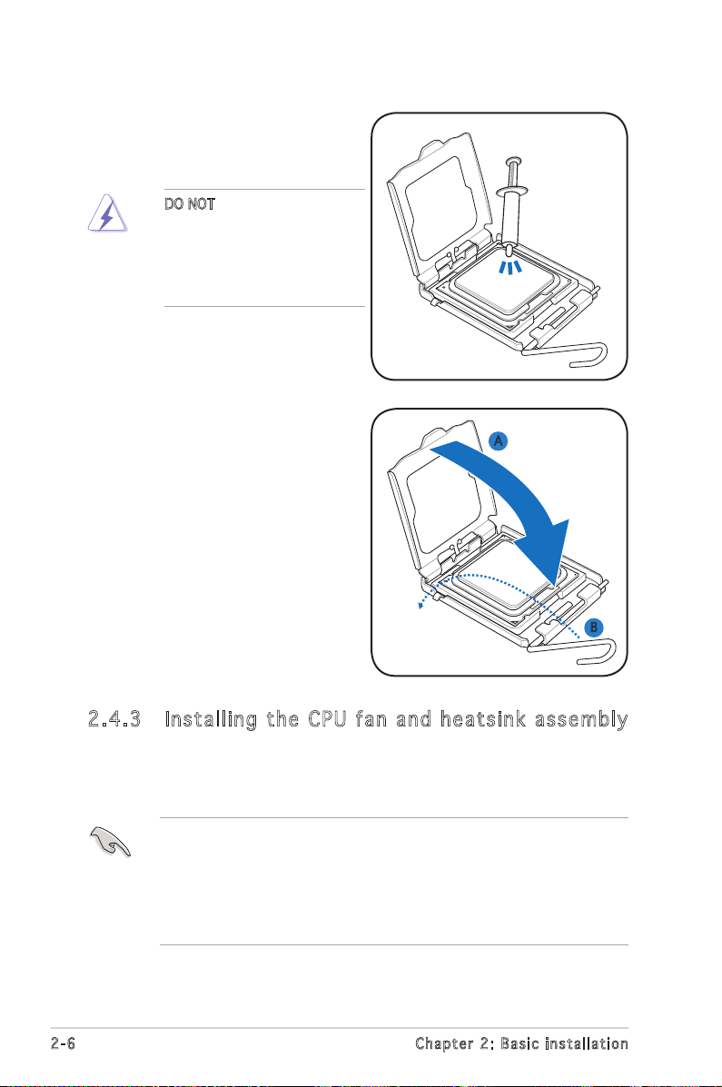
7. Close the load plate (A), then
push the load lever (B) until it
snaps into the retention tab.
6. Apply Thermal Interface Material
on the CPU before closing the
load plate.
A
B
DO NOT eat the Thermal
Interface Material. If it gets
into your eyes or touches
your skin, make sure to wash
it off immediately, and seek
professional medical help.
2.4 .3 Ins ta ll ing t he CP U f an a n d he ats in k a ss em bly
The Intel® Pentium® 4 LGA775 processor requires a specially designed
heatsink and fan assembly to ensure optimum thermal condition and
performance.
• When you buy a boxed Intel® Pentium® 4 processor, the package
includes the CPU fan and heatsink assembly. If you buy a
CPU separately, make sure that you use only Intel®-certified
multi-directional heatsink and fan.
• Your Intel® Pentium® 4 LGA775 heatsink and fan assembly comes in
a push-pin design and requires no tool to install.
Page 25
2-7
ASUS Vintage V2-PH2
If you purchased a separate CPU heatsink and fan assembly, make
sure that the Thermal Interface Material is properly applied to the CPU
heatsink or CPU before you install the heatsink and fan assembly.
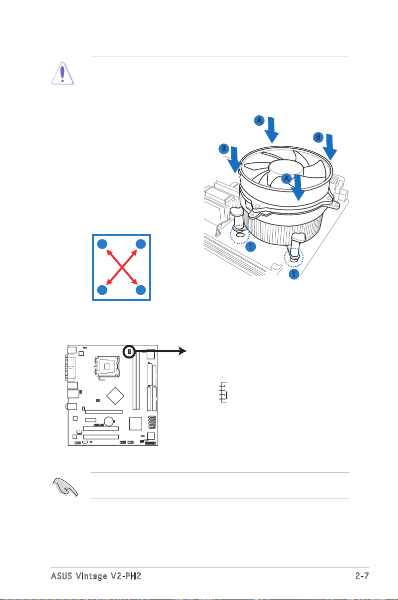
To install the CPU heatsink and fan:
1. Place the heatsink on top of the
installed CPU, making sure that
the four fasteners match the
holes on the motherboard.
3. When the fan and heatsink assembly is in place, connect the CPU fan
cable to the connector on the motherboard.
A
B
B
2. Push down two fasteners at
a time in a diagonal sequence
to secure the heatsink and fan
assembly in place.
Do not forget to connect the CPU fan connector! Hardware monitoring
errors can occur if you fail to plug this connector.
A
A
B
B
1
1
A
®
CPU Fan Connector
CPU_FA
N
GND
CPU F
AN PWR
CPU F
AN IN
CPU F
AN PWM
Page 26
2-8
Chapter 2: Basic installation
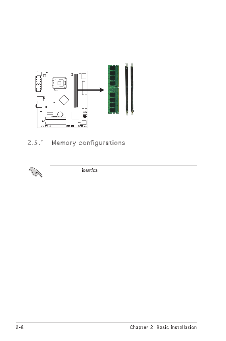
2.5 Installing a DIMM
The system motherboard comes with two Double Data Rate 2 (DDR2) Dual
Inline Memory Module (DIMM) sockets.
The following figure illustrates the location of the sockets:
• Install only identical (the same type and size) DDR2 memory
modules.
• Install only ASUS-certified memory modules. Refer to the DDR2
Qualified Vendors List on the next page for details. Visit the ASUS
website for the latest DDR2-533/667 MHz QVL
• Always install DIMMs with the same CAS latency. For optimum
compatibility, we recommend that you obtain memory modules from
the same vendor.
2.5 .1 Me m or y co n fi gu ra t io ns
You may install up to 2 GB system memory using 256 MB and 512 MB
DDR2 DIMMs.
240-pin DDR2 DIMM Sockets
DIMM2
DIMM1
®
Page 27
2-9
ASUS Vintage V2-PH2
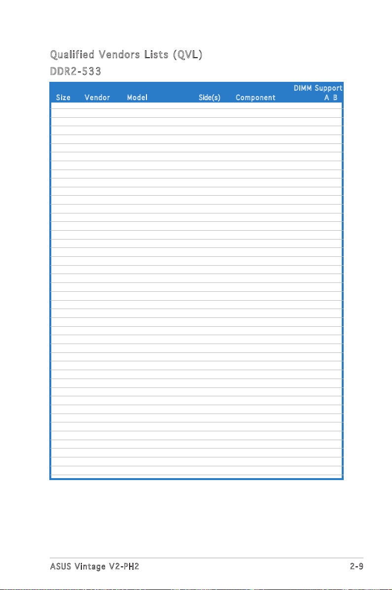
Siz e Ve n d o r Mod e l Side(s) C o m p o nent A B
DIM M S uppor t
512MB Infineon HYB18T512800AF37 SS HYS64T64000HU-3.7-A V V
1024MB Infineon HYB18T512800AF37 DS HYS64T128020HU-3.7-A V V
2048MB Infineon HYB18T1G800AF-3.7 DS HYS64T256020HU-3.7-A V
256MB Infineon HYB18T5121608BF-3.7 SS HYS64T32000HU-3.7-B V V
512MB Infineon HYB18T512800BF37 SS HYS64T64000HU-3.7-B V V
1024MB Infineon HYB18T512800BF37 DS HYS64T128020HU-3.7-B V V
512MB Hynix HY5PS12821F-C4 SS HYMP564U648-C4 V
1024MB Hynix HY5PS12821FP-C4 DS HYMP512U648-C4 V V
512MB Hynix HY5PS12821AFP-C3 SS HYMP564U64AP8-C3 V
1024MB Hynix HY5PS12821AFP-C3 DS HYMP512U64AP8-C3 V V
512MB ELPIDA E5108AB-5C-E SS EBE51UD8ABFA-5C V V
512MB ELPIDA E5108AB-5C-E SS EBE51UD8ABFA-5C-E V V
1024MB ELPIDA E5108AB-5C-E DS EBE11UD8ABFA-5C-E V V
2048MB ELPIDA E1108AA-5C-E DS EBE21EE8AAFA-5C-E V
256MB CORSAIR MIII0051832M8CEC SS VS256MB533D2 V V
512MB CORSAIR MI110052432M8CEC DS VS512MB533D2 V
256MB Apacer E5116AB-5C-E SS 78.81077.420 V V
256MB KINGMAX E5116AB-5C-E SS KLBB68F-36EP4 V V
512MB KINGMAX E5108AE-5C-E SS KLBC28F-A8EB4 V V
1024MB KINGMAX E5108AE-5C-E DS KLBD48F-A8EB4 V V
512MB Transcend K4T51083QB-GCD5 SS TS64MLQ64V5J V
1024MB Transcend K4T51083QB-GCD5 DS TS128MLQ64V5J V V
256MB CENTURY K4T56083QF-GCD5 SS 25V6S8SSD5F4-K43 V V
1024MB CENTURY E5108AB-5C-E DS 25V0H8EL5CB4-J45 V V
512MB elixir N2TU51280AF-37B SS M2U51264TU88A0F-37B V
256MB Aeneon AET960UD00-37C88X SS AET560UD00-370A98X V
256MB Aeneon AET94F370A SS AET560UD00-370A98X V V
512MB Aeneon AET93F370A SS AET660UD00-370A98Z V V
1024MB Aeneon AET93F370A DS AET760UD00-370A98X V V
512MB NANYA NT5TU64M8AF-37B SS NT512T64U88A0F-37B V V
512MB PQI 64MX8D2-E SS MEAB-423LA V
1024MB Patriot Heat-Sink Package SS PDC21G5600+XBLK V
512MB MDT 18D51280D-3.70S20 SS M512-533-8 V
Qua l if i ed V en d ors Li s ts ( QV L )
DDR 2 -53 3
256MB KINGSTON E5116AB-5C-E SS KVR533D2N4/256 V V
512MB KINGSTON HY5PS56821F-C4 DS KVR533D2N4/512 V V
1024MB KINGSTON D6408TE7BL-37 DS KVR533D2N4/1G V V
2048MB KINGSTON E1108AA-5C-E DS KVR533D2N4/2G V
512MB SAMSUNG K4T51083QB-GCD5 SS M378T6553BG0-CD5 V V
256MB SAMSUNG K4T56083QF-GCD5 SS M378T3253FG0-CD5 V V
512MB SAMSUNG K4T56083QF-GCD5 DS M378T6453FG0-CD5 V V
256MB MICRON 4DBIIZ9BQT SS N/A V V
512MB Infineon HYB18T512800AC37 SS HYS64T64000GU-3.7-A V V
256MB Infineon HYB18T512160AF-3.7 SS HYS64T32000HU-3.7-A V V
Page 28
2-10
Chapter 2: Basic installation
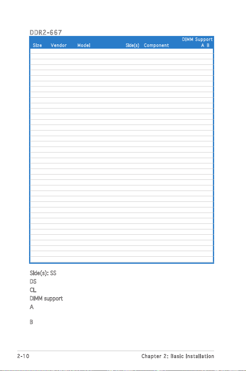
Siz e Ve n d o r Mod e l Side(s) Compo n e n t A B
DDR 2 -66 7
DIM M S uppor t
Side(s): SS - Single-sided
DS - Double-sided
CL: CAS Latency
DIMM support:
A -Supports one module inserted into either slot, in Single-channel memory
configuration.
B -Supports one pair of modules inserted into both slots as one pair of
Dual-channel memory configuration.
512MB KINGSTON E5108AE-6E-E SS KVR667D2N5/512 V V
1024MB KINGSTON E5108AE-6E-E DS KVR667D2N5/1G V V
512MB KINGSTON E5108AE-6E-E SS KVR667D2E5/512 V V
256MB KINGSTON HYB18T256800AF3 SS KVR667D2N5/256 V V
256MB SAMSUNG K4T56083QF-ZCE6 SS M378T3253FZ0-CE6 V V
512MB SAMSUNG K4T56083QF-ZCE6 DS M378T6453FZ0-CE6 V V
256MB SAMSUNG K4T51163QC-ZCE6 SS M378T3354CZ0-CE6 V V
512MB SAMSUNG ZCE6K4T51083QC SS M378T6553CZ0-CE6 V V
1024MB SAMSUNG ZCE6K4T51083QC DS M378T2953CZ0-CE6 V
256MB MICRON 4SB42D9CZM SS MT8HTF3264AY-667B5 V V
512MB MICRON 4VB41D9CZM DS MT16HTF6464AY-667B4 V V
256MB Infineon HYB18T512160AF-3S SS HYS64T32000HU-3S-A V V
512MB Infineon HYB18T512800AF3S SS HYS64T64000HU-3S-A V V
1024MB Infineon HYB18T512800AF3S DS HYS64T128020HU-3S-A V
512MB Hynix HY5PS12821AFP-Y5 SS HYMP564U64AP8-Y5 V V
1024MB Hynix HY5PS12821AFP-Y5 DS HYMP512U64AP8-Y5 V V
512MB Hynix HY5PS12821AFP-Y4 SS HYMP564U64AP8-Y4 V V
1024MB Hynix HY5PS12821AFP-Y4 DS HYMP512U64AP8-Y4 V V
256MB ELPIDA E2508AB-GE-E SS EBE25UC8ABFA-6E-E V V
512MB ELPIDA E5108AE-GE-E SS EBE51UD8AEFA-6E-E V V
1024MB ELPIDA Engineering Sample DS EBE11UD8AEFA-6E-E V V
1024MB crucial Heat-Sink Package DS BL12864AA664.16FA V V
512MB crucial Heat-Sink Package DS BL6464AL664.16FB V V
1024MB crucial Heat-Sink Package DS BL12864AL664.16FA V V
512MB Kingmax E5108AE-6E-E SS KLCC28F-A8EB5 V V
1024MB Kingmax E5108AE-6E-E DS KLCD48F-A8EB5 V
512MB Apacer E5108AE-6E-E SS 78.91092.420 V
1024MB Apacer E5108AE-6E-E DS 78.01092.420 V
512MB A-DATA E5108AE-6E-E SS M20EL5G3H3160B1C0Z V V
512MB TwinMOS E5108AE-GE-E SS 8G-25JK5-EBT V V
512MB GEIL Heat-Sink Package SS GX21GB5300UDC V V
512MB GEIL Heat-Sink Package SS GX21GB5300DC V V
256MB NANYA NT5TU32M16AG-3C SS NT256T64UH4A0FY-3C V
512MB NANYA NT5TU64M8AE-3C SS NT512T64U88A0BY-3C V
512MB OCZ Heat-Sink Package SS OCZ26671024EBDCPE-K V V
512MB WINTEC 4UAI2D9CRZ SS 39127282 V V
1024MB WINTEC 4WAIID9CWX DS 39137282 V
512MB MDT 18D51280D-30518 SS M512-667-8 V V
1024MB MDT 18D51280D-30528 DS M924-667-16 V
Page 29
2-11
ASUS Vintage V2-PH2
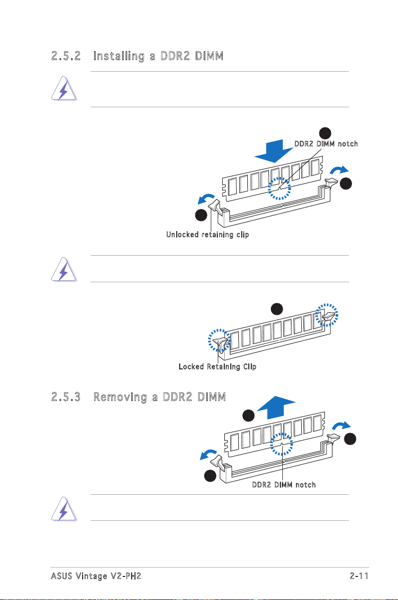
2.5 .3 Rem ov in g a D DR 2 D IM M
Follow these steps to remove a DIMM.
1. Simultaneously press the
retaining clips outward to
unlock the DIMM.
2. Remove the DIMM from the socket.
Support the DIMM lightly with your fingers when pressing the retaining
clips. The DIMM might get damaged when it flips out with extra force.
2.5 .2 Ins ta ll ing a D DR2 D IM M
3. Firmly insert the DIMM into the
socket until the retaining clips
snap back in place and the DIMM
is properly seated.
1. Unlock a DDR2 DIMM socket
by pressing the retaining clips
outward.
2. Align a DIMM on the socket
such that the notch on the
DIMM matches the break on
the socket.
Loc k e d Reta i n i ng Cl i p
Make sure to unplug the power supply before adding or removing DIMMs
or other system components. Failure to do so may cause severe damage
to both the motherboard and the components.
A DDR2 DIMM is keyed with a notch so that it fits in only one direction.
DO NOT force a DIMM into a socket to avoid damaging the DIMM.
DDR 2 D IMM n o t c h
1
2
1
3
Unl o c k ed re t a i ning c l i p
1
1
DDR 2 D IMM n o t c h
2
Page 30
2-12
Chapter 2: Basic installation
2.6 Expansion slots
In the future, you may need to install expansion cards. The following
sub-sections describe the slots and the expansion cards that they support.
2.6 .1 Ins ta ll ing a n ex p an si on ca rd
To install an expansion card:
1. Before installing the expansion card, read the documentation that
came with it and make the necessary hardware settings for the card.
2. Remove the system unit cover (if your motherboard is already
installed in a chassis).
3. Remove the bracket opposite the slot that you intend to use. Keep
the screw for later use.
4. Align the card connector with the slot and press firmly until the card is
completely seated on the slot.
5. Secure the card to the chassis with the screw you removed earlier.
6. Replace the system cover.
Make sure to unplug the power cord before adding or removing
expansion cards. Failure to do so may cause you physical injury and
damage motherboard components.
2.6 .2 Con fi gu rin g an e x pa ns io n c ar d
After installing the expansion card, configure it by adjusting the software
settings.
1. Turn on the system and change the necessary BIOS settings, if any.
See Chapter 5 for information on BIOS setup.
2. Assign an IRQ to the card. Refer to the tables on the next page.
3. Install the software drivers for the expansion card.
Page 31

2-13
ASUS Vintage V2-PH2
* T h e s e IRQ s a re us u a l l y av a i l a ble f o r ISA o r P CI d e v i c es.
When using PCI cards on shared slots, ensure that the drivers support
“Share IRQ” or that the cards do not need IRQ assignments. Otherwise,
conflicts will arise between the two PCI groups, making the system
unstable and the card inoperable.
Sta n da r d i n te r rup t a s sig n me n ts
IRQ St a ndar d F u ncti o n
0 System Timer
1 Keyboard Controller
2 Re-direct to IRQ#9
4 Communications Port (COM1)*
5 IRQ holder for PCI steering*
6 Floppy Disk Controller
7 Printer Port (LPT1)*
8 System CMOS/Real Time Clock
9 IRQ holder for PCI steering*
10 IRQ holder for PCI steering*
11 IRQ holder for PCI steering*
12 PS/2 Compatible Mouse Port*
13 Numeric Data Processor
14 Primary IDE Channel
15 Secondary IDE Channel
IRQ as s ign m en t s f o r t his mo t her b oa r d
A B C D E F G H
PCI slot 1 shared — — — — — — —
PCI slot 2 — shared — — — — — —
PCI Express x16 slot shared — — — — — — —
PCI Express x1 slot — shared — — — — — —
Onboard USB controller 1 — — — — — — — shared
Onboard USB controller 2 — — — shared — — — —
Onboard USB controller 3 — — shared — — — — —
Onboard USB controller 4 — — — shared — — — —
Onboard USB 2.0 controller — — — — — — — shared
Onboard IDE port — — — shared — — — —
Onboard HD audio shared — — — — — — —
Onboard LAN — shared — — — — — —
Page 32

2-14
Chapter 2: Basic installation
2.6 .4 PCI s lo ts
The PCI slots support cards such as
a LAN card, SCSI card, USB card, and
other cards that comply with PCI
specifications. The figure shows a
LAN card installed on a PCI slot.
2.6 .3 PCI E xp res s x1 sl ot
This motherboard supports PCI
Express x1 network cards, SCSI cards
and other cards that comply with the
PCI Express specifications. The figure
shows a network card installed on the
PCI Express x1 slot.
Before using a PCI VGA card,
make sure to set the Boot
Graphics Adapter Priority
to PCI/IGD in the BIOS. See
section “5.4.4 Chipset->
NorthBridge Configuration” for
details.
2.6 .5 PCI E xp res s x1 6 s lo t
This motherboard supports PCI
Express x16 graphic cards that
comply with the PCI Express
specifications. The figure shows a
graphics card installed on the PCI
Express x16 slot.
Page 33

2-15
ASUS Vintage V2-PH2
2.7 Installing an optical drive
Refer to the instructions in this section if you wish to install a new optical
drive.
Follow these steps to install an optical drive:
1. Place the chassis upright.
2. Remove the drive slot metal plate cover.
3. Insert the optical drive into the upper 5.25-inch drive bay and
carefully push the optical drive into the bay until its screw holes align
with the holes on the bay as shown.
4. Secure the optical drive with two screws on both sides of the bay.
4
4
3
IDE r i bbon c a b le
Pow e r cable
5. Connect a power cable from
the power supply to the power
connector at the back of the
optical drive.
6. Connect one end of the IDE
ribbon cable to the IDE interface
at the back of the optical drive,
matching the red stripe on the
cable with Pin 1 on the IDE
interface.
Page 34

2-16
Chapter 2: Basic installation
7. Connect the other end of the IDE ribbon cable to the secondary IDE
connector (labeled SEC_IDE) on the motherboard. See page 4-7 for
the location of this connector.
8. Remove the dummy drive slot cover from the front panel.
9. Replace the front panel. Refer to section “2.11 Removing the bay
covers and reinstalling the front panel assembly and side cover” on
page 2-22 for details.
Page 35

2-17
ASUS Vintage V2-PH2
2.8 Installing a hard disk drive
The system may have one pre-installed 3.5-inch Serial ATA or IDE hard disk
drive. Refer to this section to install additional Serial ATA or IDE hard disk
drive(s).
To install a Serial ATA hard disk drive:
4. Secure the drive with two screws on both sides.
4
4
3
1. Place the chassis upright.
2. Use a screw driver to remove the HDD drive slot metal plate cover.
3. With the HDD label side up, carefully insert the drive into the 3.5-inch
bay and push the drive into the bay until its screw holes align with the
holes on the drive bay.
Page 36

2-18
Chapter 2: Basic installation
If your Serial ATA HDD has both 4-pin and 15-pin connectors at the
back, use either the 15-pin SATA power adapter plug OR the legacy
4-pin power connector. DO NOT use both to prevent damage to
components and to keep the system from becoming unstable.
5. Connect one end of the Serial ATA cable to the SATA connector at
the back of the drive, then connect the other end to a Serial ATA
connector on the motherboard. See page 4-6 for the location of the
Serial ATA connectors.
6. Connect a 15-pin Serial ATA power plug from the power supply unit to
the 15-pin power connector at the back of the drive.
- OR -
Connect a 4-pin (female) power plug from the power supply unit to
the 4-pin (male) power connector at the back of the drive.
Ser i a l ATA c a b le
Ser i a l ATA p o w er
cab l e
Page 37

2-19
ASUS Vintage V2-PH2
To install an IDE hard disk drive:
1. Follow steps 1-4 of the previous section.
2. Connect the blue interface of the IDE ribbon cable to the primary IDE
connector (blue connector labeled PRI_IDE) on the motherboard. See
page 4-7 for the location of the connector.
• If you will install only one hard disk drive, make sure to configure
your hard disk drive as Master device before connecting the IDE
cable and power plug. Refer to the HDD documentation on how to
set the drive as a Master device.
• If you will install two IDE hard disk drives, configure the other device
as Slave.
3. Connect the gray interface of the IDE ribbon cable to the IDE
connector on the drive.
4. If you install two IDE hard disk drives, connect the black interface of
the IDE ribbon cable to the IDE connector on the second (Slave) IDE
hard disk drive.
5. Connect a 4-pin power plug from the power supply unit to the power
connector at the back of the drive(s).
IDE r i bbon c a b le
Pow e r cable
Page 38

2-20
Chapter 2: Basic installation
2.9 Installing a floppy disk drive
The Vintage V2-PH2 system comes with one 3.25-inch drive bay for a
floppy disk drive.
To install a floppy disk drive:
1. Remove the front panel cover.
For instructions on how to remove the front panel cover, refer to page
2-3 of section “2.3 Removing the side cover and front panel assembly”.
2. Carefully insert the floppy disk drive into the floppy drive bay until the
screw holes align with the holes on the bay.
3. Secure the floppy disk drive with two screws on both sides.
4. Connect the floppy disk drive signal cable to the signal connector at
the back of the drive.
3
3
2
5. Connect the other end of the signal cable to the floppy disk drive
connector on the motherboard. See page 4-6 for the location of the
floppy disk drive connector.
6. Connect a 4-pin power cable from the power supply unit to the power
connector at the back of the floppy disk drive.
Flo p p y ribb o n
cab l e
Pow e r cable
Page 39

2-21
ASUS Vintage V2-PH2
2.10 Re-connecting cables
You may have disconnected some cables when you were installing
components. You must re-connect these cables before you replace the
chassis cover.
LED c ab les
Connect the reset button, power switch, power LED, and HDD LED
cables to their respective leads in the system panel connector on the
motherboard. See page 4-12 for the system panel descriptions.
HDD L E D
Pow e r LED
Pow e r Switc h
Res e t butto n
System Panel Connector
* Requires an ATX power supply.
®
PANEL
PLED-
PWR
+5V
Speaker
Ground
RESET
Ground
Reset
Ground
Ground
PWRSW
PLED+
IDE_LED-
IDE_LED+
IDE_LED
PLED SPEAKER
I
Page 40

2-22
Chapter 2: Basic installation
2.11 Removing the bay covers and
reinstalling the front panel assembly
and side cover
If you installed an optical and/or floppy disk drive, remove the bay cover(s)
on the front panel assembly before
reinstalling it to the chassis. To do
this:
1. Locate the bay cover locks.
2. Press the locks outward to
release the bay cover.
3. Push the bay cover inward, then
set it aside.
4. Follow the same instructions to remove the 3.5” drive bay cover.
To reinstall the front panel assembly and side cover:
1. Insert the front panel assembly hinge-like tabs to the holes on the
right side of the chassis.
2. Swing the front panel assembly to the left, then insert the hooks to
the chassis until the front panel assembly fits in place.
3. Insert the six side cover hooks into the chassis tab holes .
4. Push the side cover to the direction of the front panel until it fits in place.
5. Secure the cover with two screws you removed earlier.
If the air duct interferes with the CPU fan, adjust the air duct accordingly.
Air d u ct
2
1
3
2
5
5
1
1
2
2
4
Cha s s i s tab h o les
Page 41

ASUS Vintage V2-PH2
Chapter 3
Starting up
This chapter helps you power up
the system and install drivers and
utilities from the support CD.
Page 42

3-2
Chapter 3: Starting up
3.1 Installing an operating system
The barebone system supports Windows® 2000/XP operating systems
(OS). Always install the latest OS version and corresponding updates so
you can maximize the features of your hardware.
3.3 Support CD information
The support CD that came with the system contains useful software and
several utility drivers that enhance the system features.
3.2 Powering up
Press the system power button ( ) to enter the OS.
Pre s s to tu r n ON th e s y stem
Because motherboard settings and hardware options vary, use the setup
procedures presented in this chapter for general reference only. Refer to
your OS documentation for more information.
•
Screen display and driver options may not be the same for different
operating system versions.
•
The contents of the support CD are subject to change at any time
without notice. Visit the ASUS website for updates.
• Windows XP OS setup cannot recognize Serial ATA hard drives
without the necessary drivers. Use the bundled floppy disk when
installing Windows XP OS to a Serial ATA hard drive.
• From the Windows XP setup screen, press F6 when prompted then
follow succeeding screen instructions to install the SATA drivers.
Page 43

3-3
ASUS Vintage V2-PH2
3.3 .1 Run ni ng th e su ppo rt C D
To begin using the support CD, place the CD in your optical drive. The
CD automatically displays the Drivers menu if Autorun is enabled in your
computer.
If Autorun is NOT enabled in your computer, browse the contents of the
support CD to locate the file ASSETUP.EXE from the BIN folder.
Double-click the ASSETUP.EXE to run the CD.
Cli c k an it e m to in s t a ll
Cli c k an ic o n to
dis p l a y sup p o r t
CD/ m o t herbo a r d
inf o r m ation
ASU S I n stA l l - Dr i ve r s I n st a lla t io n Wi z ar d
Automatically installs all the necessary drivers for this motherboard.
ATI Ra d eon Xp r ess 200 Di s pla y D r ive r
Installs the ATI Radeon Xpress 200 display driver.
ULi M15 75 C hip s et Dri v er
Installs the ULi M1575 chipset driver.
Rea l te k RT L 81 1 1b 1 0/1 0 0/ 1 000 M L A N D r iv e r
Installs the Realtek RTL8111b 10/100/1000M LAN Driver.
ADI AD 1 986 A Au d io Dri v er
Allows you to install the ADI AD1986A audio driver.
USB 2.0 Dr i ver
Installs the USB 2.0 driver file that came with the utility for details.
Page 44

3-4
Chapter 3: Starting up
3.3 .2 Uti li ti es me nu
The Utilities menu shows the applications and other software that the
motherboard supports.
ASU S I n stA l l- I nst a ll a tio n W i zar d f o r U t ili tie s
Installs the ASUS InstAll-Installation Wizard Utilities.
ASU S P C Pr o be II
This smart utility monitors the fan speed, CPU temperature, and system
voltages, and alerts you of any detected problems. This utility helps you keep
your computer in healthy operating condition.
ASU S U p dat e
The ASUS Update utility allows you to update the motherboard BIOS in a
Windows® environment. This utility requires an Internet connection either through
a network or an Internet Service Provider (ISP). See page 5-8 for details.
ADO B E A cro b at Rea d er V7. 0
Installs the Adobe® Acrobat® Reader V7.0 that allows you to open, view, and
print documents in Portable Document Format (PDF).
Mic r os o ft D ir e ctX 9. 0 c
Installs the Microsoft® DirectX 9.0c driver.
Ant i -v i rus ut i lit y
The anti-virus application scans, identifies, and removes computer viruses. View
the online help for detailed information.
ASU S S c ree n S a ver
Installs the ASUS screen saver.
Page 45

3-5
ASUS Vintage V2-PH2
3.3 .4 Man ua ls me nu
The Manuals menu contains a list of supplementary user manuals. Click an
item to open the folder of the user manual.
Most user manual files are in Portable Document Format (PDF). Install
the Adobe® Acrobat® Reader from the Utilities menu before opening a
user manual file.
3.3 .3 Mak e Di sk
Mak e U L i S A TA RAI D 5 D riv e r D isk
Creates the ULi SATA RAID5 driver disk.
ULI SA T A/R A ID Use r ʼs Man u al
Allows you to open the ULI SATA/RAID Userʼs Manual.
Page 46

3-6
Chapter 3: Starting up
3.4 Software information
Most of the applications in the support CD have wizards that will
conveniently guide you through the installation. View the online help or
readme file that came with the software for more information.
3.3 .5 ASU S Co nta ct i nfo rm at ion
Click the Contact tab to display the ASUS contact information. You can also
find this information on the inside front cover of this user guide.
ASU S PC Pr ob e II
PC Probe II is a utility that monitors the computerʼs vital components
and alerts you of any problem with these components. PC Probe II senses
fan rotations, CPU temperature, and system voltages, among others. PC
Probe II is software-based, allowing you to start monitoring your computer
the moment you turn it on. With this utility, you are assured that your
computer is always at a healthy operating condition.
Page 47

3-7
ASUS Vintage V2-PH2
Ins t al l ing PC Pro b e I I
To install PC Probe II on your computer:
1. Place the support CD to the optical drive. The Drivers installation tab
appears if your computer has an enabled Autorun feature.
Cli c k to cl o s e the
Pre f e r ence p a n el
2. Click the Utilities tab, then click ASUS PC Probe II.
3. Follow the screen instructions to complete installation.
Lau n ch i ng P C P rob e I I
You can launch the PC Probe II right after installation or anytime from the
Windows® desktop.
To launch the PC Probe II from the Windows® desktop, click Start > All
Programs > ASUS > PC Probe II. The PC Probe II main window appears.
After launching the application, the PC Probe II icon appears in the
Windows® taskbar. Click this icon to close or restore the application.
Usi n g P C P r ob e II
Main window
The PC Probe II main window allows
you to view the current status of
your system and change the utility
configuration. By default, the main
window displays the Preference
section. You can close or restore
the Preference section by clicking
on the triangle on the main window
right handle.
If Autorun is not enabled in your computer, browse the contents of the
support CD to locate the setup.exe file from the ASUS PC Probe II folder.
Double-click the setup.exe file to start installation.
Page 48

3-8
Chapter 3: Starting up
But t o n Func t i o n
Opens the Configuration window
Opens the Report window
Opens the Desktop Management Interface window
Opens the Peripheral Component Interconnect window
Opens the Windows Management Instrumentation window
Opens the hard disk drive, memory, CPU usage window
Shows/Hides the Preference section
Minimizes the application
Closes the application
Sensor alert
When a system sensor detects a problem, the main window right handle
turns red, as the illustrations below show.
When displayed, the monitor panel for that sensor also turns red. Refer to
the Monitor panels section for details.
Pre f er e nce s
You can customize the application using the
Preference section in the main window. Click
the box before each preference to activate or
deactivate.
Page 49

3-9
ASUS Vintage V2-PH2
Har d wa r e m o ni t or p an e ls
The hardware monitor panels display the current value of a system sensor
such as fan rotation, CPU temperature, and voltages.
The hardware monitor panels come in two display modes: hexagonal (large)
and rectangular (small). When you check the Enable Monitoring Panel
option from the Preference section, the monitor panels appear on your
computerʼs desktop.
Changing the monitor panels position
To change the position of the monitor panels on the desktop,
click the arrow down button of the Scheme options, then
select another position from the list box. Click OK when
finished.
Moving the monitor panels
All monitor panels move together using
a magnetic effect. If you want to detach
a monitor panel from the group, click the
horseshoe magnet icon. You can now move
or reposition the panel independently.
Adjusting the sensor threshold value
You can adjust the sensor threshold
value in the monitor panel by clicking
the arrow buttons. You can also
adjust the threshold values using the
Config window.
You cannot adjust the sensor threshold
values in a small monitoring panel.
Lar g e displ a y
Sma l l displ a y
Cli c k to
inc r e a se
val u e
Cli c k to
dec r e a se
val u e
Page 50

3-10
Chapter 3: Starting up
Monitoring sensor alert
The monitor panel turns red when a component value exceeds or is lower
than the threshold value. Refer to the illustrations below.
Lar g e displ a y
Sma l l displ a y
WMI br o wse r
Click to display the
WMI (Windows Management
Instrumentation) browser. This
browser displays various Windows®
management information. Click an
item from the left panel to display
on the right panel. Click the plus
sign (+) before WMI Information to
display the available information.
You can enlarge or reduce the browser size by dragging the bottom right
corner of the browser.
DMI br o wse r
Click to display the DMI
(Desktop Management Interface)
browser. This browser displays
various desktop and system
information. Click the plus sign (+)
before DMI Information to display
the available information.
Page 51

3-11
ASUS Vintage V2-PH2
PCI br o wse r
Click to display the
PCI (Peripheral Component
Interconnect) browser. This
browser provides information on
the PCI devices installed on your
system. Click the plus sign (+)
before the PCI Information item to
display available information.
Usa g e
The Usage browser displays real-time information on the CPU, hard disk
drive space, and memory usage. Click to display the Usage browser.
CPU usage
The CPU tab displays real-time CPU
usage in line graph representation.
If the CPU has an enabled HyperThreading, two separate line graphs
display the operation of the two
logical processors.
Hard disk drive space usage
The Hard Disk tab displays the used
and available hard disk drive space.
The left panel of the tab lists all
logical drives. Click a hard disk drive
to display the information on the
right panel. The pie chart at the
bottom of the window represents
the used (blue) and the available
HDD space.
Page 52

3-12
Chapter 3: Starting up
Memory usage
The Memory tab shows both used
and available physical memory.
The pie chart at the bottom of the
window represents the used (blue)
and the available physical memory.
Con f ig u rin g P C Pr o be II
Click to view and adjust the sensor threshold values.
The Config window has two tabs: Sensor/Threshold and Preference. The
Sensor/Threshold tab enables you to activate the sensors or to adjust the
sensor threshold values. The Preference tab allows you to customize sensor
alerts, change temperature scale, or enable the Q-Fan feature.*
*Av a i l able o n some m o t herbo a r d s onl y .
Loa d s the d e f a u lt
thr e s h old v a l u es
for e a ch se n s o r
App l i e s you r
cha n g e s
Can c e l s or
ign o r e s you r
cha n g e s
Lo ads y our s ave d
co nfigu ratio n
Sav e s your
con f i g urati o n
Page 53

ASUS Vintage V2-PH2
Chapter 4
Motherboard info
This chapter gives information
about the motherboard that comes
with the system. This chapter
includes the motherboard layout,
jumper settings, and connector
locations.
Page 54

4-2
Chapter 4: Motherboard info
4.1 Introduction
The Vintage V2-PH2 barebone system comes with an ASUS motherboard.
This chapter provides technical information about the motherboard for
future upgrades or system reconfiguration.
4.2 Motherboard layout
CR2032 3V
Lithium Cell
CMOS Powe
r
CD
Super
I/O
4M
BIOS
LPC
ATX12V
FLOPPY
AAFP
DDR2 DIMM1 (64 bit,240-pin module)
SB_PWR
USB56
USB78
PCI1
ATI
RC410
ULI
M157
5
CHA_FAN2
CPU_FAN
PRI_IDE
EATXPWR
SPDIF_OUT
RTL8111B
PS/2KBMS
T: Mouse
B: Keyboard
Below:Mic In
Center:Line O
ut
Top:LineIn
USB12
LAN_USB34
PCIEX1_1
PCIEX16
COM1
PARALLEL PORT
VGA1
®
SATA1
SEC_IDE
DDR2 DIMM2 (64 bit,240-pin module)
PCI2
KBPWR
AUX
TV_C
USBPW34
USBPW12
AD1986A
24.3cm (9.6in)
21.8cm (8.6in)
LGA775
CHASSIS
SATA2
SATA3
SATA4
CLRTC
USBPW56
USBPW78
PANEL
CHA_FAN1
Page 55

4-3
ASUS Vintage V2-PH2
4.3 Jumpers
1. Clea r R TC R A M (CLR T C )
This jumper allows you to clear the Real Time Clock (RTC) RAM in
CMOS. You can clear the CMOS memory of date, time, and system
setup parameters by erasing the CMOS RTC RAM data. The onboard
button cell battery powers the RAM data in the CMOS, which includes
the system setup information such as system passwords.
To erase the RTC RAM:
1. Turn OFF the computer and unplug the power cord.
2. Remove the battery.
3. Move the jumper cap from pins 1-2 (default) to pins 2-3. Keep
the cap on pins 2-3 for about 5-10 seconds, then move the cap
back to pins 1-2.
4. Re-install the battery.
5. Plug the power cord and turn ON the computer.
6. Hold down the <Del> key during the boot process and enter BIOS
setup to re-enter data.
Except when clearing the RTC RAM, never remove the cap on CLRTC
jumper default position. Removing the cap will cause system boot failure.
Clear RTC RAM
CLRTC
Normal Clear CMOS
(Default)
1
2
2
3
®
Page 56

4-4
Chapter 4: Motherboard info
2. USB d e v ice w a k e-up ( 3 -pin U S BPW1 2 , U SBPW 3 4 , USB P W 5 6,
USBP W 7 8 )
Set these jumpers to +5V to wake up the computer from S1 sleep
mode (CPU stopped, DRAM refreshed, system running in low power
mode) using the connected USB devices. Set to +5VSB to wake up
from S3 and S4 sleep modes (no power to CPU, DRAM in slow refresh,
power supply in reduced power mode).
The USBPWR12 and USBPWR34 jumpers are for the rear USB ports.
The USBPWR56 and USBPWR78 jumper is for the internal USB
connectors that you can connect to additional USB ports.
• The USB device wake-up feature requires a power supply that can
provide 500mA on the +5VSB lead for each USB port; otherwise,
the system would not power up.
• The total current consumed must NOT exceed the power supply
capability (+5VSB) whether under normal condition or in sleep mode.
3
2
2
1
USBPW12
USBPW34
+5VSB+5V
(Default)
2 3
1 2
USBPW56
USBPW78
(Default)
+5V +5VSB
USB Device Wake-Up
®
Page 57

4-5
ASUS Vintage V2-PH2
3. Keyb o a r d po w e r (3- p i n KBP W R )
This jumper allows you to enable or disable the keyboard wake-up
feature. Set this jumper to pins 2-3 (+5VSB) if you wish to wake up
the computer when you press a key on the keyboard (the default is
the Space Bar). This feature requires an ATX power supply that can
supply at least 1A on the +5VSB lead, and a corresponding setting in
the BIOS.
2 31 2
Keyboard Power Setting
(Default)
+5V +5VSB
KBPWR
®
Page 58

4-6
Chapter 4: Motherboard info
4.4 Connectors
1. Flop p y disk d r ive c o n nect o r (34- 1 p in F L O P PY)
This connector is for the provided floppy disk drive (FDD) signal cable.
Insert one end of the cable to this connector, then connect the other
end to the signal connector at the back of the floppy disk drive.
Pin 5 on the connector is removed to prevent incorrect cable connection
when using a FDD cable with a covered Pin 5.
NOTE: Orient the red markings on
the floppy ribbon cable to PIN 1.
Floppy Disk Drive Connector
PIN 1
FLOPPY
®
2. Seri a l ATA c o n nect o r s
(7-p i n SATA 1 , SATA 2 , SATA 3 , S ATA 4 )
These connectors are for the Serial ATA signal cables for Serial ATA
hard disk drives.
Important notes on Serial ATA
• You must install Windows® 2000 Service Pack 4 or the Windows® XP
Service Pack1 before using Serial ATA hard disk drives.
• When using the connectors in Standard IDE mode, connect the primary
(boot) hard disk drive to the SATA1 or SATA2 connector.
SATA Connectors
SATA1
SATA2
SATA4
GND
RSATA_TXP1
RSATA
_TXN1
GND
RSATA_RXP1
RSATA
_RXN1
GND
SATA3
®
Page 59

4-7
ASUS Vintage V2-PH2
3 ID E c onne c t o rs ( 4 0 - 1 pi n P RI_I D E , SEC _ I D E)
The onboard IDE connectors are for Ultra DMA 133/100/66 signal
cable(s). There are three connectors on each Ultra DMA 133/100/66
signal cable: blue, black, and gray. Connect the blue connector to
the motherboardʼs IDE connector, then select one of the following
modes to configure your device(s).
• Pin 20 on the IDE connector is removed to match the covered hole
on the Ultra DMA cable connector. This prevents incorrect insertion
when you connect the IDE cable.
• Use the 80-conductor IDE cable for Ultra DMA 133/100/66 IDE
devices.
If any device jumper is set as “Cable-Select”, make sure all other device
jumpers have the same setting.
Drive jumper
setting
Mode Cable of
device(s)
Cable connector
Single device Cable-Select or
Master
- Black
Two devices Cable-Select Master
Slave
Black
Gray
Master
Slave
Master
Slave
Black or gray
IDE Connectors
NOTE: Orient the red markings
(usually zigzag) on the IDE
ribbon cable to PIN 1.
PRI_ID
E
PIN 1
SEC_ID
E
®
Page 60

4-8
Chapter 4: Motherboard info
Never connect a 1394 cable to the USB connectors. Doing so will
damage the motherboard!
5. USB c o n nect o r s (10 - 1 p in U S B 5 6, U S B 7 8)
These connectors are for USB 2.0 ports. Connect the USB/GAME
module cable to any of these connectors, then install the module to a
slot opening at the back of the system chassis. These USB connectors
comply with USB 2.0 specification that supports up to 480 Mbps
connection speed.
The USB module is purchased separately.
4. CPU a n d Cha s s i s Fa n c onne c t o rs
(4-p i n CPU_ F A N , 3- p i n CHA _ F A N 1, C H A _ FAN2 )
The fan connectors support cooling fans of 350 mA~740 mA (8.88
W max.) or a total of 1 A~2.22 A (26.64 W max.) at +12V. Connect
the fan cables to the fan connectors on the motherboard, making
sure that the black wire of each cable matches the ground pin of the
connector.
Do not forget to connect the fan cables to the fan connectors.
Insufficient air flow inside the system may damage the motherboard
components. These are not jumpers! Do not place jumper caps on the
fan connectors!
Fan Connectors
CHA_FAN
2
GND
Rotation
+12V
CHA_FAN1
GND
Rotation
+12V
CPU_FAN
GND
CPU F
AN PWR
CPU FAN IN
CPU FAN PWM
®
®
USB 2.0 Connectors
USB56
USB+5V
USB_P6-
USB_P6+
GND
NC
USB+5V
USB_P5-
USB_P5+
GND
1
USB78
USB+5V
USB_P8-
USB_P8+
GND
NC
USB+5V
USB_P7-
USB_P7+
GND
1
Page 61

4-9
ASUS Vintage V2-PH2
6. ATX p o w er c o n n ecto r s (24- p i n EAT X P W R, 4 - p i n AT X 1 2 V)
These connectors are for ATX power supply plugs. The plugs from
the power supply are designed to fit these connectors in only one
orientation. Find the proper orientation and push down firmly until the
connectors completely fit.
®
ATX Power Connectors
EATXPWRATX12V
+3 Volts
+3 Volts
Ground
+5 Volts
+5 Volts
Ground
Ground
Power OK
+5V Standby
+12 Volts
-5 Volts
+5 Volts
+3 Volts
-12 Volts
Ground
Ground
Ground
PSON#
Ground
+5 Volts
+12 Volts
+3 Volts
+5 Volts
Ground
+12V DC
GND
+12V DC
GND
•
Do not forget to connect the 4-pin ATX +12 V power plug;
otherwise, the system will not boot.
• Use of a PSU with a higher power output is recommended when
configuring a system with more power-consuming devices. The
system may become unstable or may not boot up if the power is
inadequate.
• Make sure that your power supply unit (PSU) can provide at least
the minimum power required by your system.
7. Inte r n a l au d i o con n e c tors ( 4 -pin C D , 4- p i n AUX )
These connectors allow you to receive stereo audio input from sound
sources such as a CD-ROM, TV tuner, or MPEG card.
Enable the CD-IN function in the audio utility when using this connector.
Internal Audio Connectors
AUX
(White)
CD
(Black)
Right Audio Channel
Left Audio Channel
Ground
Ground
®
Page 62

4-10
Chapter 4: Motherboard info
8. Fron t p anel a u dio c o n nect o r (10- 1 p in A A F P )
This connector is for a chassis-mounted front panel audio I/O module
that supports either HD Audio or legacy ACʼ97 audio standard.
We recommend that you connect a high-definition front panel audio
module to this connector to avail of the motherboardʼs high-definition
audio capability.
9. Digi t a l aud i o conn e c t or ( 4 - 1 pin S P DIF_ O U T )
This connector is for an additional Sony/Philips Digital Interface
(S/PDIF) port(s). Connect the S/PDIF module cable to this connector,
then install the module to a slot opening at the back of the system
chassis.
The S/PDIF module is purchased separately.
®
Digital Audio Connector
+5V
SPDIFOUT
GND
SPDIF_OUT
Analog Front Panel Connector
AAFP
Legacy AC’97
compliant definition
Azalia
compliant definition
SENSE2_RETUR
PORT1 L
PORT2 R
PORT2 L
SENSE1_RETUR
SENSE_SEND
PORT1 R
PRESENCE#
GND
BLINE_OUT_L
MIC2
Line out_R
Line out_L
BLINE_OUT_R
NC
MICPWR
+5VA
AGND
®
Page 63

4-11
ASUS Vintage V2-PH2
10. C h a ssis i n trus i o n con n e c tor ( 4 - 1 pi n C HASS I S )
This connector is for a chassis-mounted intrusion detection sensor
or switch. Connect one end of the chassis intrusion sensor or switch
cable to this connector. The chassis intrusion sensor or switch sends
a high-level signal to this connector when a chassis component
is removed or replaced. The signal is then generated as a chassis
intrusion event.
By default, the pins labeled “Chassis Signal” and “Ground” are shorted
with a jumper cap. Remove the jumper cap only when you intend to
use the chassis intrusion detection feature.
®
Chassis Intrusion Connector
CHASSIS
(Default)
+5VSB_MB
Chassis Signal
GND
11. T V - out c o n nect o r (6-1 p i n TV - C )
This 6-1 pin connector is for the TV-out port module that allows you to
connect a television to your system. Connect the TV-out module to
this connector, then install the module to a slot opening at the back
of the system chassis.
The TV-out module is purchased separately.
®
TV Out Connector
TV-C
CVBS out
S-video Y out
S-video C out
GND
GND
1
Page 64

4-12
Chapter 4: Motherboard info
12. S y s tem p a n el c o n n ecto r ( 20-1 p i n PA N E L )
This connector supports several chassis-mounted functions.
The sytem panel connector is color-coded for easy connection. Refer to
the connector description below for details.
•
System power LED (Green 3-pin PLED)
This 3-pin connector is for the system power LED. Connect the
chassis power LED cable to this connector. The system power LED
lights up when you turn on the system power, and blinks when the
system is in sleep mode.
• Hard disk drive activity (Red 2-pin IDE_LED)
This 2-pin connector is for the HDD Activity LED. Connect the HDD
Activity LED cable to this connector. The IDE LED lights up or flashes
when data is read from or written to the HDD.
• System warning speaker (Orange 4-pin SPEAKER)
This 4-pin connector is for the chassis-mounted system warning
speaker. The speaker allows you to hear system beeps and warnings.
• Power/Soft-off button (Yellow 2-pin PWR)
This connector is for the system power button. Pressing the power
button turns the system ON or puts the system in SLEEP or SOFT-OFF
mode depending on the BIOS settings. Pressing the power switch for
more than four seconds while the system is ON turns the system OFF.
• Reset button (Blue 2-pin RESET)
This 2-pin connector is for the chassis-mounted reset button for
system reboot without turning off the system power.
System Panel Connector
* Requires an ATX power supply.
®
PANEL
PLED-
PWR
+5V
Speaker
Ground
RESET
Ground
Reset
Ground
Ground
PWRSW
PLED+
IDE_LED-
IDE_LED+
IDE_LED
PLED
SPEAKER
Page 65

1
ASUS Vintage V2-PH2
Chapter 5
BIOS setup
This chapter tells how to change
system settings through the BIOS
Setup menus and describes the
BIOS parameters.
Page 66

5-2
Chapter 5: BIOS setup
5.1 Managing and updating your BIOS
The following utilities allow you to manage and update the motherboard
Basic Input/Output System (BIOS) setup.
1. ASUS AFUDOS (Updates the BIOS in DOS mode using a bootable floppy
disk.)
2. ASUS EZ Flash (Updates the BIOS using a floppy disk during POST.)
3. ASUS CrashFree BIOS 2 (Updates the BIOS using a bootable floppy
disk or the motherboard support CD when the BIOS file fails or gets
corrupted.)
4. ASUS Update (Updates the BIOS in Windows® environment.)
Refer to the corresponding sections for details on these utilities.
5.1 .1 Cre at in g a b oo tab le f lop py d isk
1. Do either one of the following to create a bootable floppy disk.
DOS environment
a. Insert a 1.44MB floppy disk into the drive.
b. At the DOS prompt, type format A:/S then press <Enter>.
Windows® XP environment
a. Insert a 1.44 MB floppy disk to the floppy disk drive.
b. Click Start from the Windows® desktop, then select My Computer.
c. Select the 3 1/2 Floppy Drive icon.
d. Click File from the menu, then select Format. A Format 3 1/2
Floppy Disk window appears.
e. Select Create an MS-DOS startup disk from the format options
field, then click Start.
Windows® 2000 environment
To create a set of boot disks for Windows® 2000:
a. Insert a formatted, high density 1.44 MB floppy disk into the drive.
b. Insert the Windows® 2000 CD to the optical drive.
c. Click Start, then select Run.
Save a copy of the original motherboard BIOS file to a bootable floppy
disk in case you need to restore the BIOS in the future. Copy the original
motherboard BIOS using the ASUS Update or AFUDOS utilities.
Page 67

5-3
ASUS Vintage V2-PH2
d. From the Open field, type
D:\bootdisk\makeboot a:
assuming that D: is your optical drive.
e. Press <Enter>, then follow screen instructions to continue.
2. Copy the original or the latest motherboard BIOS file to the bootable
floppy disk.
5.1 .2 ASU S EZ Fl as h uti li ty
The ASUS EZ Flash feature allows you to update the BIOS without having
to go through the long process of booting from a floppy disk and using
a DOS-based utility. The EZ Flash utility is built-in the BIOS chip so it is
accessible by pressing <Alt> + <F2> during the Power-On Self-Test (POST).
To update the BIOS using EZ Flash:
1. Visit the ASUS website (www.asus.com) to download the latest BIOS
file for the motherboard and rename the same to P5RD2VM.ROM.
2. Save the BIOS file to a floppy disk, then restart the system.
3. Press <Alt> + <F2> during POST to display the following.
EZFlash starting BIOS update
Checking for floppy...
4. Insert the floppy disk that contains the BIOS file to the floppy disk
drive. When the correct BIOS file is found, EZ Flash performs the BIOS
update process and automatically reboots the system when done.
EZFlash starting BIOS update
Checking for floppy...
Floppy found!
Reading file “P5RD2VM.ROM”. Completed.
Start erasing.......|
Start programming...|
Flashed successfully. Rebooting.
• Do not shutdown or reset the system while updating the BIOS to
prevent system boot failure!
• A “Floppy not found!” error message appears if there is no floppy
disk in the drive. A “P5RD2VM.ROM not found!” error message
appears if the correct BIOS file is not found in the floppy disk. Make
sure that you rename the BIOS file to P5RD2VM.ROM.
Page 68

5-4
Chapter 5: BIOS setup
5.1 .3 AFU DO S uti li ty
The AFUDOS utility allows you to update the BIOS file in DOS environment
using a bootable floppy disk with the updated BIOS file. This utility also
allows you to copy the current BIOS file that you can use as backup when
the BIOS fails or gets corrupted during the updating process.
Cop y in g th e c u rre n t B IOS
To copy the current BIOS file using the AFUDOS utility:
The utility returns to the DOS prompt after copying the current BIOS
file.
3. Press <Enter>. The utility copies the current BIOS file to the floppy
disk.
A:\>afudos /oOLDBIOS1.ROM
AMI Firmware Update Utility - Version 1.10
Copyright (C) 2002 American Megatrends, Inc. All rights reserved.
Reading flash ..... done
A:\>
Mai n f ilena m e Exten s i o n nam e
1. Copy the AFUDOS utility (afudos.exe) from the motherboard support
CD to the bootable floppy disk you created earlier.
2. Boot the system in DOS mode, then at the prompt type:
afudos /o[filename]
where the [filename] is any user-assigned filename not more than
eight alphanumeric characters for the main filename and three
alphanumeric characters for the extension name.
A:\>afudos /oOLDBIOS1.ROM
• Make sure that the floppy disk is not write-protected and has at
least 600 KB free space to save the file.
• The succeeding BIOS screens are for reference only. The actual BIOS
screen displays may not be exactly the same as shown.
Page 69

5-5
ASUS Vintage V2-PH2
5. The utility returns to the DOS prompt after the BIOS update process is
completed. Reboot the system from the hard disk drive.
A:\>afudos /iP5RD2VM.ROM
AMI Firmware Update Utility - Version 1.10
Copyright (C) 2002 American Megatrends, Inc. All rights reserved.
Reading file ..... done
Erasing flash .... done
Writing flash .... 0x0008CC00 (9%)
Verifying flash .. done
A:\>
2. Copy the AFUDOS utility (afudos.exe) from the motherboard support
CD to the bootable floppy disk you created earlier.
3. Boot the system in DOS mode, then at the prompt type:
afudos /i[filename]
where [filename] is the latest or the original BIOS file on the bootable
floppy disk.
A:\>afudos /iP5RD2VM.ROM
AMI Firmware Update Utility - Version 1.10
Copyright (C) 2002 American Megatrends, Inc. All rights reserved.
Reading file ..... done
Erasing flash .... done
Writing flash .... 0x0008CC00 (9%)
Upd a ti n g t h e B IOS fi l e
To update the BIOS file using the AFUDOS utility:
1. Visit the ASUS website (www.asus.com) and download the latest BIOS
file for the motherboard. Save the BIOS file to a bootable floppy disk.
A:\>afudos /iP5RD2VM.ROM
4. The utility verifies the file and starts updating the BIOS.
Do not shut down or reset the system while updating the BIOS to
prevent system boot failure!
Write the BIOS filename on a piece of paper. You need to type the exact
BIOS filename at the DOS prompt.
Page 70

5-6
Chapter 5: BIOS setup
5.1 .4 ASU S Cr ash Fr ee BI OS 2 ut il it y
The ASUS CrashFree BIOS 2 is an auto recovery tool that allows you to
restore the BIOS file when it fails or gets corrupted during the updating
process. You can update a corrupted BIOS file using the motherboard
support CD or the floppy disk that contains the updated BIOS file.
Rec o ve r ing th e BI O S f rom a f lop p y d isk
To recover the BIOS from a floppy disk:
1. Turn on the system.
2. Insert the floppy disk with the original or updated BIOS file to the
floppy disk drive.
3. The utility displays the following message and automatically checks
the floppy disk for the original or updated BIOS file.
Bad BIOS checksum. Starting BIOS recovery...
Checking for floppy...
4. Restart the system after the utility completes the updating process.
Bad BIOS checksum. Starting BIOS recovery...
Checking for floppy...
Floppy found!
Reading file “P5RD2VM.ROM”. Completed.
Start flashing...
When found, the utility reads the BIOS file and starts flashing the
corrupted BIOS file.
DO NOT shut down or reset the system while updating the BIOS! Doing
so can cause system boot failure!
• Prepare the motherboard support CD or the floppy disk containing
the updated motherboard BIOS before using this utility.
• Make sure that you rename the original or updated BIOS file in the
floppy disk to P5RD2VM.ROM.
Page 71

5-7
ASUS Vintage V2-PH2
The recovered BIOS may not be the latest BIOS version for this
motherboard. Visit the ASUS website (www.asus.com) to download the
latest BIOS file.
Rec o ve r ing th e BI O S f rom th e su p po r t C D
To recover the BIOS from the support CD:
1. Remove any floppy disk from the floppy disk drive, then turn on the
system.
2. Insert the support CD to the optical drive.
3. The utility displays the following message and automatically checks
the floppy disk for the original or updated BIOS file.
4. Restart the system after the utility completes the updating process.
DO NOT shut down or reset the system while updating the BIOS! Doing
so can cause system boot failure!
Bad BIOS checksum. Starting BIOS recovery...
Checking for floppy...
Floppy not found!
Checking for CD-ROM...
CD-ROM found!
Reading file “P5RD2VM.ROM”. Completed.
Start flashing...
When no floppy disk is found, the utility automatically checks the
optical drive for the original or updated BIOS file. The utility then
updates the corrupted BIOS file.
Bad BIOS checksum. Starting BIOS recovery...
Checking for floppy...
Page 72

5-8
Chapter 5: BIOS setup
Ins t al l ing AS U S U p dat e
To install ASUS Update:
1. Place the support CD in the optical drive. The Drivers menu appears.
2. Click the Utilities tab, then click Install ASUS Update VX.XX.XX. See
page 3-4 for the Utilities screen menu.
3. The ASUS Update utility is copied to your system.
5.1 .5 ASU S Up dat e ut ili ty
The ASUS Update is a utility that allows you to manage, save, and update
the motherboard BIOS in Windows® environment. The ASUS Update utility
allows you to:
• Save the current BIOS file
• Download the latest BIOS file from the Internet
• Update the BIOS from an updated BIOS file
• Update the BIOS directly from the Internet, and
• View the BIOS version information.
This utility is available in the support CD that comes with the motherboard
package.
ASUS Update requires an Internet connection either through a network
or an Internet Service Provider (ISP).
Quit all Windows® applications before you update the BIOS using this
utility.
Page 73

5-9
ASUS Vintage V2-PH2
3. Select the ASUS FTP site
nearest you to avoid network
traffic, or click Auto Select.
Click Next.
Upd a ti n g t h e B IOS th r oug h t h e I n te r net
To update the BIOS through the Internet:
1. Launch the ASUS Update utility from the Windows® desktop by
clicking Start > Programs > ASUS > ASUSUpdate > ASUSUpdate. The
ASUS Update main window appears.
2. Select Update BIOS from
the Internet option from the
drop-down menu, then click
Next.
Page 74

5-10
Chapter 5: BIOS setup
Upd a ti n g t h e B IOS th r oug h a BIO S f i le
To update the BIOS through a BIOS file:
1. Launch the ASUS Update utility from the Windows® desktop by
clicking Start > Programs > ASUS > ASUSUpdate > ASUSUpdate. The
ASUS Update main window appears.
2. Select Update BIOS from a file
option from the drop-down menu,
then click Next.
4. From the FTP site, select the
BIOS version that you wish to
download. Click Next.
5. Follow the screen instructions to
complete the update process.
The ASUS Update utility is
capable of updating itself
through the Internet. Always
update the utility to avail all
its features.
3. Locate the BIOS file from the
Open window, then click Open.
4. Follow the screen instructions to
complete the update process.
Page 75

5-11
ASUS Vintage V2-PH2
5.2 BIOS setup program
This motherboard supports a programmable firmware chip that you can
update using the provided utility described in section “2.1 Managing and
updating your BIOS.”
Use the BIOS Setup program when you are installing a motherboard,
reconfiguring your system, or prompted to “Run Setup”. This section
explains how to configure your system using this utility.
Even if you are not prompted to use the Setup program, you can change
the configuration of your computer in the future. For example, you can
enable the security password feature or change the power management
settings. This requires you to reconfigure your system using the BIOS Setup
program so that the computer can recognize these changes and record
them in the CMOS RAM of the firmware hub.
The firmware hub on the motherboard stores the Setup utility. When you
start up the computer, the system provides you with the opportunity to
run this program. Press <Del> during the Power-On Self-Test (POST) to
enter the Setup utility; otherwise, POST continues with its test routines.
If you wish to enter Setup after POST, restart the system by pressing
<Ctrl> + <Alt> + <Del>, or by pressing the reset button on the system
chassis. You can also restart by turning the system off and then back on.
Do this last option only if the first two failed.
The Setup program is designed to make it as easy to use as possible. Being
a menu-driven program, it lets you scroll through the various sub-menus
and make your selections from the available options using the navigation
keys.
• The default BIOS settings for this motherboard apply for most
conditions to ensure optimum performance. If the system becomes
unstable after changing any BIOS settings, load the default settings
to ensure system compatibility and stability. Select the Load Default
Settings item under the Exit Menu. See section “5.7 Exit Menu.”
• The BIOS setup screens shown in this section are for reference
purposes only, and may not exactly match what you see on your
screen.
• Visit the ASUS website (www.asus.com) to download the latest BIOS
file for this motherboard and .
Page 76

5-12
Chapter 5: BIOS setup
5.2 .2 Men u ba r
The menu bar on top of the screen has the following main items:
Main For changing the basic system configuration
Advanced For changing the advanced system settings
Power For changing the advanced power management (APM)
configuration
Boot For changing the system boot configuration
Exit For selecting the exit options and loading default
settings
5.2 .1 BIO S me nu sc re en
To select an item on the menu bar, press the right or left arrow key on the
keyboard until the desired item is highlighted.
Some of the navigation keys differ from one screen to another.
System Time [11:51:19]
System Date [Thu 11/17/2005]
Legacy Diskette A [1.44M, 3.5 in]
Primary IDE Master :[ST320413A]
Primary IDE Slave :[Not Detected]
Secondary IDE Master :[Not Detected]
Secondary IDE Slave :[Not Detected]
Third IDE Master :[Not Detected]
Third IDE Slave :[Not Detected]
Fourth IDE Master :[Not Detected]
Fourth IDE Slave :[Not Detected]
System Information
Boot delay time [Disabled}
Use [ENTER], [TAB]
or [SHIFT-TAB] to
select a field.
Use [+] or [-] to
configure system time.
Nav i g a tion k e y s
Gen e r a l hel p
Men u b ar
Sub - m e nu it e m s
Con f i g urati o n field s
Men u i tems
5.2 .3 Nav ig at ion k ey s
At the bottom right corner of a menu screen are the navigation keys for
that particular menu. Use the navigation keys to select items in the menu
and change the settings.
Page 77

5-13
ASUS Vintage V2-PH2
5.2 .4 Men u it ems
The highlighted item on the menu bar
displays the specific items for that menu.
For example, selecting Main shows the
Main menu items.
The other items (Advanced, Power, Boot,
and Exit) on the menu bar have their
respective menu items.
5.2 .5 Sub -m en u i te ms
A solid triangle before each item on any menu screen means that the
iteam has a sub-menu. To display the sub-menu, select the item and press
<Enter>.
5.2 .6 Con fi gu rat io n fie ld s
These fields show the values for the menu items. If an item is user- configurable,
you can change the value of the field opposite the item. You cannot select
an item that is not user-configurable.
A configurable field is enclosed in brackets, and is highlighted when
selected. To change the value of a field, select it then press <Enter> to
display a list of options. Refer to “5.2.7 Pop-up window.”
5.2 .7 Pop -u p win do w
Select a menu item then press <Enter> to display a pop-up window with
the configuration options for that item.
5.2 .8 Scr ol l bar
A scroll bar appears on the right side
of a menu screen when there are items
that do not fit on the screen. Press the
Up/Down arrow keys or <Page Up>
/<Page Down> keys to display the
other items on the screen.
5.2 .9 Gen er al he lp
At the top right corner of the menu
screen is a brief description of the
selected item.
Scr o l l bar
Select Screen
Select Item
+- Change Option
F1 General Help
F10 Save and Exit
ESC Exit
Advanced Chipset settings
WARNING: Setting wrong values in the sections below
may cause system to malfunction.
Configure DRAM Timing by SPD [Enabled]
Memory Acceleration Mode [Auto]
DRAM Idle Timer [Auto]
DRAm Refresh Rate [Auto]
Graphic Adapter Priority [AGP/PCI]
Graphics Aperture Size [ 64 MB]
Spread Spectrum [Enabled]
ICH Delayed Transaction [Enabled]
MPS Revision [1.4]
Pop - u p wind o w
System Time [11:10:19]
System Date [Thu 03/27/2003]
Legacy Diskette A [1.44M, 3.5 in]
Language [English]
Primary IDE Master :[ST320413A]
Primary IDE Slave :[ASUS CD-S340]
Secondary IDE Master :[Not Detected]
Secondary IDE Slave :[Not Detected]
Third IDE Master :[Not Detected]
Fourth IDE Master :[Not Detected]
IDE Configuration
System Information
Use [ENTER], [TAB]
or [SHIFT-TAB] to
select a field.
Use [+] or [-] to
configure system time.
Select Screen
Select Item
+- Change Field
Tab Select Field
F1 General Help
F10 Save and Exit
ESC Exit
Mai n m enu i t e m s
Page 78

5-14
Chapter 5: BIOS setup
5.3 Main menu
When you enter the BIOS Setup program, the Main menu screen appears,
giving you an overview of the basic system information.
5.3 .1 Sys te m Tim e [x x:x x: xx xx]
Allows you to set the system time.
5.3 .2 Sys te m Dat e [D ay xx /x x/x xx x]
Allows you to set the system date.
5.3 .3 Leg ac y Dis ke tt e A [ 1. 44M , 3. 5 i n. ]
Sets the type of floppy drive installed. Configuration options: [Disabled]
[360K, 5.25 in.] [1.2M , 5.25 in.] [720K , 3.5 in.] [1.44M, 3.5 in.]
[2.88M, 3.5 in.]
Refer to section “5.2.1 BIOS menu screen” for information on the menu
screen items and how to navigate through them.
Use [ENTER], [TAB]
or [SHIFT-TAB] to
select a field.
Use [+] or [-] to
configure system time.
System Time [11:51:19]
System Date [Thu 11/17/2005]
Legacy Diskette A [1.44M, 3.5 in]
Primary IDE Master :[ST320413A]
Primary IDE Slave :[Not Detected]
Secondary IDE Master :[Not Detected]
Secondary IDE Slave :[Not Detected]
Third IDE Master :[Not Detected]
Third IDE Slave :[Not Detected]
Fourth IDE Master :[Not Detected]
Fourth IDE Slave :[Not Detected]
System Information
Page 79

5-15
ASUS Vintage V2-PH2
5.3 .4 Pr i ma ry , S ec on da r y, T hi r d an d F ou rt h I DE
Mas te r/ S la ve
While entering Setup, the BIOS automatically detects the presence of IDE
devices. There is a separate sub-menu for each IDE device. Select a device
item then press <Enter> to display the IDE device information.
The BIOS automatically detects the values opposite the dimmed items
(Device, Vendor, Size, LBA Mode, Block Mode, PIO Mode, Async DMA, Ultra
DMA, and SMART monitoring). These values are not user-configurable.
These items show N/A if no IDE device is installed in the system.
Typ e [ A uto ]
Selects the type of IDE drive. Setting to Auto allows automatic selection
of the appropriate IDE device type. Select CDROM if you are specifically
configuring a CD-ROM drive. Select ARMD (ATAPI Removable Media Device)
if your device is either a ZIP, LS-120, or MO drive. Configuration options:
[Not Installed] [Auto] [CDROM] [ARMD]
LBA / La r ge M od e [A u to ]
Enables or disables the LBA mode. Setting to Auto enables the LBA mode
if the device supports this mode, and if the device was not previously
formatted with LBA mode disabled.
Configuration options: [Disabled] [Auto]
Blo c k ( Mul t i- s ect o r T ran s fe r ) [ A ut o ]
Enables or disables data multi-sectors transfers. When set to Auto, the
data transfer from and to the device occurs multiple sectors at a time if
the device supports multi-sector transfer feature. When set to [Disabled],
the data transfer from and to the device occurs one sector at a time.
Configuration options: [Disabled] [Auto]
Primary IDE Master
Device : Hard Disk
Vendor : ST320413A
Size : 20.0GB
LBA Mode : Supported
Block Mode : 16 Sectors
PIO Mode : Supported
Async DMA : MultiWord DMA-2
Ultra DMA : Ultra DMA-5
SMART Monitoring : Supported
Type [Auto]
LBA/Large Mode [Auto]
Block(Multi-sector Transfer) M [Auto]
PIO Mode [Auto]
DMA Mode [Auto]
Smart Monitoring [Auto]
32Bit Data Transfer [Enabled]
Page 80

5-16
Chapter 5: BIOS setup
5.3 .5 Sys te m Inf or ma tio n
This menu gives you an overview of the general system specifications. The
BIOS automatically detects the items in this menu.
AMI BI O S
Displays the auto-detected BIOS information
Pro c es s or
Displays the auto-detected CPU specification
Sys t em Mem o ry
Displays the auto-detected system memory
AMIBIOS
Version: 0108
Build Date: 03/03/06
Processor
Type: Genuine Intel(R) CPU 3.80GHz
Speed: 3000 MHz
Count: 1
System Memory
Size: 192MB
PIO Mo d e [ A ut o ]
Selects the PIO mode.
Configuration options: [Auto] [0] [1] [2] [3] [4]
DMA Mo d e [ A ut o ]
Selects the DMA mode. Configuration options: [Auto] [SWDMA0]
[SWDMA1] [SWDMA2] [MWDMA0] [MWDMA1] [MWDMA2] [UDMA0]
[UDMA1] [UDMA2] [UDMA3] [UDMA4] [UDMA5]
SMA R T M oni t or i ng [ Au t o]
Sets the Smart Monitoring, Analysis, and Reporting Technology.
Configuration options: [Auto] [Disabled] [Enabled]
32B i t D ata Tra nsf e r [ Ena b led ]
Enables or disables 32-bit data transfer.
Configuration options: [Disabled] [Enabled]
Page 81

5-17
ASUS Vintage V2-PH2
5.4 Advanced menu
The Advanced menu items allow you to change the settings for the CPU
and other system devices.
Take caution when changing the settings of the Advanced menu items.
Incorrect field values can cause the system to malfunction.
Configure CPU.
Select Screen
Select Item
Enter Go to Sub-screen
F1 General Help
F10 Save and Exit
ESC Exit
USB Configuration
JumperFree Configuration
CPU Configuration
Chipset
Onboard Devices Configuration
PCI PnP
The Module Version and USB Devices Enabled items show the
auto-detected values. If no USB device is detected, the item shows
None.
5.4 .1 USB C on fig ur at ion
The items in this menu allows you to change the USB-related features.
Select an item then press <Enter> to display the configuration options.
USB Configuration
Module Version - 2.24.0-10.4
USB Devices Enabled:
None
USB Controller [USB OHCI + EHCI]
Legacy USB Support [Auto]
USB 2.0 Controller Mode [HiSpeed]
BIOS EHCI Hand-Off [Enabled]
Page 82

5-18
Chapter 5: BIOS setup
USB Co n tro l le r [U S B O HCI + E HCI ]
Configuration options: [Disabled] [USB OHCI] [USB OHCI + EHCI]
Leg a cy USB Su p por t [ A uto ]
Allows you to enable or disable support for USB devices on legacy
operating systems (OS). Setting to Auto allows the system to detect the
presence of USB devices at startup. If detected, the USB controller legacy
mode is enabled. If no USB device is detected, the legacy USB support is
disabled. Configuration options: [Disabled] [Enabled] [Auto]
USB 2.0 Co n tro lle r Mo de [ HiS pee d ]
Allows you to configure the USB 2.0 controller in HiSpeed (480 Mbps) or
Full Speed (12 Mbps). Configuration options: [HiSpeed] [Full Speed]
BIO S E H CI H an d -of f [ E nab l ed ]
Allows you to enable support for operating systems without an EHCI
hand-off feature. Configuration options: [Disabled] [Enabled]
Do not disable the BIOS EHCI Hand-Off option if you are running a
Windows® operating system with USB device.
Page 83

5-19
ASUS Vintage V2-PH2
5.4 .2 Jum pe rF ree C on fig ur at ion
Ove r cl o cki n g [ Aut o ]
Allows selection of CPU overclocking options to achieve desired
CPU internal frequency. Select either one of the preset overclocking
configuration options:
Manual - allows you to individually set overclocking parameters.
Auto - loads the optimal settings for the system.
Configure System Frequency/Voltage
Overclocking [Auto]
Memory Clock Mode [Auto]
Select the target CPU
frequency, and the
relevant parameters
will be auto-adjusted.
Frequencies higher
than CPU manufacturer
recommends are not
guaranteed to be
stable. If the system
FSB/CPU External Frequency Synchronization
Front Side Bus CPU External Frequency
FSB 1066 266 MHz
FSB 800 200 MHz
FSB 533 133 MHz
The following item appears only when you set the Overclocking item to
[Manual].
CPU Fr e que n cy [XX X ]
Displays the frequency sent by the clock generator to the system bus and
PCI bus. The value of this item is auto-detected by the BIOS. Use the <+>
and <-> keys to adjust the CPU frequency. You can also type the desired
CPU frequency using the numeric keypad. The values range from 100
to 400. Refer to the table below for the correct Front Side Bus and CPU
External Frequency settings.
Page 84

5-20
Chapter 5: BIOS setup
Mem o ry Clo c k M ode [A u to]
Allows you to synchronize the Memory frequency with the CPU frequency.
Configuration options: [Auto] [Manual]
Refer to the DDR2 documentation before adjusting the memory voltage.
Setting a very high memory voltage may damage the memory module(s)!
Ove r Cl o ck M em o ry C lo c k [ X XX ]
Allows you to set the Memory frequency. Use the <+> and <-> keys to
adjust the Memory frequency. You can also type the desired CPU frequency
using the numeric keypad. The values range from 100 to 400.
Page 85

5-21
ASUS Vintage V2-PH2
5.4 .3 CPU C on fig ur at ion
The items in this menu show the CPU-related information that the BIOS
automatically detects.
Select Screen
Select Item
+- Change Option
F1 General Help
F10 Save and Exit
ESC Exit
Configure Advanced CPU settings
Manufacturer: Intel
Brand String: Genuine Intel(R) CPU 3.80GHz
Frequency : 3000 MHz
FSB Speed : 800 MHz
Cache L1 : 16 KB
Cache L2 : 2048 KB
Cache L3 : 0 KB
Ratio Status: Unlocked (Max:16, Min:14)
Ratio Actual Value : 15
Ratio CMOS Setting: [ 15]
AI CPU Lock Free [Auto]
HyperThreading Function [Enabled]
Microcode Updation [Enabled]
Max CPUID Value Limit [Disabled]
Execute Disable Function [Disabled]
Enhanced C1 Control [Auto]
Sets the ratio between
CPU Core Clock and the
FSB Frequency.
NOTE: If an invalid
ratio is set in CMOS
then actual and
setpoint values may
differ.
AI C PU Loc k F r ee [ Au t o]
Allows you to adjust the CPU multiplier to 14x. Setting this item to [Auto]
allows the motherboard to automatically reduce the CPU multiplier value for
more flexibility when increasing the external FSB.
Configuration options: [Auto] [Disabled] [Enabled]
Hyp e r- T hre a di n g F u nc t ion [E n abl e d]
Allows you to enable or disable the processor Hyper-Threading Technology.
Configuration options: [Disabled] [Enabled]
Mic r oc o de U pd a tio n [ E nab l ed ]
Allows you to enable or disable the microcode updation.
Configuration options: [Disabled] [Enabled]
Max CP U ID V al u e L i mi t [D i sa b led ]
Enable this item to boot legacy operating systems that cannot support
CPUs with extended CPUID functions.
Configuration options: [Disabled] [Enabled]
Rat i o C MOS Se t tin g [ 15]
Sets the ratio between the CPU Core Clock and the Front Side Bus
frequency. The default value of this item is auto-detected by BIOS. Use the
<+> or <-> keys to adjust the values.
The following item appears only when you install a CPU that supports the
lock free feature. Only some latest CPUs support this feature.
Page 86

5-22
Chapter 5: BIOS setup
Exe c ut e Di s ab l e F u nc t ion [D i sab l ed ]
Allows you to enable or disable the no execution on page protection
technology. When enabled, the system forces the XD feature flag to always
return to zero. Configuration options: [Disabled] [Enabled]
Enh a nc e d C 1 C o ntr o l [ Aut o ]
When set to [Auto], the BIOS automatically checks CPU capability to enable
the C1E support. In C1E mode, the CPU power consumption is lower when
idle. Configuration options: [Auto] [Disabled]
Only some CPUs support C1E function.
The motherboard comes with a BIOS file that supports EIST.
The following item appears only when you installed an Intel® Pentium® 4
CPU that supports the Enhanced Intel SpeedStep® Technology (EIST).
Int e l( R ) S p ee d Ste p T e chn o lo g y [ A ut o mat i c]
Allows you to use the Enhanced Intel SpeedStep® Technology. When set
to [Automatic], you can adjust the system power settings in the operating
system to use the EIST feature.
Set this item to [Disabled] if you do not want to use the EIST.
Configuration options: [Automatic] [Disabled] [Maximum Speed]
[Minimum Speed]
Scroll down the screen to display the following items.
CPU In t ern a l T her m al Con t ro l [A u to ]
Disables or sets the CPU internal thermal control.
Configuration options: [Auto] [Disabled]
Page 87

5-23
ASUS Vintage V2-PH2
5.4 .4 Chi ps et
The Chipset menu allows you to change the advanced chipset settings.
Select an item then press <Enter> to display the sub-menu.
Chipset Settings
NorthBridge Configuration
SouthBridge Configuration
Nor th Br idg e Co nfi gu ra tio n
Memory Reference Code(MRC) Version 6.5
Boot Graphics Adapter Priority [PEG/IGD]
Current Memory Clock :274MHz
Surround View Function [Disabled]
UMA Frame Buffer Size [64MB]
Advanced NB
Video Display Devices [Auto]
TV Standard [NTSC]
Boo t G r aph i cs Ada p te r Pr i or i ty [ PE G /IG D ]
This option allows you to select which graphics controller to use as the
primary boot device. Configuration options: [IGD] [PEG/IGD] [PCI/IGD]
UMA Fr a me B uf f er S iz e [6 4 MB]
This option allows you to set the buffer size of UMA Frame.
Configuration options: [32MB] [64MB] [128MB]
Vid e o D isp l ay Dev i ce s [A u to ]
Allows you to set the Device used to display video.
Configuration options: [Auto] [CRT Only] [TV Only]
TV S ta n dar d [ N TSC ]
This option allows you to set the TV Standard.
Configuration options: [NTSC] [PAL]
Page 88

5-24
Chapter 5: BIOS setup
Con f ig u re D RA M Ti m in g by SP D [E n ab l ed]
When this item is enabled, the DRAM timing parameters are set according
to the DRAM SPD (Serial Presence Detect). When disabled, you can
manually set the DRAM timing parameters through the DRAM sub-items.
The following sub-items appear when this item is Disabled.
Configuration options: [Enabled] [Disabled]
Configure DRAM Timing by SPD [Enabled]
DRAM CAS Select [3.5 Clocks]
DRAM tRP Select [4.0 Clocks]
DRAM tRCD Select [4.0 Clocks]
DRAM tRAS Select [12.0 Clocks]
Refresh Rate Select [7.8 us]
Adv an ce d N B
If you select the option of Advanced NB, the following options will
appearred.
DRAM CAS Select [3.5 Clocks]
Controls the latency between the SDRAM read command and the time
the data actually becomes available.
Configuration options: [1.0 Clocks] [1.5 Clocks] [2.0 Clocks] [2.5
Clocks] [3.0 Clocks] [3.5 Clocks]
DRAM tRP Select [4.0 Clocks]
Configuration options: [2.0 Clocks] [3.0 Clocks] [4.0 Clocks] [5.0
Clocks]
DRAM tRCD Select [4.0 Clocks]
Configuration options: [2.0 Clocks] [3.0 Clocks] [4.0 Clocks]
DRAM tRAS Select [12 Clocks]
Sets the RAS Activate timing to Precharge timing.
Configuration options: [2.0 Clock] [3.0 Clocks] ~ [15.0 Clocks]
Redresh Rate Select [7.8 us]
Configuration options: [15.625 us] [3.9 us] [7.8 us] [31.3 us]
[62.5 us] [125 us]
The following items will appears when you set the Configure DRAM
Timing by SPD to [Disabled].
Page 89

5-25
ASUS Vintage V2-PH2
Serial ATA Controller [Enabled]
OnBoard SATA Boot ROM [Disabled]
SATA Mode Selection [Emulated PATA mode]
Azalia Controller [Enabled]
Onboard LAN [Enabled]
OnBoard LAN Boot ROM [Disabled]
Sou th Br idg e Co nfi gu ra tio n
Ser i al ATA Co n tro l le r [E n ab l ed]
This option allows you to enable or disable the Serial ATA Controller.
Configuration options: [Disabled] [Enabled]
OnB o ar d SA T A B oot RO M [D i sa b led ]
This option allows you to enable or disable the OnBoard SATA Boot ROM.
Configuration options: [Disabled] [Enabled]
SAT A M o de S el e cti o n [ Emu l at e d P A TA mod e ]
This option allows you to select the SATA Mode. Configuration options:
[Emulated PATA mode] [AHCI mode (Sorting)]
Aza l ia Con t ro l ler [E n abl e d]
This option allows you to enable or disable the Azalia Controller.
Configuration options: [Disabled] [Enabled]
Onb o ar d LA N [ E nab l ed ]
This option allows you to enable or disable the onboard LAN. Configuration
options: [Disabled] [Enabled]
Onb o ar d LA N B o ot R OM [Di s ab l ed]
Allows you to enable or disable the option ROM in the onboard LAN
controller. This item appears only when the Onboard LAN item is set to
Enabled. Configuration options: [Disabled] [Enabled]
Page 90

5-26
Chapter 5: BIOS setup
5.4 .5 Onb oa rd De vi ce s C on fi gur at io n
Select Screen
Select Item
+- Change Option
F1 General Help
F10 Save and Exit
ESC Exit
Configure ITE8712 Super IO Chipset
Serial Port1 Address [3F8/IRQ4]
Parallel Port Address [378]
Parallel Port Mode [EPP+ECP]
EPP Version [1.9]
ECP Mode DMA Channel [DMA3]
Parallel Port IRQ [IRQ7]
Ser i al Por t 1 A ddr e ss [3F 8 /IR Q4]
Allows you to select the Serial Port1 base address.
Configuration options: [Disabled] [3F8/IRQ4] [2F8/IRQ3] [3E8/IRQ4]
[2E8/IRQ3]
Par a ll e l P o rt Add r es s [3 7 8]
Allows you to select the Parallel Port base addresses.
Configuration options: [Disabled] [378] [278]
Par a ll e l P o rt Mod e [ E PP+ E CP ]
Allows you to select the Parallel Port mode.
Configuration options: [Normal] [EPP] [ECP] [EPP+ECP]
EPP V e rsion [ 1 .9]
This item allows you to set the EPP Version.
Configuration options: [1.9] [1.7]
ECP M o d e DM A C h anne l [ D MA3]
This item allows you to set the Parallel Port ECP DMA.
Configuration options: [DMA0] [DMA1] [DMA3]
Par a ll e l P o rt IRQ [I R Q7]
Allows you to select the Parallel Port IRQ. Configuration options: [IRQ7]
[IRQ5]
Allows BIOS to Select
Serial Port1 Base
Addresses.
Page 91

5-27
ASUS Vintage V2-PH2
5.4 .6 PCI P nP
The PCI PnP menu items allow you to change the advanced settings for
PCI/PnP devices. The menu includes setting IRQ and DMA channel resources
for either PCI/PnP or legacy ISA devices, and setting the memory size block
for legacy ISA devices.
Take caution when changing the settings of the PCI PnP menu items.
Incorrect field values can cause the system to malfunction.
Select Screen
Select Item
+- Change Option
F1 General Help
F10 Save and Exit
ESC Exit
Advanced PCI/PnP Settings
WARNING: Setting wrong values in below sections
may cause system to malfunction.
Plug And Play O/S [No]
PCI Latency Timer [64]
Allocate IRQ to PCI VGA [Yes]
Palette Snooping [Disabled]
IRQ-3 assigned to [PCI Device]
IRQ-4 assigned to [PCI Device]
IRQ-5 assigned to [PCI Device]
IRQ-7 assigned to [PCI Device]
IRQ-9 assigned to [PCI Device]
IRQ-10 assigned to [PCI Device]
IRQ-11 assigned to [PCI Device]
IRQ-14 assigned to [PCI Device]
IRQ-15 assigned to [PCI Device]
Plu g a n d P l ay O/S [N o ]
When set to [No], BIOS configures all the devices in the system. When set
to [Yes] and if you install a Plug and Play operating system, the operating
system configures the Plug and Play devices not required for boot.
Configuration options: [No] [Yes]
PCI La t enc y T i mer [6 4 ]
Allows you to select the value in units of PCI clocks for the PCI device
latency timer register. Configuration options: [32] [64] [96] [128] [160]
[192] [224] [248]
All o ca t e I R Q t o P C I V GA [ Ye s ]
When set to [Yes], BIOS assigns an IRQ to PCI VGA card if the card
requests for an IRQ. When set to [No], BIOS does not assign an IRQ to the
PCI VGA card even if requested. Configuration options: [No] [Yes]
Pal e tt e Sn o op i ng [ Di s abl e d]
When set to [Enabled], the pallete snooping feature informs the PCI
devices that an ISA graphics device is installed in the system so that the
latter can function correctly. Configuration options: [Disabled] [Enabled]
Page 92

5-28
Chapter 5: BIOS setup
5.5 Power menu
The Power menu items allow you to change the settings for the Advanced
Configuration and Power Interface (ACPI) and the Advanced Power
Management (APM). Select an item then press <Enter> to display the
configuration options.
5.5 .1 Sus pe nd Mo de [ Aut o]
Allows you to select the Advanced Configuration and Power Interface
(ACPI) state to be used for system suspend.
Configuration options: [S1 (POS) Only] [S3 Only] [Auto]
5.5 .2 Rep os t Vid eo o n S 3 Re sum e [N o]
Determines whether to invoke VGA BIOS POST on S3/STR resume.
Configuration options: [No] [Yes]
5.5 .3 ACP I 2. 0 S up po rt [N o]
Allows you to add more tables for Advanced Configuration and Power
Interface (ACPI) 2.0 specifications. Configuration options: [No] [Yes]
5.5 .4 ACP I AP IC Su pp ort [ En abl ed ]
Allows you to enable or disable the Advanced Configuration and Power
Interface (ACPI) support in the Application-Specific Integrated Circuit
(ASIC). When set to Enabled, the ACPI APIC table pointer is included in the
RSDT pointer list. Configuration options: [Disabled] [Enabled]
Configure CPU.
Suspend Mode [Auto]
Repost Video on S3 Resume [No]
ACPI 2.0 Support [No]
ACPI APIC Support [Enabled]
APM Configuration
Hardware Monitor
Page 93

5-29
ASUS Vintage V2-PH2
5.5 .5 APM C on fig ur at ion
Enabled or disable
APM.
APM Configuration
Restore on AC Power Loss [Power Off]
Power On By PS/2 Keyboard [Disabled]
Power On By PS/2 Mouse [Disabled]
Power On By RTC Alarm [Disabled]
Power On By External Modems [Disabled]
Power On By PCI Devices [Disabled]
Res t or e on AC Pow e r L oss [P o wer Of f ]
When set to Power Off, the system goes into off state after an AC power
loss. When set to Power On, the system goes on after an AC power loss.
When set to Last State, the system goes into either off or on state,
whatever the system state was before the AC power loss.
Configuration options: [Power Off] [Power On] [Last State]
Pow e r O n B y P S /2 K ey b oar d [ D isa b le d ]
When set to [Enabled], this parameter allows you to use the PS/2
keyboard to turn on the system. This feature requires an ATX power
supply that provides at least 1A on the +5VSB lead. Configuration options:
[Disabled] [Enabled]
Pow e r O n B y P S /2 M ou s e [ D is a ble d ]
When set to [Enabled], this parameter allows you to use the PS/2 mouse
to turn on the system. This feature requires an ATX power supply that
provides at least 1A on the +5VSB lead. Configuration options: [Disabled]
[Enabled]
Pow e r O n B y R T C A l ar m [D i sa b led ]
Allows you to enable or disable RTC to generate a wake event. When this
item is set to Enabled, the items RTC Alarm Date, RTC Alarm Hour, RTC
Alarm Minute, and RTC Alarm Second appear with set values. Configuration
options: [Disabled] [Enabled]
Pow e r O n B y E x ter n al Mod e ms [Di s ab l ed]
This allows either settings of [Enabled] or [Disabled] for powering up the
computer when the external modem receives a call while the computer is in
Soft-off mode. Configuration options: [Disabled] [Enabled]
Page 94

5-30
Chapter 5: BIOS setup
Pow e r O n B y P C I D e vi c es [ Di s abl e d]
When set to [Enabled], this parameter allows you to turn on the system
through a PCI LAN or modem card. This feature requires an ATX power
supply that provides at least 1A on the +5VSB lead.
Configuration options: [Disabled] [Enabled]
The computer cannot receive or transmit data until the computer and
applications are fully running. Thus, connection cannot be made on the
first try. Turning an external modem off and then back on while the
computer is off causes an initialization string that turns the system
power on.
5.5 .6 Har dw ar e M on it or
Select Screen
Select Item
+- Change Option
F1 General Help
F10 Save and Exit
ESC Exit
Hardware Monitor
MB Temperature [45ºC/113ºF]
CPU Temperature [35ºC/96.5ºF]
CPU Fan Speed [3770 RPM]
Chassis Fan1 Speed [N/A]
Chassis Fan2 Speed [N/A]
CPU Voltage Selection [ 1.248V]
3.3V Voltage [ 3.430V]
5V Voltage [ 5.004V]
12V Voltage [11.554V]
Q-Fan Control [Disabled]
CPU Te m per a tu r e [ x xx º C/x x xº F ]
MB T em p era t ur e [x x xº C /xx x ºF ]
The onboard hardware monitor automatically detects and displays the
motherboard and CPU temperatures. Select [Ignored] if you do not wish to
display the detected temperatures.
Configuration options: [Ignored] [xxxºC/xxxºF]
CPU Fa n Sp e ed [xx x xR P M] o r [ N/A ]
The onboard hardware monitor automatically detects and displays the CPU
fan speed in rotations per minute (RPM). If the fan is not connected to the
motherboard, the field shows N/A.
Configuration options: [Ignored] [xxxRPM] or [N/A]
Page 95

5-31
ASUS Vintage V2-PH2
Cha s si s Fa n S p eed [x x xxR P M] or [ N/ A ]
The onboard hardware monitor automatically detects and displays the
chassis fan speed in rotations per minute (RPM). If the fan is not connected
to the chassis, the specific field shows N/A.
Configuration options: [Ignored] [xxxRPM] or [N/A]
CPU Vo l tag e S e lec t io n
The onboard hardware monitor automatically detects the CPU voltage
through the onboard voltage regulators.
3.3 V Vo lta g e, 5V V olt age , 12 V V o lta ge
The onboard hardware monitor automatically detects the voltage output
through the onboard voltage regulators.
Q-F a n C ont r ol [Di s ab l ed]
Allows you to enable or disable the ASUS Q-Fan feature that smartly
adjusts the fan speeds for more efficient system operation.
Configuration options: [Disabled] [Enabled]
Page 96

5-32
Chapter 5: BIOS setup
5.6 Boot menu
The Boot menu items allow you to change the system boot options. Select
an item then press <Enter> to display the sub-menu.
Select Screen
Select Item
Enter Go to Sub-screen
F1 General Help
F10 Save and Exit
ESC Exit
Boot Settings
Boot Device Priority
Boot Settings Configuration
Security
5.6 .1 Boo t De vic e Pr ior it y
1st ~ x xth Boo t D e vic e [ 1 st Flo p py Dri v e]
These items specify the boot device priority sequence from the available
devices. The number of device items that appears on the screen depends
on the number of devices installed in the system.
Configuration options: [xxxxx Drive] [Disabled]
Boot Device Priority
1st Boot Device [1st FLOPPY DRIVE]
2nd Boot Device [PM-ST330620A]
3rd Boot Device [PS-ASUS CD-S360]
Page 97

5-33
ASUS Vintage V2-PH2
5.6 .2 Boo t Se tti ng s Con fi gu rat io n
Boot Settings Configuration
Quick Boot [Enabled]
Full Screen Logo [Enabled]
AddOn ROM Display Mode [Force BIOS]
Bootup Num-Lock [On]
PS/2 Mouse Support [Auto]
Wait For ‘F1’ If Error [Enabled]
Hit ‘DEL’ Message Display [Enabled]
Interrupt 19 Capture [Disabled]
Allows BIOS to skip
certain tests while
booting. This will
decrease the time
needed to boot the
system.
Set this item to [Enabled] to use the ASUS MyLogo™ feature.
Qui c k B oot [E n abl e d]
Enabling this item allows the BIOS to skip some power on self tests (POST)
while booting to decrease the time needed to boot the system. When set
to [Disabled], BIOS performs all the POST items.
Configuration options: [Disabled] [Enabled]
Ful l S c ree n L o go [ En a ble d ]
This allows you to enable or disable the full screen logo display feature.
Configuration options: [Disabled] [Enabled]
Add On ROM Di s pla y M o de [ Fo r ce B IO S ]
Sets the display mode for option ROM.
Configuration options: [Force BIOS] [Keep Current]
Boo t up Num - Lo c k [ O n]
Allows you to select the power-on state for the NumLock.
Configuration options: [Off] [On]
PS/ 2 M o use Su p por t [ A uto ]
Allows you to enable or disable support for PS/2 mouse.
Configuration options: [Disabled] [Enabled] [Auto]
Wai t f o r ʻ F 1ʼ If E rr o r [ E na b led ]
When set to Enabled, the system waits for the F1 key to be pressed when
error occurs. Configuration options: [Disabled] [Enabled]
Hit ʻD E Lʼ M es s age Di s pla y [ E nab l ed ]
When set to Enabled, the system displays the message “Press DEL to run
Setup” during POST. Configuration options: [Disabled] [Enabled]
Page 98

5-34
Chapter 5: BIOS setup
If you forget your BIOS password, you can clear clear it by erasing
the CMOS Real Time Clock (RTC) RAM. See section “4.3 Jumpers” for
information on how to erase the RTC RAM.
Int e rr u pt 1 9 C apt u re [Di s abl ed]
When set to [Enabled], this function allows the option ROMs to trap
Interrupt 19. Configuration options: [Disabled] [Enabled]
5.6 .3 Sec ur it y
The Security menu items allow you to change the system security settings.
Select an item then press <Enter> to display the configuration options.
Security Settings
Supervisor Password : Not Installed
User Password : Not Installed
Change Supervisor Password
Change User Password
<Enter> to change
password.
<Enter> again to
disabled password.
Cha n ge Sup e rv i sor Pa s swo r d
Select this item to set or change the supervisor password. The Supervisor
Password item on top of the screen shows the default Not Installed. After
you set a password, this item shows Installed.
To set a Supervisor Password:
1. Select the Change Supervisor Password item and press <Enter>.
2. From the password box, type a password composed of at least six
letters and/or numbers, then press <Enter>.
3. Confirm the password when prompted.
The message “Password Installed” appears after you successfully set your
password.
To change the supervisor password, follow the same steps as in setting a
user password.
To clear the supervisor password, select the Change Supervisor Password
then press <Enter>. The message “Password Uninstalled” appears.
Page 99

5-35
ASUS Vintage V2-PH2
After you have set a supervisor password, the other items appear to allow
you to change other security settings.
Use r A c ces s L e vel [F u ll A cc e ss]
This item allows you to select the access restriction to the Setup items.
Configuration options: [No Access] [View Only] [Limited] [Full Access]
No Access prevents user access to the Setup utility.
View Only allows access but does not allow change to any field.
Limited allows changes only to selected fields, such as Date and Time.
Full Access allows viewing and changing all the fields in the Setup
utility.
Cha n ge Use r P a ssw o rd
Select this item to set or change the user password. The User Password
item on top of the screen shows the default Not Installed. After you set a
password, this item shows Installed.
To set a User Password:
1. Select the Change User Password item and press <Enter>.
2. On the password box that appears, type a password composed of at
least six letters and/or numbers, then press <Enter>.
3. Confirm the password when prompted.
The message “Password Installed” appears after you set your password
successfully.
To change the user password, follow the same steps as in setting a user
password.
Cha n ge Use r P a ssw o rd
Select this item to set or change the user password. The User Password
item on top of the screen shows the default Not Installed. After you set a
password, this item shows Installed.
Security Settings
Supervisor Password : Not Installed
User Password : Not Installed
Change Supervisor Password
User Access Level [Full Access]
Change User Password
Clear User Password
Password Check [Setup]
Page 100

5-36
Chapter 5: BIOS setup
If you attempt to exit the Setup program without saving your changes,
the program prompts you with a message asking if you want to save
your changes before exiting. Press <Enter> to save the changes while
exiting.
To set a User Password:
1. Select the Change User Password item and press <Enter>.
2. On the password box that appears, type a password composed of at
least six letters and/or numbers, then press <Enter>.
3. Confirm the password when prompted.
The message “Password Installed” appears after you set your password
successfully.
To change the user password, follow the same steps as in setting a user
password.
5.7 Exit menu
Pressing <Esc> does not immediately exit this menu. Select one of the
options from this menu or <F10> from the legend bar to exit.
The Exit menu items allow you to load the optimal or failsafe default values
for the BIOS items, and save or discard your changes to the BIOS items.
Exit system setup
after saving the
changes.
F10 key can be used
for this operation.
Select Screen
Select Item
Enter Go to Sub-screen
F1 General Help
F10 Save and Exit
ESC Exit
Exit Options
Exit & Save Changes
Exit & Discard Changes
Discard Changes
Load Setup Defaults
Exi t & Sav e C h ang e s
Once you are finished making your selections, choose this option from the
Exit menu to ensure the values you selected are saved to the CMOS RAM.
An onboard backup battery sustains the CMOS RAM so it stays on even
when the PC is turned off. When you select this option, a confirmation
window appears. Select OK to save changes and exit.
 Loading...