

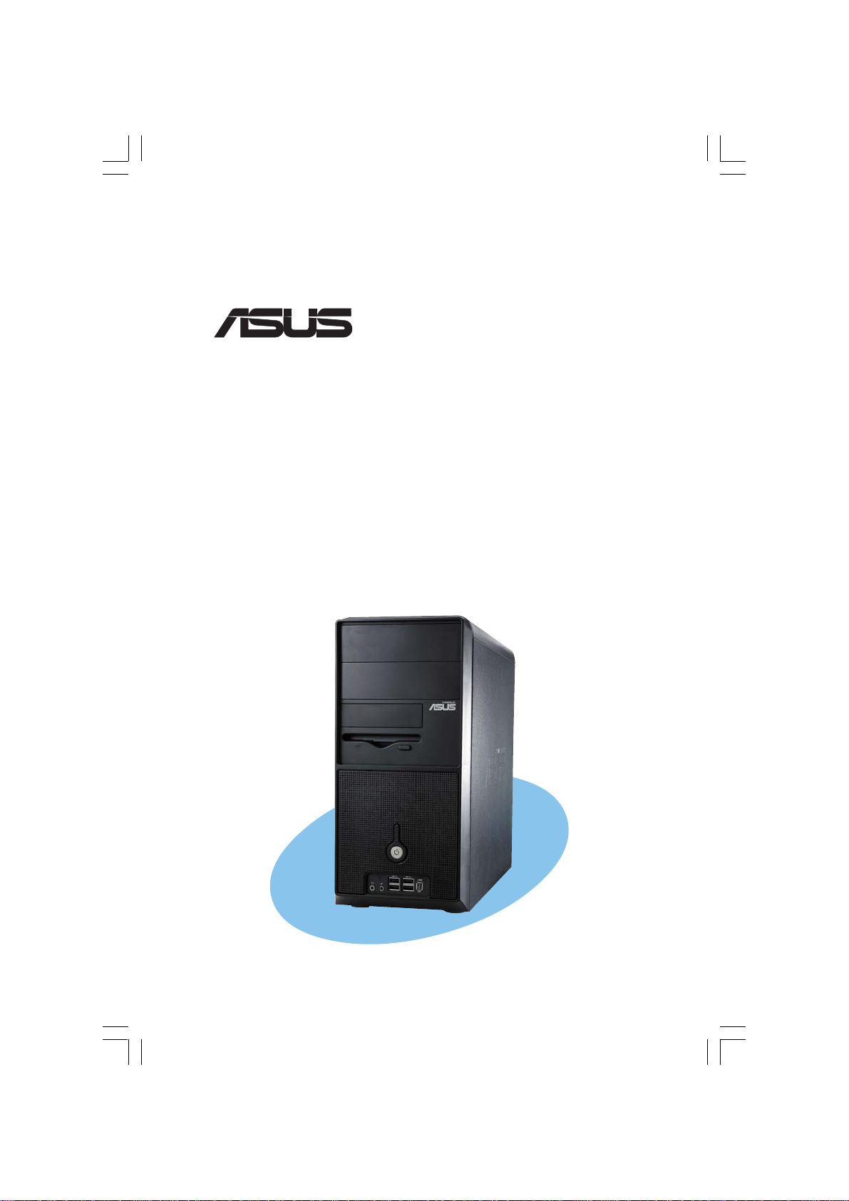
ASUS VINTAGE-PE1 User Manual
®
Vintage-PE1
Barebone System
Quick Start Guide
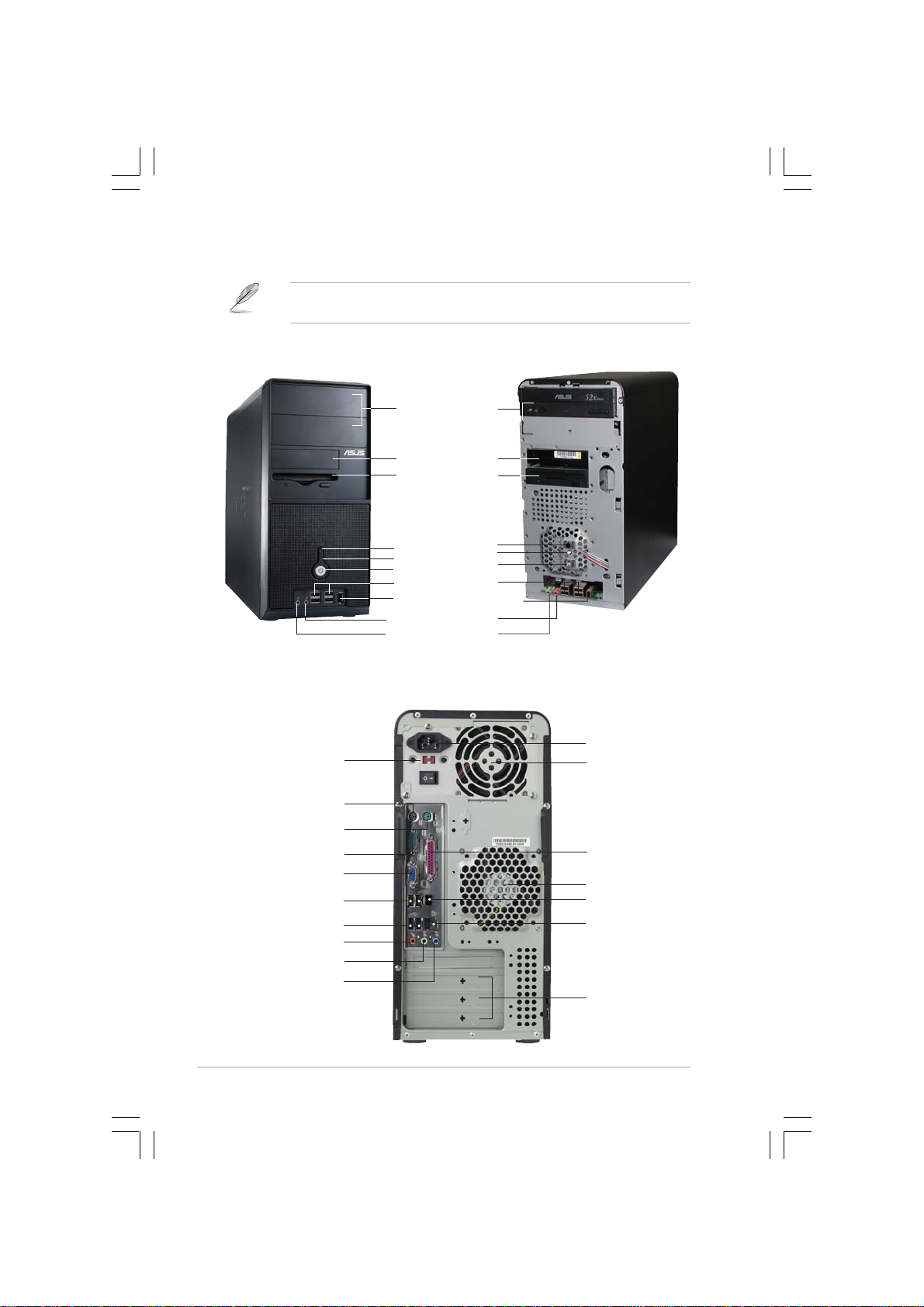
Front panel features
NOTE. NOTE.
NOTE. The photos in this guide are for reference only. For detailed
NOTE. NOTE.
information on your system’s specifications, refer to the user guide.
ExternalExternal
External
ExternalExternal
5.25-inch bays5.25-inch bays
5.25-inch bays
5.25-inch bays5.25-inch bays
(drive not(drive not
(drive not
(drive not(drive not
included)included)
included)
included)included)
HDD bayHDD bay
HDD bay
HDD bayHDD bay
FDD bayFDD bay
FDD bay
FDD bayFDD bay
(drive not(drive not
(drive not
(drive not(drive not
included)included)
included)
included)included)
Reset ButtonReset Button
Reset Button
Reset ButtonReset Button
HDD LEDHDD LED
HDD LED
HDD LEDHDD LED
Power buttonPower button
Power button
Power buttonPower button
USB 2.0 portsUSB 2.0 ports
USB 2.0 ports
USB 2.0 portsUSB 2.0 ports
IEEE port1394 portsIEEE port1394 ports
IEEE port1394 ports
IEEE port1394 portsIEEE port1394 ports
Microphone portMicrophone port
Microphone port
Microphone portMicrophone port
Headphone portHeadphone port
Headphone port
Headphone portHeadphone port
Rear panel features
Voltage selectorVoltage selector
Voltage selector
Voltage selectorVoltage selector
PS/2 keyboard portPS/2 keyboard port
PS/2 keyboard port
PS/2 keyboard portPS/2 keyboard port
PS/2 mouse portPS/2 mouse port
PS/2 mouse port
PS/2 mouse portPS/2 mouse port
Serial portSerial port
Serial port
Serial portSerial port
VGA portVGA port
VGA port
VGA portVGA port
USB 2.0 portsUSB 2.0 ports
USB 2.0 ports
USB 2.0 portsUSB 2.0 ports
USB 2.0 portsUSB 2.0 ports
USB 2.0 ports
USB 2.0 portsUSB 2.0 ports
Microphone portMicrophone port
Microphone port
Microphone portMicrophone port
Line Out portLine Out port
Line Out port
Line Out portLine Out port
Line In portLine In port
Line In port
Line In portLine In port
InternalInternal
Internal
InternalInternal
Power socketPower socket
Power socket
Power socketPower socket
Power supplyPower supply
Power supply
Power supplyPower supply
modulemodule
module
modulemodule
Parallel portParallel port
Parallel port
Parallel portParallel port
Chassis fan ventChassis fan vent
Chassis fan vent
Chassis fan ventChassis fan vent
IEEE1394IEEE1394
IEEE1394
IEEE1394IEEE1394
LL
AN (RJ-45) portAN (RJ-45) port
L
AN (RJ-45) port
LL
AN (RJ-45) portAN (RJ-45) port
Expansion slotsExpansion slots
Expansion slots
Expansion slotsExpansion slots
port port
port
port port
iiii
ii
iiii
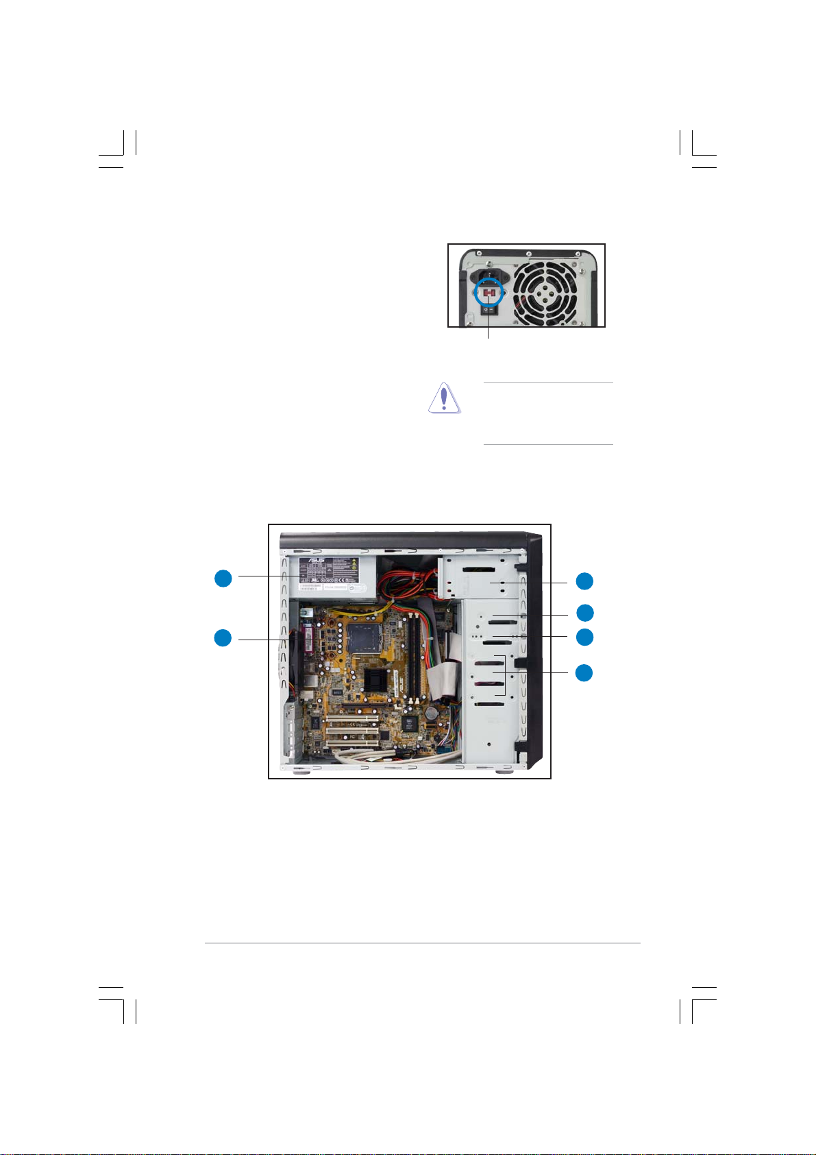
Voltage selector
The switching power supply that came
with the system has a voltage selector
switch below the power socket. Use this
switch to select the appropriate voltage
according to the voltage supply in your
area.
If the voltage supply in your area is
100-127V, set the switch to 115V.
If the voltage supply in your area is
200-240V, set the switch to 230V.
Internal components
11
1
11
115V/230V115V/230V
115V/230V
115V/230V115V/230V
Voltage selectorVoltage selector
Voltage selector
Voltage selectorVoltage selector
CAUTION. CAUTION.
CAUTION. Setting the
CAUTION. CAUTION.
switch to 115V in a 230V
environment will seriously
damage the system!
33
3
33
44
4
44
22
2
22
1. PFC power supply
2. Motherboard
3. Two 5.25” optical drive bays
4. 3.5” HDD drive bay
5. 3.5” Floppy drive bay
6. Hard disk drive bays
55
5
55
66
6
66
iiiiii
iii
iiiiii
 Loading...