

ASUS VINTAGE-AH1 User Manual
Vintage-AH1
Barebone System

E2139E2139
E2139
E2139E2139
First EditionFirst Edition
First Edition
First EditionFirst Edition
August 2005August 2005
August 2005
August 2005August 2005
Copyright © 2005 ASUSTeK COMPUTER INC. All Rights Reserved.Copyright © 2005 ASUSTeK COMPUTER INC. All Rights Reserved.
Copyright © 2005 ASUSTeK COMPUTER INC. All Rights Reserved.
Copyright © 2005 ASUSTeK COMPUTER INC. All Rights Reserved.Copyright © 2005 ASUSTeK COMPUTER INC. All Rights Reserved.
No part of this manual, including the products and software described in it, may be reproduced,
transmitted, transcribed, stored in a retrieval system, or translated into any language in any form
or by any means, except documentation kept by the purchaser for backup purposes, without the
express written permission of ASUSTeK COMPUTER INC. (“ASUS”).
Product warranty or service will not be extended if: (1) the product is repaired, modified or
altered, unless such repair, modification of alteration is authorized in writing by ASUS; or (2) the
serial number of the product is defaced or missing.
ASUS PROVIDES THIS MANUAL “AS IS” WITHOUT WARRANTY OF ANY KIND, EITHER EXPRESS OR
IMPLIED, INCLUDING BUT NOT LIMITED TO THE IMPLIED WARRANTIES OR CONDITIONS OF
MERCHANTABILITY OR FITNESS FOR A PARTICULAR PURPOSE. IN NO EVENT SHALL ASUS, ITS
DIRECTORS, OFFICERS, EMPLOYEES OR AGENTS BE LIABLE FOR ANY INDIRECT, SPECIAL,
INCIDENTAL, OR CONSEQUENTIAL DAMAGES (INCLUDING DAMAGES FOR LOSS OF PROFITS, LOSS
OF BUSINESS, LOSS OF USE OR DATA, INTERRUPTION OF BUSINESS AND THE LIKE), EVEN IF ASUS
HAS BEEN ADVISED OF THE POSSIBILITY OF SUCH DAMAGES ARISING FROM ANY DEFECT OR
ERROR IN THIS MANUAL OR PRODUCT.
SPECIFICATIONS AND INFORMATION CONTAINED IN THIS MANUAL ARE FURNISHED FOR
INFORMATIONAL USE ONLY, AND ARE SUBJECT TO CHANGE AT ANY TIME WITHOUT NOTICE, AND
SHOULD NOT BE CONSTRUED AS A COMMITMENT BY ASUS. ASUS ASSUMES NO RESPONSIBILITY
OR LIABILITY FOR ANY ERRORS OR INACCURACIES THAT MAY APPEAR IN THIS MANUAL,
INCLUDING THE PRODUCTS AND SOFTWARE DESCRIBED IN IT.
Products and corporate names appearing in this manual may or may not be registered
trademarks or copyrights of their respective companies, and are used only for identification or
explanation and to the owners’ benefit, without intent to infringe.
iiii
ii
iiii

Table of contents
Notices ............................................................................................... vii
Safety information ............................................................................. vii
About this guide ............................................................................... viii
System package contents ................................................................... x
Chapter 1: System IntroductionChapter 1: System Introduction
Chapter 1: System Introduction
Chapter 1: System IntroductionChapter 1: System Introduction
1.1 Welcome! .............................................................................. 1-2
1.2 Front panel ........................................................................... 1-2
1.3 Rear panel ............................................................................. 1-4
Voltage selector ................................................................... 1-6
1.4 Internal components ............................................................ 1-7
Chapter 2:Chapter 2:
Chapter 2:
Chapter 2:Chapter 2:
2.1 Preparation ........................................................................... 2-2
2.2 Before you proceed .............................................................. 2-2
2.3 Removing the side plates and
front cover ........................................................................... 2-3
2.4 Central Processing Unit (CPU) .............................................. 2-4
2.4.1 Overview ................................................................. 2-4
2.4.2 Installling the CPU ................................................... 2-4
2.4.3 Installing the heatsink and fan ................................ 2-6
2.5 Installing a DIMM ................................................................... 2-8
2.5.1 Memory configurations ........................................... 2-8
2.5.3 Removing a DIMM ................................................. 2-10
2.5.2 Installing a DIMM ................................................... 2-10
2.6 Expansion slots ................................................................... 2-11
2.6.1 Installing an expansion card .................................. 2-11
2.6.2 Configuring an expansion card.............................. 2-11
Basic InstallationBasic Installation
Basic Installation
Basic InstallationBasic Installation
2.6.3 PCI Express x1 slot ...............................................2-13
2.6.4 PCI slots ................................................................ 2-13
2.6.5 PCI Express x16 slot .............................................2-13
2.7 Installing an optical drive .................................................... 2-14
2.8 Installing a hard disk drive .................................................. 2-16
2.9 Installing a floppy disk drive ............................................... 2-19
2.10 Re-connecting cables ......................................................... 2-20
2.11 Replacing the side plates and front cover .......................... 2-21
iiiiii
iii
iiiiii

Table of contents
Chapter 3:Chapter 3:
Chapter 3:
Chapter 3:Chapter 3:
3.1 Installing an operating system ............................................. 3-2
3.2 Powering up .......................................................................... 3-2
3.3 Support CD information ........................................................ 3-2
3.3.1 Running the support CD ......................................... 3-3
3.3.2 Utilities menu .......................................................... 3-4
3.3.3 ASUS Contact information ...................................... 3-5
3.4 Installing the SATA controller driver .................................... 3-6
Chapter 4:Chapter 4:
Chapter 4:
Chapter 4:Chapter 4:
4.1 Introduction .......................................................................... 4-2
4.2 Motherboard layout .............................................................. 4-2
4.3 Jumpers ................................................................................ 4-3
4.4 Connectors ........................................................................... 4-6
Chapter 5:Chapter 5:
Chapter 5:
Chapter 5:Chapter 5:
5.1 Managing and updating your BIOS ........................................ 5-2
Starting upStarting up
Starting up
Starting upStarting up
Motherboard InfoMotherboard Info
Motherboard Info
Motherboard InfoMotherboard Info
BIOS InformationBIOS Information
BIOS Information
BIOS InformationBIOS Information
5.1.1 Creating a bootable floppy disk .............................. 5-2
5.1.2 ASUS EZ Flash utility .............................................. 5-3
5.1.3 AFUDOS utility ........................................................ 5-4
5.1.4 ASUS CrashFree BIOS 2 utility ................................ 5-6
5.1.5 ASUS Update utility ................................................ 5-8
5.2 BIOS setup program ........................................................... 5-11
5.2.1 BIOS menu screen ................................................. 5-12
5.2.2 Menu bar ............................................................... 5-12
5.2.3 Navigation keys .................................................... 5-12
5.2.4 Menu items ........................................................... 5-13
5.2.5 Sub-menu items ................................................... 5-13
5.2.6 Configuration fields .............................................. 5-13
5.2.7 Pop-up window ..................................................... 5-13
5.2.8 Scroll bar .............................................................. 5-13
5.2.9 General help .......................................................... 5-13
5.3 Main menu .......................................................................... 5-14
iviv
iv
iviv
5.3.1 System Time ......................................................... 5-14
5.3.2 System Date ......................................................... 5-14

Table of contents
5.3.3 Legacy Diskette A ................................................5-14
5.3.4 Primary and Secondary IDE Master/Slave ............. 5-15
5.3.5 System Information ..............................................5-16
5.4 Advanced menu .................................................................. 5-17
5.4.1 CPU Configuration ................................................. 5-17
5.4.2 Chipset ................................................................. 5-19
5.4.3 Onboard Devices Configuration ............................5-26
5.4.4 PCI PnP ................................................................. 5-28
5.4.5 JumperFree Configuration .................................... 5-29
5.4.6 Instant Music Configuration ..................................5-29
5.5 Power menu ........................................................................ 5-30
5.5.1 Suspend Mode ...................................................... 5-30
5.5.2 Repost Video on S3 Resume ................................ 5-30
5.5.3 ACPI 2.0 Support .................................................. 5-30
5.5.4 ACPI APIC Support ................................................ 5-30
5.5.5 APM Configuration ................................................ 5-31
5.5.6 Hardware Monitor ................................................. 5-32
5.6 Boot menu .......................................................................... 5-34
5.6.1 Boot Device Priority .............................................. 5-34
5.6.2 Boot Settings Configuration ................................. 5-34
5.6.3 Security ................................................................ 5-36
5.7 Exit menu ........................................................................... 5-38
vv
v
vv

Notices
Federal Communications Commission StatementFederal Communications Commission Statement
Federal Communications Commission Statement
Federal Communications Commission StatementFederal Communications Commission Statement
This device complies with Part 15 of the FCC Rules. Operation is subject to
the following two conditions:
•
This device may not cause harmful interference, and
•
This device must accept any interference received including interference
that may cause undesired operation.
This equipment has been tested and found to comply with the limits for a
Class B digital device, pursuant to Part 15 of the FCC Rules. These limits are
designed to provide reasonable protection against harmful interference in a
residential installation. This equipment generates, uses and can radiate radio
frequency energy and, if not installed and used in accordance with
manufacturer’s instructions, may cause harmful interference to radio
communications. However, there is no guarantee that interference will not
occur in a particular installation. If this equipment does cause harmful
interference to radio or television reception, which can be determined by
turning the equipment off and on, the user is encouraged to try to correct
the interference by one or more of the following measures:
•
Reorient or relocate the receiving antenna.
•
Increase the separation between the equipment and receiver.
•
Connect the equipment to an outlet on a circuit different from that to
which the receiver is connected.
•
Consult the dealer or an experienced radio/TV technician for help.
WARNING!WARNING!
WARNING! The use of shielded cables for connection of the monitor to
WARNING!WARNING!
the graphics card is required to assure compliance with FCC regulations.
Changes or modifications to this unit not expressly approved by the
party responsible for compliance could void the user’s authority to
operate this equipment.
Canadian Department of Communications StatementCanadian Department of Communications Statement
Canadian Department of Communications Statement
Canadian Department of Communications StatementCanadian Department of Communications Statement
This digital apparatus does not exceed the Class B limits for radio noise
emissions from digital apparatus set out in the Radio Interference
Regulations of the Canadian Department of Communications.
This class B digital apparatus complies with Canadian ICES-003.This class B digital apparatus complies with Canadian ICES-003.
This class B digital apparatus complies with Canadian ICES-003.
This class B digital apparatus complies with Canadian ICES-003.This class B digital apparatus complies with Canadian ICES-003.
vivi
vi
vivi

Safety information
Electrical safetyElectrical safety
Electrical safety
Electrical safetyElectrical safety
•
To prevent electrical shock hazard, disconnect the power cable from the
electrical outlet before relocating the system.
•
When adding or removing devices to or from the system, ensure that the
power cables for the devices are unplugged before the signal cables are
connected.
•
If the power supply is broken, do not try to fix it by yourself. Contact a
qualified service technician or your retailer.
Operation safetyOperation safety
Operation safety
Operation safetyOperation safety
•
Before installing devices into the system, carefully read all the
documentation that came with the package.
•
Before using the product, make sure all cables are correctly connected
and the power cables are not damaged. If you detect any damage,
contact your dealer immediately.
•
To avoid short circuits, keep paper clips, screws, and staples away from
connectors, slots, sockets and circuitry.
•
Avoid dust, humidity, and temperature extremes. Do not place the
product in any area where it may become wet. Place the product on a
stable surface.
•
If you encounter technical problems with the product, contact a qualified
service technician or your retailer.
Lithium-Ion Battery WarningLithium-Ion Battery Warning
Lithium-Ion Battery Warning
Lithium-Ion Battery WarningLithium-Ion Battery Warning
CAUTIONCAUTION
CAUTION: Danger of explosion if battery is incorrectly replaced.
CAUTIONCAUTION
Replace only with the same or equivalent type recommended by the
manufacturer. Dispose of used batteries according to the
manufacturerís instructions.
VORSICHTVORSICHT
VORSICHT: Explosionsgetahr bei unsachgemäßen Austausch der
VORSICHTVORSICHT
Batterie. Ersatz nur durch denselben oder einem vom Hersteller
empfohlenem ähnljchen Typ. Entsorgung gebrauchter Batterien nach
Angaben des Herstellers.
LASER PRODUCT WARNINGLASER PRODUCT WARNING
LASER PRODUCT WARNING
LASER PRODUCT WARNINGLASER PRODUCT WARNING
CLASS 1 LASER PRODUCTCLASS 1 LASER PRODUCT
CLASS 1 LASER PRODUCT
CLASS 1 LASER PRODUCTCLASS 1 LASER PRODUCT
viivii
vii
viivii

About this guide
AudienceAudience
Audience
AudienceAudience
This guide provides general information and installation instructions about
the ASUS Vintage-AH1 barebone system. This guide is intended for
experienced users and integrators with hardware knowledge of personal
computers.
How this guide is organizedHow this guide is organized
How this guide is organized
How this guide is organizedHow this guide is organized
This guide contains the following parts:
1.1.
Chapter 1: System introductionChapter 1: System introduction
1.
Chapter 1: System introduction
1.1.
Chapter 1: System introductionChapter 1: System introduction
This chapter gives a general description of the ASUS Vintage-AH1.
The chapter lists the system features, including introduction on the
front and rear panel, and internal components.
2.2.
Chapter 2: Basic installationChapter 2: Basic installation
2.
Chapter 2: Basic installation
2.2.
Chapter 2: Basic installationChapter 2: Basic installation
This chapter provides step-by-step instructions on how to install
components in the system.
3.3.
Chapter 3: Starting upChapter 3: Starting up
3.
Chapter 3: Starting up
3.3.
Chapter 3: Starting upChapter 3: Starting up
This chapter helps you power up the system and install drivers and
utilities from the support CD.
4.4.
Chapter 4: Motherboard informationChapter 4: Motherboard information
4.
Chapter 4: Motherboard information
4.4.
Chapter 4: Motherboard informationChapter 4: Motherboard information
This chapter gives information about the motherboard that comes
with the system. This chapter includes the motherboard layout,
jumper settings, and connector locations.
5.5.
Chapter 5: BIOS informationChapter 5: BIOS information
5.
Chapter 5: BIOS information
5.5.
Chapter 5: BIOS informationChapter 5: BIOS information
This chapter tells how to change system settings through the BIOS
Setup menus and describes the BIOS parameters.
viiiviii
viii
viiiviii

Conventions used in this guideConventions used in this guide
Conventions used in this guide
Conventions used in this guideConventions used in this guide
WARNING: WARNING:
WARNING: Information to prevent injury to yourself when
WARNING: WARNING:
trying to complete a task.
CAUTION: CAUTION:
CAUTION: Information to prevent damage to the components
CAUTION: CAUTION:
when trying to complete a task.
IMPORTANT: IMPORTANT:
IMPORTANT: Instructions that you MUST follow to complete a
IMPORTANT: IMPORTANT:
task.
NOTE: NOTE:
NOTE: Tips and additional information to aid in completing a
NOTE: NOTE:
task.
Where to find more informationWhere to find more information
Where to find more information
Where to find more informationWhere to find more information
Refer to the following sources for additional information and for product
and software updates.
1.1.
ASUS WebsitesASUS Websites
1.
ASUS Websites
1.1.
ASUS WebsitesASUS Websites
The ASUS websites worldwide provide updated information on ASUS
hardware and software products. Refer to the ASUS contact
information.
2.2.
Optional DocumentationOptional Documentation
2.
Optional Documentation
2.2.
Optional DocumentationOptional Documentation
Your product package may include optional documentation, such as
warranty flyers, that may have been added by your dealer. These
documents are not part of the standard package.
ixix
ix
ixix
System package contents
Check your Vintage-AH1 system package for the following items.
If any of the items is damaged or missing, contact your retailer
immediately.
Item descriptionItem description
Item description
Item descriptionItem description
1.1.
ASUS Vintage-AH1 barebone systemASUS Vintage-AH1 barebone system
1.
ASUS Vintage-AH1 barebone system with
1.1.
ASUS Vintage-AH1 barebone systemASUS Vintage-AH1 barebone system
• ASUS motherboard
• 300 W PFC power supply unit
• ASUS chassis
2.2.
CableCable
2.
Cable
2.2.
CableCable
• AC power cable
3.3.
Support CDSupport CD
3.
Support CD
3.3.
Support CDSupport CD
4.4.
User guideUser guide
4.
User guide
4.4.
User guideUser guide
xx
x
xx
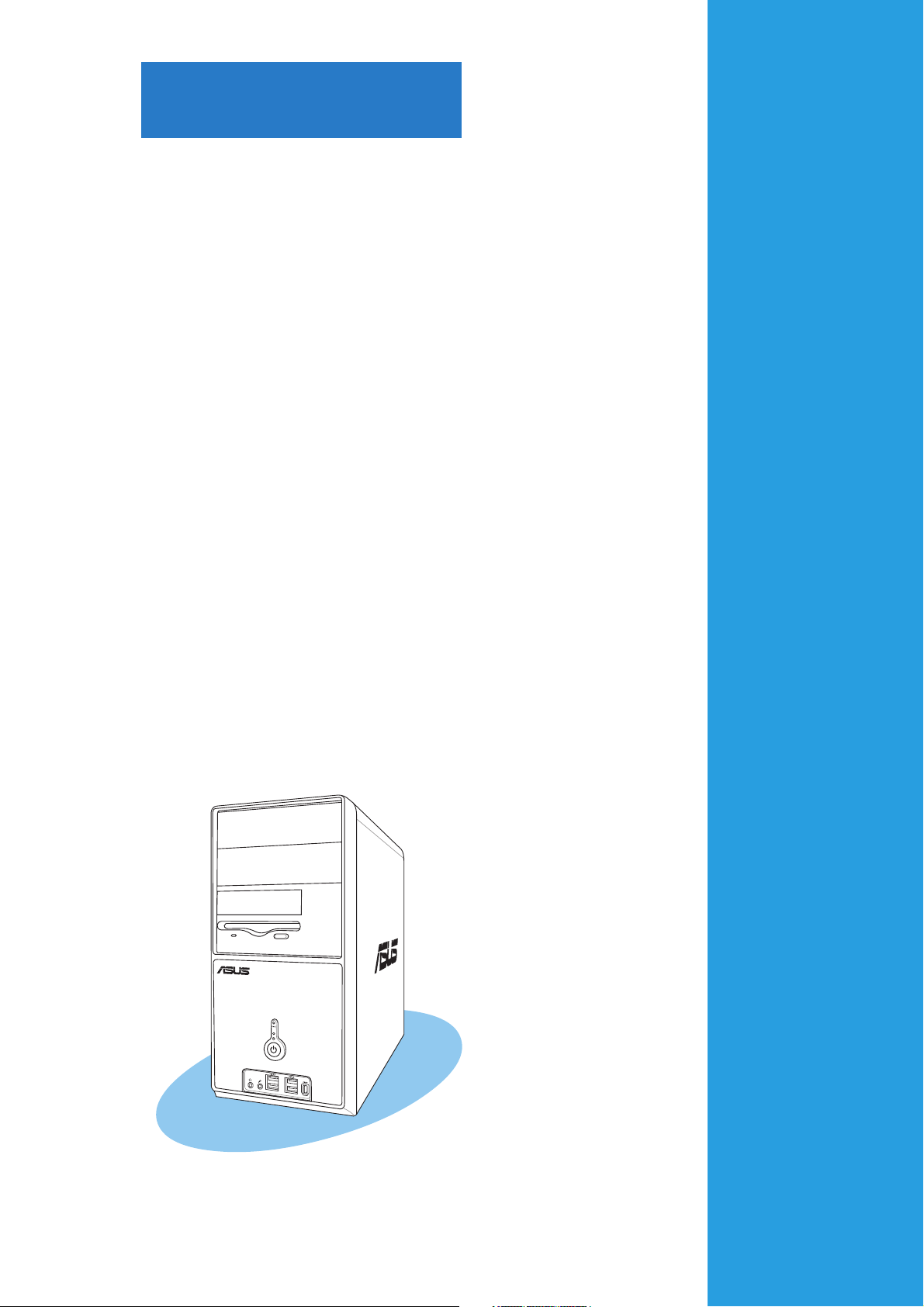
Chapter 1
This chapter gives a general
description of the ASUS
Vintage-AH1. The chapter lists the
system features including
introduction on the front and rear
panel, and internal components.
ASUS Vintage-AH1ASUS Vintage-AH1
ASUS Vintage-AH1
ASUS Vintage-AH1ASUS Vintage-AH1
System introduction
1.1 Welcome!
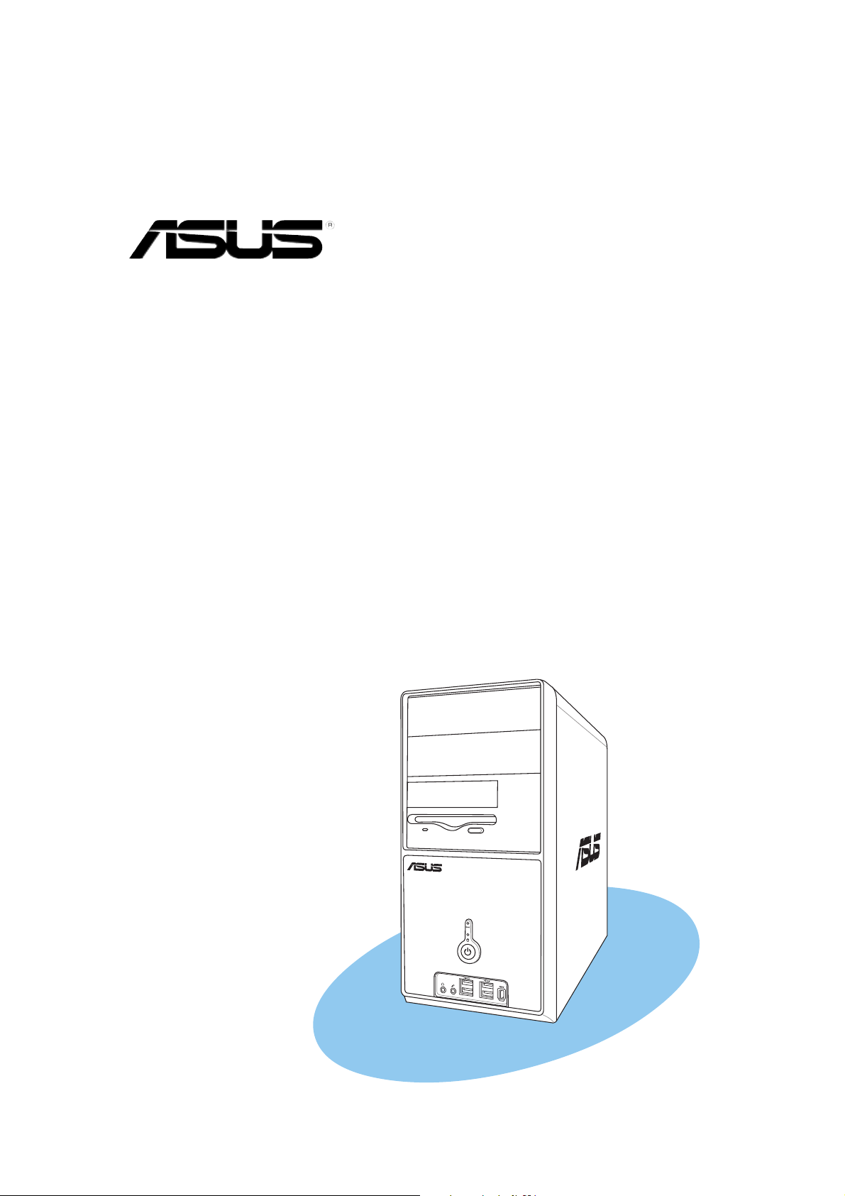
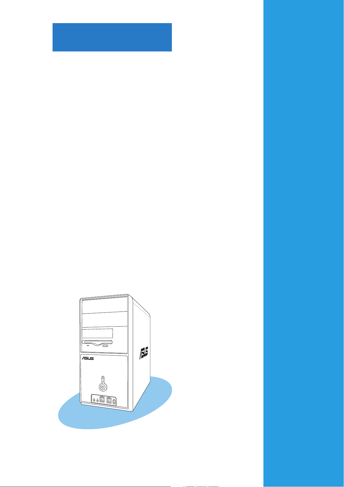
Thank you for choosing the ASUS Vintage-AH1!
The ASUS Vintage-AH1 is an all-in-one barebone system with a versatile
home entertainment feature.
The system comes in a stylish mini-tower casing and powered by the ASUS
motherboard that supports the AMD Athlon™ 64 and Athlon™ 64FX
desktop processors.
The system supports up to 4 GB of system memory using DDR400/333
DIMMs, high-resolution graphics via integrated graphics controller or PCI
Express x16 slot, Serial ATA, USB 2.0, and 8-channel audio features the
system takes you ahead in the world of power computing.
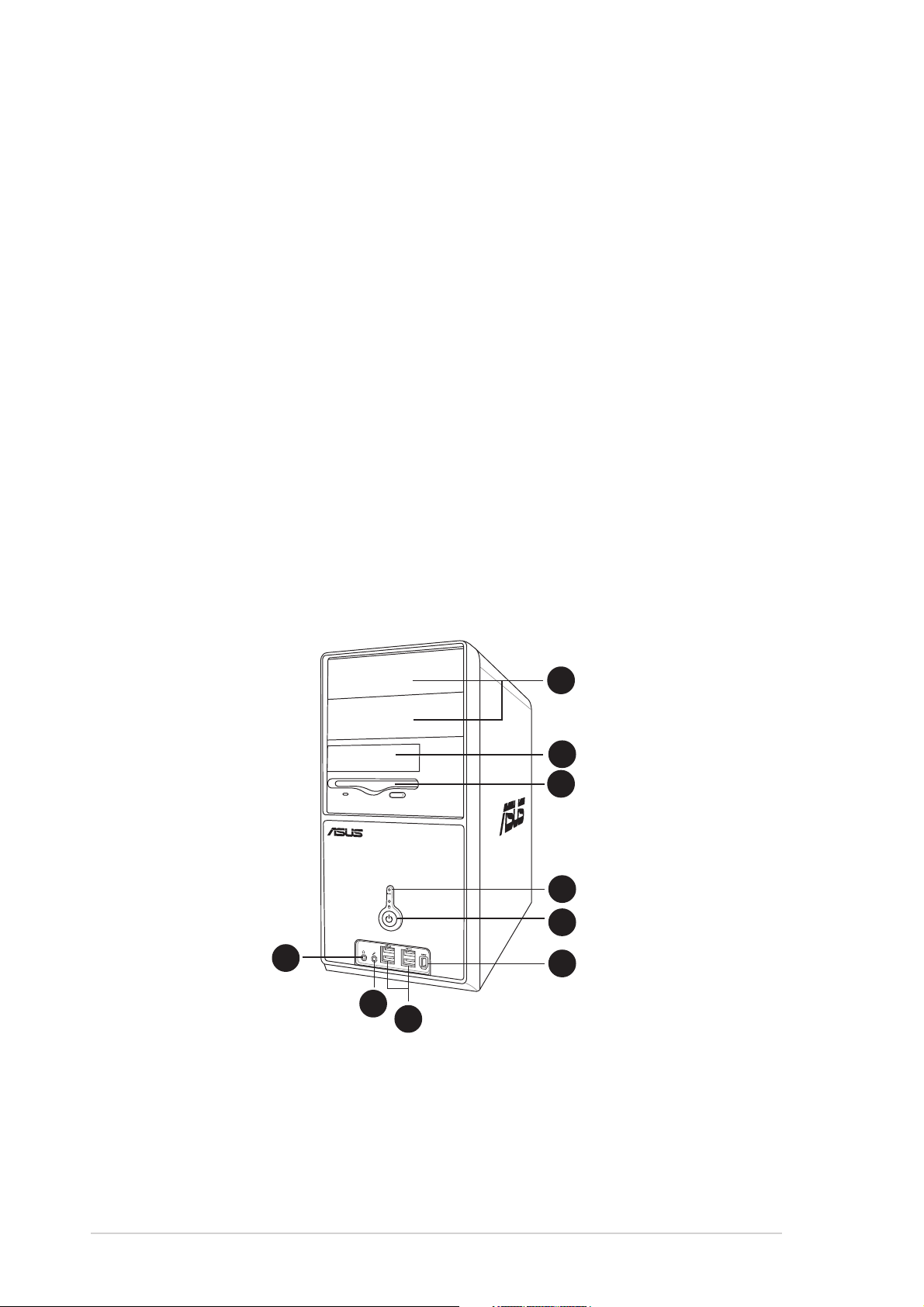
1.2 Front panel
The front panel includes the optical drive bays, floppy disk drive slot, power
button, and several I/O ports are located at the front panel.
1
2
3
4
5
9
8
7
6
1-21-2
1-2
1-21-2
Chapter 1: System introductionChapter 1: System introduction
Chapter 1: System introduction
Chapter 1: System introductionChapter 1: System introduction

1.1.
Two empty 5.25-inch baysTwo empty 5.25-inch bays
1.
Two empty 5.25-inch bays. These bays are for IDE optical drives.
1.1.
Two empty 5.25-inch baysTwo empty 5.25-inch bays
2.2.
Hard disk drive bayHard disk drive bay
2.
Hard disk drive bay. This door covers a hard disk drive.
2.2.
Hard disk drive bayHard disk drive bay
3.3.
Floppy drive slotFloppy drive slot
3.
Floppy drive slot. This slot is for the 3.5-inch floppy disk drive.
3.3.
Floppy drive slotFloppy drive slot
(The floppy disk drive is included in the package.)
4.4.
Reset buttonReset button
4.
Reset button. Press this button to reboot the system without
4.4.
Reset buttonReset button
turning off the power.
5.5.
Power buttonPower button
5.
Power button. Press this button to turn the system on.
5.5.
Power buttonPower button
6.6.
IEEE 1394 portIEEE 1394 port
6.
IEEE 1394 port. This 6-pin IEEE 1394a port provides high-speed
6.6.
IEEE 1394 portIEEE 1394 port
connectivity for audio/video devices, storage peripherals, PCs, or
protable devices.
7.7.
USB 2.0 portsUSB 2.0 ports
7.
USB 2.0 ports. These Universal Serial Bus 2.0 (USB 2.0) ports are
7.7.
USB 2.0 portsUSB 2.0 ports
available for connecting USB 2.0 devices such as a mouse, printer,
scanner, camera, PDA, and others.
8.8.
Microphone portMicrophone port
8.
Microphone port. This Mic (pink) port connects a microphone.
8.8.
Microphone portMicrophone port
9.9.
Headphone portHeadphone port
9.
Headphone port. This Line In (green) port connects a headphone
9.9.
Headphone portHeadphone port
with a stereo mini-plug.
ASUS Vintage-AH1ASUS Vintage-AH1
ASUS Vintage-AH1
ASUS Vintage-AH1ASUS Vintage-AH1
1-31-3
1-3
1-31-3
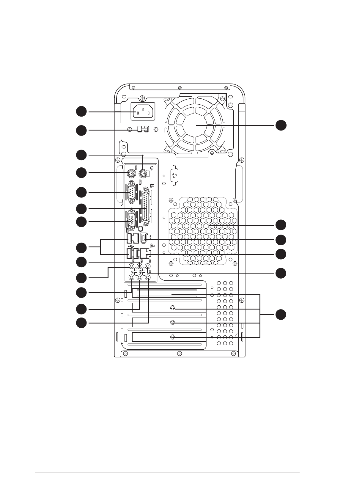
1.3 Rear panel
The system rear panel includes the power connector and several I/O ports
that allow convenient connection of devices.
1
2
3
4
5
6
7
8
9
10
11
14
15
16
BASS
MIC IN
REAR
C T R
S P K
S P K
SIDE
FRONT
LINE
IN
17
18
1-41-4
1-4
1-41-4
12
13
1.1.
Power connector.Power connector.
1.
Power connector. This connector is for the power cable and plug.
1.1.
Power connector.Power connector.
2.2.
Voltage selector.Voltage selector.
2.
Voltage selector. This switch allows you to adjust the system
2.2.
Voltage selector.Voltage selector.
input voltage according to the voltage supply in your area. See the
“Voltage selector” section on page 1-6 before adjusting this switch.
3.3.
PS/2 mouse portPS/2 mouse port
3.
PS/2 mouse port. This green 6-pin connector is for a PS/2 mouse.
3.3.
PS/2 mouse portPS/2 mouse port
4.4.
PS/2 keyboard portPS/2 keyboard port
4.
PS/2 keyboard port. This purple 6-pin connector is for a
4.4.
PS/2 keyboard portPS/2 keyboard port
PS/2 keyboard.
5.5.
Serial portSerial port
5.
Serial port . This port connects a mouse, modem, or other devices
5.5.
Serial portSerial port
that conforms with serial specification.
Chapter 1: System introductionChapter 1: System introduction
Chapter 1: System introduction
Chapter 1: System introductionChapter 1: System introduction
19
6.6.
Parallel port.Parallel port.
6.
Parallel port. This 25-pin port connects a printer, scanner, or other
6.6.
Parallel port.Parallel port.
devices.
7.7.
VGA port. VGA port.
7.
VGA port. This port connects a VGA monitor.
7.7.
VGA port. VGA port.
8.8.
USB 2.0 ports 1, 2, 3 and 4.USB 2.0 ports 1, 2, 3 and 4.
8.
USB 2.0 ports 1, 2, 3 and 4. These 4-pin Universal Serial Bus
8.8.
USB 2.0 ports 1, 2, 3 and 4.USB 2.0 ports 1, 2, 3 and 4.
(USB) ports are available for connecting USB 2.0 devices.
9.9.
Side Speaker Out port (black).Side Speaker Out port (black).
9.
Side Speaker Out port (black). This port connects the side
9.9.
Side Speaker Out port (black).Side Speaker Out port (black).
speakers in an 8-channel audio configuration.
10.10.
Rear Speaker Out port (orange).Rear Speaker Out port (orange).
10.
Rear Speaker Out port (orange). This port connects the rear
10.10.
Rear Speaker Out port (orange).Rear Speaker Out port (orange).
speakers on a 4-channel, 6-channel, or 8-channel audio configuration.
11.11.
Microphone port (pink). Microphone port (pink).
11.
Microphone port (pink). This port connects a microphone.
11.11.
Microphone port (pink). Microphone port (pink).
12.12.
Line Out port (lime).Line Out port (lime).
12.
Line Out port (lime). This port connects a headphone or a
12.12.
Line Out port (lime).Line Out port (lime).
speaker. In 4-channel, 6-channel, and 8-channel configuration, the
function of this port becomes Front Speaker Out.
13.13.
Line In port (light blue).Line In port (light blue).
13.
Line In port (light blue). This port connects the tape, CD, DVD
13.13.
Line In port (light blue).Line In port (light blue).
player, or other audio sources.
14.14.
Power supply unit fan vent.Power supply unit fan vent.
14.
Power supply unit fan vent. This vent is for the PSU fan that
14.14.
Power supply unit fan vent.Power supply unit fan vent.
provides ventilation inside the power supply unit.
15.15.
Chassis fan vent.Chassis fan vent.
15.
Chassis fan vent. This vent is for the fan that provides ventilation
15.15.
Chassis fan vent.Chassis fan vent.
inside the system chassis.
16.16.
IEEE 1394a port. IEEE 1394a port.
16.
IEEE 1394a port. This 6-pin IEEE 1394 port provides high-speed
16.16.
IEEE 1394a port. IEEE 1394a port.
connectivity for audio/video devices, storage peripherals, PCs, or
portable devices.
17.17.
LAN (RJ-45) port. LAN (RJ-45) port.
17.
LAN (RJ-45) port. This port allows Gigabit connection to a Local
17.17.
LAN (RJ-45) port. LAN (RJ-45) port.
Area Network (LAN) through a network hub.
18.18.
Center/Subwoofer port (gray).Center/Subwoofer port (gray).
18.
Center/Subwoofer port (gray). This port connects the center/
18.18.
Center/Subwoofer port (gray).Center/Subwoofer port (gray).
subwoofer speakers.
19.19.
Expansion slot coversExpansion slot covers
19.
Expansion slot covers. Remove these cover when installing
19.19.
Expansion slot coversExpansion slot covers
expansion cards.
Refer to the audio configuration table below for the function of the
audio ports in 2, 4, 6, or 8-channel configuration.
Audio 2, 4, 6, or 8-channel configurationAudio 2, 4, 6, or 8-channel configuration
Audio 2, 4, 6, or 8-channel configuration
Audio 2, 4, 6, or 8-channel configurationAudio 2, 4, 6, or 8-channel configuration
PortPort
Port
PortPort
HeadsetHeadset
Headset
HeadsetHeadset
2-channel2-channel
2-channel
2-channel2-channel
4-channel4-channel
4-channel
4-channel4-channel
6-channel6-channel
6-channel
6-channel6-channel
8-channel8-channel
8-channel
8-channel8-channel
Light Blue Line In Line In Line In Line In
Lime Line Out Front Speaker Out Front Speaker Out Front Speaker Out
Pink Mic In Mic In Mic In Mic In
Orange • Rear Speaker Out Rear Speaker Out Rear Speaker Out
Black •• •Side Speaker Out
Gray ••Center/Subwoofer Center/Subwoofer
ASUS Vintage-AH1ASUS Vintage-AH1
ASUS Vintage-AH1
ASUS Vintage-AH1ASUS Vintage-AH1
1-51-5
1-5
1-51-5
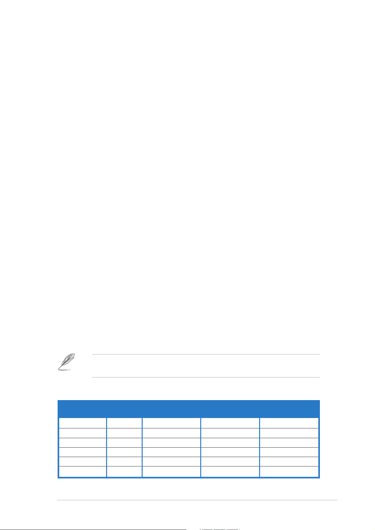
Voltage selectorVoltage selector
Voltage selector
Voltage selectorVoltage selector
The PSU has a 115 V/230 V voltage selector switch located beside the
power connector. Use this switch to select the appropriate system input
voltage according to the voltage supply in your area.
If the voltage supply in your area is 100-127 V, set this switch to 115 V.
If the voltage supply in your area is 200-240 V, set this switch to 230 V.
115V/230V115V/230V
115V/230V
115V/230V115V/230V
Voltage selectorVoltage selector
Voltage selector
Voltage selectorVoltage selector
Setting the switch to 115V in a 230V environment or 230V in a 115V
environment will seriously damage the system!
1-61-6
1-6
1-61-6
Chapter 1: System introductionChapter 1: System introduction
Chapter 1: System introduction
Chapter 1: System introductionChapter 1: System introduction
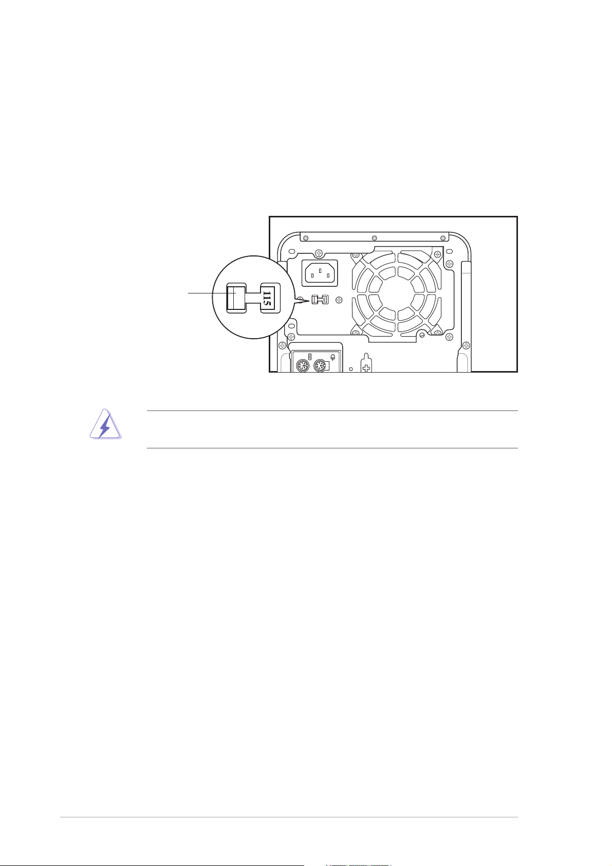
1.4 Internal components
The illustration below is the internal view of the system when you remove
the top cover and the power supply unit. The installed components are
labeled for your reference. Proceed to Chapter 2 for instructions on
installing additional system components.
11
1
11
22
2
22
KBPWR
PS/2KBMS
T: Mouse
B: Keyboard
COM2
VGA
66
6
66
11
1
11
F_USB12
LAN_USB34
Top:Rear Speaker Out
Center:
Side Speaker Out
Below:
Center/Subwoofer
Top:Line In
Center:Line Out
Below:Mic In
44
4
44
FP_AUDIO
88E8053
ATX12V
PARALLEL PORT
USBPW12
USBPW34
PCIEX1_1
1010
10
1010
ALC880
SPDIF_OUT
CD
GAME
PCIEX16
PCI1
11
1
11
PCI2
FLOPPY
55
5
55
ATI
RS482
55
5
55
1212
12
1212
Socket 939
1111
11
1111
VIA
IE1394_1
CPU_FAN
DDR DIMM_A2 (64 bit,184-pin module)
DDR DIMM_A1 (64 bit,184-pin module)
CHA_FAN
®
ULIM1573
VT6307
USBPW78
USBPW56
USB56
USB78
I/O
Super
44
4
44
ATXPWR
77
7
77
PRI_IDE
SEC_IDE
DDR DIMM_B2 (64 bit,184-pin module)
DDR DIMM_B1 (64 bit,184-pin module)
11
33
1
3
11
33
CR2032 3V
Lithium Cell
CMOS Power
CLRTC
SATA3
SATA4
SATA1
SATA2
11
66
1
6
11
66
4M
FWH
BIOS
SB_PWR
F_PANEL
PANEL
33
3
33
99
9
99
88
8
88
1. Power supply unit
2. 5.25-inch drive bay
3. Floppy disk drive bay
4. ATX power supply connector
5. Socket 939 for AMD Athlon™
64/AMD Athlon™ 64FX CPUs
6. Chassis fan
7. DIMM sockets
8. Hard disk drive bays
ASUS Vintage-AH1ASUS Vintage-AH1
ASUS Vintage-AH1
ASUS Vintage-AH1ASUS Vintage-AH1
9. Front panel cover
10. PCI Express x1 slot
11. ASUS motherboard
12. PCI Express x16 slot
13. IDE connectors
14. Expansion card slots
15. PCI slots
16. Serial ATA connectors
1-71-7
1-7
1-71-7

1-81-8
1-8
1-81-8
Chapter 1: System introductionChapter 1: System introduction
Chapter 1: System introduction
Chapter 1: System introductionChapter 1: System introduction
Chapter 2
This chapter provides step-by-step
instructions on how to install
components in the system.
ASUS Vintage-AH1ASUS Vintage-AH1
ASUS Vintage-AH1
ASUS Vintage-AH1ASUS Vintage-AH1
Basic installation
2.1 Preparation
Before you proceed, make sure that you have all the components you plan
to install in the system.
Basic components to installBasic components to install
Basic components to install
Basic components to installBasic components to install
1. Central processing unit (CPU)
2. DDR Dual Inline Memory Module (DIMM)
3. Expansion card(s)
4. Hard disk drive
5. Optical drive
6. Floppy disk drive
ToolTool
Tool
ToolTool
Phillips (cross) screw driver
2.2 Before you proceed
Take note of the following precautions before you install components into
the system.
•
Use a grounded wrist strap or touch a safely grounded object or a
metal object, such as the power supply case, before handling
components to avoid damaging them due to static electricity.
•
Hold components by the edges to avoid touching the ICs on them.
•
Whenever you uninstall any component, place it on a grounded
antistatic pad or in the bag that came with the component.
The motherboard comes with an onboard standby power LED. This LED
lights up to indicate that the system is ON, in sleep mode or in soft-off
mode, and not powered OFF. Unplug the power cable from the power outlet
and make sure that the standby power LED is OFF before installing any
system component.
2-22-2
2-2
2-22-2
Onboard LED
SB_PWR
®
ON
Standby
Power
OFF
Powered
Off
Chapter 2: Basic installationChapter 2: Basic installation
Chapter 2: Basic installation
Chapter 2: Basic installationChapter 2: Basic installation
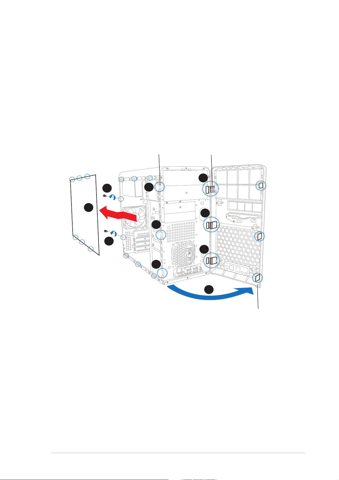
2.3 Removing the side plates and
front cover
The system has two chassis side plates, each one secured by two screws
located on the rear panel.
To remove the chassis side plate:
1. Turn each screw counterclockwise to release the side cover. Set the
screws aside.
2. Slide the side panel for about half an inch toward the rear until it
disengages from the chassis.
Steel railingSteel railing
Steel railing
Steel railingSteel railing
1
4
Hinge-like tabHinge-like tab
Hinge-like tab
Hinge-like tabHinge-like tab
6
2
6
4
1
6
4
5
Side lock tabSide lock tab
Side lock tab
Side lock tabSide lock tab
3. Repeat steps 1 and 2 to remove the other side plate cover.
4. Release the side lock tabs from the steel railing.
5. Swing the left edge of the front panel outward.
6. Unhook the hinge-like tabs from the holes on the right side of the
front panel to completely detach the front panel assembly from the
chassis.
ASUS Vintage-AH1ASUS Vintage-AH1
ASUS Vintage-AH1
ASUS Vintage-AH1ASUS Vintage-AH1
2-32-3
2-3
2-32-3
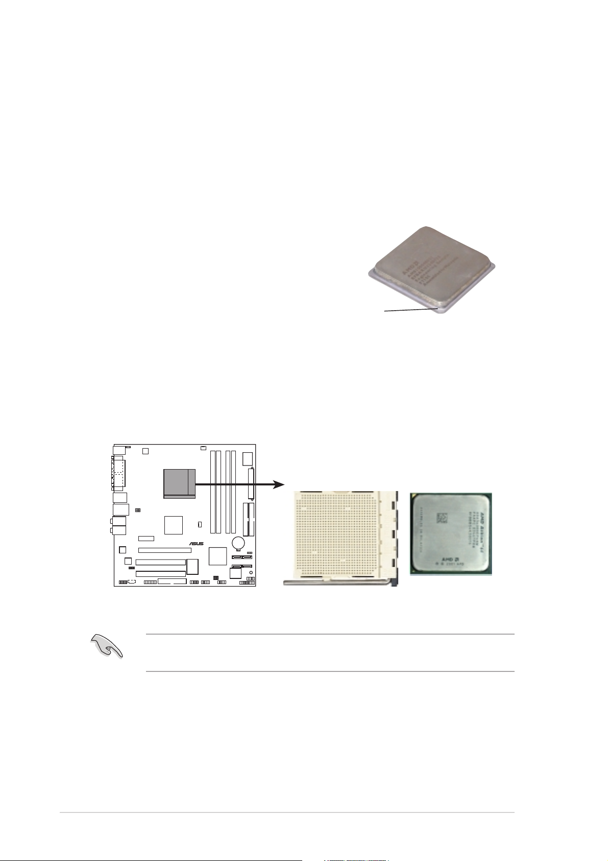
2.4 Central Processing Unit (CPU)
2.4.12.4.1
2.4.1
2.4.12.4.1
The motherboard comes with a surface mount 939-pin Zero Insertion Force
(ZIF) socket designed for the AMD Athlon™ 64FX or AMD Athlon™ 64
processor.
The 128-bit-wide data paths of these processors can run applications
faster than processors with only 32-bit or 64-bit wide data paths.
Take note of the marked corner (with
gold triangle) on the CPU. This mark
should match a specific corner on the
socket to ensure correct installation.
2.4.22.4.2
2.4.2
2.4.22.4.2
To install a CPU:
OverviewOverview
Overview
OverviewOverview
Installling the CPUInstallling the CPU
Installling the CPU
Installling the CPUInstallling the CPU
Gold triangle
1. Locate the CPU socket on the motherboard.
®
CPU Socket 939
Before installing the CPU, make sure that the socket box is facing
towards you and the load lever is on your left.
2-42-4
2-4
2-42-4
Chapter 2: Basic installationChapter 2: Basic installation
Chapter 2: Basic installation
Chapter 2: Basic installationChapter 2: Basic installation
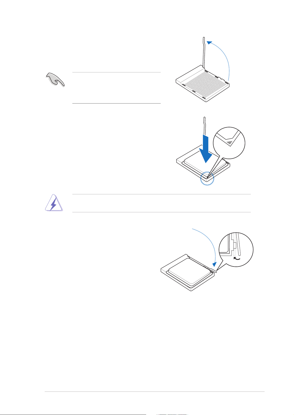
2. Unlock the socket by pressing the
lever sideways, then lift it up to a
90°-100° angle.
Make sure that the socket lever is
lifted up to 90°-100° angle,
otherwise the CPU does not fit in
completely.
3. Position the CPU above the socket
such that the CPU corner with the
gold triangle matches the socket
corner with a small triangle.
4. Carefully insert the CPU into the
socket until it fits in place.
The CPU fits only in one correct orientation. DO NOT force the CPU into
the socket to prevent bending the pins and damaging the CPU!
5. When the CPU is in place, push down
the socket lever to secure the CPU.
The lever clicks on the side tab to
indicate that it is locked.
ASUS Vintage-AH1ASUS Vintage-AH1
ASUS Vintage-AH1
ASUS Vintage-AH1ASUS Vintage-AH1
2-52-5
2-5
2-52-5
2.4.32.4.3
2.4.3
2.4.32.4.3
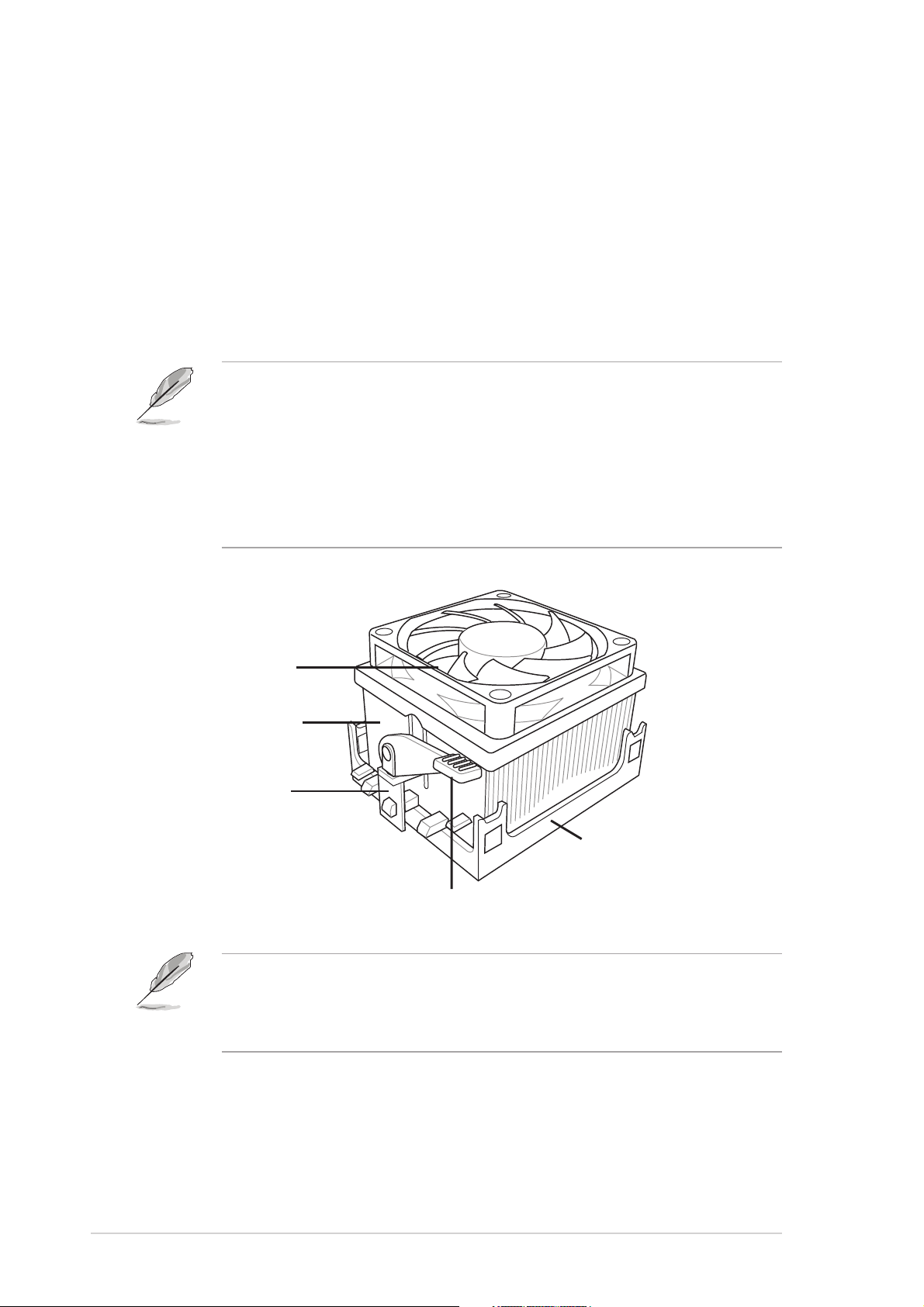
Installing the heatsink and fanInstalling the heatsink and fan
Installing the heatsink and fan
Installing the heatsink and fanInstalling the heatsink and fan
The AMD Athlon™ 64FX or AMD Athlon 64™ processor require a specially
designed heatsink and fan assembly to ensure optimum thermal condition
and performance.
Follow these steps to install the CPU heatsink and fan.
1. Place the heatsink on top of the installed CPU, making sure that the
heatsink fits properly on the retention module base.
• The retention module base is already installed on the motherboard
upon purchase.
• You do not have to remove the retention module base when
installing the CPU or installing other motherboard components.
• If you purchased a separate CPU heatsink and fan assembly, make
sure that a Thermal Interface Material is properly applied to the CPU
heatsink or CPU before you install the heatsink and fan assembly.
CPU FanCPU Fan
CPU Fan
CPU FanCPU Fan
CPU HeatsinkCPU Heatsink
CPU Heatsink
CPU HeatsinkCPU Heatsink
Retention bracketRetention bracket
Retention bracket
Retention bracketRetention bracket
Your boxed CPU heatsink and fan assembly should come with installation
instructions for the CPU, heatsink, and the retention mechanism. If the
instructions in this section do not match the CPU documentation, follow
the latter.
Retention bracket lockRetention bracket lock
Retention bracket lock
Retention bracket lockRetention bracket lock
Retention Module BaseRetention Module Base
Retention Module Base
Retention Module BaseRetention Module Base
2-62-6
2-6
2-62-6
Chapter 2: Basic installationChapter 2: Basic installation
Chapter 2: Basic installation
Chapter 2: Basic installationChapter 2: Basic installation
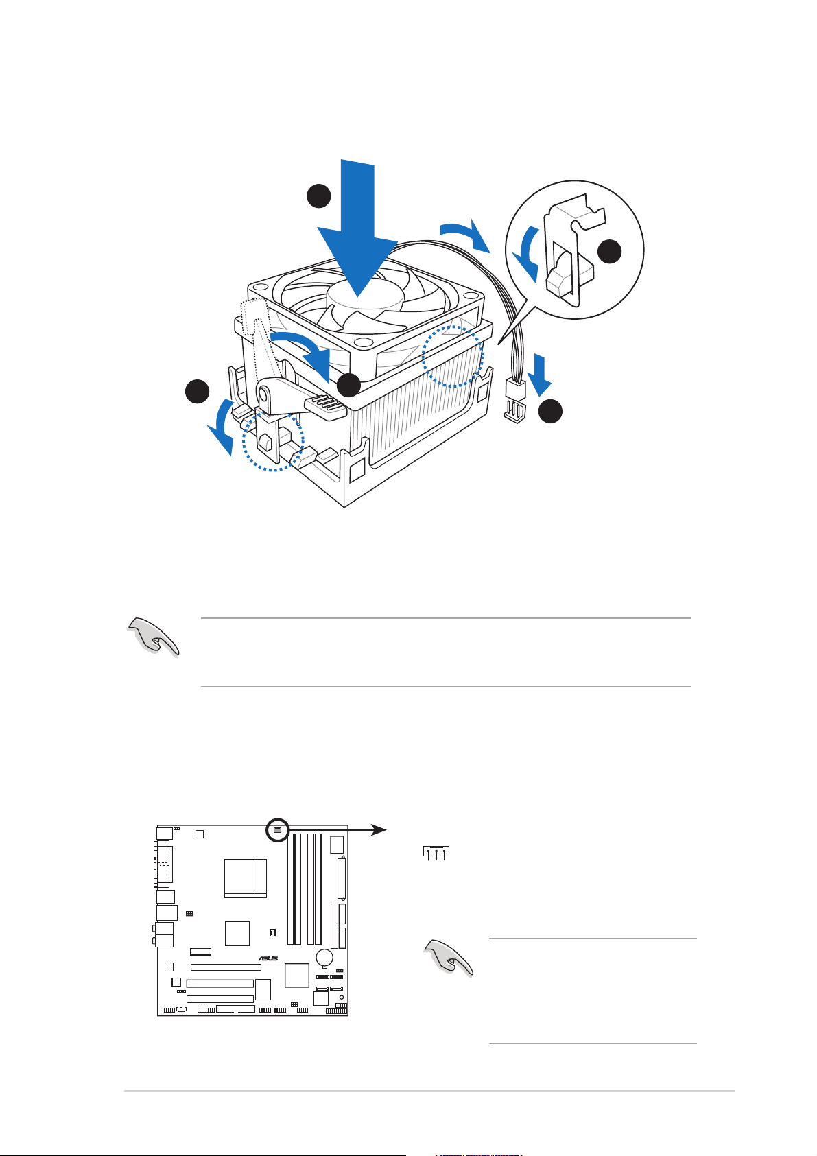
2. Attach one end of the retention bracket to the retention module
base.
1
2
3
4
5
3. Align the other end of the retention bracket (near the retention
bracket lock) to the retention module base. A clicking sound denotes
that the retention bracket is in place.
Make sure that the fan and heatsink assembly perfectly fits the
retention mechanism module base, otherwise you cannot snap the
retention bracket in place.
4. Push down the retention bracket lock on the retention mechanism to
secure the heatsink and fan to the module base.
5. When the fan and heatsink assembly is in place, connect the CPU fan
cable to the connector on the motherboard labeled CPU_FAN.
®
CPU fan connector
ASUS Vintage-AH1ASUS Vintage-AH1
ASUS Vintage-AH1
ASUS Vintage-AH1ASUS Vintage-AH1
CPU_FAN
GND
+12V
Rotation
Do not forget to connect the
CPU fan connector! Hardware
monitoring errors can occur if
you fail to plug this
connector.
2-72-7
2-7
2-72-7
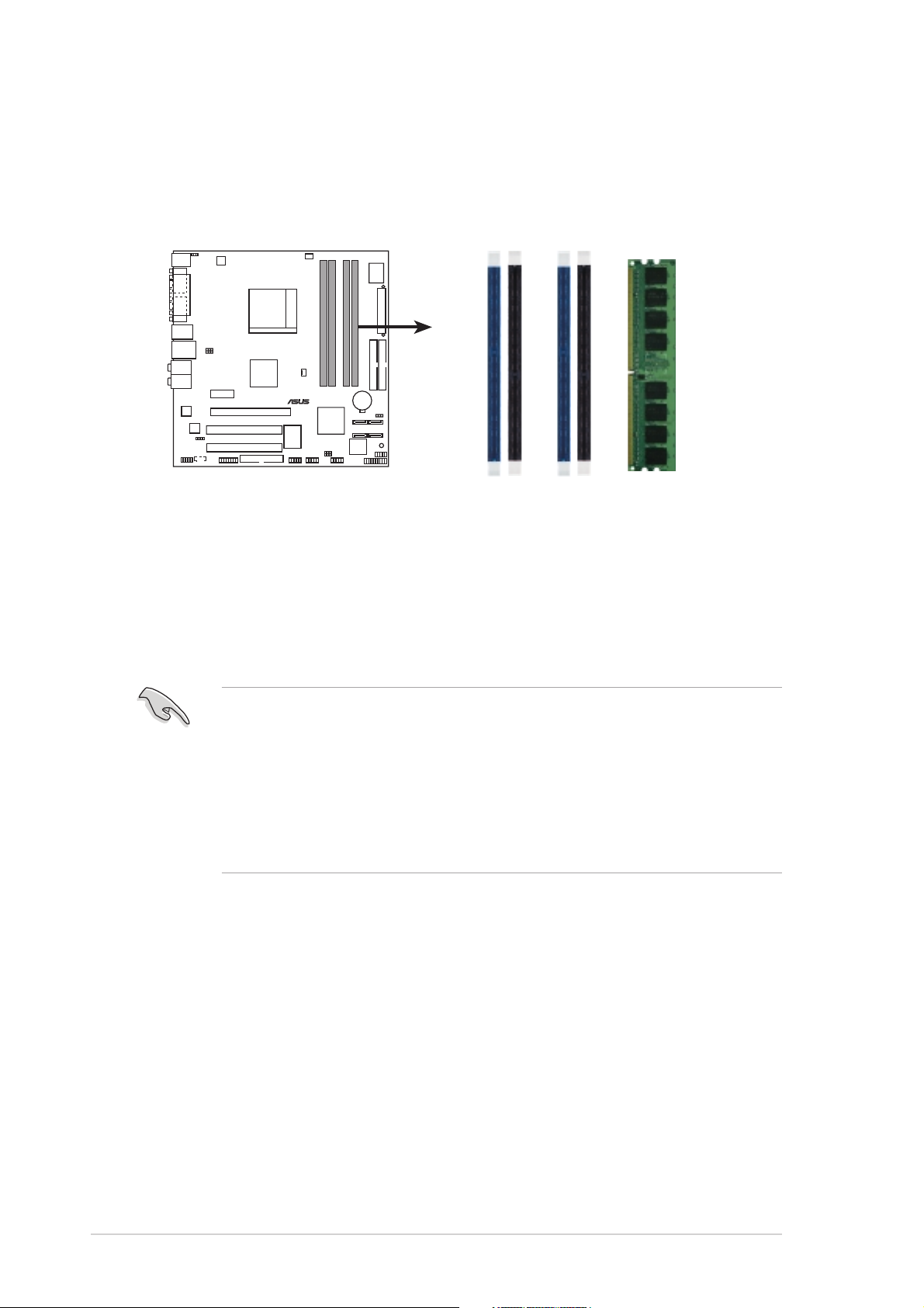
2.5 Installing a DIMM
The system motherboard comes with two Double Data Rate (DDR) Dual
Inline Memory Module (DIMM) sockets.
The following figure illustrates the location of the sockets:
DIMM_B2
®
184-pin DDR DIMM sockets
2.5.12.5.1
2.5.1
2.5.12.5.1
Memory configurationsMemory configurations
Memory configurations
Memory configurationsMemory configurations
DIMM_A1
DIMM_A2
DIMM_B1
You may install up to 4 GB system memory using 128 MB, 256 MB,
512 MB, and 1 GB DDR DIMMs.
• Install only
modules.
identical identical
identical (the same type and size) DDR memory
identical identical
• Install only ASUS-certified memory modules. Visit the ASUS website
(www.asus.com) for the latest memory Qualified Vendors List.
• Always install DIMMs with the same CAS latency. For optimum
compatibility, we recommend that you obtain memory modules from
the same vendor.
2-82-8
2-8
2-82-8
Chapter 2: Basic installationChapter 2: Basic installation
Chapter 2: Basic installation
Chapter 2: Basic installationChapter 2: Basic installation

DDR400 Qualified Vendors ListDDR400 Qualified Vendors List
DDR400 Qualified Vendors List
DDR400 Qualified Vendors ListDDR400 Qualified Vendors List
Size VendorSize Vendor
Size Vendor
Size VendorSize Vendor
256MB Kingston KVR333X64C25/256 Kingston SS D3208DH1T-6 –•••
256MB Kingston KVR333X64C25/256 Hynix DS HY5DU56822BT-D43 –•••
512MB Kingston KVR333X64C25/512 Kingston DS D3208DH1T-6 –•••
512MB Kingston KVR400X64C3A/512 Hynix DS HY5DU56822BT-D43 –•••
512MB Kingston KVR400X64C3A/512 Kingston DS D3208DH1T-5 –•••
512MB Kingston KVR400X64C3A/512 Kingston SS HY5DU12822BT-D43 –•••
256MB Kingston KVR400X64C3A/256 Hynix SS HY5DU56822BT-D43 –•••
256MB Kingston KVR400X64C3A/256 Kingston SS D3208DL3T-5A –•••
256MB Kingston KVR400X64C3A/256 PSC SS A2S56D30BTP –•••
1G Kingston KVR400X64C3A/1G Infineon DS HYB25D512800BE-5B –•••
256MB Infineon HYS64D32300GU-5-C Infineon SS HYB25D256800CE-5C 3 •••
512MB Infineon HYS64D64320GU-5-C åInfineon DS HYB25D256800CE-5C 3 •••
256MB Infineon HYS64D32300GU-5-C Infineon SS HYB25D256800CE-5C –•••
512MB Infineon HYS64D64320GU-6-C Infineon DS HYB25D256800CE-6C –•••
256MB HY HYMD232646D8J-D43 Hynix SS HY5DU56822BT-D43 –•••
512MB HY HYMD264646D8J-D43 Hynix DS HY5DU56822BT-D43 –•••
256MB HY HYMD232646B8J-J Hynix SS HY5DU56822BT-J –•••
512MB HY HYMD264646B8J-J Hynix DS HY5DU56822BT-J –•••
256MB Corsair VS256MB400 Value select SS VS32M8-5 2B0409 –•••
256MB Corsair XMS3202v3.1 Infineon SS HYB25D256807BT-5B 2 •••
512MB Corsair XMS3205v1.2 Winbond DS W942508CH-5 –•••
512MB Corsair VS512MB400 Value select DS VS32M8-5 2B0402 –•••
256MB Corsair VS256MB333 Samsung SS K4H5608380-TCB3 –•••
512MB Corsair VS512MB333 Value select SS VS32M8-6 2B0412 –•••
512MB Corsair XMS2702v3.1 Mosel DS V58C2256804SAT6 2 •••
512MB Micron MT16VDDT6464AG-335GB Micron DS MT46V32M8TG-6TG –•••
256MB Micron MT8VDDT3264AG-335GB Micron SS MT46V32M8TG-6TG 2.5 •••
256MB Micron MT8VDDT3264AG-40BGB Micron SS MT46V32M8TG-5BG 3 •••
512MB Micron MT16VDDT6464AG-40BCB Micron DS MT46V32M8TG-5BC 3 •••
256MB Samsung M368L3223FTN-CCC Samsung SS K4H560838F-TCCC 3 •••
512MB Samsung M368L6423FTN-CCC Samsung DS K4H560838F-TCCC 3 •••
256MB Samsung M368L3223FTN-CB3 Samsung SS K4H560838F-TCB3 2.5 •••
512MB Samsung M368L6423FTN-CB3 Samsung DS K4H560838F-TCB3 2.5 •••
256MB Winbond U24256ADWBG6H20 Winbond SS W942508CH-5 –•••
256MB Winbond U24256AAWBG6H20 Winbond SS W942508CH-6 –•••
512MB Winbond DDR333-512 Winbond DS W942508BH-6 –•••
512MB Winbond U24512ADWBG6H20 Winbond DS W942508CH-5 –•••
256MB Elpida U24256ADEPG6H20 Elpida SS DD2508AKTA-5C –•••
512MB Elpida U24512ADEPG6H20 Elpida DS DD2508AMTA –•••
256MB Transcend DDR400-256 Samsung SS K4H560838F-TCCC –•••
256MB Transcend DDR400-256 Mosel SS V58C2256804SAT5B –•••
512MB Transcend 102709-0001 PSC DS A2S56D3OATP 2.5 •••
512MB Transcend DDR400-512 Mosel DS V58C2256804SAT5B –•••
512MB Transcend DDR400-512 Samsung DS K4H560838F-TCCC –•••
256MB Transcend 111448-0214 PSC SS A2S56D30BTP 2.5 •••
512MB Transcend DDR333-512 Hynix DS HY5DU56822CT-J –•••
256MB Pmi 3208GATA07-04A7 Pmi SS PM4D328D50406EU –•••
512MB Pmi 3208GATA01-04A4 Pmi DS PM4D328S50403DU –•••
ModelModel
Model
ModelModel
BrandBrand
Brand
BrandBrand
Side(s)Side(s)
Side(s)
Side(s)Side(s)
ComponentComponent
Component
ComponentComponent
DIMM supportDIMM support
DIMM support
DIMM supportDIMM support
CLCL
CL
CLCL
AA
BB
A
B
AA
BB
CC
C
CC
ASUS Vintage-AH1ASUS Vintage-AH1
ASUS Vintage-AH1
ASUS Vintage-AH1ASUS Vintage-AH1
(Continued on the next page)
2-92-9
2-9
2-92-9
Size VendorSize Vendor
Size Vendor
Size VendorSize Vendor
256MB Kingmax MPMB62D-38LT3R Mosel SS V58C2256804SAT6 –•••
512MB Kingmax MPMC22D-38HT3R Hynix DS HY5DU56822BT-J –•••
256MB Kingmax MPXB62D-38KT3R Kingmax SS KDL388P4LA-50 –•••
512MB Kingmax MPXC22D-38KT3R Kingmax DS KDL388P4EA-50 –•••
256MB Mosel V826632K24SATG-D3 Mosel SS V58C2256804SAT5 3 •••
512MB Mosel V826664K24SATG-D3 Mosel DS V58C2256804SAT5 3 •••
256MB Nanya NT256D64S88B1G-5T Nanya SS NT5DS32M8BT-5T 3 •••
512MB Apacer 77.90728.U1G Apacer DS AM3A568AJT-6B 2.5 •••
256MB Apacer 77.10636.46G Samsung SS K4H560838E-TCCC 3 ––•
256MB Apacer 77.10636.56G Mosel SS V58C2256804SAT5B 3 •••
512MB Apacer 77.10736.11G Infineon DS HYB25D256800BT-5B 3 •••
256MB Smart U24256ADSRG6H20 Smart SS D32M8XS50H3X4AMV –•••
256MB Smart U24256ADSRG6H20 Smart SS D32M8XS60HBX4AMV –•••
512MB Smart U24512ADSRG6H20 Smart DS D32M8XS50H3X4AMV –•••
512MB Smart U24512ADSRG6H20 Smart DS D32M8XS60HBX4AMV –•••
256MB Twinmos DDR333-256 Twinmos SS TMD7608F8E60B 2.5 •••
256MB Twinmos M2G9108A-TT Twinmos SS TMD7608F8E501 2.5 •••
256MB Promos V826632K24SCTG-D0 Promos SS V58C2256804SCT5B 2.5 •••
512MB Promos V826664K24SCTG-D0 Promos DS V58C2256804SCT5B 2.5 •••
512MB BiaoXing BXXC22D-38KT3B BiaoXing DS VM256D328BT-5 –•••
256MB Vdata MDYVD6F4G2880B1E0H Vdata SS VDD9616A8A-5C –•••
ModelModel
Model
ModelModel
BrandBrand
Brand
BrandBrand
Side(s)Side(s)
Side(s)
Side(s)Side(s)
ComponentComponent
Component
ComponentComponent
DIMM supportDIMM support
DIMM support
DIMM supportDIMM support
CLCL
CL
CLCL
AA
BB
A
B
AA
BB
CC
C
CC
Side(s): SS - Side(s): SS -
Side(s): SS - Single-Sided
Side(s): SS - Side(s): SS DIMM Support:DIMM Support:
DIMM Support:
DIMM Support:DIMM Support:
AA
A - supports one module inserted into either the blue slots, in a Single-channel
AA
DS -DS -
D S - Double-Sided
DS -DS -
memory configuration.
BB
B - supports on pair of modules inserted into either the blue slots or the black slots
BB
as one pair of Dual-channel memory configuration.
CC
C - support for 4 modules inserted into the blue and black slots as two pairs of
CC
Dual-channel memory configuration.
Visit the ASUS website (www.asus.com) for the latest DDR 400 Qualified
Vendors List.
2-102-10
2-10
2-102-10
Chapter 2: Basic installationChapter 2: Basic installation
Chapter 2: Basic installation
Chapter 2: Basic installationChapter 2: Basic installation
2.5.22.5.2
2.5.2
2.5.22.5.2
Installing a DIMMInstalling a DIMM
Installing a DIMM
Installing a DIMMInstalling a DIMM
Make sure to unplug the power supply before adding or removing DIMMs
or other system components. Failure to do so may cause severe damage
to both the motherboard and the components.
1. Unlock a DIMM socket by
pressing the retaining clips
outward.
2. Align a DIMM on the socket such
that the notch on the DIMM
matches the break on the
socket.
1
Unlocked retaining clipUnlocked retaining clip
Unlocked retaining clip
Unlocked retaining clipUnlocked retaining clip
A DDR DIMM is keyed with a notch so that it fits in only one direction.
DO NOT force a DIMM into a socket to avoid damaging the DIMM.
2
DDR DIMM notchDDR DIMM notch
DDR DIMM notch
DDR DIMM notchDDR DIMM notch
1
3. Firmly insert the DIMM into the
socket until the retaining clips
snap back in place and the DIMM
is properly seated.
Locked Retaining ClipLocked Retaining Clip
Locked Retaining Clip
Locked Retaining ClipLocked Retaining Clip
2.5.32.5.3
2.5.3
2.5.32.5.3
Removing a DIMMRemoving a DIMM
Removing a DIMM
Removing a DIMMRemoving a DIMM
Follow these steps to remove a DIMM.
1. Simultaneously press the
retaining clips outward to
unlock the DIMM.
1
3
2
DDR DIMM notchDDR DIMM notch
DDR DIMM notch
DDR DIMM notchDDR DIMM notch
1
Support the DIMM lightly with your fingers when pressing the retaining
clips. The DIMM might get damaged when it flips out with extra force.
2. Remove the DIMM from the socket.
2-102-10
2-10
2-102-10
Chapter 2: Basic installationChapter 2: Basic installation
Chapter 2: Basic installation
Chapter 2: Basic installationChapter 2: Basic installation

2.6 Expansion slots
In the future, you may need to install expansion cards. The following
sub-sections describe the slots and the expansion cards that they support.
Make sure to unplug the power cord before adding or removing
expansion cards. Failure to do so may cause you physical injury and
damage motherboard components.
2.6.12.6.1
2.6.1
2.6.12.6.1
To install an expansion card:
1. Before installing the expansion card, read the documentation that
came with it and make the necessary hardware settings for the card.
2. Remove the system unit cover (if your motherboard is already
installed in a chassis).
3. Remove the bracket opposite the slot that you intend to use. Keep
the screw for later use.
4. Align the card connector with the slot and press firmly until the card is
completely seated on the slot.
5. Secure the card to the chassis with the screw you removed earlier.
6. Replace the system cover.
2.6.22.6.2
2.6.2
2.6.22.6.2
After installing the expansion card, configure it by adjusting the software
settings.
Installing an expansion cardInstalling an expansion card
Installing an expansion card
Installing an expansion cardInstalling an expansion card
Configuring an expansion cardConfiguring an expansion card
Configuring an expansion card
Configuring an expansion cardConfiguring an expansion card
1. Turn on the system and change the necessary BIOS settings, if any.
See Chapter 5 for information on BIOS setup.
2. Assign an IRQ to the card. Refer to the tables on the next page.
3. Install the software drivers for the expansion card.
ASUS Vintage-AH1ASUS Vintage-AH1
ASUS Vintage-AH1
ASUS Vintage-AH1ASUS Vintage-AH1
2-112-11
2-11
2-112-11
 Loading...