

Page 1
V-Series P5P43
R
R
ASUS PC (Desktop Barebone)
Installation Manual
Page 2

E4213
First Edition V1
January 2009
Copyright © 2009 ASUSTeK Computer INC. All Rights Reserved.
No part of this manual, including the products and software described in it, may be reproduced,
transmitted, transcribed, stored in a retrieval system, or translated into any language in any form or by any
means, except documentation kept by the purchaser for backup purposes, without the express written
permission of ASUSTeK Computer INC. (“ASUS”).
Product warranty or service will not be extended if: (1) the product is repaired, modied or altered, unless
such repair, modication of alteration is authorized in writing by ASUS; or (2) the serial number of the
product is defaced or missing.
ASUS PROVIDES THIS MANUAL “AS IS” WITHOUT WARRANTY OF ANY KIND, EITHER EXPRESS
OR IMPLIED, INCLUDING BUT NOT LIMITED TO THE IMPLIED WARRANTIES OR CONDITIONS OF
MERCHANTABILITY OR FITNESS FOR A PARTICULAR PURPOSE. IN NO EVENT SHALL ASUS, ITS
DIRECTORS, OFFICERS, EMPLOYEES OR AGENTS BE LIABLE FOR ANY INDIRECT, SPECIAL,
INCIDENTAL, OR CONSEQUENTIAL DAMAGES (INCLUDING DAMAGES FOR LOSS OF PROFITS,
LOSS OF BUSINESS, LOSS OF USE OR DATA, INTERRUPTION OF BUSINESS AND THE LIKE),
EVEN IF ASUS HAS BEEN ADVISED OF THE POSSIBILITY OF SUCH DAMAGES ARISING FROM ANY
DEFECT OR ERROR IN THIS MANUAL OR PRODUCT.
SPECIFICATIONS AND INFORMATION CONTAINED IN THIS MANUAL ARE FURNISHED FOR
INFORMATIONAL USE ONLY, AND ARE SUBJECT TO CHANGE AT ANY TIME WITHOUT NOTICE,
AND SHOULD NOT BE CONSTRUED AS A COMMITMENT BY ASUS. ASUS ASSUMES NO
RESPONSIBILITY OR LIABILITY FOR ANY ERRORS OR INACCURACIES THAT MAY APPEAR IN THIS
MANUAL, INCLUDING THE PRODUCTS AND SOFTWARE DESCRIBED IN IT.
Products and corporate names appearing in this manual may or may not be registered trademarks or
copyrights of their respective companies, and are used only for identication or explanation and to the
owners’ benet, without intent to infringe.
ii
Page 3

Table of contents
Notices ......................................................................................................... vi
Safety information
About this guide
System package contents
Chapter 1 System introduction
1.1 Welcome! ...................................................................................... 1-2
1.2 Front panel
1.3 Rear panel
Voltage selector .............................................................................. 1-7
1.4 Internal components
Chapter 2 Basic installation
2.1 Preparation ................................................................................... 2-2
2.2 Before you proceed
2.3 Removing the side cover and front panel assembly
2.4 Central Processing Unit (CPU)
2.4.1 Overview .........................................................................
2.4.2 Installing CPU .................................................................
2.4.3 Installing the CPU fan and heatsink assembly ................
2.5 Installing a DIMM
2.5.1 Memory congurations ....................................................
2.5.2 Installing a DDR2 DIMM ...............................................
2.5.3 Removing a DDR2 DIMM .............................................
2.6 Expansion slots
2.6.1 Installing an expansion card .........................................
2.6.2 Conguring an expansion card .....................................
2.6.3 PCI slots ........................................................................
2.6.4 PCI Express x1 slot .......................................................
2.6.5 PCI Express x16 slot .....................................................
2.7 Installing an optical drive
2.8 Installing a hard disk drive
2.9 Installing the card reader
2.10 Installingaoppydiskdrive
2.11 Re-connecting cables
2.12 Reinstalling the cover
..................................................................................... vii
....................................................................................... viii
........................................................................... x
................................................................................... 1-2
..................................................................................... 1-4
.................................................................... 1-8
..................................................................... 2-2
................ 2-3
................................................... 2-4
.......................................................................... 2-8
.......................................................................... 2-17
.......................................................... 2-21
........................................................ 2-22
.......................................................... 2-24
..................................................... 2-26
................................................................ 2-27
................................................................ 2-28
2-4
2-4
2-6
2-9
2-16
2-16
2-17
2-17
2-20
2-20
2-20
iii
Page 4

Table of contents
Chapter 3 Starting up
3.1 Installing an operating system ................................................... 3-2
3.2 Powering up
3.3 Support DVD information
3.3.1 Running the support DVD ...............................................
3.3.2 Utilities menu ..................................................................
3.3.3 Manual menu ..................................................................
3.3.4 Make Disk menu .............................................................
3.3.5 ASUS Contact information ..............................................
3.3.6 Other information ..........................................................
3.4 Software information
ASUS PC Probe II ........................................................................ 3-12
Chapter 4 Motherboard introduction
4.1 Introduction .................................................................................. 4-2
4.2 Motherboard layout
4.3 Jumpers
4.3 Connectors
Chapter 5 BIOS setup
5.1 Managing and updating your BIOS ............................................ 5-2
5.1.1 ASUS Update utility ........................................................
5.1.2 Creating a bootable oppy disk .......................................
5.1.3 ASUS EZ Flash 2 utility ...................................................
5.1.4 AFUDOS utility ................................................................
5.1.5 ASUS CrashFree BIOS 3 utility ......................................
5.2 BIOS setup program
5.2.1 BIOS menu screen .........................................................
5.2.2 Menu bar ........................................................................
5.2.3 Navigation keys ..............................................................
5.2.4 Menu items ...................................................................
5.2.5 Sub-menu items ............................................................
5.2.6 Conguration elds .......................................................
5.2.7 Pop-up window .............................................................
5.2.8 Scroll bar .......................................................................
5.2.9 General help .................................................................
.................................................................................. 3-2
............................................................ 3-2
................................................................. 3-12
...................................................................... 4-2
........................................................................................ 4-3
................................................................................... 4-4
.................................................................. 5-10
3-3
3-4
3-7
3-8
3-9
3-10
5-2
5-5
5-6
5-7
5-9
5-11
5-11
5-11
5-12
5-12
5-12
5-12
5-12
5-12
iv
Page 5

Table of contents
5.3 Main menu .................................................................................. 5-13
5.3.1 System Time .................................................................
5.3.2 System Date .................................................................
5.3.3 Legacy Diskette A .........................................................
5.3.4 SATA 1~6 ......................................................................
5.3.5 Storage Conguration ...................................................
5.3.6 System Information .......................................................
5.4 Advanced menu
5.4.1 Jumperfree Conguration .............................................
5.4.2 CPU Conguration ........................................................
5.4.3 Chipset ..........................................................................
5.4.4 Onboard Devices Conguration ....................................
5.4.5 USB Conguration ........................................................
5.4.6 PCI PnP ........................................................................
5.5 Power menu
5.5.1 Suspend Mode ..............................................................
5.5.2 ACPI 2.0 Support ..........................................................
5.5.3 ACPI APIC Support .......................................................
5.5.4 APM Conguration ........................................................
5.5.5 Hardware Monitor .........................................................
5.6 Boot menu
5.6.1 Boot Device Priority ......................................................
5.6.2 Boot Settings Conguration ..........................................
5.6.3 Security .........................................................................
5.7 Tools menu
5.7.1 ASUS EZ Flash 2 ..........................................................
5.7.2 Express Gate ................................................................
5.7.3 AI NET 2
5.8 Exit menu
......................................................................... 5-17
................................................................................ 5-27
.................................................................................. 5-30
................................................................................. 5-34
........................................................................ 5-36
.................................................................................... 5-37
5-13
5-13
5-13
5-14
5-15
5-16
5-17
5-20
5-22
5-23
5-25
5-26
5-27
5-27
5-27
5-28
5-29
5-30
5-31
5-32
5-34
5-35
v
Page 6

Notices
Federal Communications Commission Statement
This device complies with Part 15 of the FCC Rules. Operation is subject to the
following two conditions:
•
This device may not cause harmful interference, and
•
This device must accept any interference received including interference that
may cause undesired operation.
This equipment has been tested and found to comply with the limits for a
Class B digital device, pursuant to Part 15 of the FCC Rules. These limits are
designed to provide reasonable protection against harmful interference in a
residential installation. This equipment generates, uses and can radiate radio
frequency energy and, if not installed and used in accordance with manufacturer’s
instructions, may cause harmful interference to radio communications. However,
there is no guarantee that interference will not occur in a particular installation. If
this equipment does cause harmful interference to radio or television reception,
which can be determined by turning the equipment off and on, the user is
encouraged to try to correct the interference by one or more of the following
measures:
•
Reorient or relocate the receiving antenna.
•
Increase the separation between the equipment and receiver.
•
Connect the equipment to an outlet on a circuit different from that to which the
receiver is connected.
•
Consult the dealer or an experienced radio/TV technician for help.
WARNING! The use of shielded cables for connection of the monitor to the
graphics card is required to assure compliance with FCC regulations. Changes
or modications to this unit not expressly approved by the party responsible for
compliance could void the user’s authority to operate this equipment.
Canadian Department of Communications Statement
This digital apparatus does not exceed the Class B limits for radio noise emissions
from digital apparatus set out in the Radio Interference Regulations of the
Canadian Department of Communications.
This class B digital apparatus complies with Canadian ICES-003.
vi
Page 7

Safety information
Electrical safety
•
To prevent electrical shock hazard, disconnect the power cable from the
electrical outlet before relocating the system.
•
When adding or removing devices to or from the system, ensure that the power
cables for the devices are unplugged before the signal cables are connected.
•
If the power supply is broken, do not try to x it by yourself. Contact a qualied
service technician or your retailer.
Operation safety
•
Before installing devices into the system, carefully read all the documentation
that came with the package.
•
Before using the product, make sure all cables are correctly connected and the
power cables are not damaged. If you detect any damage, contact your dealer
immediately.
•
To avoid short circuits, keep paper clips, screws, and staples away from
connectors, slots, sockets and circuitry.
•
Avoid dust, humidity, and temperature extremes. Do not place the product in
any area where it may become wet. Place the product on a stable surface.
•
If you encounter technical problems with the product, contact a qualied
service technician or your retailer.
Lithium-Ion Battery Warning
CAUTION: Danger of explosion if battery is incorrectly replaced. Replace
only with the same or equivalent type recommended by the manufacturer.
Dispose of used batteries according to the manufacturer’s instructions.
VORSICHT: Explosionsgetahr bei unsachgemäßen Austausch der Batterie.
Ersatz nur durch denselben oder einem vom Hersteller empfohlenem
ähnljchen Typ. Entsorgung gebrauchter Batterien nach Angaben des
Herstellers.
LASER PRODUCT WARNING
CLASS 1 LASER PRODUCT
vii
Page 8

About this guide
Audience
This guide provides general information and installation instructions about
the ASUS Vintage V-Series P5P43 barebone system. This guide is intended
for experienced users and integrators with hardware knowledge of personal
computers.
How this guide is organized
This guide contains the following parts:
1. Chapter 1: System introduction
This chapter gives a general description of the ASUS
V-Series P5P43. The chapter lists the system features, including introduction
on the front and rear panel, and internal components.
2. Chapter 2: Basic installation
This chapter provides step-by-step instructions on how to install components
in the system.
3. Chapter 3: Starting up
This chapter helps you power up the system and install drivers and utilities
from the support DVD.
4. Chapter 4: Motherboard introduction
This chapter gives information about the motherboard that comes with the
system. This chapter includes the motherboard layout, jumper settings, and
connector locations.
5. Chapter 5: BIOS setup
This chapter tells you how to change system settings through the BIOS Setup
menus and describes the BIOS parameters.
viii
Page 9

Conventions used in this guide
WARNING: Information to prevent injury to yourself when trying to
complete a task.
CAUTION: Information to prevent damage to the components when
trying to complete a task.
IMPORTANT: Instructions that you MUST follow to complete a task.
NOTE: Tips and additional information to aid in completing a task.
Wheretondmoreinformation
Refer to the following sources for additional information and for product and
software updates.
1. ASUS Websites
The ASUS websites worldwide provide updated information on ASUS
hardware and software products. Refer to the ASUS contact information.
2. Optional Documentation
Your product package may include optional documentation, such as warranty
yers, that may have been added by your dealer. These documents are not
part of the standard package.
ix
Page 10

System package contents
Check your V-Series P5P43 system package for the following items.
If any of the items is damaged or missing, contact your retailer immediately.
Item description
1. ASUS V-Series P5P43 barebone system with
• ASUS motherboatd
• Power supply unit
• ASUS chassis
2. Cable
• AC power cable
3. Support DVD
4. User guide
5. Telecom Adapter Card (Optional)
x
Page 11

R
R
Chapter 1
This chapter gives you a general
description of the ASUS
V-Series P5P43. The chapter lists the
system features including introduction
on the front and rear panel, and
internal components.
System introduction
Page 12
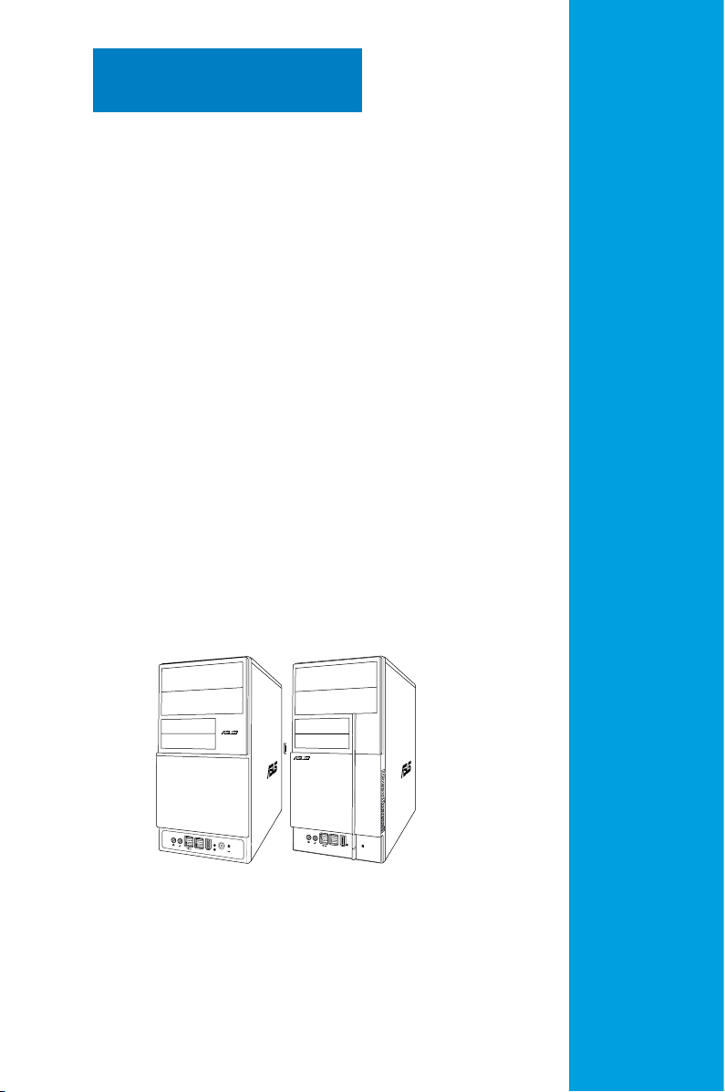
1.1 Welcome!
R
Thank you for buying the ASUS V-Series P5P43!
The ASUS V-Series P5P43 is an all-in-one barebone system with a versatile home
entertainment feature.
The system comes in a stylish casing and powered by the ASUS motherboard that
supports the Intel® Core™2 Quad / Core™2 Extreme / Core™2 Duo / Pentium
®
D /
Pentium® 4 and Celeron® E1000 Series and Celeron 400 Series processors in the
775-land package.
The system supports up to 8 GB of system memory using DDR2-1066/800/667
DIMMs. High-resolution graphics via integrated graphics controller or PCI Express
x16 slot, Serial ATA, USB 2.0, and 8-channel audio feature the system and take
you ahead in the world of power computing.
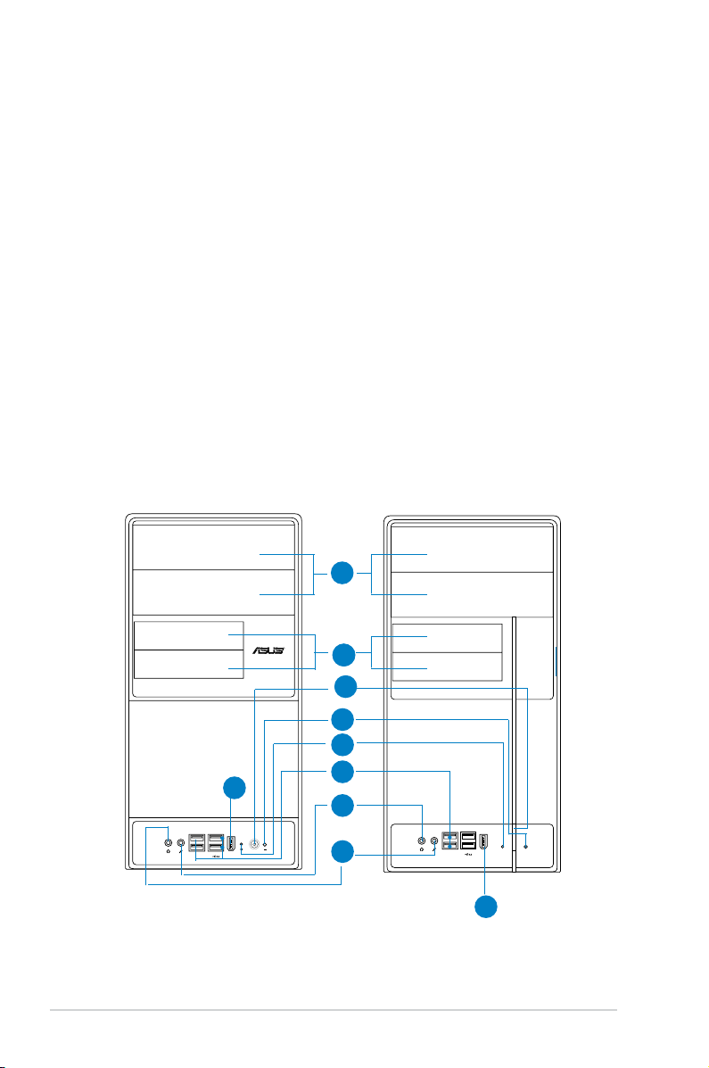
1.2 Front panel
The front panel includes the optical drive bays, oppy disk drive slot, power button,
and several I/O ports are located at the front panel.
1
2
2
3
4
5
9
1-2 Chapter 1: System introduction
6
7
8
9
Page 13

1. Two empty 5.25-inch bays. These bays are for IDE optical drives.
2. 3.5-inch drive bays
3. Power button.
4. Reset button.
. These slots are for 3.5-inch oppy or hard disk drives.
Press this button to turn the system on.
Press this button to reboot the system without turning off the
power.
5. HDD LED. This LED lights up when data is read from or written to the hard
disk drive.
6. USB 2.0 ports. These Universal Serial Bus 2.0 (USB 2.0) ports are available
for connecting USB 2.0 devices such as a mouse, printer, scanner, camera,
PDA, and others.
7. Headphone port. This Line Out (green) port connects a headphone with a
stereo mini-plug.
8. Microphone port.
This Mic (pink) port connects a microphone.
9. IEEE1394 port.
This V-series provide V2/V3 two types of front panel for users to choose, please
refer to your product package for the front panel type you purchased.
1-3ASUS V-Series P5P43
Page 14
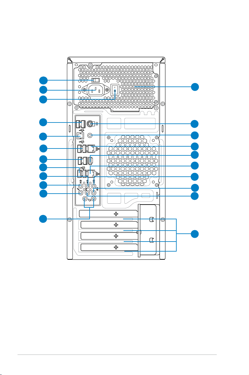
1.3 Rear panel
1394
eSATA
SPDIF OUT
1
2
3
4
5
6
7
8
9
10
11
12
13
14
15
16
17
18
19
20
21
22
The system rear panel includes the power connector and several I/O ports that
allow convenient connection of devices.
1. Voltage selector.
2. Power connector.
3. Power Switch.
4. USB 2.0 ports.
This switch allows you to adjust the system input voltage
according to the voltage supply in your area. See the section “Voltage
selector” on page 1-6 before adjusting this switch.
This connector is for the power cable and plug.
This switch is for switching on/off the power supply unit.
These two 4-pin Universal Serial Bus (USB) ports are
available for connecting USB 2.0 devices.
1-4 Chapter 1: System introduction
Page 15
5. Optical S/PDIF Out port. This port connects an external audio output device
via an optical S/PDIF cable.
6. USB 2.0 ports.
These two 4-pin Universal Serial Bus (USB) ports are
available for connecting USB 2.0 devices.
7. External SATA ports. This port connects to an external Serial ATA hard disk
drive.
DO NOT insert different connectors to the external SATA port.
8. USB 2.0 ports. These two 4-pin Universal Serial Bus (USB) ports are
available for connecting USB 2.0 devices.
9. Rear Speaker Out port (black).
This port connects the rear speakers in a
4-channel, 6-channel, or 8-channel audio conguration..
10. Center / Subwoofer port (orange).
subwoofer speakers.11
. Line In port (light blue)
This port connects the center /
. This port connects the
tape, CD, DVD player, or other audio sources.
12. Line Out port (green)
. This port connects a headphone or a speaker. In
4-channel, 6-channel, and 8-channel conguration, the function of this port
becomes Front Speaker Out.
13 Microphone port (pink).
14. Side Speaker Out port (gray)
This port connects a microphone.
. This port connects the side speakers in an
8-channel audio conguration.
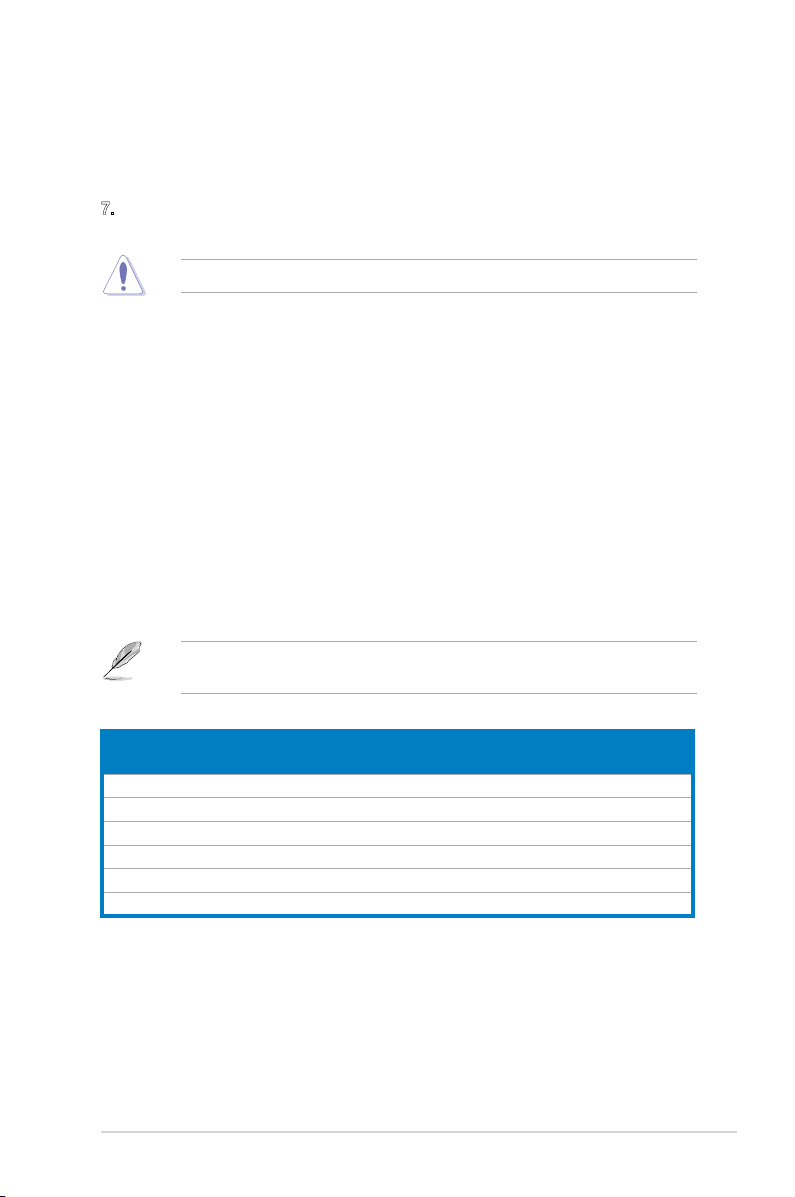
Refer to the audio conguration table below for the function of the audio ports in
2, 4, 6, or 8-channel conguration.
Audio2,4,6,or8-channelconguration
Port
Light Blue Line In Line In Line In Line In
Green Line Out Front Speaker Out Front Speaker Out Front Speaker Out
Pink Mic In Mic In Mic In Mic In
Orange – – Center/Subwoofer Center/Subwoofer
Black – Rear Speaker Out Rear Speaker Ou Rear Speaker Out
Gray – – – Side Speaker Out
Headset
2-channel
4-channel 6-channel 8-channel
1-5ASUS V-Series P5P43
Page 16

15. Antenna jack. This jack is on the onboard wireless LAN module that allows
you to set up a wireless network and exchange information with other
wireless devices without tangling cables and wires. Connect the moveable
omni-directional antenna to this jack.
16. LAN (RJ-45) port.
This port allows Gigabit connection to a Local Area
Network (LAN) through a network hub.
17. IEEE 1394a port.
This 6-pin IEEE 1394a port provides high-speed
connectivity for audio/video devices, storage peripherals, PCs, or portable
devices.
18. LAN (RJ-45) port.
This port allows Gigabit connection to a Local Area
Network (LAN) through a network hub.
19. Coaxial S/PDIF Out port.
This port connects an external audio output device
via a coaxial S/PDIF cable.
20. PS/2 keyboard port. This purple 6-pin connector is for a PS/2 keyboard.
21. Power supply unit fan vent.
This vent is for the PSU fan that provides
ventilation inside the power supply unit.
22. Expansion slot covers.
Remove these covers when installing expansion
cards.
1-6 Chapter 1: System introduction
Page 17
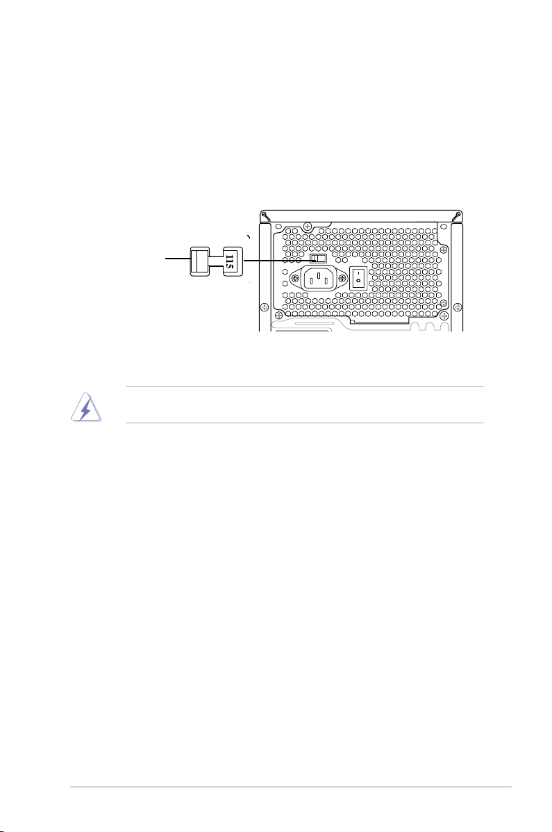
Voltage selector
The PSU has a 115 V/230 V voltage selector switch located beside the power
connector. Use this switch to select the appropriate system input voltage according
to the voltage supply in your area.
If the voltage supply in your area is 100-127 V, set this switch to 115 V.
If the voltage supply in your area is 200-240 V, set this switch to 230 V.
115V/230V
Voltage selector
Setting the switch to 115V in a 230V environment or 230V in a 115V
environment will seriously damage the system!
1-7ASUS V-Series P5P43
Page 18
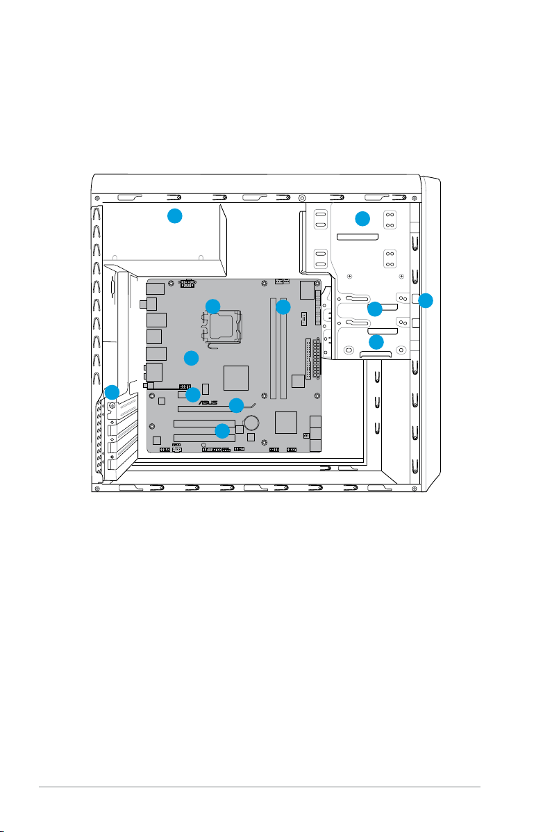
1.4 Internal components
2
1
3
5
4
P5QL-M DELUXE/WIFI-AP
9
6
7
12
8
10
11
The illustration below is the internal view of the system when you remove the top
cover and the power supply unit. The installed components are labeled for your
reference. Proceed to Chapter 2 for instructions on installing additional system
components.
1. Front panel cover
2. 5.25-inch optical drive bays
3. Floppy disk drive bay
4. Hard disk drive bay
5. Power supply unit
6. CPU socket
7. DIMM sockets
1-8 Chapter 1: System introduction
8. ASUS motherboard
9. PCI Express x16 slot
10. PCI Express x1 slot
11. PCI slot
12. Metal bracket lock
Page 19
Chapter 2
R
R
This chapter provides step-by-step
instructions on how to install
components in the system.
Basic installation
Page 20
2.1 Preparation
SB_PWR
ON
Standy Power Powered Off
OFF
P5QL-M DELUXE/WIFI-AP
P5QL-M DELUXE/WIFI-AP Onboard LED
Before you proceed, make sure that you have all the components you plan to
install in the system.
Basic components to install
1. Central Processing Unit (CPU)
2. DDR2 Dual Inline Memory Module (DIMM)
3. Expansion card(s)
4. Hard disk drive
5. Optical drive
6. Floppy disk drive
Tool
Phillips (cross) screw driver
2.2 Before you proceed
Take note of the following precautions before you install components into the
system.
•
Use a grounded wrist strap or touch a safely grounded object or a metal
object, such as the power supply case, before handling components to
avoid damaging them due to static electricity.
•
Hold components by the edges to avoid touching the ICs on them.
•
Whenever you uninstall any component, place it on a grounded antistatic
pad or in the bag that came with the component.
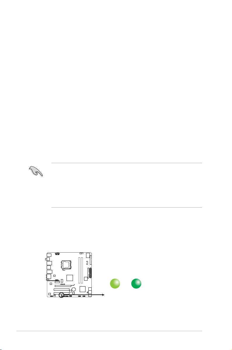
The motherboard comes with an onboard standby power LED. This LED lights
up to indicate that the system is ON, in sleep mode or in soft-off mode, and not
powered OFF. Unplug the power cable from the power outlet and make sure that
the standby power LED is OFF before installing any system component.
2-2 Chapter 2: Basic installation
Page 21
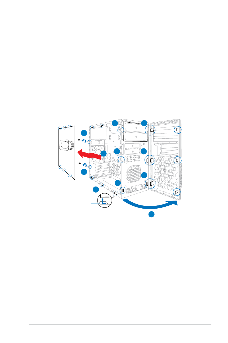
2.3 Removing the side cover and front
panel assembly
1. Remove the cover screws on the rear panel.
2. Pull the side cover toward the rear panel until its hooks disengage from the
chassis tab holes. Set the side cover aside.
3. Locate the front panel assembly hooks, then lift them until they disengage
from the chassis.
4. Swing the front panel assembly to the right, until the hinge-like tabs on the
right side of the assembly are exposed.
5. Remove the front panel assembly, then set aside.
3 4
1
Air duct
3
2
4
Chassis tab holes
1
3
2
4
4
2-3ASUS V-Series P5P43
Page 22
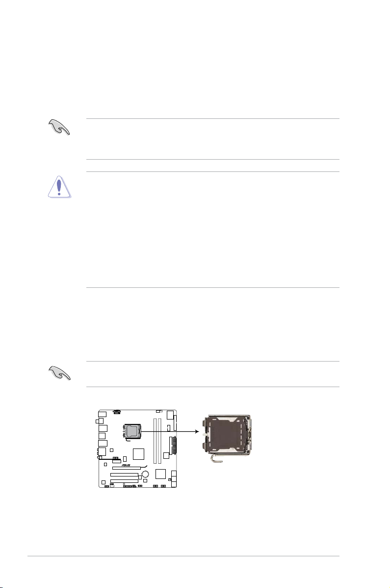
2.4 Central Processing Unit (CPU)
P5QL-M DELUXE/WIFI-AP
P5QL-M DELUXE/WIFI-AP CPU socket 775
2.4.1 Overview
The motherboard comes with a surface mount LGA775 socket designed for the
Intel® Core™2 Quad / Core™2 Extreme / Core™2 Duo / Pentium
®
D / Pentium® 4
and Celeron® E1000 Series and Celeron 400 Series processors.
• Make sure that all power cables are unplugged before installing the CPU.
• Connect the chassis fan cable to the CHA_FAN connector to ensure
system stability.
•
Upon purchase of the motherboard, make sure that the PnP cap is on
the socket and the socket contacts are not bent. Contact your retailer
immediately if the PnP cap is missing, or if you see any damage to the PnP
cap/socket contacts/motherboard components. ASUS will shoulder the cost
of repair only if the damage is shipment/transit-related.
•
Keep the cap after installing the motherboard. ASUS will process Return
Merchandise Authorization (RMA) requests only if the motherboard comes
with the cap on the LGA775 socket.
• The product warranty does not cover damage to the socket contacts
resulting from incorrect CPU installation/removal, or misplacement/loss/
incorrect removal of the PnP cap.
2.4.2 Installing CPU
To install a CPU:
1. Locate the CPU socket on the motherboard.
Before installing the CPU, make sure that the socket box is facing towards you
and the load lever is on your left.
2-4 Chapter 2: Basic installation
Page 23
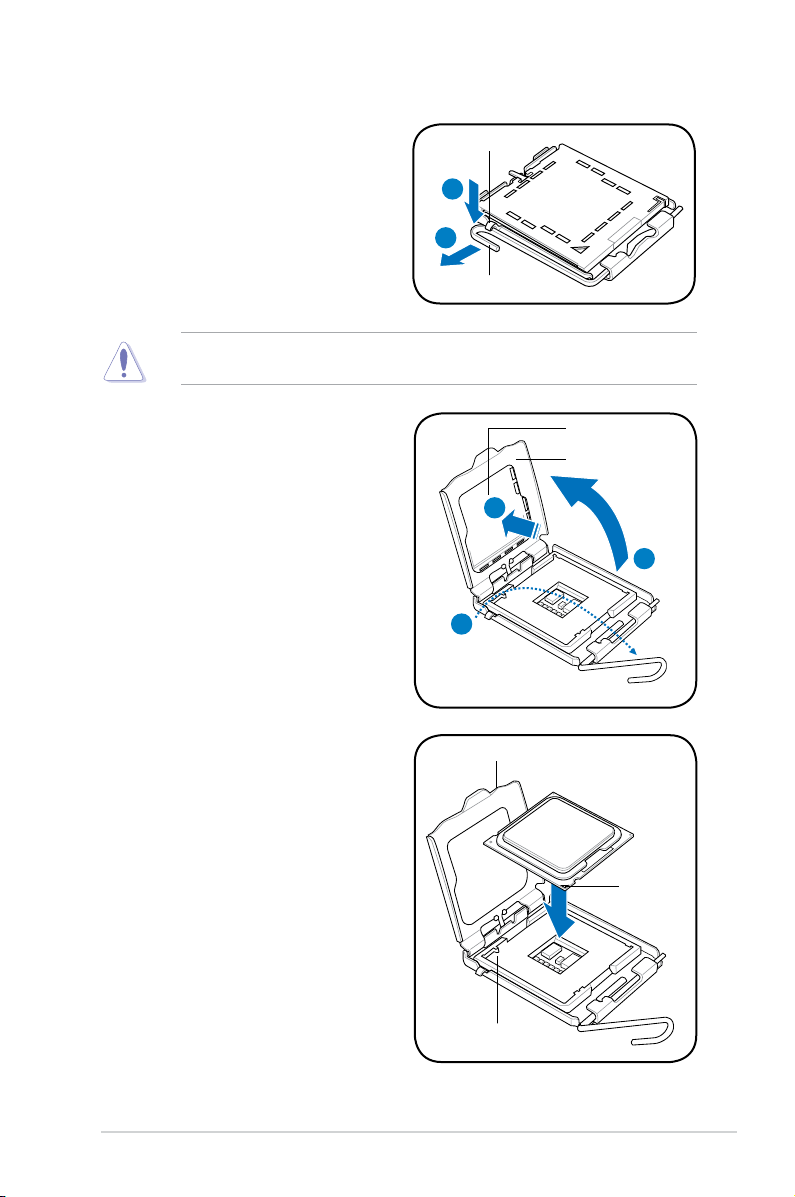
2. Press the load lever with your thumb
(A), then move it to the left (B) until it
is released from the retention tab.
To prevent damage to the socket pins, do not remove the PnP cap unless you
are installing a CPU.
Retention tab
A
B
Load lever
3. Lift the load lever in the direction of
the arrow to a 135º angle.
4. Lift the load plate with your thumb
and forenger to a 100º angle (4A),
then push the PnP cap from the
load plate window to remove (4B).
5. Position the CPU over the socket,
making sure that the gold triangle
is on the bottom-left corner of the
socket then t the socket alignment
key into the CPU notch.
PnP cap
Load plate
4B
4A
3
CPU notch
Gold
triangle
mark
Alignment key
2-5ASUS V-Series P5P43
Page 24
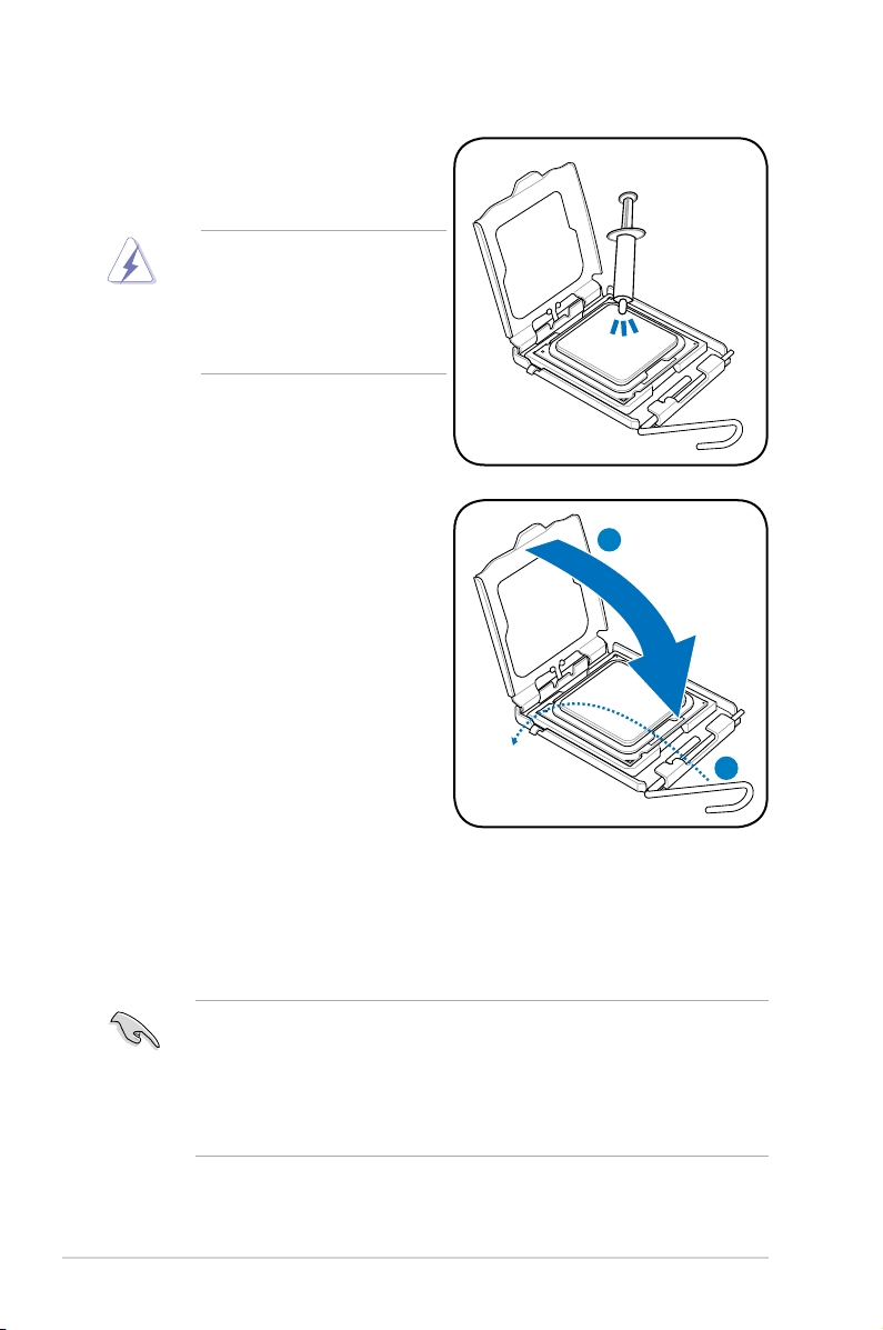
6. Apply Thermal Interface Material
on the CPU before closing the load
plate.
DO NOT eat the Thermal
Interface Material. If it gets
into your eyes or touches
your skin, make sure to wash
it off immediately, and seek
professional medical help.
7. Close the load plate (A), then push
the load lever (B) until it snaps into
the retention tab.
A
B
2.4.3 Installing the CPU fan and heatsink assembly
The Intel® Pentium® 4 LGA775 processor requires a specially designed heatsink
and fan assembly to ensure optimum thermal condition and performance.
• When you buy a boxed Intel® Pentium® 4 processor, the package
includes the CPU fan and heatsink assembly. If you buy a CPU separately,
make sure that you use only Intel®-certied multi-directional heatsink and
fan.
®
• Your Intel
push-pin design and requires no tool to install.
2-6 Chapter 2: Basic installation
Pentium® 4 LGA775 heatsink and fan assembly comes in a
Page 25
If you purchased a separate CPU heatsink and fan assembly, make sure that
CPU_FAN
CPU FAN PWM
CPU FAN IN
CPU FAN PWR
GND
P5QL-M DELUXE/WIFI-AP
P5QL-M DELUXE/WIFI-AP CPU fan connector
the Thermal Interface Material is properly applied to the CPU heatsink or CPU
before you install the heatsink and fan assembly.
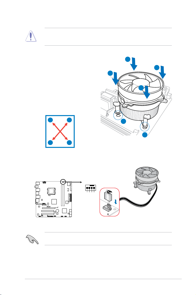
To install the CPU heatsink and fan:
1. Place the heatsink on top of the
installed CPU, making sure that the
B
A
B
four fasteners match the holes on
the motherboard.
A
2. Push down two fasteners at a time in
a diagonal sequence to secure the
heatsink and fan assembly in place.
A
B
B
1
1
A
3. When the fan and heatsink assembly is in place, connect the CPU fan cable
to the connector on the motherboard.
Do not forget to connect the CPU fan connector! Hardware monitoring errors
can occur if you fail to plug this connector.
2-7ASUS V-Series P5P43
Page 26
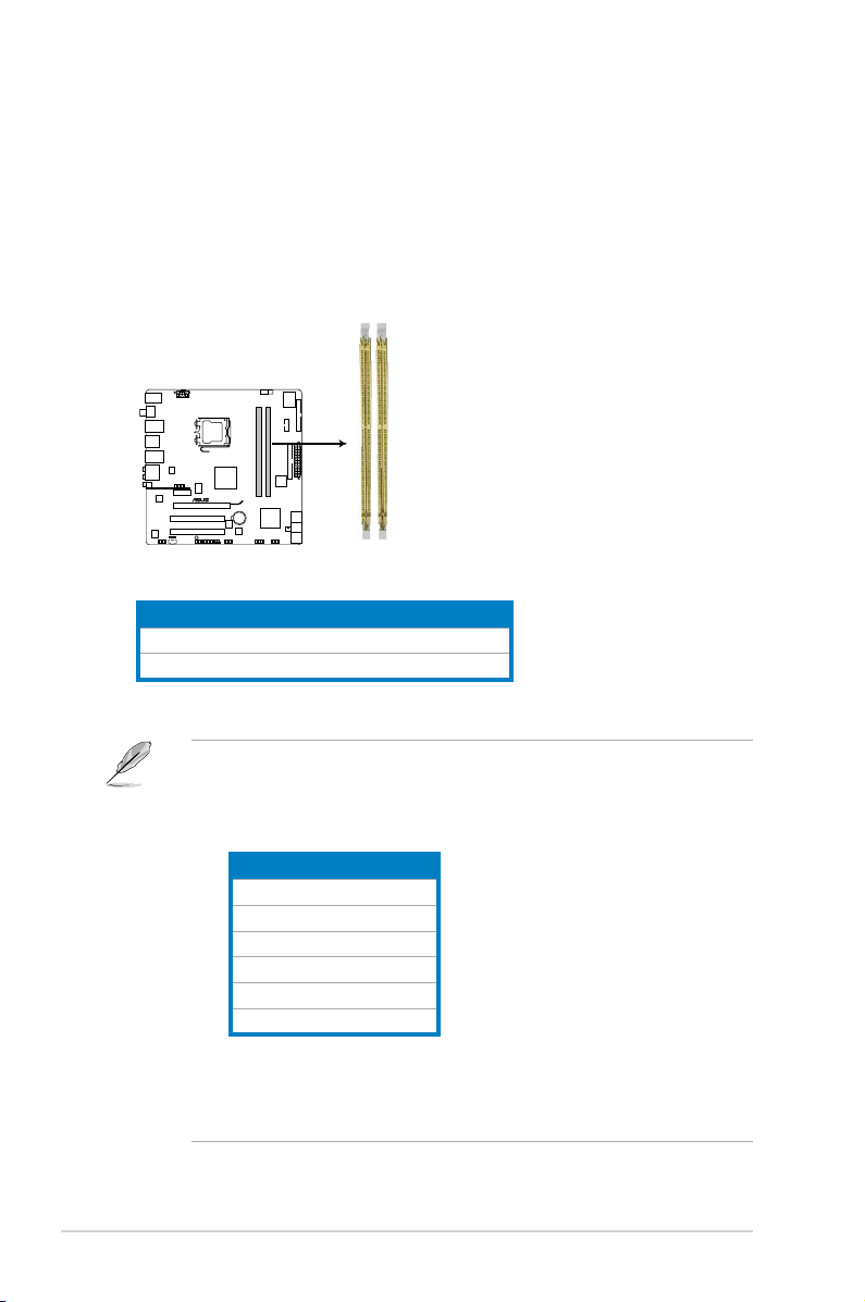
2.5 Installing a DIMM
P5QL-M DELUXE/WIFI-AP
P5QL-M DELUXE/WIFI-AP 240-pin DDR2 DIMM sockets
DIMM_A1
DIMM_B1
The motherboard comes with four Double Data Rate 2 (DDR2) Dual Inline Memory
Modules (DIMM) sockets.
The gure illustrates the location of the DDR2 DIMM sockets:
Channel Sockets
Channel A DIMM_A1
Channel B DIMM_B1
• This chipset ofcially supports DDR2-800 MHz. With the ASUS Super
Memspeed Technology, this motherboard natively supports up to
DDR2-1066 MHz. See the table below.
FSB DDR2
1333 1066*
1333 800
1333 667
1066 1066*
1066 800
1066 667
• *If you install a DDR2-1066 memory module whose SPD is DDR2-800,
make sure that you set the DRAM Frequency item in BIOS to
[DDR2-1066MHz]. See section 5.4.1JumperfreeConguration for
details.
2-8 Chapter 2: Basic installation
Page 27
2.5.1 Memorycongurations
You may install 256 MB, 512 MB, 1 GB,2 GB and 4GB unbuffered non-ECC DDR2
DIMMs into the DIMM sockets.
• You may install varying memory sizes in Channel A and Channel B. The
system maps the total size of the lower-sized channel for the dual-channel
conguration. Any excess memory from the higher-sized channel is then
mapped for single-channel operation.
• Always install DIMMs with the same CAS latency. For optimum compatibility,
we recommend that you obtain memory modules from the same vendor.
• Due to the memory address limitation on 32-bit Windows OS, when you
install 4GB or more memory on the motherboard, the actual usable memory
for the OS can be about 3GB or less. For effective use of memory, we
recommend that you install a 64-bit Windows OS when having 4GB or more
memory installed on the motherboard.
• This motherboard does not support DIMMs made up of 256 megabit (Mb)
chips or less.
Notes on memory limitations
• Due to chipset limitation, this motherboard can only support up to
8 GB on the operating systems listed below. You may install a maximum of
4 GB DIMMs on each slot.
64-bit
Windows® XP Professional x64 Edition
Windows® Vista x64 Edition
• Some old-version DDR2-800/667 DIMMs may not match Intel®’s
On-Die-Termination (ODT) requirement and will automatically downgrade
to run at DDR2-533. If this happens, contact your memory vendor to check
the ODT value.
• Due to chipset limitation, DDR2-800 with CL=4 will be downgraded to run
at DDR2-667 by default setting. If you want to operate with lower latency,
adjust the memory timing manually.
• Due to chipset limitation, DDR2-667 with CL=3 will be downgraded to run
at DDR2-533 by default setting. If you want to operate with lower latency,
adjust the memory timing manually.
2-9ASUS V-Series P5P43
Page 28

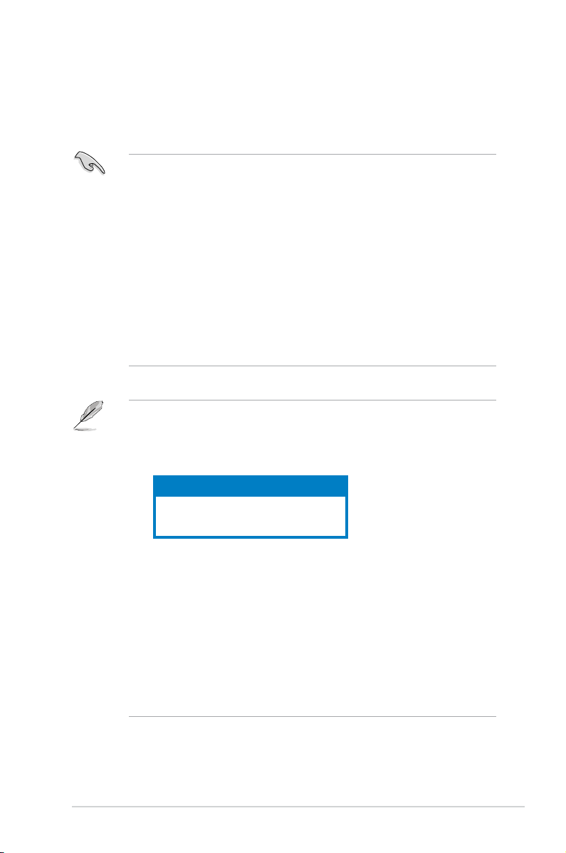
P5QL-MDelux/WiFi-APMotherboardQualiedVendorsLists(QVL)
DDR2667QualiedVendorsList
Vendor Part No. Size
Kingston KVR667D2N5/512 512MB SS N/A HY5PS12821EFP-Y5 Hynix • •
Kingston KVR667D2N5/1G 1G DS N/A HY5PS12821EFP-Y5 Hynix • •
Kingston KVR667D2N5/2G 2G DS N/A 7RE22 D9HNL Micron • •
Kingston KVR667D2N5/512 512MB SS N/A SO1237650821 SBP D6408TR4C
Kingston KVR667D2N5/2G 2G DS N/A E1108ACBG-8E-E 0813A90CC Elpida • •
Kingston KVR667D2N5/1G 1G DS N/A SO1280420822 SOP D6408TR4
Qimonda HYS64T64000EU-3S-B2 512MB SS 5 HYB18T512B00B2F3SFSS28171 Qimonda • •
Qimonda HYS64T128020EU-3S-B2 1G DS 5 HYB18T512B00B2F3SFSS28171 Qimonda • •
Corsair VS512MB667D2 512MB DS N/A MIII0052532M8CEC Corsair • •
Corsair VS1GB667D2 1G DS N/A MID095D62864M8CEC Corsair • •
Corsair XMS2-5400 1G DS 4 Heat-Sink Package Corsair • •
Micron MT8HTF12864AY-667E1 1G SS 5 D9HNL 7ZE17 Micron • •
HY HYMP512U64CP8-Y5 AB 1G DS 5 HY5PS12521CFP-Y5 Hynix • •
Kingmax KLCC28F-A8KB5 512MB SS N/A KKEA88B4LAUG-29DX Kingmax • •
Kingmax KLCD48F-A8KB5 1G DS N/A KKEA88B4LAUG-29DX Kingmax • •
Apacer AU512E667C5KBGC 512MB SS 5 AM4B5708MIJS7E0627B Apacer • •
Apacer AU512E667C5KBGC 512MB SS 5 AM4B5708GQJS7E06332F Apacer • •
Apacer 78.91G92.9K5 512MB SS 5 AM4B5708JQJS7E0751C Apacer • •
Apacer 78.01G9O.9K5 1G SS 5 AM4B5808CQJS7E0751C Apacer • •
Apacer AU01GE667C5KBGC 1G DS N/A AM4B5708GQJS7E0636B Apacer • •
Apacer AU01GE667C5KBGC 1G DS 5 AM4B5708MIJS7E0627B Apacer • •
Apacer 78.A1G9O.9K4 2G DS 5 AM4B5808CQJS7E0749B Apacer • •
Transcend 506010-4894 1G DS 5 E5108AJBG-6E-E Elpida • •
ADATA M2OAD5G3H3160Q1C52 512MB SS N/A AD29608A8A-3EG20813 ADATA • •
ADATA M2OAD5G314170Q1C58 1G DS N/A AD29608A8A-3EG80814 ADATA • •
ADATA M2OAD5H3J4170I1C53 2G DS N/A AD20908A8A-3EG 30724 ADATA • •
PSC AL6E8E63J-6E1 512MB SS 5 A3R12E3JFF717B9A00 PSC • •
PSC AL7E8E63J-6E1 1G DS 5 A3R12E3JFF717B9A01 PSC • •
PSC AL7E8F73C-6E1 1G SS 5 A3R1GE3CFF734MAA0J PSC • •
Nanya NT512T64U88A1BY-3C 512MB SS N/A NT5TU64M8AE-3C Nanya • •
Nanya NT1GT64U8HB0BY-3C 1G DS 5 NT5TU64M8BE-3C72155700CP Nanya • •
GEIL GX21GB5300SX 1G DS 3 Heat-Sink Package GEIL • •
GEIL GX22GB5300LX 2G DS 5 Heat-Sink Package GEIL • •
SS/
DS
CL Chip No.
GL25USL074905PECNB
CGL25USL156304PECXA
DIMM support
Chip
Brand
Kingston • •
Kingston • •
A* B*
(continued on the next page)
2-10 Chapter 2: Basic installation
Page 29

DIMM support
Chip
Brand
Talent
ELIXIR • •
A* B*
• •
of 2)
of 2)
SS/
CL Chip No.
DS
DS 5-5-
5-15
DS 5-5-
5-15
D2 64M8CCF 0815 C7173S G.SKILL • •
Heat-Sink Package G.SKILL • •
3C639009W1CF
Vendor Part No. Size
GEIL GX24GB5300LDC 2G DS 5 Heat-Sink Package GEIL • •
G.SKILL F2-5400PHU2-2GBNT 2G(kit
G.SKILL F2-5300CL5D-4GBMQ 4G(kit
Super Talent T667UB1GV 1G DS 5 PG 64M8-800 0750 Super
Twinmos 8D-A3JK5MPETP 512MB SS 5 A3R12E3GEF633ACAOY PSC • •
Samsung M378T5263AZ3-CE6 4G DS N/A K4T2G084QA-HCE6 Samsung • •
ELIXIR M2Y1G64TU8HA2B-3C 1G DS 5 M2TU51280AE-3C717095R28F ELIXIR • •
ELIXIR M2Y1G64TU8HBOB-3C 1G DS 5 N2TU51280BE-
Leadmax LRMP512U64A8-Y5 1G DS N/A HY5PS12821CFP-Y5 C 702AA Hynix • •
MDT DDRII 512 PC667 512MB DS 4 18D51201D-30726E MDT
MDT MDT 1024MB 1G DS 4 18D51280D-30646E MDT
AENEON AET660UD00-30DB97X 512MB SS 5 AET93R300B 0634 AENEON • •
AENEON AET760UD00-30DB97X 1G DS 5 AET93R300B 0639 AENEON •
AENEON AET860UD00-30DB08X 2G DS 5 AET03F30DB 0730 AENEON • •
TAKEMS TMS51B264C081-665QI 512MB SS 5 MS18T51280-3 takeMS • •
TAKEMS TMS51B264C081-665AP 512MB SS 5 MS18T51280-3S0627D takeMS • •
TAKEMS TMS1GB264C081-665QI 1G DS 5 MS18T51280-3 takeMS • •
TAKEMS TMS1GB264C081-665AE 1G DS 5 MS18T51280-3SEA07100 takeMS • •
TAKEMS TMS1GB264C081-665AP 1G DS 5 MS18T51280-3SP0717A takeMS • •
TEAM TVDD512M667C5 512MB SS N/A T2D648MT-6 TEAM •
TEAM TVDD1.02M667C4 1G DS N/A T2D648PT-6 TEAM
ASINT SLX264M8-J6E 512MB SS N/A DDRII6408-6E ASINT • •
ASINT SLY2128M8-J6E 1G SS N/A DDRII1208-6E 8115 ASINT • •
Century CENTURY 512MB 512MB SS N/A NT5TU64M8AE-3C Nanya •
Century CENTURY 512MB 512MB SS N/A HY5PS12821AFP-Y5 Hynix • •
Century CENTURY 1G 1G DS N/A HY5PS12821AFP-Y5 Hynix
Century CENTURY 1G 1G DS N/A NT5TU64M8AE-3C Nanya •
UMAX D46701GP3-63BJU 1G DS N/A U2S12D30YP-6E UMAX • •
UMAX D46702GP0-73BCU 2G DS 5 U2S24D30TP-6E UMAX • •
PQI DDR2-667U 1G 1G DS N/A HY5PS12821BFP-E3 A Hynix • •
KINGBOX 512MB 667MHz 512MB SS N/A EPD264082200-4 KINGBOX • •
KINGBOX DDRII 1G 667MHz 1G DS N/A EPD264082200-4 KINGBOX • •
2-11ASUS V-Series P5P43
Page 30

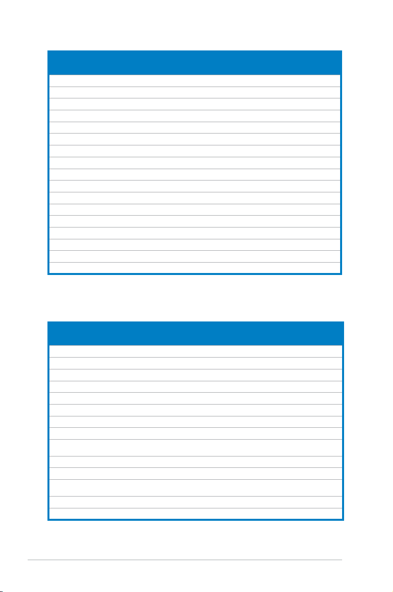
DDR2800QualiedVendorsList
Vendor Part No. Size
Kingston KHX6400D2LL/1G 1G DS N/A Heat-Sink Package Kingston • •
Kingston KHX6400D2LLK2/1GN 512MB SS N/A Heat-Sink Package Kingston • •
Kingston KVR800D2N5/512 512MB SS N/A V59C1512804QCF25SY032
Kingston KVR800D2N5/1G 1G DS N/A V59C1512804QCF25S0061
Kingston KHX6400D2K2/2G 1G(Kit of 2) DS N/A Heat-Sink Package Kingston • •
Kingston KVR800D2N6/512 512MB SS N/A E5108AJBG-8E-E Elpida • •
Kingston KVR800D2N5/1G 1G DS N/A E5108AJBG-8E-E Elpida • •
Kingston KVR800D2N6/1G 1G DS N/A E5108AJBG-8E-E Elpida • •
Kingston KVR800D2N5/2G 2G DS N/A E1108ACBG-8E-E Elpida • •
Kingston KHX6400D2/2G 2G DS N/A Heat-Sink Package Kingston • •
Kingston KVR800D2N6/4G 4G DS N/A E2108ABSE-8G-E Elpida • •
Kingston KVR800D2N5/512 512MB SS N/A E5108AJBG-8E-E
Samsung M378T6553GZS-CF7 512MB SS 6 K4T51083QG-HCF7 Samsung • •
Samsung M378T2863QZS-CF7 1G SS 6 K4T1G084QQ-HCF7 Samsung • •
Samsung M378T2953GZ3-CF7 1G DS 6 K4T51083QG-HCF7 Samsung • •
Samsung M37875663QZ3-CF7 2G DS 6 K4T1G084QQ-HCF7 Samsung • •
Samsung M378T5263AZ3-CF7 4G DS N/A K4T2G084QA-HCF7 Samsung • •
Qimonda HYS64T64000EU-2.5-B2 512MB SS 6 HYB18T512800B2F25FS
Qimonda HYS64T128020EU-
2.5-B2
Corsair CM2X1024-6400 1G DS 4 Heat-Sink Package Corsair • •
Corsair XMS2-6400 1G DS 4 Heat-Sink Package Corsair • •
Corsair XMS2-6400 1G DS 5 Heat-Sink Package Corsair • •
Corsair CM2X2048-6400C5DHX 2G(Kit of 2) DS 5 Heat-Sink Package Corsair • •
Corsair CM2X2048-6400C5 2G(Kit of 2) DS 5 Heat-Sink Package Corsair • •
Crucial BL12864AL804.8FE5 2G(Kit of 2)(EPP) SS 4 Heat-Sink Package N/A • •
Crucial BL12864AA804.8FE5 2G(Kit of 2)(EPP) SS N/A Heat-Sink Package N/A • •
HY HYMP564U64CP8-
S5 AB
HY HYMP512U64CP8-
S5 AB
Kingmax KLDC28F-A8KI5 512MB SS N/A KKA8FF1XF-JFS-25A Kingmax • •
Apacer 78.91G91.9K5 512MB SS 5 AM4B5708JQJS8E0751C Apacer • •
Apacer 78.01GA0.9K5 1G SS 5 AM4B5808CQJS8E0749D Apacer • •
Apacer 78.A1GA0.9K4 2G DS 5 AM4B5808CQJS8E0740E Apacer • •
Apacer 78.A1GA0.9K4 2G DS 5 AM4B5808CQJS8E0747D Apacer • •
Transcend 503499-7280 1G DS 5 7NB32 D9DCL Mircon • •
Transcend TS128MLQ64V8J 1G DS 5 7HD22D9GMH Mircon • •
1G DS 6 HYB18T512800B2F25FS
512MB SS 5 HY5PS12821CFP-S5 Hynix • •
1G DS 5 HY5PS12821CFPS5 Hynix • •
SS/
DS
CL Chip No.
406PECPA
904PECJA
0803A9082
S28380
S28380
DIMM support
Chip
Brand
Promos • •
Promos • •
Kingston • •
Qimonda • •
Qimonda • •
A* B*
(continued on the next page)
2-12 Chapter 2: Basic installation
Page 31

Vendor Part No. Size
Transcend TS64MLQ64V8J512MB 512MB SS 5 7HD22 D9GMH Micron • •
Transcend TS128MLQ64V8J 1G DS 5 TQ123PJF8F0801 Transcend • •
ADATA M2OAD6G3H3160Q1E58 512MB SS N/A AD29608A8A-25EG80812 ADATA • •
VDATA M2GVD6G3H3160Q1E52 512MB SS N/A VD29608A8A-25EG20813 VDATA • •
ADATA M2OAD6G314170Q1E58 1G DS N/A AD29608A8A-25EG80810 ADATA • •
VDATA M2GVD6G314170Q1E58 1G DS N/A VD29608A8A-25EG80813 VDATA • •
PSC AL7E8F73C-8E1 1G SS 5 A3R1GE3CFF734MAA0E PSC • •
PSC AL8E8F73C-8E1 2G DS 5 A3R1GE3CFF734MAA0E PSC • •
GEIL GB22GB6400C4DC 1G DS 4 GL2L64M088BA30EB GEIL • •
GEIL GB24GB6400C4QC 1G DS 4 GL2L64M088BA30EB GEIL • •
GEIL GB22GB6400C5DC 1G DS 5 GL2L64M088BA30EB GEIL • •
GEIL GB24GB6400C5QC 1G DS 5 GL2L64M088BA30EB GEIL • •
GEIL GX22GB6400DC 1G DS 5 Heat-Sink Package GEIL • •
GEIL GE22GB800C4DC 1G DS 4 Heat-Sink Package GEIL • •
GEIL GE24GB800C4QC 1G DS 4 Heat-Sink Package GEIL • •
GEIL GX22GB6400UDC 1G DS 4 Heat-Sink Package GEIL • •
GEIL GE22GB800C5DC 1G DS 5 Heat-Sink Package GEIL • •
GEIL GE24GB800C5QC 1G DS 5 Heat-Sink Package GEIL • •
GEIL GB24GB6400C4DC 2G DS 4 GL2L128M88BA25AB GEIL • •
GEIL GB24GB6400C5DC 2G DS 5 GL2L128M88BA25AB GEIL • •
GEIL GB28GB6400C5QC 2G DS 5 GL2L128M88BA25AB GEIL • •
GEIL GB28GB6400C4QC 2G DS 4 GL2L128M88BA25AB GEIL • •
GEIL GX22GB6400LX 2G DS 5 Heat-Sink Package GEIL • •
GEIL GX24GB6400DC 2G DS 5 Heat-Sink Package GEIL • •
GEIL GE28GB800C5QC 2G DS 5 Heat-Sink Package GEIL • •
GEIL GE28GB800C4QC 2G DS 4 Heat-Sink Package GEIL • •
GEIL GX22GB6400CUSC 2G DS 4 Heat-Sink Package GEIL • •
GEIL GE24GB800C4DC 2G DS 4 Heat-Sink Package GEIL • •
GEIL GE24GB800C5DC 2G DS 5 Heat-Sink Package GEIL • •
Super Talent T800UB1GC4 1G DS 4 Heat-Sink Package Super Talent • •
G.SKILL F2-6400CL5D-2GBNQ 1G DS 5 Heat-Sink Package G.SKILL • •
G.SKILL F2-6400CL4D-2GBPK 1G DS 4 Heat-Sink Package G.SKILL • •
G.SKILL F2-6400CL4D-2GBHK 1G DS 4 Heat-Sink Package G.SKILL • •
G.SKILL F2-6400CL5D-4GBPQ 2G DS 5 Heat-Sink Package G.SKILL • •
G.SKILL F2-6400CL4D-4GBPK 2G DS 4 Heat-Sink Package G.SKILL • •
G.SKILL F2-6400CL5Q-16GNQ 4G DS 5 Heat-Sink Package G.SKILL • •
G.SKILL F2-6400CL5D-1GBNQ 512MB(Kit
OCZ OCZ2RPR8002GK 1G DS 4 Heat-Sink Package OCZ • •
OCZ OCZ2G800R22GK 1G DS 5 Heat-Sink Package OCZ • •
of 2)
SS/
CL Chip No. Chip Brand
DS
SS 5-5-
Heat-Sink Package G.SKILL • •
5-15
DIMM support
A* B*
(continued on the next page)
2-13ASUS V-Series P5P43
Page 32
Vendor Part No. Size
OCZ OCZ2P800R22GK 1G DS 4 Heat-Sink Package OCZ • •
OCZ OCZ2VU8004GK 1G DS 6 Heat-Sink Package OCZ • •
OCZ OCZ2P8004GK 2G DS 5 Heat-Sink Package OCZ • •
Elixir M2Y1G64TU8HB0B-25C 1G DS 5 N2TU51280BE-25C802006Z1DV Elixir • •
AENEON AET660UD00-25DB98X 512MB SS N/A AET93F25DB 0621 AENEON • •
AENEON AET760UD00-25DB97X 1G DS 5 AET93R25DB 0640 AENEON
AENEON AET760UD00-25DC08X 1G SS 5 AET03R250C 0732 AENEON • •
AENEON AET860UD00-25DC08X 2G DS 5 AET03R250C 0732 AENEON • •
MDT MDT 512MB 512MB SS 5 18D51280D-2.50726F MDT • •
MDT MDT 1024MB 1G DS 5 18D51280D-2.50726E MDT • •
Century 28V0H8 1G DS 5 HY5PS12821CFP-S5 Hynix
TAKEMS TMS51B264C081-805EP 512MB SS 5 MS18T51280-2.5P0710 takeMS • •
TAKEMS TMS1GB264C081-805EP 1G DS 5 MS18T51280-2.5P0716 takeMS • •
ASINT SLY2128M8-JGE 1G SS N/A DDRII1208-GE 8115 ASINT • •
ASINT SLZ2128M8-JGE 2G DS N/A DDRII1208-GE 8115 ASINT • •
UMAX D48001GP3-63BJU 1G DS N/A U2S12D30TP-8E UMAX •
UMAX D48002GP0-73BCU 2G DS 5 U2S24D30TP-8E UMAX •
SS/
CL Chip No.
DS
Chip
Brand
DIMM support
A* B*
DDR21066QualiedVendorsList
Vendor Part No. Size
Kingston KHX8500D2/512 512MB SS N/A Heat-Sink Package Kingston •
Kingston KVR1066D2N7/512 512MB SS N/A E5108AJBG-1J-E Elpida • •
Kingston KHX8500D2K2/1GN 512MB SS N/A Heat-Sink Package Kingston • •
Kingston KHX8500D2K2/2GN 1G DS N/A Heat-Sink Package Kingston
Kingston KHX8500D2/1G 1G DS N/A Heat-Sink Package Kingston
Qimonda HYS64T128020EU-19F-C 1G DS 6 HYB18T512800CF19FFSS24313 Qimonda • •
Kingmax KLED48F-A8K15 1G DS N/A KKA8FFIXF-JFS-18A Kingmax •
Corsair CM2X1024-8500C5 1G DS N/A Heat-Sink Package N/A • •
Corsair CM2X1024-8500C5D 1G SS 5-5-
Transcend TX1066QLJ-2GK1GB 1G DS 5 Heat-Sink Package Transced •
Transcend TX1066QLU-2GK 4G(kit of 2) SS 5 Heat-Sink Package Transced • •
OCZ OCZ2N1066SR2DK 2G(kit of 2) DS 5-5-
GEIL GB22GB8500C5DC 1G SS 5 GL2L128M88BA25AB GEIL
GEIL GB24GB8500C5QC 1G SS 5 GL2L128M88BA25AB GEIL • •
SS/
DS
CL Chip No.
Heat-Sink Package NA • •
5-15
Heat-Sink Package(EPP) OCZ
5-15
Chip
Brand
DIMM support
A* B*
(continued on the next page)
2-14 Chapter 2: Basic installation
Page 33

Vendor Part No. Size
GEIL GE22GB1066C5DC 1G SS 5 Heat-Sink Package GEIL •
GEIL GE24GB1066C5QC 1G SS 5 Heat-Sink Package GEIL
GEIL GB24GB8500C5DC 2G DS 5 GL2L128M88BA25AB GEIL •
GEIL GE24GB1066C5DC 2G DS 5 Heat-Sink Package GEIL • •
GEIL GX24GB8500C5UDC 4G(kit of 2) DS 5 Heat-Sink Package N/A
G.SKILL F2-8500CL5D-2GBPK 2G(kit of 2) DS 5-5-5-15 Heat-Sink Package N/A • •
G.SKILL F2-8500CL5D-4GBPK 4G(kit of 2) DS 5-5-5-15 Heat-Sink Package N/A •
G.SKILL F2-8500CL5S-1GBPK 1G DS 5-5-5-15 Heat-Sink Package G.SKILL • •
Kingbox EP512D21066PS 512MB SS N/A 6QD22D9GCT Micron • •
AENEON AXT760UD00-19DC97X 1G DS 5 Heat-Sink Package AENEON
AENEON AXT860UD20-19E 2G DS 5 Heat-Sink Package AENEON •
SS/
CL Chip No.
DS
Chip
Brand
DIMM support
A* B*
SS - Single-sided / DS - Double - sided
DIMM support:
• A*: Supports one module inserted into any slot as Single-channel memory
conguration.
• B*: Supports one pair of modules inserted into the yellow as one pair of
Dual-channel memory conguration.
Visit the ASUS website for the latest DDR2-667/800/1066 MHz QVL.
2-15ASUS V-Series P5P43
Page 34

2.5.2 Installing a DDR2 DIMM
Make sure to unplug the power supply before adding or removing DIMMs or
other system components. Failure to do so may cause severe damage to both
the motherboard and the components.
1. Unlock a DDR2 DIMM socket
by pressing the retaining clips
outward.
2. Align a DIMM on the socket
such that the notch on the DIMM
matches the break on the socket.
Unlocked retaining clip
A DDR2 DIMM is keyed with a notch so that it ts in only one direction. DO
NOT force a DIMM into a socket to avoid damaging the DIMM.
2
DDR2 DIMM notch
1
1
3. Firmly insert the DIMM into the
3
socket until the retaining clips snap
back in place and the DIMM is
properly seated.
Locked Retaining Clip
2.5.3 Removing a DDR2 DIMM
Follow these steps to remove a DIMM.
1. Simultaneously press the
retaining clips outward to unlock
the DIMM.
1
Support the DIMM lightly with your ngers when pressing the retaining clips.
The DIMM might get damaged when it ips out with extra force.
2. Remove the DIMM from the socket.
2-16 Chapter 2: Basic installation
2
1
DDR2 DIMM notch
Page 35

2.6 Expansion slots
In the future, you may need to install expansion cards. The following sub-sections
describe the slots and the expansion cards that they support.
Make sure to unplug the power cord before adding or removing expansion
cards. Failure to do so may cause you physical injury and damage motherboard
components.
2.6.1 Installing an expansion card
To install an expansion card:
1. Before installing the expansion card, read the documentation that came with
it and make the necessary hardware settings for the card.
2. Remove the system unit cover (if your motherboard is already installed in a
chassis).
3. Remove the bracket opposite the slot that you intend to use. Keep the screw
for later use.
4. Align the card connector with the slot and press rmly until the card is
completely seated on the slot.
5. Secure the card to the chassis with the screw you removed earlier.
6. Replace the system cover.
2.6.2 Conguringanexpansion card
After installing the expansion card, congure it by adjusting the software settings.
1. Turn on the system and change the necessary BIOS settings, if any. See
Chapter 5 for information on BIOS setup.
2. Assign an IRQ to the card. Refer to the tables on the next page.
3. Install the software drivers for the expansion card.
When using PCI cards on shared slots, ensure that the drivers support “Share
IRQ” or that the cards do not need IRQ assignments. Otherwise, conicts will
arise between the two PCI groups, making the system unstable and the card
inoperable.
2-17ASUS V-Series P5P43
Page 36

Interrupt assignments
IRQ Standard Function
0 System Timer
1 Standard 101/102-Key or Microsoft Natural Keyboard
2 Free
3 Free
4 Communications Port (COM1)
5 Free
6 Standard oppy
7 Free
8 System CMOS/real time clock
9 Microsoft acpi-Compliant system
10 Free
11 Free
12 Free
13 Numeric data processor
14 Free
15 Intel® ICH10Family SMBus Controller-3A30
2-18 Chapter 2: Basic installation
Page 37

IRQ assignments for this motherboard
A B C D E F G H
PCIE X 1 slot shared shared shared shared — — — —
PCIE X 16 slot shared shared shared shared — — — —
Onboard USB 1.1 controller 1 — — — — — — — shared
Onboard USB 1.1 controller 2 — — — shared — — — —
Onboard USB 1.1 controller 3 — — shared — — — — —
Onboard USB 1.1 controller 4 shared — — — — — — —
Onboard USB 1.1 controller 5 shared — — — — — — —
Onboard USB 1.1 controller 6 — — — — — shared — —
Onboard USB 1.1 controller 7 — — shared — — — — —
Onboard USB 2.0 controller 1 — — — — — — — shared
Onboard USB 2.0 controller 2 — — shared — — — — —
PCIe Stroage Controller shared — — — — — — —
Onboard HD audio — — — — — — shared —
Onboard LAN 1 — used — — — — — —
Onboard LAN 2 — — used — — — — —
Onboard 1394 controller — — — used — — — —
Onchip SATA 1 — — used used — — — —
Onchip SATA 2 — — — used — — — —
PCI slot 1 shared shared shared shared — — — —
PCI slot 2 shared shared shared shared — — — —
2-19ASUS V-Series P5P43
Page 38
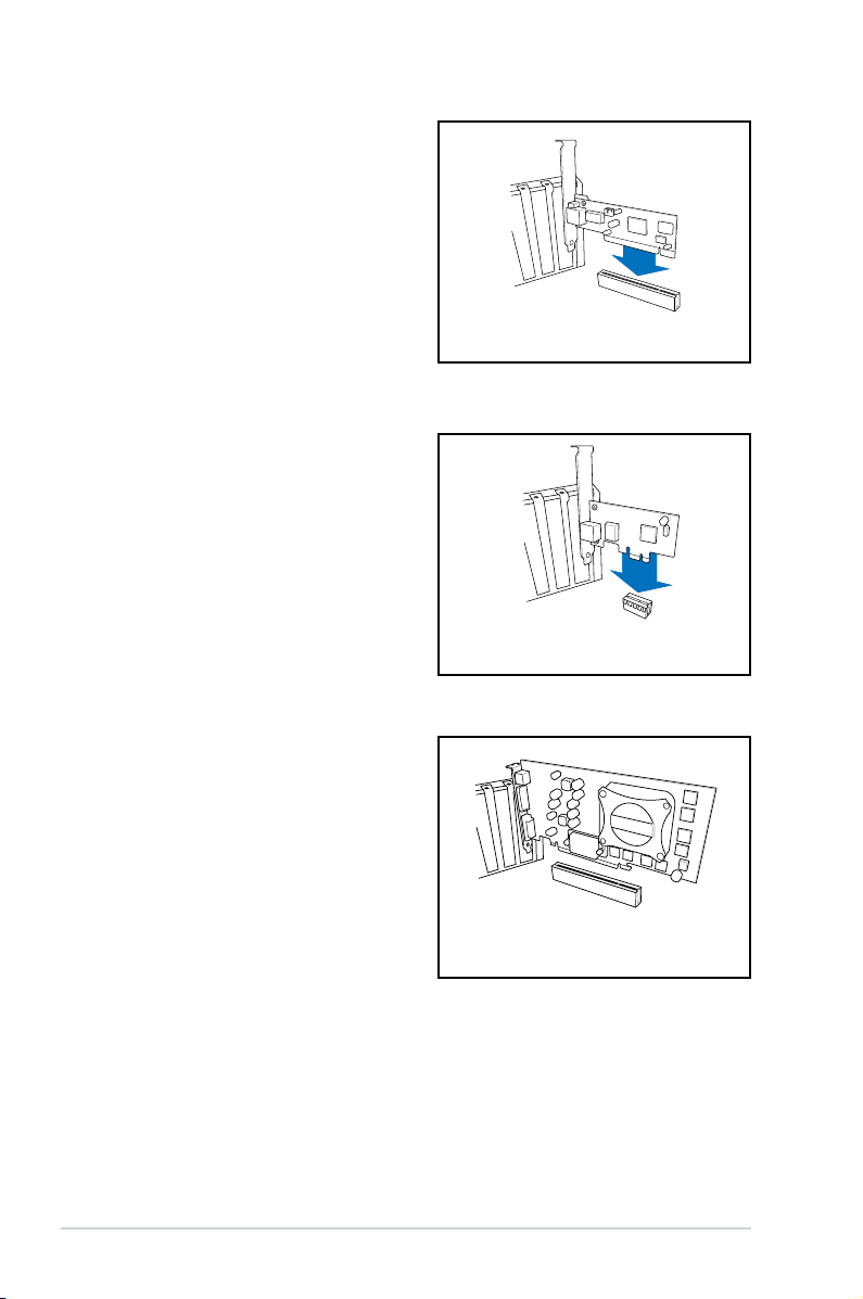
2.6.3 PCI slots
The PCI slots support cards such as
a LAN card, SCSI card, USB card,
and other cards that comply with PCI
specications. The gure shows a LAN
card installed on a PCI slot.
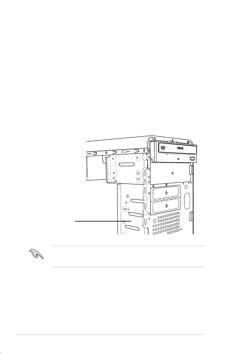
2.6.4 PCI Express x1 slot
This motherboard supports PCI Express
x1 network cards, SCSI cards and
other cards that comply with the PCI
Express specications. The gure shows
a network card installed on the PCI
Express x1 slot.
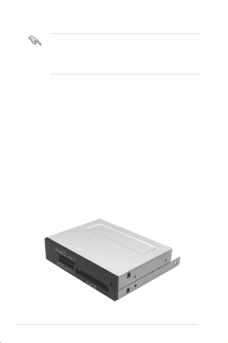
2.6.5 PCI Express x16 slot
This motherboard supports PCI Express
x16 graphic cards that comply with the
PCI Express specications. The gure
shows a graphics card installed on the
PCI Express x16 slot.
2-20 Chapter 2: Basic installation
Page 39

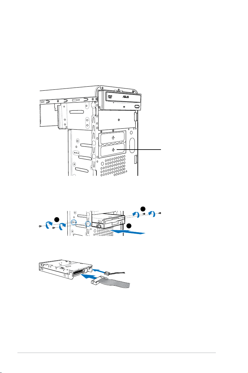
2.7 Installing an optical drive
4
4
3
Refer to the instructions in this section if you wish to install a new optical drive.
Follow these steps to install an optical drive:
1. Place the chassis upright.
2. Remove the drive slot metal plate cover.
3. Insert the optical drive into the upper 5.25-inch drive bay and carefully push
the optical drive into the bay until its screw holes align with the holes on the
bay as shown.
4. Secure the optical drive with two screws on both sides of the bay.
5. Connect a power cable from
the power supply to the power
connector at the back of the optical
drive.
6. Connect one end of the IDE ribbon
cable to the IDE interface at the
back of the optical drive, matching
the red stripe on the cable with Pin
1 on the IDE interface.
IDE ribbon cable
Power cable
2-21ASUS V-Series P5P43
Page 40
7. Connect the other end of the IDE ribbon cable to the secondary IDE
connector (labeled SEC_IDE) on the motherboard. See page 4-7 for the
location of this connector.
8. Remove the dummy drive slot cover from the front panel.
9. Replace the front panel.
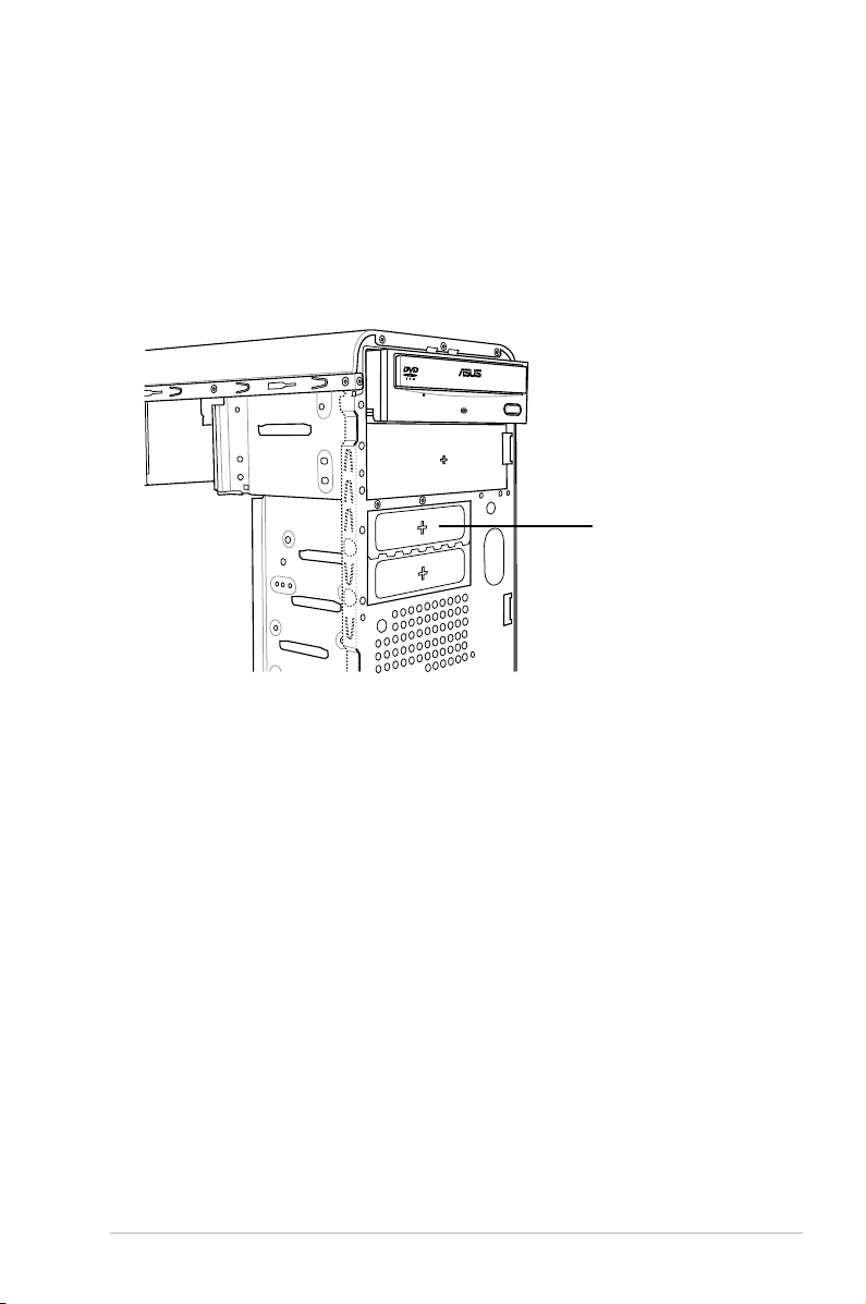
2.8 Installing a hard disk drive
To install a Serial ATA hard disk drive:
1. Carefully place the hard disk into the the lowest 3.5-inch drive slot (without
the metal plate cover).
2. Fasten the screws to secure the hard disk to the drive slot.
the lowest 3.5-inch
drive slot without
the metal plate
cover
If you do not need to install the optional card reader into your system, you can
install the HDD in the one of the 3.5-inch external bay (with the metal plate
cover).
3. Connect one end of the Serial ATA cable to the SATA connector at the back
of the drive, then connect the other end to a Serial ATA connector on the
motherboard. See page 4-6 for the location of the Serial ATA connectors.
2-22 Chapter 2: Basic installation
Page 41

4. Connect a 15-pin Serial ATA power plug from the power supply unit to the
15-pin power connector at the back of the drive.
- OR -
Connect a 4-pin (female) power plug from the power supply unit to the 4-pin
(male) power connector at the back of the drive.
Serial ATA power
cable
If your Serial ATA HDD has both 4-pin and 15-pin connectors at the back,
use either the 15-pin SATA power adapter plug OR the legacy 4-pin power
connector. DO NOT use both to prevent damage to components and to keep
the system from becoming unstable.
Serial ATA cable
To install an IDE hard disk drive:
1. Follow steps 1-2 of the previous section.
2. Connect the blue interface of the IDE ribbon cable to the primary IDE
connector (blue connector labeled PRI_IDE) on the motherboard. See page
4-7 for the location of the connector.
IDE ribbon cable
Power cable
2-23ASUS V-Series P5P43
Page 42
• If you will install only one hard disk drive, make sure to congure your hard
disk drive as Master device before connecting the IDE cable and power
plug. Refer to the HDD documentation on how to set the drive as a Master
device.
• If you will install two IDE hard disk drives, congure the other device as
Slave.
3. Connect the gray interface of the IDE ribbon cable to the IDE connector on
the drive.
4. If you install two IDE hard disk drives, connect the black interface of the IDE
ribbon cable to the IDE connector on the second (Slave) IDE hard disk drive.
5. Connect a 4-pin power plug from the power supply unit to the power
connector at the back of the drive(s).
2.9 Installing the card reader
An optional card reader module (see the gure below) is available with the system.
If you want to install the card reader into your system, follow the steps on the next
page.
Note: the card reader is optional and users need to purchase separately.
2-24 Chapter 2: Basic installation
Page 43
To install the card reader module:
1. Remove the drive slot metal plate cover.
2. Carefully insert the card reader module into the 3.5-inch bay until the screw
holes align with the holes on the bay.
3. Secure the card reader module with two screws on both sides.
remove the metal
plate cover and
install the card
reader module here
4. Connect the USB cable of the card reader to the USB connector on the
motherboard.
2-25ASUS V-Series P5P43
Page 44
2.10 Installingaoppydiskdrive
3
3
2
3
The system comes with one 3.25-inch drive bay for a oppy disk drive.
To install a oppy disk drive:
1. Remove the drive slot metal plate cover.
remove the metal
plate cover and
install the card
reader module here
2. Carefully insert the oppy disk drive into the oppy drive bay until the screw
holes align with the holes on the bay.
3. Secure the oppy disk drive with two screws on both sides.
4. Connect the oppy disk drive signal cable to the signal connector at the back
of the drive.
Power cable
Floppy ribbon cable
5. Connect the other end of the signal cable to the oppy disk drive connector
on the motherboard. See page 4-6 for the location of the oppy disk drive
connector.
6. Connect a 4-pin power cable from the power supply unit to the power connector
at the back of the oppy disk drive.
2-26 Chapter 2: Basic installation
Page 45
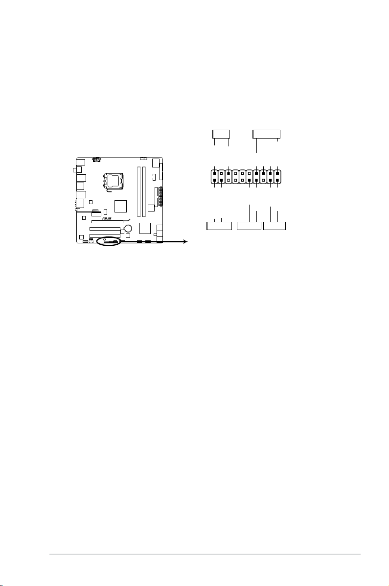
2.11 Re-connecting cables
P5QL-M DELUXE/WIFI-AP
P5QL-M DELUXE/WIFI-AP System panel connecto
r
PIN 1
* Requires an ATX power supply
PLED SPEAKER
PLED+
PLED-
+5V
Ground
Ground
Speaker
IDE_LED+
IDE_LED-
PWR
Ground
Reset
Ground
PANEL
IDE_LED PWRSW RESET
You may have disconnected some cables when you were installing components.
You must re-connect these cables before you replace the chassis cover.
Connect the reset button, power switch, power LED, and HDD LED cables to their
respective leads in the system panel connector on the motherboard.
2-27ASUS V-Series P5P43
Page 46

2.12 Reinstalling the cover
If you installed an optical and/or oppy disk drive, remove the bay cover(s) on the
front panel assembly before reinstalling it to the chassis. To do this:
1. Locate the bay cover locks.
2. Press the locks outward to release
the bay cover.
3. Push the bay cover inward, then set
it aside.
4. Follow the same instructions to
remove the 3.5” drive bay cover.
To reinstall the front panel assembly and side cover:
1. Insert the front panel assembly hinge-like tabs to the holes on the right side
of the chassis.
2. Swing the front panel assembly to the left, then insert the hooks to the
chassis until the front panel assembly ts in place.
3. Insert the six side cover hooks into the chassis tab holes .
4. Push the side cover to the direction of the front panel until it ts in place.
5. Secure the cover with two screws you removed earlier.
If the air duct interferes with the CPU fan, adjust the air duct accordingly.
2
5
4
5
Air duct
3
Chassis tab holes
2-28 Chapter 2: Basic installation
2
2
1
1
1
2
Page 47

Chapter 3
R
R
This chapter helps you power up the
system and install drivers and utilities
from the support DVD.
Starting up
Page 48
3.1 Installing an operating system
R
The barebone system supports Windows® XP/Vista operating systems (OS).
Always install the latest OS version and corresponding updates so you can
maximize the features of your hardware.
Because motherboard settings and hardware options vary, use the setup
procedures presented in this chapter for general reference only. Refer to your
OS documentation for more information.
• If Windows XP OS setup cannot recognize Serial ATA hard drives without
the necessary drivers. Use the bundled oppy disk when installing
Windows XP OS to a Serial ATA hard drive.
• From the Windows XP setup screen, press F6 when prompted then follow
succeeding screen instructions to install the SATA drivers.
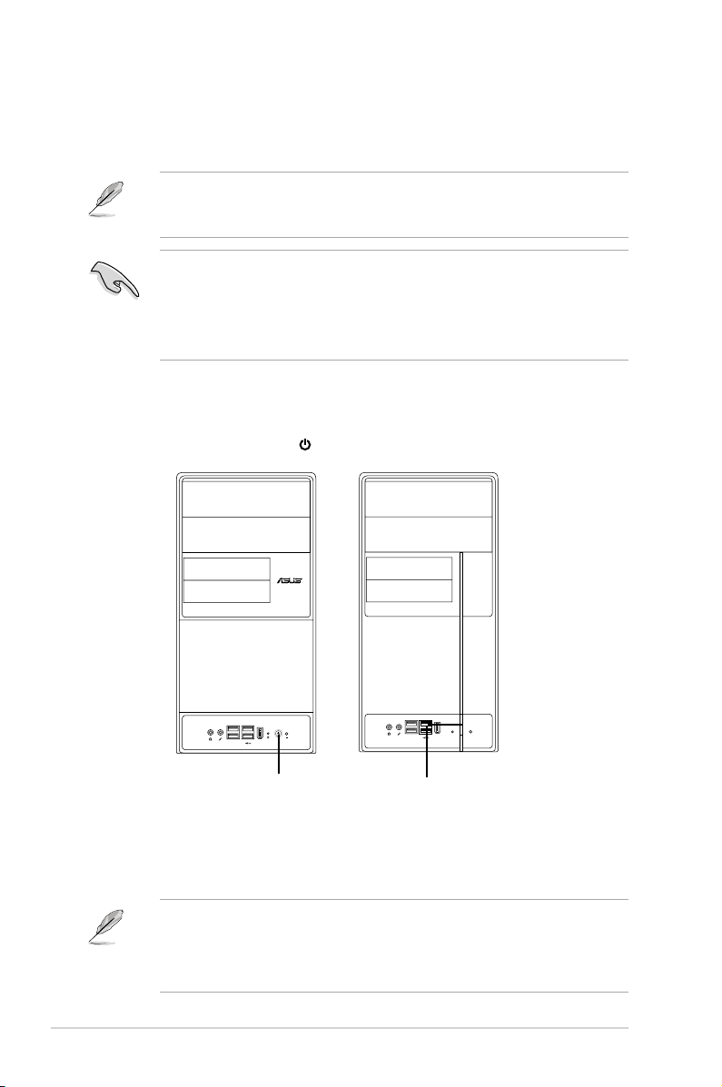
3.2 Powering up
Press the system power button ( ) to enter the OS.
Press to turn ON the system
3.3 Support DVD information
The support DVD that came with the system contains useful software and several
utility drivers that enhance the system features.
•
Screen display and driver options may not be the same for different
operating system versions.
•
The contents of the support DVD are subject to change at any time without
notice. Visit the ASUS website for updates.
3-2 Chapter 3: Starting up
Page 49

3.3.1 Running the support DVD
To begin using the support DVD, place the DVD in your optical drive. The DVD
automatically displays the Drivers menu if Autorun is enabled in your computer.
Click an icon to
display support
DVD/motherboard
information
Click an item to install
If Autorun is NOT enabled in your computer, browse the contents of the support
DVD to locate the le ASSETUP.EXE from the BIN folder. Double-click the
ASSETUP.EXE to run the DVD.
ASUS InstAll-Installation Wizard for Anti-Virus and Drivers Utility
Launches the ASUS InstAll driver installation wizard.
Norton Internet Security 2008
Installs the Norton Internet Security 2008.
Intel Chipset Inf Update Program
Installs the Intel® chipset Inf update program.
Realtek RTL8111B/C 10/100/1000M LAN Driver
Installs the Realtek® RTL8111B/C 10/100/1000M LAN Driver.
ASUS EPU-4 Engine
Installs the ASUS EPU-4 Engine.
ASUS WiFi-AP Solo
Installs the ASUS WiFi-AP Solo.
3-3ASUS V-Series P5P43
Page 50

JMicron JMB363 Controller Driver
Installs the JMcron JM363 Controller Driver.
NVIDIA EN9500GT Display Driver
Installs the NVIDIA EN9500GT display Driver.
ASUS Express Gate Installer
Installs ASUS Express Gate Installer.
3.3.2 Utilities menu
The Utilities menu shows the applications and other software that the motherboard
supports.
ASUS InstAll-Installation Wizard for Utilities
Installs all of the utilities through the Installation Wizard.
ASUS Update
Allows you to download the latest version of the BIOS from the ASUS website.
Before using the ASUS Update, make sure that you have an Internet connection
so you can connect to the ASUS website.
3-4 Chapter 3: Starting up
Page 51

ASUS PC Probe II
This smart utility monitors the fan speed, CPU temperature, and system voltages,
and alerts you of any detected problems. This utility helps you keep your computer
in healthy operating condition.
Adobe Acrobat Reader 8
Installs the Adobe® Acrobat® Reader that allows you to open, view, and print
documents in Portable Document Format (PDF).
Microsoft DirectX 9.0c
Installs the Microsoft® DirectX 9.0c driver. The Microsoft DirectX® 9.0c is a
multimedia technology that enhances computer graphics and sound. DirectX®
improves the multimedia features of you computer so you can enjoy watching
TV and movies, capturing videos, or playing games in your computer. Visit the
Microsoft website (www.microsoft.com) for updates.
Corel MediaOne Starter
Installs the Corel MediaOne Starter application to easily manage, edit share and
protect your multimedia data.
CyberLink PowerBackup
Installs CyberLink PowerBackup to back up and restore your data easily.
Realtek Diagnostics Utility
Installs the Realtek® diagnostics utility
WinZip 11
Installs the Winzip utility for easy le-compression and protection.
Ulead Burn. Now
Installs the Ulead Burn. Now application for Audio DVD,CD and data disc creation.
You can also install the following utilities from the ASUS Superb Software
Library DVD.
3-5ASUS V-Series P5P43
Page 52

Ulead Photolmpact 12 SE
Installs the Photolmpact image editing software.
3-6 Chapter 3: Starting up
Page 53

3.3.3 Manual menu
The Manual menu contains a list of supplementary user manuals. Click an item to
open the folder of the user manual.
Most user manual les are in Portable Document Format (PDF). Install the
Adobe® Acrobat® Reader from the ASUS Superb Software Library DVD before
opening a user manual le.
Realtek HD Audio User’s Manual
Allows you to open the Realtek HD audio user’s manual.
Intel® Matrix Stroage Manager User’s Manual
Allows you to open the Intel® Matrix stroage manager user’s manual.
ASUS Motherboard Installation Guide
Allows you to open the ASUS Motherboard Installation Guide.
NIS 2008 Subscription Renewal Guide
Allows you to open the NIS 2008 Subscription Renewal Guide.
3-7ASUS V-Series P5P43
Page 54

3.3.4 Make Disk menu
The Make Disk menu allows you to make a RAID driver disk.
Make JMicron JMB363 RAID/AHCI Controller Driver disk
Allows you to create a JMicron JMB363 RAID/AHCI Controller driver disk
Make Intel® ICH10R RAID/AHCI Controller Driver disk
Allows you to create a JMicron JMB363 RAID/AHCI Controller driver disk
3-8 Chapter 3: Starting up
Page 55

3.3.5 ASUS Contact information
Click the Contact tab to display the ASUS contact information. You can also nd
this information on the inside front cover of this user guide.
3-9ASUS V-Series P5P43
Page 56

3.3.6 Other information
The icons on the top right corner of the screen give additional information on the
motherboard and the contents of the support DVD. Click an icon to display the
specied information.
Motherboard Info
Displays the general specications of the motherboard.
Browse this DVD
Displays the support DVD contents in graphical format.
3-10 Chapter 3: Starting up
Page 57

Technical support Form
Displays the ASUS Technical Support Request Form that you have to ll out when
requesting technical support.
Filelist
Displays the contents of the support DVD and a brief description of each in text
format.
3-11ASUS V-Series P5P43
Page 58

3.4 Software information
Most of the applications in the support DVD have wizards that will conveniently
guide you through the installation. View the online help or readme le that came
with the software for more information.
ASUS PC Probe II
PC Probe II is a utility that monitors the computer’s vital components and alerts
you of any problem with these components. PC Probe II senses fan rotations, CPU
temperature, and system voltages, among others. PC Probe II is software-based,
allowing you to start monitoring your computer the moment you turn it on. With
this utility, you are assured that your computer is always at a healthy operating
condition.
Installing PC Probe II
To install PC Probe II on your computer:
1. Place the support DVD to the optical drive. The
appears if your computer has an enabled Autorun feature.
If Autorun is not enabled in your computer, browse the contents of the support
CD to locate the setup.exe le from the ASUS PC Probe II folder. Double-click
the setup.exe le to start installation.
2. Click the Utilities tab, then click ASUS PC Probe II.
3. Follow the screen instructions to complete installation.
Drivers installation tab
Launching PC Probe II
You can launch the PC Probe II right after installation or anytime from the
Windows® desktop.
To launch the PC Probe II from the Windows® desktop, click Start > All Programs
> ASUS > PC Probe II. The PC Probe
II main window appears.
After launching the application, the PC
Probe II icon appears in the Windows®
taskbar. Click this icon to close or
restore the application.
Using PC Probe II
Main window
The PC Probe II main window allows you to view the current status of your system
and change the utility conguration. By default, the main window displays the
Preference section. You can close or restore the Preference section by clicking on
the triangle on the main window right handle.
Click to close the
Preference panel
3-12 Chapter 3: Starting up
Page 59

Button Function
Opens the Conguration window
Opens the
Opens the Desktop Management Interface
Opens the Peripheral Component Interconnect
Opens the Windows Management Instrumentation
Opens the hard disk drive, memory, CPU usage window
Shows/Hides the
Minimizes the application
Closes the application
Sensor alert
Report window
window
window
window
Preference section
When a system sensor detects a problem, the main window right handle turns red,
as the illustrations below show.
When displayed, the monitor panel for that sensor also turns red. Refer to the
Monitor panels section for details.
Preferences
You can customize the application using the
Preference section in the main window. Click
the box before each preference to activate or
deactivate.
3-13ASUS V-Series P5P43
Page 60

Hardware monitor panels
The hardware monitor panels display the current value of a system sensor such as
fan rotation, CPU temperature, and voltages.
The hardware monitor panels come in two display modes: hexagonal (large) and
rectangular (small). When you check the Enable Monitoring Panel option from
the Preference section, the monitor panels appear on your computer’s desktop.
Small display
Large display
Changing the monitor panels position
To change the position of the monitor panels on the desktop, click
the arrow down button of the Scheme options, then select another
position from the list box. Click OK when nished.
Moving the monitor panels
All monitor panels move together using a magnetic effect. If you want
to detach a monitor panel from the group, click
the horseshoe magnet icon. You can now move
or reposition the panel independently.
Adjusting the sensor threshold value
You can adjust the sensor threshold value in
the monitor panel by clicking the arrow buttons. You can also adjust the threshold
values using the Cong window.
You cannot adjust the sensor threshold
values in a small monitoring panel.
Click to
increase value
Click to
decrease
value
3-14 Chapter 3: Starting up
Page 61

Monitoring sensor alert
The monitor panel turns red when a component value exceeds or is lower than the
threshold value. Refer to the illustrations below.
Small display
Large display
WMI browser
Click to display the
WMI (Windows Management
Instrumentation) browser. This
browser displays various Windows®
management information. Click an
item from the left panel to display on
the right panel. Click the plus sign (+)
before WMI Information to display the
available information.
You can enlarge or reduce the browser size by dragging the bottom right corner
of the browser.
DMI browser
Click to display the DMI
(Desktop Management Interface)
browser. This browser displays various
desktop and system information.
Click the plus sign (+) before DMI
Information to display the available
information.
3-15ASUS V-Series P5P43
Page 62

PCI browser
Click to display the PCI
(Peripheral Component Interconnect)
browser. This browser provides
information on the PCI devices
installed on your system. Click the plus
sign (+) before the PCI Information
item to display available information.
Usage
The Usage browser displays real-time information on the CPU, hard disk drive
space, and memory usage. Click to display the Usage browser.
CPU usage
The CPU tab displays real-time CPU
usage in line graph representation.
If the CPU has an enabled HyperThreading, two separate line graphs
display the operation of the two logical
processors.
Hard disk drive space usage
The Hard Disk tab displays the used
and available hard disk drive space.
The left panel of the tab lists all logical
drives. Click a hard disk drive to display
the information on the right panel. The
pie chart at the bottom of the window
represents the used (blue) and the
available HDD space.
3-16 Chapter 3: Starting up
Page 63
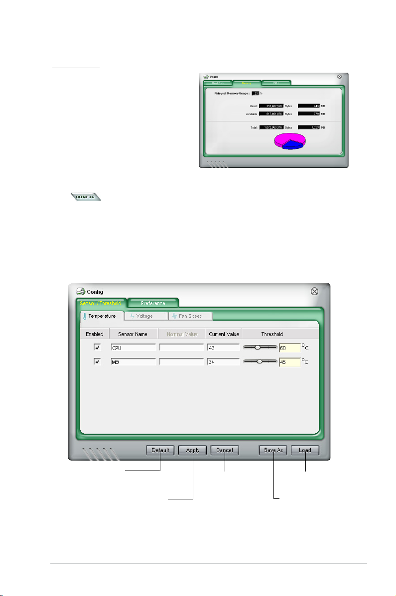
Memory usage
The Memory tab shows both used
and available physical memory. The
pie chart at the bottom of the window
represents the used (blue) and the
available physical memory.
ConguringPCProbeII
Click to view and adjust the sensor threshold values.
The Cong window has two tabs: Sensor/Threshold and Preference. The
Sensor/Threshold tab enables you to activate the sensors or to adjust the sensor
threshold values. The Preference tab allows you to customize sensor alerts,
change temperature scale, or enable the Q-Fan feature.
Loads the default
threshold values for
each sensor
Applies your
changes
Cancels or
ignores your
changes
Loads your saved
conguration
Saves your
conguration
3-17ASUS V-Series P5P43
Page 64

3-18 Chapter 3: Starting up
Page 65
Chapter 4
R
R
This chapter gives information about
he motherboard that comes with the
system. This chapter includes the
motherboard layout, jumper settings,
and connector locations.
Motherboard introduction
Page 66

4.1 Introduction
P5QL-M DELUXE/WIFI-AP
PCIEX16
PCIEX1_1
PCI2
PCI1
PRI_IDE
FLOPPY
USB910 USB78
IE1394_2
PANEL
AAFP
CD
ATX12V
EATXPWR
CPU_FAN
COM1
PWR_FAN
CHA_FAN
Intel
®
P43
Super
I/O
AUDIO
VIA
VT1708S
RTL
8111C
RTL
8111C
RTM870T-954
KB_USB56
SB_PWR
CLRTC
CHASSIS
24.4cm(9.6in)
24.4cm(9.6in)
LGA775
Intel
®
ICH10R
DDR2 DIMM_A1 (64bit, 240-pin module)
DDR2 DIMM_B1 (64bit, 240-pin module)
LAN1_USB12
LAN2_USB34
F_ESATA12
8Mb
BIOS
JMB381
JMB363
Lithium Cell
CMOS Power
SPDIF_OUT
SPDIF_O12
SATA2
SATA1
SATA4
SATA3
SATA6
SATA5
The Vintage V-Series P5P43 barebone system comes with an ASUS motherboard.
This chapter provides technical information about the motherboard for future
upgrades or system reconguration.
4.2 Motherboard layout
4-2 Chapter 4: Motherboard info
Page 67
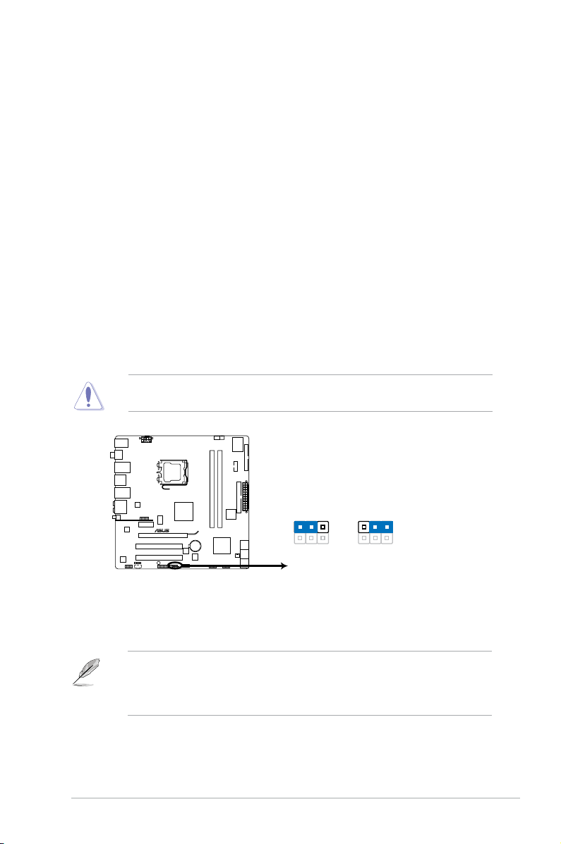
4.3 Jumpers
P5QL-M DELUXE/WIFI-AP
P5QL-M DELUXE/WIFI-AP Clear RTC RAM
1 2 2 3
Normal
(Default)
Clear RTC
CLRTC
1. Clear RTC RAM (CLRTC)
This jumper allows you to clear the Real Time Clock (RTC) RAM in
CMOS. You can clear the CMOS memory of date, time, and system setup
parameters by erasing the CMOS RTC RAM data. The onboard button
cell battery powers the RAM data in CMOS, which include system setup
information such as system passwords.
To erase the RTC RAM:
1. Turn OFF the computer and unplug the power cord.
2. Remove the onboard battery.
3. Move the jumper cap from pins 1-2 (default) to pins 2-3. Keep the cap on pins
2-3 for about 5~10 seconds, then move the cap back to pins 1-2.
4. Re-install the battery.
5. Plug the power cord and turn ON the computer.
6. Hold down the <Del> key during the boot process and enter BIOS setup to
re-enter data.
Except when clearing the RTC RAM, never remove the cap on CLRTC jumper
default position. Removing the cap will cause system boot failure!
You do not need to clear the RTC when the system hangs due to overclocking.
For system failure due to overclocking, use the C.P.R. (CPU Parameter Recall)
feature. Shut down and reboot the system so the BIOS can automatically reset
parameter settings to default values.
4-3ASUS V-Series P5P43
Page 68

4.3 Connectors
P5QL-M DELUXE/WIFI-AP
P5QL-M DELUXE/WIFI-AP Floppy disk drive connector
FLOPPY
NOTE:Orient the red markings
on the floppy ribbon cable to PIN 1.
PIN1
1. Floppy disk drive connector (34-1 pin FLOPPY)
This connector is for the provided oppy disk drive (FDD) signal cable. Insert
one end of the cable to this connector, then connect the other end to the
signal connector at the back of the oppy disk drive.
Pin 5 on the connector is removed to prevent incorrect cable connection when
using an FDD cable with a covered Pin 5.
4-4 Chapter 4: Motherboard info
Page 69

2. IDE connector (40-1 pin PRI_IDE)
P5QL-M DELUXE/WIFI-AP
PRI_IDE
NOTE:Orient the red markings
on the IDE ribbon cable to PIN 1.
PIN1
P5QL-M DELUXE/WIFI-AP IDE connector
The onboard IDE connector is for Ultra DMA 133 / 100 / 66 / 33 signal cable.
There are three connectors on each Ultra DMA 100/66/33 signal cable:
blue, black, and gray. Connect the blue connector to the motherboard’s IDE
connector, then select one of the following modes to congure your device(s).
Drive jumper setting Mode of
Single device Cable-Select or Master - Black
Two devices Cable-Select Master
• Pin 20 on the IDE connector is removed to match the covered hole on the
Ultra DMA cable connector. This prevents incorrect insertion when you
connect the IDE cable.
• Use the 80-conductor IDE cable for Ultra DMA 133 / 100 / 66 / 33 IDE
devices.
If any device jumper is set as “Cable-Select,” ensure that all other device
jumpers have the same setting.
device(s)
Cable connector
Black
Slave Gray
Master Master Black or gray
Slave Slave
4-5ASUS V-Series P5P43
Page 70

3. ICH10R Serial ATA connectors
SATA5
GND
RSATA_RXN5
RSATA_RXP5
GND
RSATA_TXN5
RSATA_TXP5
GND
SATA6
GND
RSATA_RXN6
RSATA_RXP6
GND
RSATA_TXN6
RSATA_TXP6
GND
SATA3
GND
RSATA_RXN3
RSATA_RXP3
GND
RSATA_TXN3
RSATA_TXP3
GND
SATA4
GND
RSATA_RXN4
RSATA_RXP4
GND
RSATA_TXN4
RSATA_TXP4
GND
SATA1
GND
RSATA_RXN1
RSATA_RXP1
GND
RSATA_TXN1
RSATA_TXP1
GND
SATA2
GND
RSATA_RXN2
RSATA_RXP2
GND
RSATA_TXN2
RSATA_TXP2
GND
P5QL-M DELUXE/WIFI-AP
P5QL-M DELUXE/WIFI-AP SATA connectors(ICH10R®)
CD
Left Audio Channel
GND
GND
Right Audio Channel
P5QL-M DELUXE/WIFI-AP
P5QL-M DELUXE/WIFI-AP Internal audio connector
(7-pin SATA1, SATA2, SATA3, SATA4, SATA 5, SATA 6)
These connectors are for the Serial ATA signal cables for Serial ATA hard disk
drives.
Connect the right-angle side
right angle side
of SATA signal cable to SATA
device. Or you may connect the
right-angle side of SATA cable to
the onboard SATA port to avoid
mechanical conict with huge
graphics cards.
4. Optical drive audio connector (4-pin CD)
These connectors allow you to receive stereo audio input from sound sources
such as a CD-ROM, TV tuner, or MPEG card.
4-6 Chapter 4: Motherboard info
Page 71

5. Digital audio connector (4-1 pin SPDIF_OUT for ASUS HDMI VGA card)
SPDIF_OUT
+5V
SPDIFOUT
GND
P5QL-M DELUXE/WIFI-AP
P5QL-M DELUXE/WIFI-AP Digital audio connector
P5QL-M DELUXE/WIFI-AP
P5QL-M DELUXE/WIFI-AP USB2.0 connectors
PIN 1
USB+5V
USB_P8-
USB_P8+
GND
NC
USB+5V
USB_P7-
USB_P7+
GND
USB78
PIN 1
USB+5V
USB_P10-
USB_P10+
GND
NC
USB+5V
USB_P9-
USB_P9+
GND
USB910
This connector is for an additional Sony/Philips Digital Interface (S/PDIF)
port(s). If you are using an ASUS HDMI-equipped graphics card, connect the
HDMI card to this connector with a S/PDIF Out cable.
The ASUS HDMI-equipped graphics card and the S/PDIF Out cable are
purchased separately.
6. USB connectors (10-1 pin USB78, USB 910, USB1112)
These connectors are for USB 2.0 ports. Connect the USB module cable
to any of these connectors, then install the module to a slot opening at the
back of the system chassis. These USB connectors comply with USB 2.0
specication that supports up to 480 Mbps connection speed.
Never connect a 1394 cable to the USB connectors. Doing so will damage the
motherboard!
You can connect the front panel USB cable to the ASUS Q-Connector (USB,
blue) rst, and then install the Q-Connector (USB) to the USB connector
onboard if your chassis supports front panel USB ports.
The USB module cable is purchased separately.
4-7ASUS V-Series P5P43
Page 72
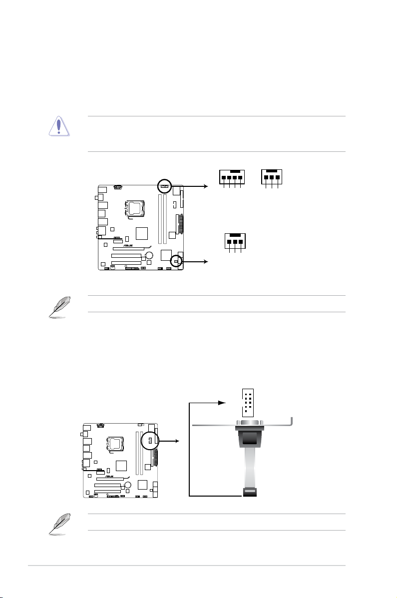
7. CPU, chassis, and power fan connectors
P5QL-M DELUXE/WIFI-AP
P5QL-M DELUXE/WIFI-AP fan connectors
PWR_FAN
Rotation
+12V
GND
Rotation
+12V
GND
CHA_FAN
CPU_FAN
CPU FAN PWM
CPU FAN IN
CPU FAN PWR
GND
P5QL-M DELUXE/WIFI-AP
P5QL-M DELUXE/WIFI-AP Serial port (COM1) connector
PIN 1
COM1
(4-pin CPU_FAN, 3-pin CHA_FAN1, 3-pin PWR_FAN)
The fan connectors support cooling fans of 350 mA~2000 mA (24 W max.)
or a total of 1 A~7 A (84 W max.) at +12V. Connect the fan cables to the fan
connectors on the motherboard, making sure that the black wire of each
cable matches the ground pin of the connector.
Do not forget to connect the fan cables to the fan connectors. Insufcient air
ow inside the system may damage the motherboard components. These are
not jumpers! Do not place jumper caps on the fan connectors!
Only the CPU-FAN connectors support the ASUS Q-FAN feature.
8. Serial port connector (10-1 pin COM1)
This connector is for a serial (COM) port. Connect the serial port module
cable to this connector, then install the module to a slot opening at the back
of the system chassis.
The serial port module is purchased separately.
4-8 Chapter 4: Motherboard info
Page 73

9. Chassis intrusion connector (4-1 pin CHASSIS)
P5QL-M DELUXE/WIFI-AP
+5VSB_MB
Chassis Signal
GND
CHASSIS
P5QL-M DELUXE/WIFI-AP Chassis intrusion connecto
r
P5QL-M DELUXE/WIFI-AP
P5QL-M DELUXE/WIFI-AP Analog front panel connecto
r
AAFP
PIN 1
GND
PRESENCE#
SENSE1_RETUR
SENSE2_RETUR
PORT1 L
PORT1 R
PORT2 R
SENSE_SEND
PORT1 L
HD-audio-compliant
pin definition
PIN 1
AGNDNCNC
NC
MIC2
MICPWR
Line out_R
NC
Line out_L
Legacy AC’97
compliant definition
This connector is for a chassis-mounted intrusion detection sensor or switch.
Connect one end of the chassis intrusion sensor or switch cable to this
connector. The chassis intrusion sensor or switch sends a high-level signal to
this connector when a chassis component is removed or replaced. The signal
is then generated as a chassis intrusion event.
By default, the pin labeled “Chassis Signal” and “Ground” are shorted with
a jumper cap. Remove the jumper caps only when you intend to use the
chassis intrusion detection feature.
10. Front panel audio connector (10-1 pin AAFP)
This connector is for a chassis-mounted front panel audio I/O module that
supports either HD Audio or legacy AC`97 audio standard. Connect one end
of the front panel audio I/O module cable to this connector.
•
We recommend that you connect a high-denition front panel audio module
to this connector to avail of the motherboard’s high-denition audio capability.
•
If you want to connect a high-denition front panel audio module to this
connector, set the Front Panel Type item in the BIOS setup to [HD Audio];
if you want to connect an AC'97 front panel audio module to this connector,
set the item to [AC'97]. By default, this connector is set to [HD Audio]. See
section 5.4.5OnboardDevicesConguration for details.
4-9ASUS V-Series P5P43
Page 74
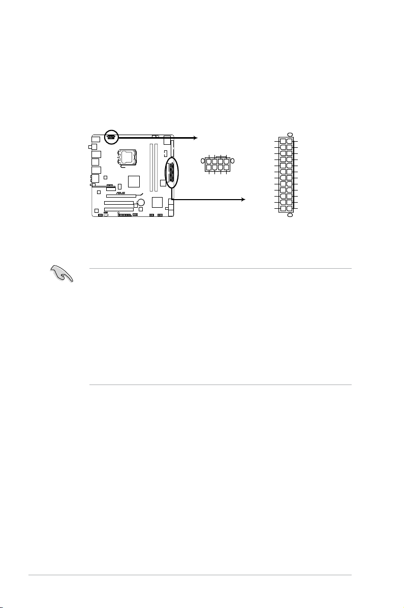
11. ATX power connectors (24-pin EATXPWR, 4-pin ATX12V)
P5QL-M DELUXE/WIFI-AP
P5QL-M DELUXE/WIFI-AP ATX power connectors
EATXPWR
PIN 1
GND
+5 Volts
+5 Volts
+5 Volts
-5 Volts
GND
GND
GND
PSON#
GND
-12 Volts
+3 Volts
+3 Volts
+12 Volts
+12 Volts
+5V Standby
Power OK
GND
+5 Volts
GND
+5 Volts
GND
+3 Volts
+3 Volts
EATX12V
PIN 1
+12V DC
+12V DC
+12V DC
+12V DC
GND
GND
GND
GND
These connectors are for ATX power supply plugs. The power supply plugs
are designed to t these connectors in only one orientation. Find the proper
orientation and push down rmly until the connectors completely t.
•
For a fully congured system, we recommend that you use a power supply
unit (PSU) that complies with ATX 12 V Specication 2.0 (or later version)
and provides a minimum power of 400 W.
• Do not forget to connect the 4-pin EATX12V power plug; otherwise, the
system will not boot.
• Use of a PSU with a higher power output is recommended when
conguring a system with more power-consuming devices. The system
may become unstable or may not boot up if the power is inadequate.
• If you want to use PCI Express x16 card, use a PSU with 500W to 600W
power or above to ensure the system stability.
4-10 Chapter 4: Motherboard info
Page 75
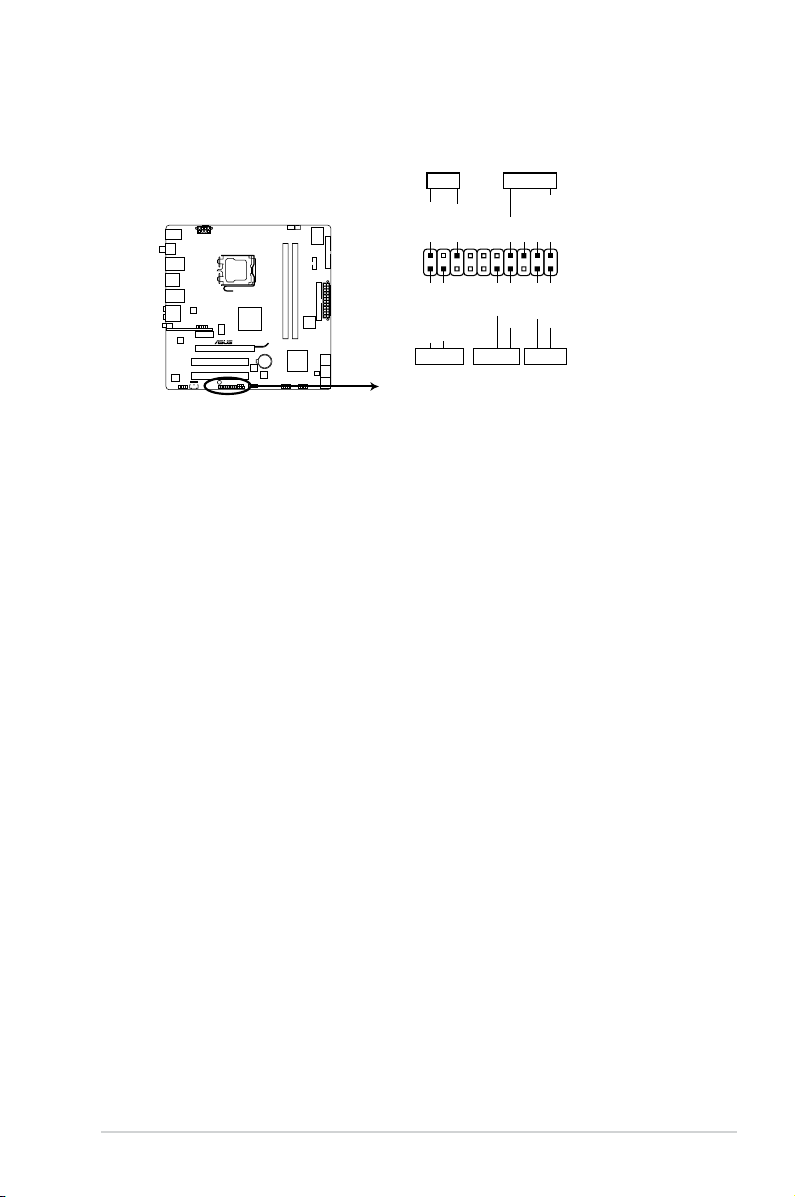
12. System panel connector (20-8 pin F_PANEL)
P5QL-M DELUXE/WIFI-AP
P5QL-M DELUXE/WIFI-AP System panel connector
PIN 1
* Requires an ATX power supply
PLED SPEAKER
PLED+
PLED-
+5V
Ground
Ground
Speaker
IDE_LED+
IDE_LED-
PWR
Ground
Reset
Ground
PANEL
IDE_LED PWRSW RESET
This connector supports several chassis-mounted functions.
•
System power LED (2-pin PLED)
This 2-pin connector is for the system power LED. Connect the chassis
power LED cable to this connector. The system power LED lights up when
you turn on the system power, and blinks when the system is in sleep mode.
•
Hard disk drive activity LED (2-pin IDE_LED)
This 2-pin connector is for the HDD Activity LED. Connect the HDD Activity
LED cable to this connector. The IDE LED lights up or ashes when data is
read from or written to the HDD.
•
System warning speaker (4-pin SPEAKER)
This 4-pin connector is for the chassis-mounted system warning speaker. The
speaker allows you to hear system beeps and warnings.
•
ATX power button/soft-off button (2-pin PWRSW)
This connector is for the system power button. Pressing the power button
turns the system on or puts the system in sleep or soft-off mode depending
on the BIOS settings. Pressing the power switch for more than four seconds
while the system is ON turns the system OFF.
•
Reset button (2-pin RESET)
This 2-pin connector is for the chassis-mounted reset button for system
reboot without turning off the system power.
4-11ASUS V-Series P5P43
Page 76

4-12 Chapter 4: Motherboard info
Page 77
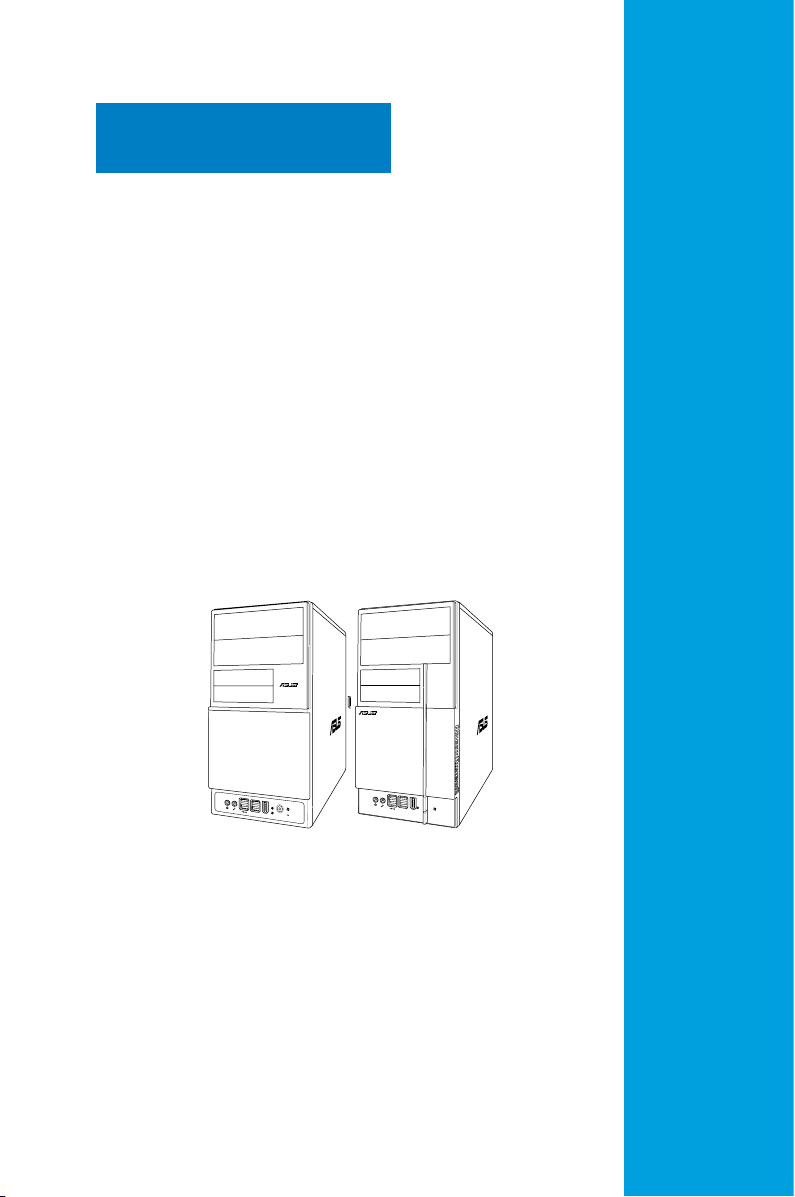
Chapter 5
R
R
This chapter tells how to change
system settings through the BIOS
Setup menus and describes the BIOS
parameters.
BIOS setup
Page 78

5.1 Managing and updating your BIOS
The following utilities allow you to manage and update the motherboard Basic
Input/Output System (BIOS) setup.
1. ASUS Update
2. ASUS EZ Flash 2
3. ASUS AFUDOS
4. ASUS CrashFree BIOS 3
USB ash disk or the motherboard support DVD when the BIOS le fails or
gets corrupted.)
Refer to the corresponding sections for details on these utilities.
Save a copy of the original motherboard BIOS le to a bootable oppy disk or
USB ash disk in case you need to restore the BIOS in the future. Copy the
original motherboard BIOS using the ASUS Update or AFUDOS utilities.
(Updates the BIOS in Windows® environment.)
(Updates the BIOS using a oppy disk or USB ash disk.)
(Updates the BIOS using a bootable oppy disk.)
(Updates the BIOS using a bootable oppy disk,
5.1.1 ASUS Update utility
The ASUS Update is a utility that allows you to manage, save, and update the
motherboard BIOS in Windows® environment. The ASUS Update utility allows you
to:
• Save the current BIOS le
• Download the latest BIOS le from the Internet
• Update the BIOS from an updated BIOS le
• Update the BIOS directly from the Internet, and
• View the BIOS version information.
This utility is available in the support DVD that comes with the motherboard
package.
ASUS Update requires an Internet connection either through a network or an
Internet Service Provider (ISP).
Installing ASUS Update
To install ASUS Update:
1. Place the support DVD in the optical drive. The Drivers menu appears.
2. Click the
3. The ASUS Update utility is copied to your system.
5-2 Chapter 5: BIOS setup
Utilities tab, then click Install ASUS Update.
Page 79
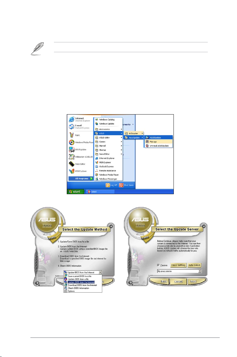
Quit all Windows® applications before you update the BIOS using this utility.
Updating the BIOS through the Internet
To update the BIOS through the Internet:
1. Launch the ASUS Update utility from the Windows
> Programs > ASUS > ASUSUpdate > ASUSUpdate. The ASUS Update
main window appears.
®
desktop by clicking Start
2. Select Update BIOS from the
Internet option from the drop-down
menu, then click Next.
ASUS V-Series P5P43 5-3
3. Select the ASUS FTP site nearest
you to avoid network trafc, or
click Auto Select. Click Next.
Page 80

4. From the FTP site, select the BIOS
version that you wish to download.
Click Next.
5. Follow the screen instructions to
complete the update process.
The ASUS Update utility is
capable of updating itself through
the Internet. Always update the
utility to avail all its features.
UpdatingtheBIOSthroughaBIOSle
To update the BIOS through a BIOS le:
1. Launch the ASUS Update utility from the Windows
> Programs > ASUS > ASUSUpdate > ASUSUpdate. The ASUS Update
main window appears.
2. Select Update BIOS from a le
option from the drop-down menu,
then click Next.
®
desktop by clicking Start
3. Locate the BIOS le from the Open
window, then click Open.
4. Follow the screen instructions to
P5QL-M.rom
complete the update process.
P5QL-M
5-4 Chapter 5: BIOS setup
Page 81

5.1.2 Creatingabootableoppydisk
1. Do either one of the following to create a bootable oppy disk.
DOS environment
a. Insert a 1.44MB oppy disk into the drive.
format
b. At the DOS prompt, type
Windows® XP environment
a. Insert a 1.44 MB oppy disk to the oppy disk drive.
b. Click
Start from the Windows® desktop, then select My Computer.
c. Select the 3 1/2 Floppy Drive icon.
d. Click File from the menu, then select
Disk window appears.
e. Select Create an MS-DOS startup disk
then click Start.
Windows® Vista environment
a. Insert a formatted, high density 1.44 MB oppy disk to the oppy disk
drive.
A:/S then press <Enter>.
Format. A Format 3 1/2 Floppy
from the format options eld,
b. Click
c. Right-click Floppy Disk Drive then click
from the Windows® desktop, then select Computer.
Format to display the
Format 3 1/2 Floppy dialog box.
d. Select the Create an MS-DOS startup disk
e. Click
Start.
check box.
2. Copy the original or the latest motherboard BIOS le to the bootable oppy
disk.
ASUS V-Series P5P43 5-5
Page 82

5.1.3 ASUS EZ Flash 2 utility
The ASUS EZ Flash 2 feature allows you to update the BIOS without having to go
through the long process of booting from a oppy disk and using a DOS-based
utility. The EZ Flash 2 utility is built-in the BIOS chip so it is accessible by pressing
<Alt> + <F2> during the Power-On Self Tests (POST).
To update the BIOS using EZ Flash 2:
1. Visit the ASUS website (www.asus.com) to download the latest BIOS le for
the motherboard.
2. Save the BIOS le to a oppy disk or a USB ash disk, then restart the
system.
3. You can launch the EZ Flash 2 by two methods.
Insert the oppy disk / USB ash disk that contains the BIOS le to the
(1)
oppy disk drive or the USB port.
Press <Alt> + <F2> during POST to display the following.
ASUSTek EZ Flash 2 BIOS ROM Utility V3.25
FLASH TYPE: MXIC 25L8005
Current ROM
BOARD: P5QL-M V-P5P43
VER: 0205 (H:00 B:03)
DATE: 09/01/08
PATH: C:\
A:
C:
Update ROM
BOARD: Unknown
VER: Unknown
DATE: Unknown
Note
[Enter] Select or Load [B] Backup [ESC] Exit
[Tab] Switch [Up/Down/Home/End] Move
(2) Enter BIOS setup program. Go to the
Tools menu to select EZ Flash2
and press <Enter> to enable it.
You can switch between drives by pressing <Tab> before the correct le
is found. Then press <Enter>.
4. When the correct BIOS le is found, EZ Flash 2 performs the BIOS update
process and automatically reboots the system when done.
• This function can support devices such as USB ash disk, or oppy disk
with
FAT 32/16
• Do not shut down or reset the system while updating the BIOS to prevent
system boot failure!
5-6 Chapter 5: BIOS setup
format and single partition only.
Page 83

5.1.4 AFUDOS utility
The AFUDOS utility allows you to update the BIOS le in DOS environment using
a bootable oppy disk with the updated BIOS le. This utility also allows you to
copy the current BIOS le that you can use as backup when the BIOS fails or gets
corrupted during the updating process.
Copying the current BIOS
To copy the current BIOS le using the AFUDOS utility:
• Make sure that the oppy disk is not write-protected and has at least
1024KB free space to save the le.
• The succeeding BIOS screens are for reference only. The actual BIOS
screen displays may not be same as shown.
1. Copy the AFUDOS utility (afudos.exe) from the motherboard support DVD to
the bootable oppy disk you created earlier.
2. Boot the system in DOS mode, then at the prompt type:
afudos /o[lename]
where the [lename] is any user-assigned lename not more than eight
alphanumeric characters for the main lename and three alphanumeric
characters for the extension name.
A:\>afudos /oOLDBIOS1.rom
Mainlename Extension name
3. Press <Enter>. The utility copies the current BIOS le to the oppy disk.
A:\>afudos /oOLDBIOS1.rom
AMI Firmware Update Utility - Version 1.19(ASUS V2.07(03.11.24BB))
Copyright (C) 2002 American Megatrends, Inc. All rights reserved.
Reading ash ..... done
Write to le...... ok
A:\>
The utility returns to the DOS prompt after copying the current BIOS le.
UpdatingtheBIOSle
To update the BIOS le using the AFUDOS utility:
1. Visit the ASUS website (www.asus.com) and download the latest BIOS le for
the motherboard. Save the BIOS le to a bootable oppy disk.
ASUS V-Series P5P43 5-7
Page 84

Write the BIOS lename on a piece of paper. You need to type the exact BIOS
lename at the DOS prompt.
2. Copy the AFUDOS utility (afudos.exe) from the motherboard support DVD to
the bootable oppy disk you created earlier.
3. Boot the system in DOS mode, then at the prompt type:
afudos /i[lename]
where [lename] is the latest or the original BIOS le on the bootable oppy
disk.
A:\>afudos /iP5QLM.ROM
4. The utility veries the le and starts updating the BIOS.
A:\>afudos /iP5QLM.ROM
AMI Firmware Update Utility - Version 1.19(ASUS V2.07(03.11.24BB))
Copyright (C) 2002 American Megatrends, Inc. All rights reserved.
WARNING!! Do not turn off power during ash BIOS
Reading le ....... done
Reading ash ...... done
Advance Check ......
Erasing ash ...... done
Writing ash ...... 0x0008CC00 (9%)
Do not shut down or reset the system while updating the BIOS to prevent
system boot failure!
5. The utility returns to the DOS prompt after the BIOS update process is
completed. Reboot the system from the hard disk drive.
A:\>afudos /iP5QLM.ROM
AMI Firmware Update Utility - Version 1.19(ASUS V2.07(03.11.24BB))
Copyright (C) 2002 American Megatrends, Inc. All rights reserved.
WARNING!! Do not turn off power during ash BIOS
Reading le ....... done
Reading ash ...... done
Advance Check ......
Erasing ash ...... done
Writing ash ...... done
Verifying ash .... done
Please restart your computer
A:\>
5-8 Chapter 5: BIOS setup
Page 85

5.1.5 ASUS CrashFree BIOS 3 utility
The ASUS CrashFree BIOS 3 is an auto recovery tool that allows you to restore
the BIOS le when it fails or gets corrupted during the updating process. You can
update a corrupted BIOS le using the motherboard support DVD, the oppy disk,
or the USB ash disk that contains the updated BIOS le.
• Prepare the motherboard support DVD, the oppy disk or the USB ash
disk containing the updated motherboard BIOS before using this utility.
• If you use a SATA optical drive, always connect the SATA cable to the
SATA1/SATA2 connector; otherwise, the utility will not function.
Recovering the BIOS from the support DVD
To recover the BIOS from the support DVD:
1. Turn on the system.
2. Insert the motherboard support DVD to the optical drive.
3. The utility displays the following message and automatically checks the DVD
for the BIOS le.
Bad BIOS checksum. Starting BIOS recovery...
Checking for oppy...
When found, the utility reads the BIOS le and starts ashing the corrupted
BIOS le.
Bad BIOS checksum. Starting BIOS recovery...
Checking cd-rom...
Optical drive found!
Reading le “P5QLM.ROM”. Completed.
Start ashing...
4. Restart the system after the utility completes the updating process.
RecoveringtheBIOSfromtheUSBashdisk
To recover the BIOS from the USB ash disk:
1. Insert the USB ash disk that contains BIOS le to the USB port.
2. Turn on the system.
3. The utility will automatically checks the devices for the BIOS le When found,
the utility reads the BIOS le and starts ashing the corrupted BIOS le.
4. Restart the system after the utility completes the updating process.
• Only the USB ash disk with FAT 32/16 format and single partition can
support ASUS CrashFree BIOS 3. The device size should be smaller than
8GB.
• DO NOT shut down or reset the system while updating the BIOS! Doing so
can cause system boot failure!
ASUS V-Series P5P43 5-9
Page 86

5.2 BIOS setup program
This motherboard supports a programmable Serial Peripheral Interface (SPI) chip
that you can update using the provided utility described in section “4.1 Managing
and updating your BIOS.”
Use the BIOS Setup program when you are installing a motherboard, reconguring
your system, or prompted to “Run Setup.” This section explains how to congure
your system using this utility.
Even if you are not prompted to use the Setup program, you can change the
conguration of your computer in the future. For example, you can enable the
security password feature or change the power management settings. This
requires you to recongure your system using the BIOS Setup program so that the
computer can recognize these changes and record them in the CMOS RAM of the
SPI chip.
The SPI chip on the motherboard stores the Setup utility. When you start up the
computer, the system provides you with the opportunity to run this program. Press
<Del> during the Power-On Self-Test (POST) to enter the Setup utility; otherwise,
POST continues with its test routines.
If you wish to enter Setup after POST, restart the system by pressing
<Ctrl+Alt+Delete>, or by pressing the reset button on the system chassis. You can
also restart by turning the system off and then back on. Do this last option only if
the rst two failed.
The Setup program is designed to make it as easy to use as possible. Being a
menu-driven program, it lets you scroll through the various sub-menus and make
your selections from the available options using the navigation keys.
• The default BIOS settings for this motherboard apply for most conditions
to ensure optimum performance. If the system becomes unstable after
changing any BIOS settings, load the default settings to ensure system
compatibility and stability. Select the Load Setups Default item under the
Exit Menu. See section 5.8 Exit Menu.
• The BIOS setup screens shown in this section are for reference purposes
only, and may not exactly match what you see on your screen.
• Visit the ASUS website (www.asus.com) to download the latest BIOS le for
this motherboard.
5-10 Chapter 5: BIOS setup
Page 87

5.2.1 BIOS menu screen
Menu items
Menu bar
Congurationelds
General help
Main Advanced Power Boot Tools Exit
System Time [19:34:30]
System Date [Mon 05/12/2008]
Legacy Diskette A [1.44M, 3.5 in.]
SATA 1 :[Not Detected]
SATA 2 :[Not Detected]
SATA 3 :[Not Detected]
SATA 4 :[Not Detected]
SATA 5 :[Not Detected]
SATA 6 :[Not Detected]
Storage Conguration
System Information
v02.58 (C)Copyright 1985-2008, American Megatrends, Inc.
Sub-menu items
BIOS SETUP UTILITY
Use [ENTER], [TAB]
or [SHIFT-TAB] to
select a eld.
Use [+] or [-] to
congure system
Time.
Select Screen
Select Item
Change Field
+-
Tab Select Field
F1 General Help
F10 Save and Exit
ESC Exit
Navigation keys
5.2.2 Menu bar
The menu bar on top of the screen has the following main items:
Main For changing the basic system conguration
Advanced For changing the advanced system settings
Power For changing the advanced power management (APM)
conguration
Boot For changing the system boot conguration
Tools For Conguring options for special functions
Exit For selecting the exit options and loading default settings.
To select an item on the menu bar, press the right or left arrow key on the keyboard
until the desired item is highlighted.
5.2.3 Navigation keys
At the bottom right corner of a menu screen are the navigation keys for that
particular menu. Use the navigation keys to select items in the menu and change
the settings.
Some of the navigation keys differ from one screen to another.
ASUS V-Series P5P43 5-11
Page 88

5.2.4 Menu items
The highlighted item on the menu bar
displays the specic items for that
menu. For example, selecting Main
shows the Main menu items.
The other items (Advanced, Power,
Boot, and Exit) on the menu bar have
their respective menu items.
System Time [06:22:54]
System Date [Fri 03/09/2007]
Legacy Diskette A [1.44M, 3.5 in]
SATA 1 [Not Detected]
SATA 2 [Not Detected]
SATA 3 [Not Detected]
SATA 4 [Not Detected]
SATA 5 [Not Detected]
SATA 6 [Not Detected]
Storage Conguration
System Information
Main menu items
Use [ENTER], [TAB],
or [SHIFT-TAB] to
select a eld.
Use [+] or [-] to
congure system
Time.
5.2.5 Sub-menu items
A solid triangle before each item on any menu screen means that the iteam has a
sub-menu. To display the sub-menu, select the item and press <Enter>.
5.2.6 Congurationelds
These elds show the values for the menu items. If an item is user- congurable,
you can change the value of the eld opposite the item. You cannot select an item
that is not user-congurable.
A congurable eld is enclosed in brackets, and is highlighted when selected. To
change the value of a eld, select it then press <Enter> to display a list of options.
Refer to “4.2.7 Pop-up window.”
5.2.7 Pop-up window
Select a menu item then press <Enter> to display a pop-up window with the
conguration options for that item.
5.2.8 Scroll bar
A scroll bar appears on the right side of a
menu screen when there are items that do
not t on the screen. Press the
Up/Down arrow keys or <Page Up> /<Page
Down> keys to display the other items on
the screen.
5.2.9 General help
At the top right corner of the menu screen
is a brief description of the selected item.
5-12 Chapter 5: BIOS setup
Pop-up window
Scroll bar
Page 89

5.3 Main menu
When you enter the BIOS Setup program, the Main menu screen appears, giving
you an overview of the basic system information.
Refer to section 2.2.1 BIOS menu screen for information on the menu screen
items and how to navigate through them.
Main Advanced Power Boot Tools Exit
System Time [19:34:30]
System Date [Mon 05/12/2008]
Legacy Diskette A [1.44M, 3.5 in.]
SATA 1 :[Not Detected]
SATA 2 :[Not Detected]
SATA 3 :[Not Detected]
SATA 4 :[Not Detected]
SATA 5 :[Not Detected]
SATA 6 :[Not Detected]
Storage Conguration
System Information
v02.58 (C)Copyright 1985-2008, American Megatrends, Inc.
BIOS SETUP UTILITY
Use [ENTER], [TAB]
or [SHIFT-TAB] to
select a eld.
Use [+] or [-] to
congure system
Time.
Select Screen
Select Item
Change Field
+-
Tab Select Field
F1 General Help
F10 Save and Exit
ESC Exit
5.3.1 System Time [xx:xx:xx]
Allows you to set the system time.
5.3.2 System Date [Day xx/xx/xxxx]
Allows you to set the system date.
5.3.3 Legacy Diskette A [1.44M, 3.5 in.]
Sets the type of oppy drive installed.
Conguration options: [Disabled] [360k, 5.25 in.] [1.2M, 5.25 in.] [720K, 3.5 in.]
[1.44M, 3.5 in.] [2.88M, 3.5 in.]
ASUS V-Series P5P43 5-13
Page 90
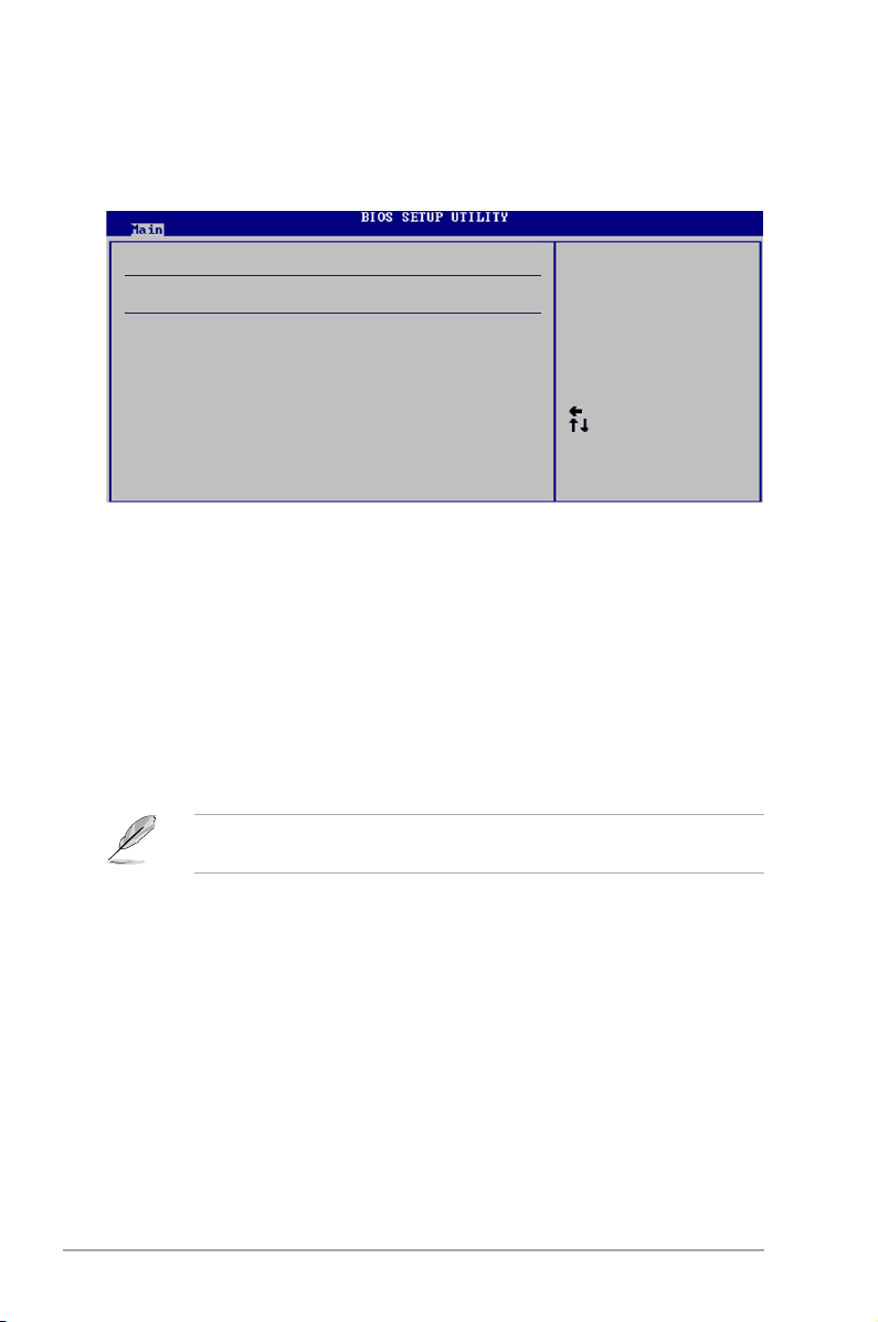
5.3.4 SATA 1~6
Select Screen
Select Item
+- Change Option
F1 General Help
F10 Save and Exit
ESC Exit
While entering Setup, the BIOS automatically detects the presence of IDE devices.
There is a separate sub-menu for each IDE device. Select a device item then
press <Enter> to display the IDE device information.
SATA 1
Device : Not Detected
Type [Auto]
LBA/Large Mode [Auto]
Block(Multi-Sector Transfer) M [Auto]
PIO Mode [Auto]
DMA Mode [Auto]
SMART Monitoring [Auto]
32Bit Data Transfer [Enabled]
Select the type of
device connected to the
system.
The BIOS automatically detects the values opposite the dimmed items (Device,
Vendor, Size, LBA Mode, Block Mode, PIO Mode, Async DMA, Ultra DMA, and
SMART monitoring). These values are not user-congurable. These items show
N/A if no IDE device is installed in the system.
Type [Auto]
Selects the type of IDE drive. Setting to [Auto] allows automatic selection of the
appropriate IDE device type. Select [CDROM] if you are specically conguring a
CD-ROM drive. Select [ARMD] (ATAPI Removable Media Device) if your device is
either a ZIP, LS-120, or MO drive.
Conguration options: [Not Installed] [Auto] [CDROM] [ARMD]
This item does not appear when you select the PATA Primary Master/Slave
device.
LBA/Large Mode [Auto]
Enables or disables the LBA mode. Setting to [Auto] enables the LBA mode if the
device supports this mode, and if the device was not previously formatted with LBA
mode disabled. Conguration options: [Disabled] [Auto]
Block (Multi-sector Transfer) [Auto]
Enables or disables data multi-sectors transfers. When set to [Auto], the data
transfer from and to the device occurs multiple sectors at a time if the device
supports multi-sector transfer feature. When set to [Disabled], the data transfer
from and to the device occurs one sector at a time.
Conguration options: [Disabled] [Auto]
5-14 Chapter 5: BIOS setup
Page 91
PIO Mode [Auto]
Selects the PIO mode.
Conguration options: [Auto] [0] [1] [2] [3] [4]
DMA Mode [Auto]
Selects the DMA mode. Conguration options: [Auto] [SWDMA0] [SWDMA1]
[SWDMA2] [MWDMA0] [MWDMA1] [MWDMA2] [UDMA0] [UDMA1] [UDMA2]
[UDMA3] [UDMA4] [UDMA5]
SMART Monitoring [Auto]
Sets the Smart Monitoring, Analysis, and Reporting Technology.
Conguration options: [Auto] [Disabled] [Enabled]
32Bit Data Transfer [Enabled]
Enables or disables 32-bit data transfer.
Conguration options: [Disabled] [Enabled]
5.3.5 StorageConguration
The items in this menu allow you to set or change the congurations for the SATA
devices installed in the system. Select an item then press <Enter> if you want to
congure the item.
SATA Conguration
SATA Conguration [Enhanced]
Congure SATA as [IDE]
Hard Disk Write Protect [Disabled]
IDE Detect Time Out (Sec) [35]
Options
Disabled
Compatiable
Enhanced
SATAConguration[Enhanced]
Conguration options: [Disabled] [Compatible] [Enhanced]
CongureSATAAs[IDE]
Sets the conguration for the Serial ATA connectors supported by the Southbridge
chip.
The AHCI allows the onboard storage driver to enable advanced Serial ATA
features that increases storage performance on random workloads by allowing the
drive to internally optimize the order of commands.
If you want to use the Serial ATA hard disk drives as Parallel ATA physical storage
devices, keep the defaul setting [IDE].
If you want the Serial ATA hard disk drives to use the Advanced Host Controller
Interface (AHCI), set this item to [AHCI].
ASUS V-Series P5P43 5-15
Page 92

Hard Disk Write Protect [Disabled]
Disables or enables device write protection. This will be effective only if device is
accessed throuh BIOS. Conuration option: [Disabled] [Enabled]
SATA Detect Time Out (Sec) [35]
Selects the time out value for detecting ATA/ATAPI devices.
Conguration options: [0] [5] [10] [15] [20] [25] [30] [35]
5.3.6 System Information
This menu gives you an overview of the general system specications. The BIOS
automatically detects the items in this menu.
AMIBIOS
Version : 0202
Build Date : 09/01/08
Processor
Type : Intel(R) Core(TM)2 CPU 6300 @ 1.86GHz
Speed : 1866MHz
Count : 2
System Memory
Installed Size: 512MB
Usable Size: 478MB
AMI BIOS
Displays the auto-detected BIOS information.
Processor
Displays the auto-detected CPU specication.
System Memory
Displays the auto-detected system memory.
5-16 Chapter 5: BIOS setup
Page 93
5.4 Advanced menu
The Advanced menu items allow you to change the settings for the CPU and other
system devices.
Take caution when changing the settings of the Advanced menu items. Incorrect
eld values can cause the system to malfunction.
Main Advanced Power Boot Tools Exit
JumperFree Conguration
CPU Conguration
Chipset
Onboard Devices Conguration
USB Conguration
PCIPnP
v02.58 (C)Copyright 1985-2008, American Megatrends, Inc.
BIOS SETUP UTILITY
5.4.1 JumperfreeConguration
Congure System Frequency/Voltage
AI Overclocking [Auto]
DRAM Frequency [Auto]
Memory Voltage [Auto]
SB1.5V Voltage [Auto]
SB1.1V Voltage [Auto}
CPU Voltage [Auto]
Adjust System
frequency/voltage.
Select Screen
Select Item
+- Change Field
Tab Select Field
F1 General Help
F10 Save and Exit
ESC Exit
Select the target CPU
frequency, and the
relevant parameters
will be autoadjusted.
Frequencies higher
than CPU manufacturer
recommends are not
guaranteed to be
stable. If the system
becomes unstable,
return to the
default.
AI Overclocking [Auto]
Allows selection of CPU overclocking options to achieve desired CPU internal
frequency. Select either one of the preset overclocking conguration options:
Manual - allows you to individually set overclocking parameters.
Auto - loads the optimal settings for the system.
OverclockProle - loads overclocking proles with optimal parameters for
stability when overclocking.
ASUS V-Series P5P43 5-17
Page 94
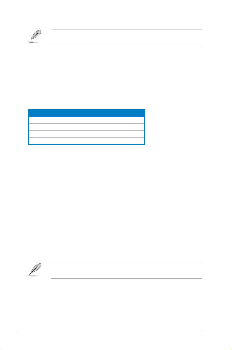
The following item appears only when you set the AI Overclocking item to
[Manual].
CPU Frequency [xxx]
Displays the frequency sent by the clock generator to the system bus and PCI bus.
The value of this item is auto-detected by the BIOS. Use the <+> and <-> keys to
adjust the CPU frequency. You can also type the desired CPU frequency using the
numeric keypad. The values range from 133 to 600. Refer to the table below for
the correct Front Side Bus and CPU External Frequency settings.
FSB / CPU External Frequency Synchronization
Front Side Bus CPU External Frequency
FSB 1333 333 MHz
FSB 1066 266 MHz
FSB 800 200 MHz
FSB 533 133 MHz
PCI Express Frequency [xxx]
Displays the frequency sent by the clock generator to the system bus and PCI bus.
The value of this item is auto-detected by the BIOS. Use the <+> and <-> keys to
adjust the PCIe frequency. You can also type the desired PCIe frequency using the
numeric keypad. The values range from 90 to 150.
FSB Termination Voltage [Auto]
Allows you to set FSB termination voltage or auto for safe mode.
Conguration options: [Auto] [1.20V] [1.30V] [1.40V] 1.50V]
MCH Chipset Voltage [Auto]
Allows you to set MCH chipset voltage or auto for safe mode.
Conguration options: [Auto] [1.125V] [1.175V] [1.225V] [1.275]
The following item appears only when you set the AI Overclocking item to
[OverclockProle].
Overclock Options [Overclock 5%]
Allows you to select the overclock options. Conguration options: [Overclock 5%]
[Overclock 10%] [Overclock 15%] [Overclock 20%] [Overclock 30%]
5-18 Chapter 5: BIOS setup
Page 95
DRAM Frequency [Auto]
Allows you to set the DDR2 operating frequency. Conguration options: [Auto]
[667 MHz] [800 MHz] [1066MHz]
The following table shows the DRAM Frequency options that appear when the
FSB value is 1333, 1066, and 800.
FSB
Auto 667MHz 800MHz 1066MHz
1333 v v v v
1066 v v v v
800 v v v
Selecting a very high DRAM frequency may cause the system to become
unstable! If this happens, revert to the default setting.
DRAM Frequency
Memory Over Voltage [Auto]
Allows you to adjust Memory Over voltage and each step is 6.25mV
SB1.5V Voltage [Auto]
Allows you to set the SB voltage. Conguration options: [Auto] [1.5V] [1.57V]
[1.64V] [1.71V]
SB1.1V Voltage [Auto]
Allows you to set the SB voltage. Conguration options: [Auto] [1.126V] [1.196V]
[1.266V] [1.336V]
Setting a very high voltage may damage the component permanently, and
setting a very low voltage may cause the system to become unstable.
CPU Voltage [Auto]
Allows you to set the CPU VCore voltage. The values range from 0.8500V to 1.55V
with a 0.00625V interval. Conguration options: [Auto]
Setting a very high voltage may damage the component permanently, and
setting a very low voltage may cause the system to become unstable.
ASUS V-Series P5P43 5-19
Page 96

5.4.2 CPUConguration
The items in this menu show the CPU-related information that the BIOS
automatically detects.
Advanced
Congure advanced CPU settings
Module Version: 3D.06
Manufacturer: Intel
Brand String: Intel(R) Core(TM)2 CPU 6300 @ 1.86GHz
Frequency: 1.86GHz
FSB Speed: 1066MHz
Cache L1: 64 KB
Cache L2: 2048 KB
Ratio Status: Unlocked (Max:07.0, Min:06.0)
Ratio Actual Value:7
CPUID: 6F2
Ratio CMOS Setting [Auto]
C1E Support [Enabled]
Max CPUID Value Limit [Disabled]
Intel(R) Virtualization Tech [Enabled]
CPU TM function [Enabled]
Execute Disable Bit [Enabled]
Intel(R) SpeedStep(TM) Tech. [Enabled]
BIOS SETUP UTILITY
Sets the ratio between
CPU Core Clock and the
FSB Frequency.
NOTE: If an invalid
ratio is set in CMOS
then actual and
setpoint values may
differ.
NOTE:
Please Key in ratio
numbers directly!
Ratio CMOS Setting [Auto]
Sets the ratio between CPU Core Clock and the FSB frequency. Conguration
options: [Auto].
If an invalid ratio is set in CMOS then actual and setpoint values my differ.
Key in ratio numbers directly.
C1E Support [Enabled]
Allows you to enable or disable Inter CPU Enhanced Halt (C1E) function, a
CPU power-saving function in system halt state. When enabled, the CPU core
frequency and voltage will be reduced during the system halt state to decrease
power consumption. Conguration options: [Disabled] [Enabled]
Max CPUID Value Limit [Disabled]
Allows you to determine whether to limit CPUID maximum value. Set this item to
[Disabled] for Windows XP operating system; set this item to [Enabled] for legacy
operating system such as Windows NT4.0. (Default: Disabled)
Conguration options: [Disabled] [Enabled]
5-20 Chapter 5: BIOS setup
Page 97

Intel® Virtualization Technology [Enabled]
Enables or disables Intel® Virtualization Technology. Virtualization enhanced by
Intel® Virtualization Technology allows a platform to run multiple operating systems
and applications in independent partitons. With virtualization, one computer
system can function as multiple virtual systems. Conguration options: [Enabled]
[Disabled]
CPU TM function [Enabled]
Enables or disables Intel® CPU Thermal Monitor (TM) function, a CPU overheating
protection function. When enabled, the CPU core frequency and voltage are
reduced when the CPU overheats. Conguration options: [Disabled] [Enabled]
Execute Disable Bit [Enabled]
Enables or disables Intel® Execute Disable Bit function. This function enhance
protection of your computer, reducing exposure to viruses and malicious
buffer overow attacks when working with its supporting software and system.
Conguration options: [Disabled] [Enabled]
The following item appears only when you installed an Intel® Pentium® 4 or later
CPU that supports the Enhanced Intel SpeedStep® Technology (EIST).
Intel® SpeedStep™ Technology [Enabled]
Allows you to use the Enhanced Intel® SpeedStep® Technology. When set to
[Enabled], you can adjust the system power settings in the operating system to
use the EIST feature. Set this item to [Disabled] if you do not want to use the
EIST. Conguration options: [Enabled] [Disabled]
ASUS V-Series P5P43 5-21
Page 98
5.4.3 Chipset
The Chipset menu allows you to change the advanced chipset settings. Select an
item then press <Enter> to display the sub-menu.
Advanced Chipset Settings
WARNING: Setting wrong values in below sections
may cause system to malfunction.
North Bridge Conguration
South Bridge Conguration
Congure North Bridge
features.
NorthBridgeConguration
North Bridge Chipset Conguration
Memory Remap Feature [Enabled]
Congure DRAM Timing by SPD [Enabled]
Initiate Graphic Adapter [PEG/PCI]
Options
Options
128MB
256MB
Memory Remap Feature [Disabled]
Allows you to enable or disable the remapping of overlapped PCI memory above
the total physical memory. We recommend that you set this item to Enabled when
you install 4GB memory. Conguration options: [Enabled] [Disabled]
CongureDRAMTimingbySPD[Enabled]
Allows you to enable or disable congurating DRAM Timing by SPD. Conguration
options: [Enabled] [Disabled]
5-22 Chapter 5: BIOS setup
Page 99

Initiate Graphic Adapter [PEG/PCI]
Allows you to select the graphics controller as the primary boot device.
Conguration options: [PCI/PEG] [PEG/PCI]
SouthBridgeConguration
South Bridge Chipset Conguration
Audio Controller [Enabled]
Front Panel Type [HD Audio]
Options
Audio Controller [Enabled]
Allows you to set the audio controller. Conguration options: [Enabled] [Disabled]
Front Panel Support Type [HD Audio]
Allows you to select the front panel support type. If High Denition Audio
Front Panel used, please set HD Audio mode. Conguration options: [AC97]
[HD Audio]
5.4.4 OnboardDevicesConguration
Onboard Device Conguration
Onboard PCIEX GbE Lan1 [Enabled]
LAN1 Option ROM [Disabled]
OnBoard PCIEX GbE Lan2 [Enabled]
LAN2 Option ROM [Disabled]
J-Micron eSATA/PATA Controller [Enabled]
Controller Mode [IDE]
JMicron SATA/RAID OptRom [Enabled]
1394 Controller [Enabled]
Serial Port1 Address [3F8/IRQ4]
Parallel Port Address [378]
Parallel Port Mode [ECP]
ECP Mode DMA Channel [DMA3]
Parallel Port IRQ [IRQ7]
Onboard PCIEX GbE LAN_
Enable/Disable
ASUS V-Series P5P43 5-23
Page 100

Onboard PCIEX GbE Lan1 [Enabled]
Allows you to enable or disable the onboard PCIEX GbE LAN controller.
Conguration options: [Enabled] [Disabled]
LAN1 Option ROM [Disabled]
Allows you to enable or disable the LAN option ROM in the onboard LAN
controller. This item appears only when the Onboard LAN item is set to
Enabled. Conguration options: [Disabled] [Enabled]
Onboard PCIEX GbE Lan2 [Enabled]
Allows you to enable or disable the onboard PCIEX GbE LAN controller.
Conguration options: [Enabled] [Disabled]
LAN2 Option ROM [Disabled]
Allows you to enable or disable the LAN option ROM in the onboard LAN
controller. This item appears only when the Onboard LAN item is set to
Enabled. Conguration options: [Disabled] [Enabled]
J-Micron eSATA/PATA Controller [Enabled]
Allows you to enable or disable J-Micron eSATA/PATA controller.
Conguration options: [Enabled] [Disabled]
Controller Mode [IDE]
Allows you to select the controller mode.
Conguration options: [RAID] [IDE] [AHCI]
JMicron SATA/RAID OptRom [Enabled]
Allows you to enable or disable JMicron SATA/RAID OptRom.
Conguration options: [Enabled] [Disabled]
1394 controller [Enabled]
Allows you to enable or disable 1394 controller.
Conguration options: [Enabled] [Disabled]
Serial Port1 Address [3F8/IRQ4]
Allows you to select the Serial Port1 base address.
Conguration options: [Disabled] [3F8/IRQ4] [2F8/IRQ3] [3E8/IRQ4] [2E8/IRQ3]
Parallel Port Address [378]
Allows you to select the Parallel Port base addresses. Conguration options:
[Disabled] [378] [278] [3BC]
5-24 Chapter 5: BIOS setup
 Loading...