

Page 1

R
V3000 Series
AGP&PCI Graphics Cards
USER’S MANUAL
Hardware & Video Drivers
AGP-V3000/TV
AGP-V3000
3DP-V3000/TV
3DP-V3000
AGP-V3000ZX/TV/4M
AGP-V3000ZX/4M
AGP-V3000ZX/TV
AGP-V3000ZX
Page 2

USER’S NOTICE
No part of this manual, including the products and software described in it, may be reproduced, transmitted, transcribed, stored in a retrieval system, or translated into any language
in any form or by any means, except documentation kept by the purchaser for backup purposes, without the express written permission of ASUSTeK COMPUTER INC. (“ASUS”).
ASUS PROVIDES THIS MANUAL “AS IS” WITHOUT WARRANTY OF ANY KIND,
EITHER EXPRESS OR IMPLIED, INCLUDING BUT NOT LIMITED TO THE IMPLIED
W ARRANTIES OR CONDITIONS OF MERCHANTABILITY OR FITNESS FOR A P ARTICULAR PURPOSE. IN NO EVENT SHALL ASUS, ITS DIRECT ORS, OFFICERS, EMPLOYEES OR AGENTS BE LIABLE FOR ANY INDIRECT, SPECIAL, INCIDENTAL,
OR CONSEQUENTIAL DAMAGES (INCLUDING DAMAGES FOR LOSS OF PROFITS, LOSS OF BUSINESS, LOSS OF USE OR DATA, INTERRUPTION OF BUSINESS
AND THE LIKE), EVEN IF ASUS HAS BEEN ADVISED OF THE POSSIBILITY OF
SUCH DAMAGES ARISING FROM ANY DEFECT OR ERROR IN THIS MANUAL OR
PRODUCT .
Product warranty or service will not be extended if: (1) the product is repaired, modified or
altered, unless such repair, modification of alteration is authorized in writing by ASUS; or
(2) the serial number of the product is defaced or missing.
Products and corporate names appearing in this manual may or may not be registered trademarks or copyrights of their respective companies, and are used only for identification or
explanation and to the owners’ benefit, without intent to infringe.
• Intel, LANDesk, and Pentium are registered trademarks of Intel Corporation.
• Windows and MS-DOS are registered trademarks of Microsoft Corporation.
• Adobe and Acrobat are registered trademarks of Adobe Systems Incorporated.
The product name and revision number are both printed on the product itself. Manual revi-
sions are released for each product design represented by the digit before and after the period
of the manual revision number. Manual updates are represented by the third digit in the
manual revision number.
For previous or updated manuals, BIOS, drivers, or product release information, contact ASUS
at http://www.asus.com.tw or through any of the means indicated on the following page.
SPECIFICATIONS AND INFORMATION CONTAINED IN THIS MANUAL ARE FURNISHED FOR INFORMATIONAL USE ONLY, AND ARE SUBJECT TO CHANGE AT
ANY TIME WITHOUT NOTICE, AND SHOULD NOT BE CONSTRUED AS A COMMITMENT BY ASUS. ASUS ASSUMES NO RESPONSIBILITY OR LIABILITY FOR
ANY ERRORS OR INACCURACIES THA T MAY APPEAR IN THIS MANUAL, INCLUDING THE PRODUCTS AND SOFTWARE DESCRIBED IN IT.
Copyright © 1999 ASUSTeK COMPUTER INC. All Rights Reserved.
Product Name: ASUS V3000 Series
Manual Revision: 2.20 E298B
Release Date: January 1999
2
ASUS V3000 Series User’s Manual
Page 3

ASUS CONTACT INFORMATION
ASUSTeK COMPUTER INC. (Asia-Pacific)
Marketing
Address: 150 Li-Te Road, Peitou, Taipei, Taiwan 112
Telephone: +886-2-2894-3447
Fax: +886-2-2894-3449
Email: info@asus.com.tw
Technical Support
Tel (English): +886-2-2894-3447 ext. 706
Tel (Chinese): +886-2-2894-3447 ext. 701
Fax: +886-2-2895-9254
Email: tsd@asus.com.tw
Newsgroup: news2.asus.com.tw
WWW: www.asus.com.tw
FTP: ftp.asus.com.tw/pub/ASUS
ASUS COMPUTER INTERNATIONAL (America)
Marketing
Address: 6737 Mowry Avenue, Mowry Business Center, Building 2
Newark, CA 94560, USA
Fax: +1-510-608-4555
Email: info-usa@asus.com.tw
Technical Support
Fax: +1-510-608-4555
BBS: +1-510-739-3774
Email: tsd-usa@asus.com.tw
WWW: www.asus.com
FTP: ftp.asus.com.tw/pub/ASUS
ASUS COMPUTER GmbH (Europe)
Marketing
Address: Harkort Str. 25, 40880 Ratingen, BRD, Germany
Telephone: 49-2102-445011
Fax: 49-2102-442066
Email: info-ger@asus.com.tw
Technical Support
Hotline: 49-2102-499712
BBS: 49-2102-448690
Email: tsd-ger@asus.com.tw
WWW: www.asuscom.de
FTP: ftp.asuscom.de/pub/ASUSCOM
ASUS V3000 Series User’s Manual 3
Page 4

CONTENTS
I. Introduction.....................................................................................7
Key Benefits ....................................................................................7
Features ............................................................................................7
II. Hardware Installation ...................................................................8
ASUS AGP-V3000 Layout (AGP Bus) ...........................................8
ASUS AGP-V3000/TV Layout (AGP Bus).....................................9
ASUS 3DP-V3000 Layout (PCI Bus) ...........................................10
ASUS 3DP-V3000/TV Layout (PCI Bus) .....................................11
ASUS AGP-V3000ZX / ASUS AGP-V3000ZX/4M
Layout (AGP Bus)....................................................................12
ASUS AGP-V3000ZX/TV / ASUS AGP-V3000ZX/TV/4M
Layout (AGP Bus)....................................................................13
III. Windows 95/98 ............................................................................14
Installation Procedures .............................................................14
New Systems ......................................................................14
Systems with Existing VGA Card ......................................14
Operating System Requirements ...................................................15
Windows 95..............................................................................15
Windows 98..............................................................................15
Install V3000 Series Driver (existing ASUS V3000) ....................16
Install V3000 Series Driver (replacing other VGA card) ..............20
Display Properties (desktop utilities).............................................22
Advanced Menu .......................................................................22
Color Correction Menu ............................................................ 23
Information Menu ....................................................................23
TV Out Menu (AGP-V3000ZXTV only).................................24
Settings Menu...........................................................................24
Hotkey Menu............................................................................25
Monitor Menu ..........................................................................25
Refresh Rate Menu...................................................................26
4
ASUS V3000 Series User’s Manual
Page 5

CONTENTS
Install DirectX6..............................................................................26
Install VGARTD (AGP only) ........................................................28
Install ASUS LIVE3000 (for TV models only) .............................31
Using ASUS LIVE3000 (for TV models only)........................31
Show/Hide Video Source Option .......................................32
Video Capture Driver.....................................................................32
Remove V3000 Series Driver ........................................................33
Using Windows 95/98 Control Panel .......................................33
IV. Microsoft Windows NT ..............................................................35
Windows NT 4.0 ............................................................................35
Installation Procedures .......................................................35
V. Display Information .....................................................................36
VI. Troubleshooting..........................................................................38
Description ...............................................................................38
Recommended Action ..............................................................38
ASUS V3000 Series User’s Manual 5
Page 6

FCC & DOC COMPLIANCE
Federal Communications Commission Statement
This device complies with FCC Rules Part 15. Operation is subject to the following
two conditions:
• This device may not cause harmful interference, and
• This device must accept any interference received, including interference that
may cause undesired operation.
This equipment has been tested and found to comply with the limits for a Class B
digital device, pursuant to Part 15 of the FCC Rules. These limits are designed to
provide reasonable protection against harmful interference in a residential installation. This equipment generates, uses and can radiate radio frequency energy and, if
not installed and used in accordance with manufacturer’s instructions, may cause
harmful interference to radio communications. However , there is no guarantee that
interference will not occur in a particular installation. If this equipment does cause
harmful interference to radio or television reception, which can be determined by
turning the equipment off and on, the user is encouraged to try to correct the inter ference by one or more of the following measures:
• Reorient or relocate the receiving antenna.
• Increase the separation between the equipment and receiver.
• Connect the equipment to an outlet on a circuit different from that to which
the receiver is connected.
• Consult the dealer or an experienced radio/TV technician for help.
WARNING! The use of shielded cables for connection of the monitor to the
graphics card is required to assure compliance with FCC regulations. Changes
or modifications to this unit not expressly approved by the party responsible for
compliance could void the user’s authority to operate this equipment.
Canadian Department of Communications Statement
This digital apparatus does not exceed the Class B limits for radio noise emissions
from digital apparatus set out in the Radio Interference Regulations of the Canadian Department of Communications.
6
ASUS V3000 Series User’s Manual
Page 7

I. Introduction
Thank you for purchasing an ASUS V3000 Series Graphics & Video Accelerator.
With the ST/nV idia RIVA 128™/128ZX™ built-in, the ASUS V3000 Series provides
you with fast acceleration in both 2D/3D graphics and high quality scalable video
playback, which can fully support 3D Gaming and Multimedia Applications.
Key Benefits
• Supports professional graphics design, gaming, learning, and business applications
• Flicker free, high refresh rates reduce eye strain
• Powerful 3D rendering
• Crisp, realistic images
• Striking cinema-quality video
Features
• Built-in ST/nVidia RIVA 128™/128ZX™ 128-bit 3D Multimedia Accelerator
• User-friendly Installation for Windows 95/98.
• Acceleration for W indows 95/98 APIs, including Direct3D, DirectDraw (+ VPE),
and OpenGL-ICD
• Acceleration for Windows NT APIs, including Direct3D, DirectDraw, and
OpenGL-ICD
• Massive array of floating point Geometry Processing Units
• 128-bit 2D/GUI/DirectDraw Acceleration
• Windows 95/98 Video for Windows video capture driver included
• Video Acceleration (including acceleration for MPEG-I, MPEG-II, and Indeo)
• X and Y up and down video scaling
• Excellent performance at high resolutions and color depths
• VESA VBE 3.0 Compliant
• Onboard video capture and TV out (TV models only)
Features
I. Introduction
AGP-V3000, AGP-V3000/TV, and 3DP-V3000
• 4MB 128-bit 100MHz SGRAM frame buffer interface
• 230MHz Palette-DAC
• AGP 1.0 (1x mode) or PCI 2.1 Bus Interface
AGP-V3000ZX, AGP-V3000ZXTV and AGP-V3000ZX/4M, AGP-V3000ZXTV/4M
• 8MB and 4MB (4M models) 128-bit 100MHz SGRAM frame buffer interface
• 250MHz Palette-DAC
• AGP 1.0 (2x mode) Bus Interface
IMPORTANT! External devices and ASUS Video cards both have NTSC and
PAL versions. You must make sure that all your devices and the ASUS Video
card are of the same type or else you will not have video capabilities.
7ASUS V3000 Series User’s Manual
Page 8
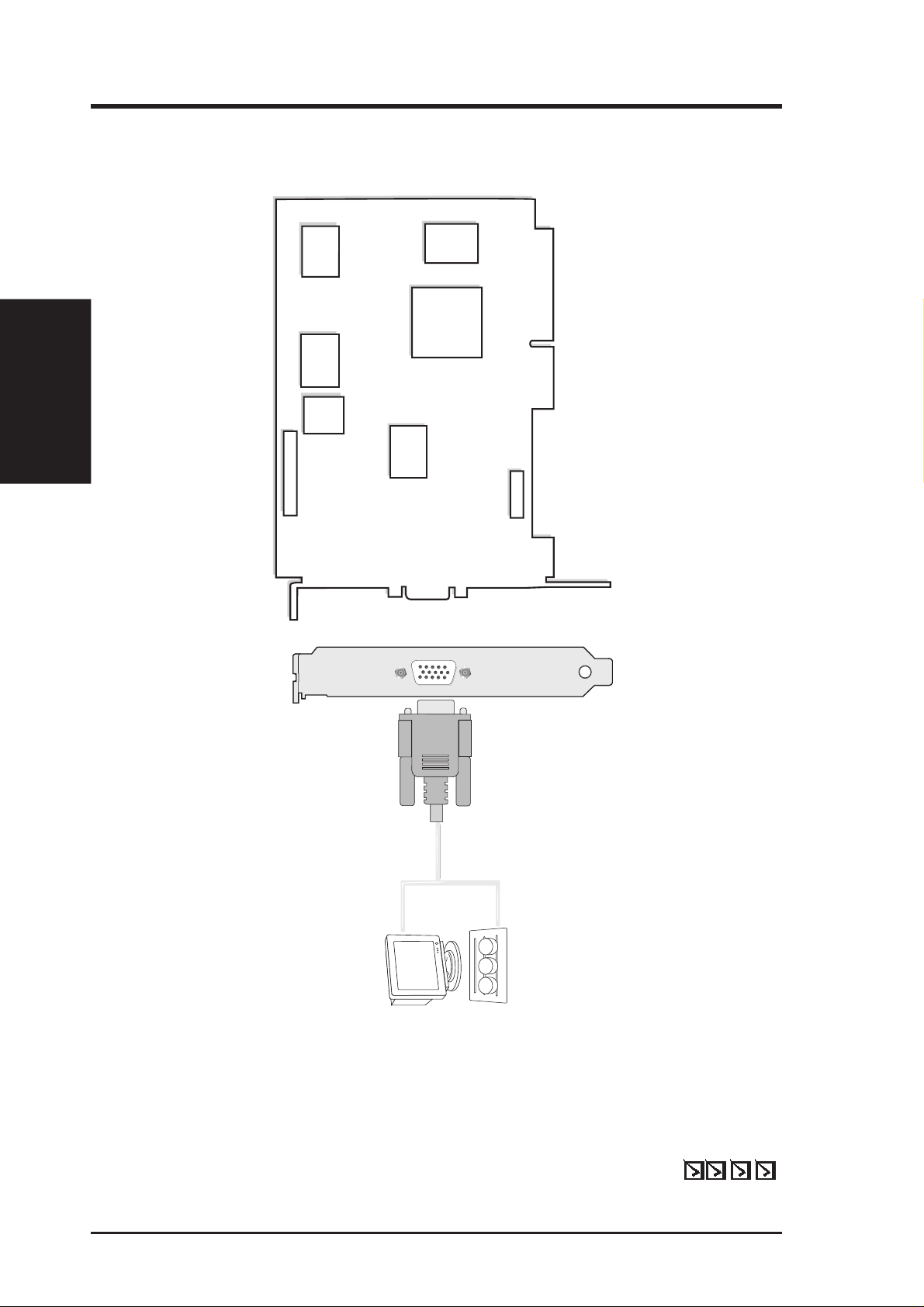
II. Installation
VGA Output
SGRAM
SGRAM
SGRAM
SGRAM
VIP Connector B
VIP Connector A
VGA Monitor
output (15pin)
(standard)
ST/nVidia
Riva128
TM
3D Chipset
VGA
BIOS
Projector
AGP-V3000
II. Hardware Installation
Note: AGP-V3000 does not have video-in and TV-out con-
nectors. The corresponding video/TV utilities will also be
excluded.
ASUS AGP-V3000 Layout (AGP Bus)
PDF)
®
Acrobat
®
ASUS AGP-V3000
This User’s Manual
Manual (Adobe
ASUS V3000 Series Driver & Utility CD
Item Checklist
ASUS V3000 Series User’s Manual8
Page 9

II. Hardware Installation
VGA Monitor
output (15pin)
(standard)
CCD/camcorder
input (RCA)
(video model)
composite/TV
output (RCA)
(video model)
Tuner/TV Box Input
(7pin) (video model)
SVHS/TV output
(7pin) (video model)
VIP Connector A
VIP Connector B
SGRAM
SGRAM
SGRAM
SGRAM
ST/nVidia
Riva128
TM
3D Chipset
Composite (RCA) Input
Video Input (ASUS Video)
7pin S compatible)
VGA Output
S-Video Output
Composite (RCA) Output
Projector
ASUS TV Box
CATV
®
II. Installation
AGP-V3000/TV
and cannot be connected at the same time.
Notes:
devices cannot be connected at the same time on this card.
• Use the same standard for all devices.
• VGA compatible devices and video displaying/recording
•
ASUS AGP-V3000/TV Layout (AGP Bus)
ASUS AGP-V3000/TV (PAL or NTSC)
Item Checklist
PDF)
®
Acrobat
®
Video-in and TV-out cables
This User’s Manual
Manual (Adobe
ASUS V3000 Series Driver & Utility CD
9ASUS V3000 Series User’s Manual
Page 10
II. Installation
VGA
BIOS
SGRAM
SGRAM
SGRAM
VIP Connector A
VIP Connector B
ST/nVidia
Riva128
TM
3D Chipset
SGRAM
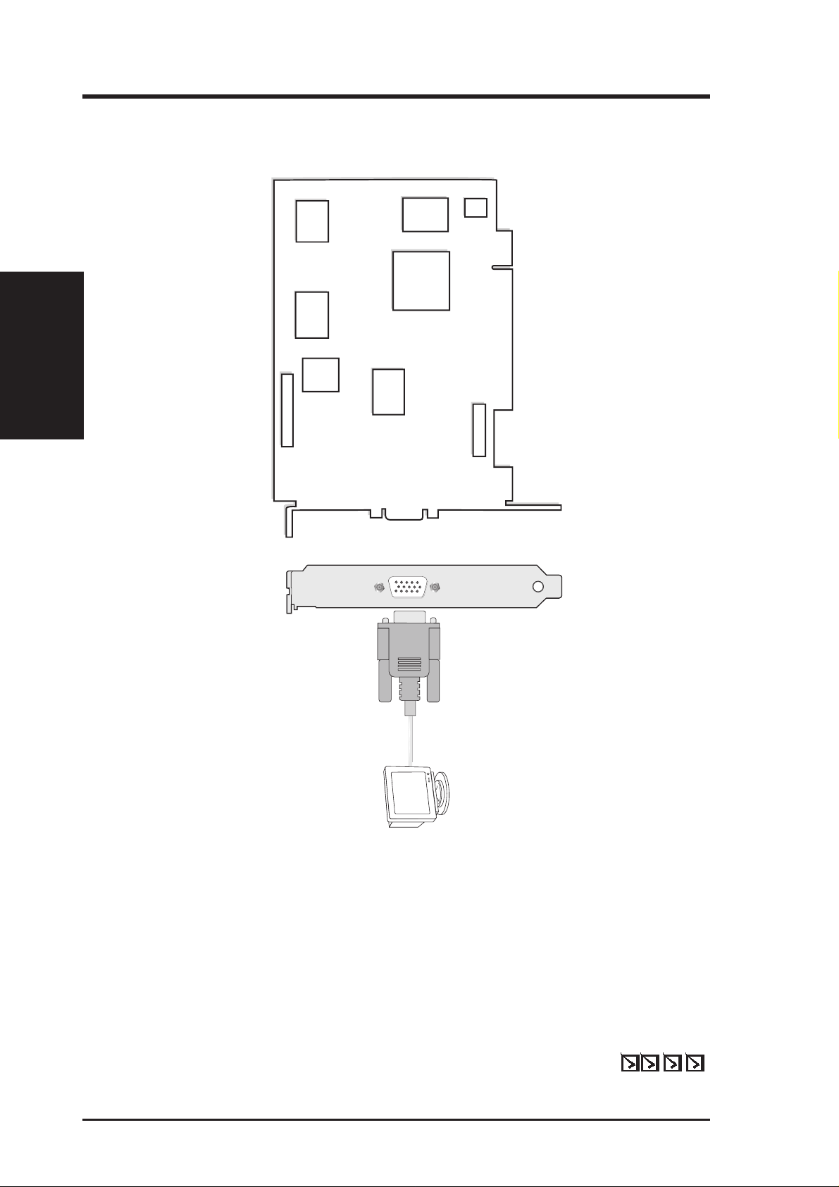
VGA Output
VGA Monitor
output (15pin)
(standard)
3DP-V3000
II. Hardware Installation
Note: 3DP-V3000 does not have video-in and TV-out con-
nectors. The corresponding video/TV utilities will also be
excluded.
ASUS 3DP-V3000 Layout (PCI Bus)
PDF)
®
Acrobat
®
ASUS 3DP-V3000
This User’s Manual
Manual (Adobe
ASUS V3000 Series Driver & Utility CD
Item Checklist
ASUS V3000 Series User’s Manual10
Page 11
SGRAM
SGRAM
SGRAM
VIP Connector A
VIP Connector B
VGA Monitor
output (15pin)
(standa
rd)
CCD/camcorder
input (RCA)
(video model)
composite/TV
output (RCA)
(video model)
Tuner/TV Box Input
(7pin) (video model)
SVHS/TV output
(7pin) (video model)
ST/nVidia
Riva128
TM
3D Chipset
SGRAM
Composite (RCA) Input
Video Input (ASUS Video)
7pin S compatible)
VGA Output
S-Video Output
Composite (RCA) Output
VGA
BIOS
Projector
ASUS TV Box
CATV
®
II. Hardware Installation
II. InstallationII. Installation
3DP-V3000/TV
cannot be connected at the same time.
Notes:
• Use the same standard for all devices.
• VGA compatible devices and video displaying/recording
ASUS 3DP-V3000/TV Layout (PCI Bus)
®
®
devices cannot be connected at the same time on this card.
• and
PDF)
Acrobat
ASUS 3DP-V3000/TV (PAL or NTSC)
Video-in and TV-out cables
This User’s Manual
Manual (Adobe
ASUS V3000 Series Driver & Utility CD
Item Checklist
11ASUS V3000 Series User’s Manual
Page 12

AGP-V3000ZX
VGA Monitor
output (15pin)
(standard)
VGA Output
ST/nVidia
Riva128ZX
TM
3D Chipset
SGRAM
SGRAM
SGRAM
SGRAM
VGA
BIOS
VIP Connector A
VIP
Connector B
II. Installation
II. Hardware Installation
Layout (AGP Bus)
ASUS AGP-V3000ZX
Note: AGP-V3000ZX or AGP-V3000ZX/4M does not have
video-in and TV-out connectors. The corresponding video/
TV utilities will also be excluded.
ASUS AGP-V3000ZX/4M
PDF)
®
Acrobat
®
ASUS AGP-V3000ZX or ASUS AGP-V3000ZX/4M
This User’s Manual
Manual (Adobe
ASUS V3000 Series Driver & Utility CD
Item Checklist
ASUS V3000 Series User’s Manual12
Page 13

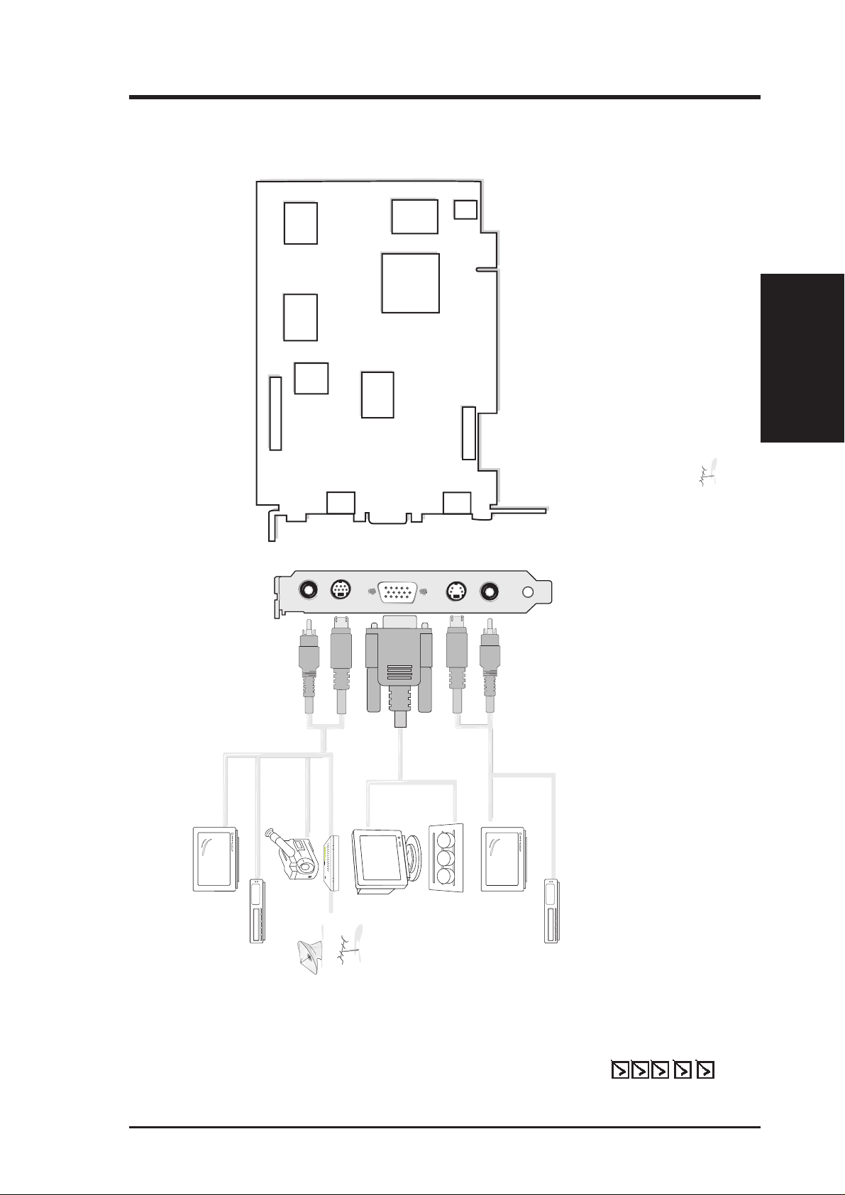
II. Hardware Installation
VGA Monitor
output (15pin)
(standard)
CCD/camcorder
input (RCA)
(video model)
composite/TV
output (RCA)
(video model)
Tuner/TV Box Input
(7pin) (video model)
SVHS/TV output
(7pin) (video model)
ST/nVidia
Riva128ZX
TM
3D Chipset
SGRAM
SGRAM
SGRAM
SGRAM
VGA
BIOS
JP1 JP2
TV-out
Composite (RCA) Input
Video Input (ASUS Video)
7pin S compatible)
VGA Output
S-Video Output
Composite (RCA) Output
VIP Connector A
VIP
Connector B
Projector
123
ASUS TV Box
CATV
®
JP1
JP2
1
2
3
NTSC
JP1
JP2
1
2
3
PAL
JP1
JP2
1
2
3
Disable
Layout (AGP Bus)
ASUS AGP-V3000ZX/TV
ASUS AGP-V3000ZX/TV/4M
II. Installation
AGP-V3000ZX/TV
cannot be connected at the same time.
Notes:
devices can be connected at the same time on this card.
• Use the same TV standard for all devices.
• VGA compatible devices and video displaying/recording
• and
• Use JP1 and JP2 to select the boot up TV-out format.
PDF)
®
ASUS AGP-V3000ZXTV (PAL or NTSC) or
ASUS AGP-V3000ZXTV/4M (PAL or NTSC)
Item Checklist
Acrobat
®
Video-in and TV-out cables
This User’s Manual
Manual (Adobe
ASUS V3000 Series Driver & Utility CD
13ASUS V3000 Series User’s Manual
Page 14

NOTE: The ASUS AGP-V3000, AGP-V3000/TV, AGP-V3000ZX and AGP-
V3000ZXTV can only be installed in motherboards with an AGP slot. The ASUS
3DP-V3000 and 3DP-V3000/TV can be installed in standard PCI motherboards.
III. Windows 95/98
Procedures
III. Windows 95/98
WARNING! Computer boards and components contain very delicate Integrated
Circuit (IC) chips. To protect the computer board and other components against
damage from static electricity, you must follow some precautions.
1. Make sure that you unplug your power supply when adding or removing
expansion cards or other system components. Failure to do so may cause
severe damage to both your motherboard and expansion cards.
2. Keep all components, such as the host adapter, in its antistatic bag until you
are ready to install it.
3. Use a grounded wrist strap before handling computer components. If you do
not have one, touch both of your hands to a safely grounded object or to a
metal object, such as the power supply case. Hold components by the edges
and try not to touch the IC chips, leads, or circuitry.
4. Place components on a grounded antistatic pad or on the bag that came with the
component whenever the components are separated from the system.
Installation Procedures
New Systems
1. Unplug all electrical cords on your computer.
2. Remove the system unit cover.
3. Locate the AGP or PCI bus expansion slot. Make sure this slot is unobstructed.
4. Remove the corresponding expansion slot cover from the computer chassis.
5. Ground yourself to an antistatic mat or other grounded source (see WARNING!).
6. Pick up the board (still in its sleeve) by grasping the edge bracket with one hand
and then remove the plastic sleeve.
7. Position the card directly over the AGP slot and insert one end of the board in
the slot first. Firmly but gently press the bus connector on the bottom of the card
down into the slot. Be sure the metal contacts on the bottom of the host adapter
are securely seated in the slot.
8. Anchor the board’s mounting bracket to the computer chassis using the screw
from the slot cover that you set aside previously.
9. Replace the cover on the system unit.
10. Connect your analog monitor’s 15-pin VGA connector to the card and fasten the
retaining screws (if any).
11. Connect other cables and devices if available -You are now ready to install the
software drivers and utilities.
Systems with Existing VGA Card
1. Install the ASUS V3000 Series display drivers with your current VGA card.
2. Shut down your computer and unplug all electrical cords.
3. Replace the existing VGA card with the ASUS V3000 Series graphics card.
4. Restart your computer — the ASUS V3000 Series graphics card should be automatically detected and the display drivers automatically updated.
ASUS V3000 Series User’s Manual14
Page 15

III. Windows 95/98
Operating System Requirements
IMPORTANT! This card requires its own IRQ to work normally. If you have
problems during installation, please check your BIOS setting or motherboard
jumpers to make sure that “VGA INT/IRQ” has been enabled.
Windows 95
To take advantage of all the AGP features, you must use Windows 95 OSR2.0, install the USB upgrade and then install the VGARTD driver for the corresponding
chipset on your motherboard. (see III. Windows 95/98 “Install VGARTD”).
Note: This is not necessary for the 3DP-V3000/TV.
To install Win95 OSR2.0 with USB, you must have OSR2.0 installed already. Otherwise, first install OSR2.0 and then use the USB support update (you must use the
same update language of your W indows language). On the April 1997 MSDN Disc1 “Windows 95, SDKs, and Tools”, OSR2.0 is found in “\OSR2” while the USB
support update is found in “\OSR2\USBSUPP”. To determine the installed version
of the operating system, look in the registry at:
HKEY_LOCAL_MACHINE\SOFTWARE\Microsoft\Windows\CurrentVersion\Version
HKEY_LOCAL_MACHINE\SOFTW ARE\Microsoft\W indows\CurrentVersion\V ersionNumber
OSR2.0 with USB has:
Version “Windows 95” and VersionNumber “4.03.1212” or “4.03.1214”.
Windows 98
Only Windows 98 Beta3 or later supports full Direct3D and AGP features. If you
are not using Beta3 or later, you must upgrade your Windows before installing the
AGP display driver.
NOTE: Windows 98 includes VGARTD for the major chipsets but it is recommended that you install VGARTD from the V3000 Series installation CD to make
sure that you have the latest version of VGARTD.
Requirements
III. Windows 95/98
NOTE: This Manual assumes that your CD-ROM disc drive is drive D: and that MS
Windows is in “c:\windows”. Replace either with the actual location, if necessary.
15ASUS V3000 Series User’s Manual
Page 16

Install V3000 Series Driver (existing ASUS V3000)
Follow the steps below if you are using a V3000 Series graphics card with AGP bus
or if you want to install it in Windows 98.
Note: “New hardware found” refers to the prompt for drivers when installing Windows 95/98 with the ASUS V3000 Series VGA card already installed. This Manual
assumes that your CD-ROM disc drive is drive D: and that Windows 95/98 is in
C:\windows. Replace either with the actual location, if necessary.
1. When installing W indows 95/98, a New Hardware Found window will appear:
III. Windows 95/98
Install Driver
III. Windows 95/98
Select Do not install a driver and go to step 3.
When installing W indows 95 OSR 2.0, the Update Device Driver Wizard window will appear:
This wizard will complete the installation of the Standard PCI Graphics Adapter
(VGA). Click
Next > to let Windows search for an updated driver.
WARNING! Only click Next >. The system will hang if you click Cancel!
ASUS V3000 Series User’s Manual16
Page 17

III. Windows 95/98
2. Click Finish to install the VGA driver. You will then be asked for your Win-
dows95/98 CD in order to complete the VGA driver installation.
If you do not have your CD handy, direct the installation path to your
\Windows\System directory . W indows will prompt you to restart your windows.
Choose No.
3. Insert your CD or double click on your CD drive icon in My Computer to bring
up the autorun screen or run Setup.exe in the root directory of the CD.
4. From the Setup panel, click VGA Driver and follow the installation steps.
Install Driver
III. Windows 95/98
17ASUS V3000 Series User’s Manual
Page 18

5. When the Welcome window appears, click Next > to install V3000 Series dis-
III. Windows 95/98
Install Driver
III. Windows 95/98
play drivers on your computer.
The install program will detect whether you are using OSR2.0 with USB
(OSR2.1). If not, a message will be given to exit the install program (Click Yes)
or continue (Click No).
ASUS V3000 Series User’s Manual18
Page 19

III. Windows 95/98
6. When the Check Setup Information window appears, click
the file transfer.
The Installing Microsoft DirectX6 dialog box will automatically appear be-
cause the V3000 Series display driver requires DirectX 6 to have access to the
advanced 3D features.
Next > to begin
This box indicates that the Setup program is searching for the updated DirectX
Runtime Components and updating as necessary.
Install Driver
III. Windows 95/98
19ASUS V3000 Series User’s Manual
Page 20

Install V3000 Series Driver (replacing other VGA card)
If you wish to replace an existing VGA card with an ASUS V3000 Series graphics
card, the current display drivers must be replaced first (see II. Hardware Installa-
tion “Systems with Existing VGA Card”).
Note: The following procedure works only for W indows 95. For W indows 98 users,
follow the procedures for “Install V3000 Series Driver (existing ASUS 3000)”.
1. Insert your CD or double click on your CD drive icon in My Computer to bring
up the autorun screen or run Setup.exe in the root directory of the CD.
III. Windows 95/98
Replacing Card
III. Windows 95/98
2. From the Setup panel, click VGA Driver and the Welcome window will appear.
3. Click Next > to install the V3000 Series display drivers on your computer.
ASUS V3000 Series User’s Manual20
Page 21

III. Windows 95/98
4. The install program will detect whether you are using OSR2.0 with USB
(OSR2.1). If not, a message will be given to exit the install program (Click Yes)
or continue (Click No).
The Installing Microsoft DirectX6 dialog box will automatically appear be-
cause the V3000 Series display driver requires DirectX6 to have access to the
advanced 3D features. Click
Next > to begin file transfer.
5. The Setup pr ogram will then search for the updated DirectX Runtime Compo-
nents and update as necessary.
Replacing Card
III. Windows 95/98
6. After all drivers are installed, power off your system and replace your VGA card
with the ASUS V3000 Series card. Restart your computer , and the drivers should
be installed automatically.
21ASUS V3000 Series User’s Manual
Page 22

III. Windows 95/98
Display Properties (desktop utilities)
T o run Desktop Utilities, click the right mouse button on the W indows 95/98 desktop,
then choose Properties in the list.
Advanced Menu
This menu provides some advanced settings for Direct3D. You can set “Texture
Heap” (available only for the 3DP-V3000TV) to maximum value for those texturegreedy applications or games.
Allows customizing of
texture buffer size
Enables/Disables
each Direct3D
III. Windows 95/98
Desktop Utilities
component
Fastest-uses
per-polygon
mipmapping
Best Qualityuses the most
accurate
mipmapping
calculation
Adjusts the size of
the texture buffer
in the system
memory. This
function will be
disabled when
using an AGP
card.
Origin selection for
non-filtering texels
Origin selection for
bilinear filtering texels
Note: The screen displays are provided as examples only and may not reflect the
screen contents displayed on your system.
ASUS V3000 Series User’s Manual22
Page 23

III. Windows 95/98
Color Correction Menu
You can adjust the brightness, contrast, and gamma values of the screen output from the
Color Correction Menu. This function is only available in 16-bit and 32-bit color depth.
Enables/Disables
the color settings
Color mapping chart
Individual channel
adjustment
Restores Color
Correction menu to
default settings
Information Menu
You can lists all the information about the VGA card and video configurations from
the Information Menu.
Desktop Utilities
III. Windows 95/98
Shows AGP memory
info. (will be blank or
warning given if no
AGP card or memory
is found)
Invokes the online
help
23ASUS V3000 Series User’s Manual
Page 24

III. Windows 95/98
TV Out Menu (AGP-V3000ZXTV only)
The TV Out tab will appear if your card came with an S-Video and/or Composite
connector, a TV is connected to one of these connectors (S-Video provides better
quality) and turned on, and you are in any one of these modes: 640x480@60Hz or
800x600@60Hz for NTSC, 640x480@50Hz or 800x600@50Hz for PAL.
Enables/disables TV
output function
Adjusts the brightness
Adjusts the sharpness
III. Windows 95/98
Desktop Utilities
Adjusts the screen
display position on
Adjusts the anti-flicker
Note: If TV output is turned on, the display refresh rate will be forced to 60Hz for NTSC
and 50Hz for PAL. Display Modes will only be available for you to set other frame rates
when you turn off TV output, close the Pr operties dialog box, and then enter it again.
Settings Menu
You can set the resolution, color depth, fonts, and virtual desktop from this menu.
your TV
effect
Video signal selection
TV signal format
Overscan/underscan
selection
Enables/Disables the
virtual desktop
Sets the screen
resolution
Sizes the virtual
desktop
ASUS V3000 Series User’s Manual24
Page 25

III. Windows 95/98
Hotkey Menu
You can define hotkeys for the virtual screen operation from the Hotkey Menu.
Hotkey function item
Enables/Disables
hotkey feature
Key combination
Monitor Menu
You can adjust the screen output on the monitor from the Monitor Menu.
Click to change the onscreen test pattern
Desktop Utilities
III. Windows 95/98
Sets the screen
position
Sets the screen size
The sync polarity setting
Displays the Change
Refresh Rate menu
Restores the Monitor
menu settings to its
defaults
25ASUS V3000 Series User’s Manual
Page 26

Refresh Rate Menu
You can change the refresh rate setting for your monitor from this Menu.
Displays the default
refresh rates
Fine adjustment
of the refresh rate
Test the refresh rate
before applying
III. Windows 95/98
Install DirectX6
III. Windows 95/98
Restores settings to
its defaults
Install DirectX6
Microsoft DirectX6 allows 3D hardware acceleration support in Windows 95/98.
For Software MPEG support in W indows 95/98, you must first install the Microsoft
DirectX6 libraries, and then the MPEG Video Player.
1. Insert your CD or double click on your CD drive icon in My Computer to bring
up the autorun screen or run Setup.exe in the root directory of the CD.
2. From the Setup panel, click DirectX6.0.
ASUS V3000 Series User’s Manual26
Page 27

III. Windows 95/98
The DirectX6 Setup Screen appears
3. Check Direct 3D Hardware Acceleration Enabled and then click the Rein-
stall DirectX button.
4. After reinstalling DirectX6, you will be prompted to restart your machine. Click OK.
Insatall DirectX6
III. Windows 95/98
27ASUS V3000 Series User’s Manual
Page 28

Install VGARTD (AGP only)
1. Insert your CD or double click on your CD drive icon in My Computer to bring
up the autorun screen or run Setup.exe in the root directory of the CD.
2. From the Setup panel, click Vgartd Driver for AGP chipset support from Intel,
SiS, VIA, and ALi. A message appears that only the AGP version requires this
driver installation.
III. Windows 95/98
Install VGARD
III. Windows 95/98
3. A driver detection screen appears to tell you which chipset is detected. Click
OK to install the appropriate driver for your chipset.
Note: Installation dialogs are slightly different for each chipset. Please follow the
instructions to finish the VGARTD installation. The steps provided are for Intel
chipsets.
ASUS V3000 Series User’s Manual28
Page 29

III. Windows 95/98
4. If you selected No..., on the previous screen before clicking OK, you will be
presented with a selection of other drivers. Make your driver selection and click
Install.
5. When the Welcome screen appears, click Next to continue.
6. Once the driver installation is finished, click Finish.
Install VGARTD
III. Windows 95/98
29ASUS V3000 Series User’s Manual
Page 30

(This page was intentionally left blank.)
ASUS V3000 Series User’s Manual30
Page 31

III. Windows 95/98
Install ASUS LIVE3000 (for TV models only)
ASUS LIVE3000 must be installed to use the video-in function on the V3000 Series
accelerator cards.
1. Reinsert your CD or double click on your CD drive icon in My Computer to
bring up the autorun screen or run Setup.exe in the root directory of the CD.
2. From the Setup panel, click ASUS LIVE3000 and follow the self-explanatory
instructions to complete the installation.
After installation, you may run the program through the “Start” button-ProgramsASUS LIVE3000-LIVE3000 or remove the program using the unInstallSHIELD.
Using ASUS LIVE3000 (for TV models only)
Stop
Play
Pause
Video Slider
About
Help
Exit
Minimize
Capture Mode
Live Video Mode
Show/Hide Tuner Panel
Full Screen (Ctrl+S)
Capture Single Frame (F5)
Capture Frames (F6)
Capture Video (F7)
Show/Hide
Video Source Option
Up button
Right button
Left button
Down button
Set Capture File
Open Video File
Video Format
ASUS LIVE3000
III. Windows 95/98
31ASUS V3000 Series User’s Manual
Page 32

Show/Hide Video Source Option
When first using ASUS LIVE3000, you must setup the Video Source. By clicking
the Show/Hide V ideo Source Option button on the panel, you can show or hide the
video source setting.
III. Windows 95/98
ASUS LIVE3000
III. Windows 95/98
You can use the Up or Down arrow buttons on the control panel to select the Video
Connector or the Video Standard. The Left and Right arrow buttons are used for
making selections.
Video Capture Driver
When you install the V3000 Series Windows 95/98 Driver , the video capture driver
will automatically be installed on your system. This video capture driver follows
Microsoft V ideo for Windows standard and can open up to a capture window size of
352x240. It can be used with some applications that use video capture as an option,
such as video conference, net meeting, or digital video authoring applications.
ASUS V3000 Series User’s Manual32
Page 33

III. Windows 95/98
Remove V3000 Series Driver
If you want to install other graphics cards or if you no longer need the V3000 Series
display drivers, you can use one of the following procedures to completely uninstall
the drivers from Windows 95/98 to save disk space.
Using Windows 95/98 Control Panel
1. Click Start, and then point to Settings.
2. Click Control Panel.
3. Double-click the Add/Remove Programs icon.
4. Click the Install/Uninstall tab.
5. Select ASUS VGA driver from the list.
6. Click Add/Remove.
7. You will be warned that files will be deleted. Click Yes to continue.
Remove Driver
III. Windows 95/98
ASUS V3000 Series User’s Manual 33
Page 34

III. Windows 95/98
8. A Remove Shared File? dialog box will ask for confirmation on removing some
shared files. Click Yes To All to remove the shared files.
III. Windows 95/98
Remove Driver
9. You will be warned that shared files may be used by other devices. Click Yes to
10. This progress screen will show the components that are being uninstalled.
continue.
34 ASUS V3000 Series User’s Manual
Page 35

IV. Microsoft Windows NT
Windows NT 4.0
WARNING! Before installing the ASUS AGP-V3000 Series display driver in
Windows NT 4.0, make sure that you have installed Windows NT 4.0 Service
Pack3 (available on the Internet at http://www.microsoft.com/isapi/support/
bldqpage.idc? ProductPage=q_servpk). Otherwise, the system will hang and
will not be able to start up! This is not required for the ASUS 3DP-V3000/TV.
NOTE: For all the AGP features to be available you must be using W indows NT 5.0
(available in the future).
Installation Procedures
1. Start W indows NT , switch display properties to VGA mode (16 colors, 640 x 480
pixels), then restart your computer to make the change.
2. After your computer restarts, right-click the desktop and click Properties.
3. Click the Settings tab.
4. Select Change Display Type.
5. Select Adapter Type and click Change.
6. Click Have Disk.
7. Insert the ASUS V3000 Series Installation CD.
8. Type D:\NT40 (assuming your CD-ROM disc drive is in drive D) or click Browse
to select the path of the display driver for Windows NT. Click OK.
9. You will see a list of ASUS V3000 Series drivers. Select your driver and then
click OK.
10. Windows NT will once again prompt for confirmation. All appropriate files are
then copied to the hard disk. When all files are copied, go back to the Display
Properties box by clicking Close. Click Apply .
11. The System Settings Change dialog box is displayed. Click
12. Windows NT will restart with the default settings. The Display applet will appear to allow for mode selection.
Yes to restart Windows.
Display Driver
IV. Windows NT
ASUS V3000 Series User’s Manual 35
Page 36

V. Display Information
Resolution Table 4MB Video Memory
(AGP-V3000, AGP-V3000/TV, 3DP-V3000, 3DP-V3000/TV,
AGP-V3000ZX/4M, AGP-V300ZXTV/4M)
Resolution V ertical Horizontal
Frequency Frequency
640 x 480 60Hz 31.4KHz yes yes yes
72Hz 36.1KHz yes yes yes
75Hz 37.6KHz yes yes yes
85Hz 43.0KHz yes yes yes
100Hz 50.9KHz yes yes yes
120Hz 61.8KHz yes yes yes
800 x 600 60Hz 37.9KHz yes yes yes
72Hz 45.1KHz yes yes yes
75Hz 47.1KHz yes yes yes
85Hz 53.5KHz yes yes yes
100Hz 63.6KHz yes yes yes
120Hz 77.3KHz yes yes yes
960 x 720 60Hz 44.8KHz yes yes yes
72Hz 54.0KHz yes yes yes
75Hz 56.4KHz yes yes yes
85Hz 64.2KHz yes yes yes
100Hz 76.4KHz yes yes yes
120Hz 92.5KHz yes yes yes
1024 x 768 60Hz 48.4KHz yes yes yes
72Hz 57.6KHz yes yes yes
75Hz 60.2KHz yes yes yes
85Hz 68.7KHz yes yes yes
100Hz 81.9KHz yes yes yes
120Hz 98.8KHz yes yes yes
8bpp = 16bpp = 32bpp =
256 colors 65K colors
Standard High Color True Color
Color Depth
Resolution Table
V. Display Info
1152 x 864 60Hz 53.6KHz yes yes yes
72Hz 64.9KHz yes yes yes
75Hz 67.7KHz yes yes yes
85Hz 77.2KHz yes yes yes
100Hz 91.4KHz yes yes yes
120Hz 110.8KHz yes yes yes
1280 x 1024 60Hz 64.0KHz yes yes ----
72Hz 77.0KHz yes yes ---75Hz 80.4KHz yes yes ---85Hz 91.2KHz yes yes ---100Hz 108.5KHz yes yes ----
1600 x 1200 60Hz 74.9KHz yes yes ----
72Hz 89.9KHz yes yes ---75Hz 93.8KHz yes yes ---85Hz 107.1KHz yes yes ----
1920 x 1080 60Hz 67.1KHz yes yes ----
72Hz 81.3KHz yes yes ---75Hz 84.4KHz yes yes ---85Hz 96.2KHz yes yes ----
1920 x 1200 60Hz 74.6KHz yes ---- ----
72Hz 89.9KHz yes ---- ---75Hz 93.9KHz yes ---- ----
36 ASUS V3000 Series User’s Manual
Page 37

V. Display Information
Resolution Table 8MB Video Memory
(AGP-V3000ZX, AGP-V300ZXTV)
Resolution V ertical Horizontal
Frequency Frequency
640 x 480 60Hz 31.4KHz yes yes yes
72Hz 36.1KHz yes yes yes
75Hz 37.6KHz yes yes yes
85Hz 43.0KHz yes yes yes
100Hz 50.9KHz yes yes yes
120Hz 61.8KHz yes yes yes
800 x 600 60Hz 37.9KHz yes yes yes
72Hz 45.1KHz yes yes yes
75Hz 47.1KHz yes yes yes
85Hz 53.5KHz yes yes yes
100Hz 63.6KHz yes yes yes
120Hz 77.3KHz yes yes yes
960 x 720 60Hz 44.8KHz yes yes yes
72Hz 54.0KHz yes yes yes
75Hz 56.4KHz yes yes yes
85Hz 64.2KHz yes yes yes
100Hz 76.4KHz yes yes yes
120Hz 92.5KHz yes yes yes
1024 x 768 60Hz 48.4KHz yes yes yes
72Hz 57.6KHz yes yes yes
75Hz 60.2KHz yes yes yes
85Hz 68.7KHz yes yes yes
100Hz 81.9KHz yes yes yes
120Hz 98.8KHz yes yes yes
8bpp = 16bpp = 32bpp =
256 colors 65K colors
Standard High Color True Color
Color Depth
1152 x 864 60Hz 53.6KHz yes yes yes
72Hz 64.9KHz yes yes yes
75Hz 67.7KHz yes yes yes
85Hz 77.2KHz yes yes yes
100Hz 91.4KHz yes yes yes
120Hz 110.8KHz yes yes yes
1280 x 1024 60Hz 64.0KHz yes yes yes
72Hz 77.0KHz yes yes yes
75Hz 80.4KHz yes yes yes
85Hz 91.2KHz yes yes yes
100Hz 108.5KHz yes yes yes
1600 x 1200 60Hz 74.9KHz yes yes yes
72Hz 89.9KHz yes yes ---75Hz 93.8KHz yes yes ----
85Hz 107.1KHz yes yes ---1800 x 1440 60Hz 89.5KHz ---- yes ---1920 x 1080 60Hz 67.1KHz yes yes ----
72Hz 81.3KHz yes yes ----
75Hz 84.4KHz yes yes ----
85Hz 96.2KHz yes yes ---1920 x 1200 60Hz 74.6KHz yes yes ----
72Hz 89.9KHz yes yes ----
75Hz 93.9KHz yes yes ----
V. Display Info
Resolution Table
ASUS V3000 Series User’s Manual 37
Page 38

VI. Troubleshooting
Description Recommended Action
After installation and restarting, Windows 95/98
informs me that the display
setting is still incorrect.
VII. Troubleshooting
Descriptions/Actions
My monitor is not capable
of high resolution or refresh rate.
DirectX or the other applications report no AGP
memory available.
LIVE3000 reports no
SAA7111A EVIP detected
on your card.
• Make sure the “Assign IRQ to VGA” option is enabled in the BIOS
• Check if there is enough IRQ for VGA
• Uninstall the driver, restart, and reinstall the driver
• It depends on the display characteristics of your
monitor . Consult your monitor documentation for the
proper configuration.
• Windows 95 is not OSR2.1 or later.
• DirectX version is not 6.0 or later.
• You have not installed appropriate drivers for the
AGP chipset. (e.g. VGARTD.VXD for Intel 440LX
which ASUS installation automatically installs)
• Incorrect BIOS setting. BIOS must support at least
64MB for AGP aperture size.
• Your adapter has no video-in options.
• Your monitor has wrong DDC circuit implemented.
Contact your monitor dealer for a solution.
Games or applications
report “No 3D acceleration hardware found.”
• 3D works only in 16-bit color depth. Switch your
color depth display mode to 16-bit (high color).
• Check necessary libraries such as DirectX or
OpenGL
38 ASUS V3000 Series User’s Manual
Page 39

ASUS V3000 Series User’s Manual 39
 Loading...