

Page 1

R
PCI-V264GT1
ASUS Video Adapter for MediaBus 2.0
USER'S MANUAL
Hardware & Video Setup
Page 2

User's Notice
No part of this product, including the product and software may be reproduced, transmitted, transcribed, stored in a retrieval system, or translated
into any language in any form by any means with the express written permission of ASUST eK COMPUTER INC. (hereinafter referred to as ASUS)
except documentation kept by the purchaser for backup purposes.
ASUS provides this manual "as is" without warranty of any kind, either
express or implied, including but not limited to the implied warranties or
conditions of merchantability or fitness for a particular purpose. In no
event shall ASUS be liable for any loss or profits, loss of business, loss of
use or data, interruption of business, or for indirect, special, incidental, or
consequential damages of any kind, even if ASUS has been advised of the
possibility of such damages arising from any defect or error in this manual
or product. ASUS may revise this manual from time to time without notice. For updated BIOS, drivers, or product release information you may
visit ASUSTeK's home page at: http://www.asus.com.tw/
Products mentioned in this manual are mentioned for identification purposes only. Product names appearing in this manual may or may not be
registered trademarks or copyrights of their respective companies.
The product name and revision number are both printed on the card itself.
Manual revisions are released for each card design represented by the digit
before the period and for additions or corrections represented by the digit
after the period. The BIOS version noted below represents the current
release during this manual release.
© Copyright 1996 ASUSTeK Computer Inc. All rights reserved.
II
Product Name: PCI-V264GT1
Product Rev: 1.3
Manual Rev: 1.0
Release Date: July 1996
ASUS PCI-V264GT1 User's Manual
Page 3

ASUS Contact Information
ASUSTeK COMPUTER INC.
Marketing Info:
Address: 150 Li-Te Road, Peitou, Taipei, Taiwan, ROC
Telephone: 886-2-894-3447
Fax: 886-2-894-3449
Email: info@asustek.asus.com.tw
Technical Support:
Fax: 886-2-895-9254
BBS: 886-2-896-4667
Email: tsd@asustek.asus.com.tw
WWW: http://www.asus.com.tw/
Gopher: gopher.asus.com.tw
FTP: ftp.asus.com.tw/pub/ASUS
ASUS COMPUTER INTERNATIONAL
Marketing Info:
Address: 721 Charcot Avenue, San Jose, CA 95131, USA
Telephone: 1-408-474-0567
Fax: 1-408-474-0568
Email: info-usa@asustek.asus.com.tw
Technical Support:
BBS: 1-408-474-0569
Email: tsd-usa@asustek.asus.com.tw
ASUS COMPUTER GmbH
Marketing Info:
Address: Harkort Str. 25, 40880 Ratingen, BRD, Germany
Telephone: 49-2102-445011
Fax: 49-2102-442066
Email: info-ger@asustek.asus.com.tw
Technical Support:
BBS: 49-2102-448690
Email: tsd-ger@asustek.asus.com.tw
ASUS PCI-V264GT1 User's Manual
III
Page 4

Contents
1. Introduction ..................................................................................... 1
Video..................................................................................... 1
3D Accelerator...................................................................... 2
2D Accelerator...................................................................... 2
V ideo Accelerator ................................................................. 2
2. Features ........................................................................................... 2
Memory ................................................................................ 3
General Features ................................................................... 3
Software................................................................................ 4
Unpacking and Handling Precautions ........................................ 5
3. Installation....................................................................................... 5
3. Installation........................................................................................ 6
Jumpers ...................................................................................... 7
Installing the PCI-V264GT1: ............................................... 7
Configuring the Hardware.......................................................... 8
Installation Drivers ............................................................... 9
Viewing Readme First .......................................................... 10
1. Utilities Installation ............................................................... 11
2. Select System Information ..................................................... 12
3. Select Quick Setup. ................................................................ 13
VDIF Files ............................................................................ 14
4. Select Drivers Installation. ..................................................... 15
5. Diagnostics ............................................................................ 17
6. Advanced Setup..................................................................... 17
Factory Defaults ......................................................................... 17
Saving Your Configuration......................................................... 17
5. Enhanced Drivers ............................................................................ 19
Latest Driver Information .......................................................... 19
Installing Drivers........................................................................ 19
Un-Installing Drivers ................................................................. 19
Microsoft Windows 95 ......................................................... 20
Microsoft Windows NT 3.5 / 3.51........................................ 21
AutoCAD 386 R10, R11, R12, R13........................................... 22
IV
IBM OS/2 2.1, WARP ................................................................ 23
Intergraph MicroStation 4.0, 5.0 ................................................ 26
VESA BIOS Extension .............................................................. 26
ASUS PCI-V264GT1 User's Manual
Page 5

Contents
6. Windows Driver Features ............................................................... 27
ATI Desktop Control Panel (Windows 3.1x)........................ 27
ATI Desktop Features ........................................................... 28
FlexDesk+ .................................................................................. 28
FlexDesk+ Basic Settings..................................................... 28
FlexDesk+ Advanced Settings.............................................. 30
DPMS (for Windows) ................................................................ 32
Timer Settings....................................................................... 32
Buttons.................................................................................. 33
DeskScape .................................................................................. 33
DeskScape Functions............................................................ 34
Buttons.................................................................................. 34
WinSwitch.................................................................................. 35
Screen Adjustment................................................................ 37
ATI Player (Windows 3.1x, Windows 95)............................ 38
V ideo Acceleration Performance .......................................... 40
Playing V ideo Clips.............................................................. 40
Sizing Windows.................................................................... 40
7. Monitor Power Management.......................................................... 41
DPMS Parameters ...................................................................... 42
A. Troubleshooting .............................................................................. 43
Diagnostics ................................................................................. 43
Troubleshooting ......................................................................... 43
System Lockup........................................................................... 43
Test Patterns OK; Applications Do Not Sync ............................ 44
Windows Driver Not Installing Properly ................................... 44
AutoCAD Driver Not Installing Properly .................................. 44
Error Codes and Messages ......................................................... 44
B. Specifications ................................................................................... 46
C. Video Mode Tables.......................................................................... 47
ASUS PCI-V264GT1 User's Manual
V
Page 6

FCC & DOC Compliance
Federal Communications Commission Statement
This device complies with FCC Rules Part 15. Operation is subject to the
following two conditions:
• This device may not cause harmful interference, and
• This device must accept any interference received, including interference that may cause undesired operation.
This equipment has been tested and found to comply with the limits for a
Class B digital device, pursuant to Part 15 of the FCC Rules. These limits
are designed to provide reasonable protection against harmful interference
in a residential installation. This equipment generates, uses and can radiate
radio frequency energy and, if not installed and used in accordance with
manufacturer's instructions, may cause harmful interference to radio communications. However, there is no guarantee that interference will not occur in a particular installation. If this equipment does cause harmful interference to radio or television reception, which can be determined by turning the equipment off and on, the user is encouraged to try to correct the
interference by one or more of the following measures:
• Re-orient or relocate the receiving antenna.
• Increase the separation between the equipment and receiver.
• Connect the equipment to an outlet on a circuit different from that
to which the receiver is connected.
• Consult the dealer or an experienced radio/TV technician for help.
WARNING: The use of shielded cables for connection of the monitor to
the graphics card is required to assure compliance with FCC regulations.
Changes or modifications to this unit not expressly approved by the party
responsible for compliance could void the user's authority to operate this
equipment.
Canadian Department of Communications Statement
This digital apparatus does not exceed the Class B limits for
radio noise emissions from digital apparatus set out in the Radio Interference Regulations of the Canadian Department of Communications.
VI
ASUS PCI-V264GT1 User's Manual
Page 7

1. Introduction
The ASUS PCI-V264GT1 adapter takes advantage of 32-bit PCI bus to provide high performance graphics.
Video
The PCI-V264GT1 features the 3D RAGE™ and is the first graphics controller to integrate 3D, 2D, and video accelerators, palette DAC, and dual
clock synthesizer into a single chip. The PCI-V264GT1 is a multi-function
chip that delivers superior texture mapping performance for 3D games, 3D
W eb browsing, TV quality video scaling for MPEG playback, industry-leading mach64 2D performance, video expansion capability for video
conferencing, and other applications.
Active power management techniques are used to monitor activity levels
within these graphics controllers and to perform real-time power reductions
such as dynamic clock control and graphics engine shutdown. Because
full-speed operation can be restored without delay, these techniques do not
impact performance.
For multimedia video and game function acceleration, the ASUS PCIV264GT1 has color interpolation for full screen, full motion video, and
provides fast 30 frame/second animation engine, double buffering, fast host
to screen bitblts, virtual sprite, smooth page scrolling and object caching for
game functions. PC users with this adapter could enjoy smooth motion
video and SEGA/SNES-class games.
(Video / Audio)
1. Introduction
For V ideo playback features, ASUS PCI-V264GT1 supports software MPEG
decoder. The driver not only provides smooth video playback, but also
provides user friendly utilities that allows customizing appearances.
ASUS PCI-V264GT1 User's Manual
1
Page 8

3D Accelerator
• Complete 3D primitives - Points, Lines, Triangles, T rapezoids, and Rect-
• Full screen or windows double buffering for smoother animation
• Flat and Gouraud shading
• Dithering down to 6 or 16 bits per pixels (bpp) from 24bpp 3D engine
(Video Features)
2. Features
• Texture Mapping
2. Features
angles
for smaller memory foot print
• Hardware perspective correction
• Sub-pixel accuracy
• Mip-Mapping
• Bi-linear and tri-linear filtering
• Texture maps up to 1024x1024
• Non square texture maps
• Alpha in texture map
• Video textures using YUV format
• 3D Effects
• Alpha blending and alpha interpolation
• Fogging and fog interpolation
• Texture lighting modes
2D Accelerator
• Hardware acceleration-Rectangle Fill, Line Draw , BitBlt, Polygon Fill,
Panning/Scrolling, Bit Masking, Monochrome Expansion, Scissoring,
and full ROP support
• Hardware cursor up to 64x64x2
• Acceleration provided in 4/8/16/24/32bpp modes. Packed pixel sup-
port (24bpp) enables true color in 1MB configurations
• Game acceleration for Microsoft's Direct Draw - Double Buffering,
Virtual Sprites, Transparent Blit, Masked Blit, and Context Chaining
Video Accelerator
• Filtered horizontal and vertical scalers for TV -quality , full-screen video
playback
• Integrated video line buffers support filtered video scaling
• Color interpolation during scaling for improved high resolution video
quality
• Supports AMC for additional video expansion capabilities as follows:
2
ASUS PCI-V264GT1 User's Manual
Page 9

2. Features
• Optional TV Tuner card available for video capture, video phone, TV
overlay, or TV tuner applications.
• Optional MPEG-1 decoder for hardware video
• Support for 26-pin VESA compatible VGA Feature Connector (VFC)
that supports up to 1024x768 resolution
Memory
• 2MB EDO DRAM onboard
General Features
• Graphics controller integrates 3D, 2D, and Video accelerators with
palette DAC and dual clock synthesizer
• 24-bit, true color palette DAC
• Supports pixel clock rates to 135MHz for 1280x1024 resolution
at 75Hz refresh
• Gamma correction for true WYSIWYG color
• Full 24-bit palette
• PCI revision 2.1 support for Windows® 95 compliance
• Bi-endian support for compliance on a variety of processor platforms
• Command FIFO for fast command transfers for maximum CPU/host
bus/controller efficiency and concurrent operation
• DDC1 and DDC2B Plug-and-Play monitor support
• Power management for full VESA Display Power Management Signaling (DPMS) and EPA Energy Star compliance. Also, register support for controller power reduction and DAC power down
2. Features
(Video Features)
ASUS PCI-V264GT1 User's Manual
3
Page 10

Software
• 2D driver support
• 3D driver support
(Software Features)
2. Features
• Easy-to-use Windows utilities
• Video playback application and codec
2. Features
• Register compatible with IBM VGA standards
• BIOS compatible with VESA Super VGA
• Full support of Microsoft DCI and DirectDraw
• Microsoft Direct 3D including support for Reality Lab and
OpenGL
• ATI 3D RAGE DOS and Windows API
• Intel 3DR
• WinSwitch provides on-the-fly switching of resolution and color
depth within Windows
• DeskTop supports panning and scrolling across a virtual
workspace of up to 2048x1536
• Utility for selecting DPMS power-down time-outs
• Video codec support for MPEG, Indeo, and Cinepak
• ATI MPEG video player application with VCR-like controls
• Extensive software driver support for major applications and operat-
ing systems as follows:
®
• Windows
dows, AutoCAD™, Microstation™, OS/2®, VESA BIOS Extension support
3.1, Windows® 95, Windows NT™, Video for Win-
4
ASUS PCI-V264GT1 User's Manual
Page 11

3. Installation
Unpacking and Handling Precautions
The PCI-V264GT1 comes packed in a sturdy cardboard shipping carton,
which includes the following items:
➃ PCI-V264GT1 V ideo Card
➃ This user's manual
➃ 1 CD containing video installation drivers
STATIC WARNING
Computer boards and components contain very delicate Integrated Circuit
(IC) chips. To protect computer boards and other components against damage from static electricity, you should follow some precautions whenever
you work on your computer.
• Always unplug your computer whenever you work on the inside.
• Hold components by the edges and try not to touch the IC chips, leads,
or circuitry.
• Use a grounded wrist strap before handling computer components.
• Place components on a grounded antistatic pad or on the bag that came
with the components whenever the components are separated from the
system.
POWER WARNING
Make sure that you unplug your power supply when adding or removing
expansion cards or other system components. Failure to do so may cause
severe damage to both your motherboard and expansion cards. ATX power
supplies may power on if certain motherboard components or connections
are touched by metallic objects.
(Precautions)
3. Installation
ASUS PCI-V264GT1 User's Manual
5
Page 12
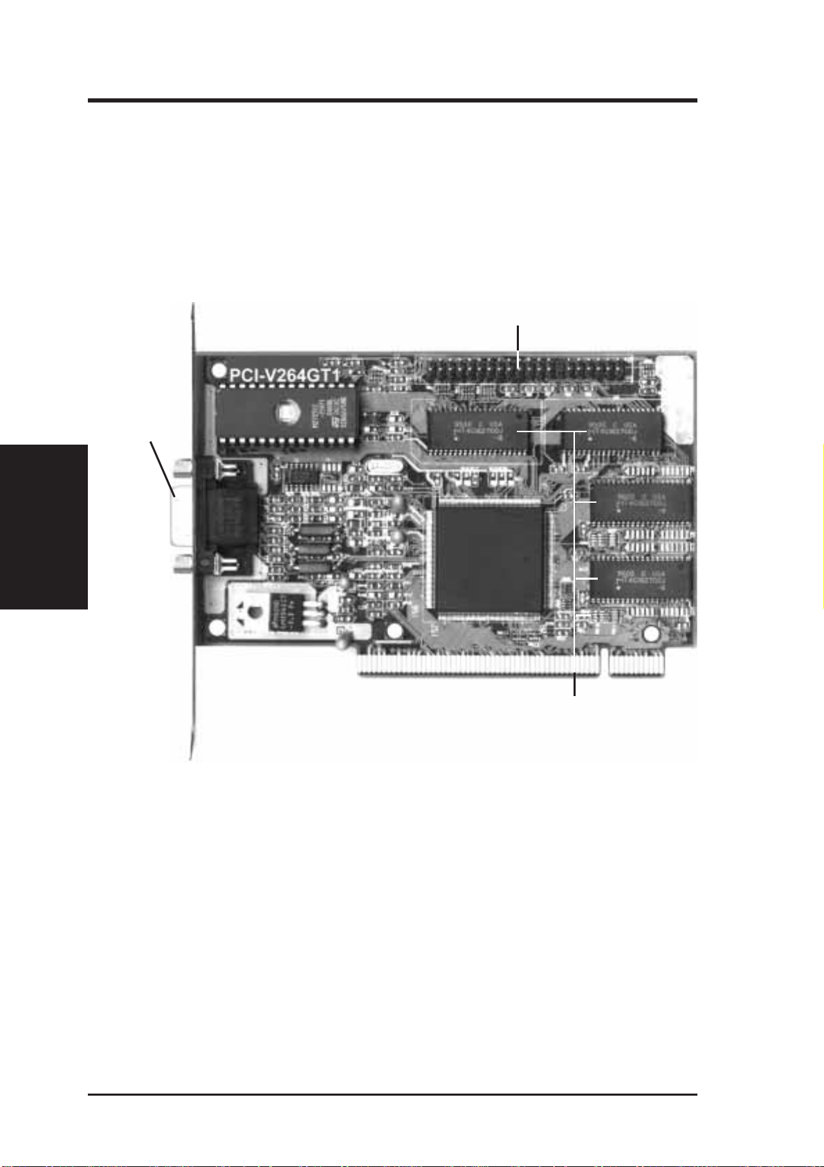
The PCI-V264GT1 is designed to allow you to get up and running as quickly
as possible. This chapter provides you with hardware installation and
memory upgrade instruction. The illustration below shows the layout and
connectors for the PCI-V264GT1 :
PCI-V264GT1 Layout and Connectors.
Monitor
Connector
(Card Layout)
3. Installation
3. Installation
AMC Connector for
ASUS TV-T uner Card
Four Onboard 512KB
EDO DRAM (2MB total)
6
ASUS PCI-V264GT1 User's Manual
Page 13

3. Installation
Jumpers
For some older motherboards, using this card may not allow the system to
boot without setting the card to SP ARSE I/O mode. If your system does not
boot-up, try setting the following jumper to Sparse I/O as illustrated, otherwise leave on default.
I/O Decode Method JP1
Block I/O [Open] (Default)
Sparse I/O [Short]
JP1
Block I/O (Default) Sparse I/O
I/O Decode Method (Block or Sparse)
JP1
Installing the PCI-V264GT1:
1. Unplug all electrical cords on your computer.
2. Remove the screws for the back of the system unit cover.
3. Remove the system unit cover.
4. Locate an available (unused) expansion slot.
5. Remove the computer case's slot cover. Save the screw to anchor the
PCI-V264GT1 mounting bracket later.
6. Ground yourself to an antistatic mat or other grounded source.
7. Pick up the board (still in its sleeve) by grasping the edge bracket with
one hand. Avoiding pressing on board components.
3. Installation
(Jumper/Install)
8. Remove the plastic sleeve.
9. Insert the board into the PCI expansion slot. Press it firmly to ensure
that the board is fully seated. Anchor the board's mounting bracket
using the screw you set aside previously.
10.Replace the cover on the system unit.
11.Connect your analog VGA monitor to the PCI-V264GT1 15-pin VGA
connector, and fasten the retaining screws (if any).
ASUS PCI-V264GT1 User's Manual
7
Page 14

Configuring the Hardware
All new cards are configured to basic VGA (640X480) parameters to ensure
successful initial operation with most systems. The VGA Driver Installation outlines the required steps for configuring your card so that you will get
the full range of resolutions and refresh rates that your monitor can support,
and enhanced drivers for your applications.
NOTES:
• The monitor must be turned on before you apply power to the com-
(Configuration)
3. Installation
• Run the mach64 INST ALL program and select SYSTEM INFORMA-
• For Windows 95, run Setup.Exe in the Windows 95 Diskette.
• For OS/2, see installation for IBM OS/2 2.1, WARP.
• For WindowsNT, see installation for Microsoft WindowsNT 3.x.
• If Windows3.1x is running, do not run the INSTALL program in a full-
• MPEG Software - V ideo for W indows must be installed before MPEG
• Online help for driver installations are provided for all enhanced driv-
3. Installation
puter system. This allows the accelerator card to read Monitor Type
information (plus Resolutions, Refresh Rates and Timings information if the monitor is VESA DDC1/2B compatible) from the monitor
during power-up for proper operation.
If no monitor information is detected, the accelerator card will default
to support color VGA.
TION to check for possible conflicts. Ports used by this card are listed
in Appendix B.
screen DOS shell. Quit Windows and run from the DOS prompt.
software can be installed. Please make sure that you W indows can run
.AVI extensions before installing the Drivers for Windows. You can
find this software in program directories such as "RUNTIME" or
"PLAYER" along with most CD titles that use .AVI extensions.
ers W indows, OS/2, AutoCAD, MicroStation, and VESA BIOS Extension support.
8
ASUS PCI-V264GT1 User's Manual
Page 15

3. Installation
Installation Drivers
The installation disks have been bundled onto a CD for your convenience.
The following are the driver names and location that you may be dealing
with during the installation process. Each directory has its own README
which provides additional information about the drivers.
DIRECTORIES PROGRAM
(ROOT) README.COM (Directory List)
\VIDEO video drivers for various English operating systems
• DRIVERS INSTALL.EXE
video drivers for DOS, Win31, OS/2, Utility, MPEG
• WIN95 [install from Win95]
•• MPEG95 software MPEG for Win95
•• WIN95 video driver for Win95
• WINNT [install from WinNT]
•• NT351 video driver for WinNT Ver. 3.51
•• NT35 video driver for WinNT Ver 3.50
• VIDEO [install from Win3.1 or Win95]
•• VFW1.1E SETUP.EXE
Video for Windows - video player for Win3.1
\JAPANESE
\VIDEO video driver for Japanese systems
•DRIVERS
••DISK1 INST ALL.EXE
OS2INST.EXE
Japanese video drivers for DOS, Win3.1,
& software MPEG, OS/2, Utility
••DISK2 Japanese video drivers for DOS, Win3.1,
& software MPEG, OS/2, Utility
••DISK3 Japanese video drivers for DOS, Win3.1,
& software MPEG, OS/2, Utility
•WIN95 Japanese Win95 Driver
•PLAYER1 Video player for Win3.1 & Win95
•PLAYER2 Video player for Win3.1 & Win95
\ITALIAN
\VIDEO video driver for Italian systems
••DISK1 INSTALL.EXE
OS2INST.EXE
Italian video for DOS, Win3.1, software MPEG, OS/2, Utility
••DISK2 Italian video for DOS, Win3.1, software MPEG, OS/2, Utility
••DISK3 Italian video for DOS, Win3.1, software MPEG, OS/2, Utility
3. Installation
(Software Drivers)
\DISKS Individual installation disks for the above drives (Y ou may copy
\PLA YER1 to 1.44MB 3.5" floppy disks if necessary)
\PLAYER2
\VIDEO
ASUS PCI-V264GT1 User's Manual
9
Page 16

Viewing Readme First
A general README file containing installation, configuration, and support
details which were not available when this User's Guide was prepared and
additional product information is provided on the installation CD. Please
view this file before proceeding with the installation. Insert the CD into the
CD ROM drive and type: D: <Enter> (for example).
IMPORTANT: This manual may make references to both CD's and
floppy disks because original installation floppy disks have been stored
on one installation CD. You may copy each directory back onto 1.44MB
3.5" floppy diskettes if you need to. Please use the appropriate drive
letter and path where you will be installing from.
(Important Notes)
3. Installation
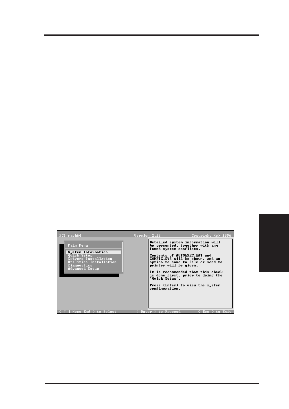
This INSTALL program is used to check the system for possible conflicts,
to set monitor type, to install enhanced display drivers and utilities, to run
card diagnostics, and to customize hardware parameters for maximum performance.
3. Installation
Card configuration is based on multiple choices from screen menus. Where
possible, your selections will be automatically checked by the program for
compatibility, thus ensuring conflict-free operation. Checking is started by
selecting SYSTEM INFORMATION in the Main Menu.
NOTE: Driver installation and card setup functions are provided in the
Main Menu. This menu is the starting point for installing mach64 enhanced
drivers and utilities, and for accessing configuration and testing functions
which help you complete the installation. The INFOBOX (located next to
the Main Menu) provides in-depth information on the currently selected
menu item.
10
ASUS PCI-V264GT1 User's Manual
Page 17
4. VGA Driver Installation
1. Utilities Installation
Select Utilities Installation from the Main Menu to copy mach64 utilities
and INSTALL program to your hard drive. We recommend that you accept
all default paths suggested during the installation. All references to running
INSTALL in later section procedures will be made from
C:\MACH64\INSTALL.EXE after the Utilities have been installed for the
first time from D:\VIDEO\WIN31\INSTALL.EXE.
NOTE: Video for Windows is now provided on this Installation CD.
Install the program first from Windows or DOS inorder to install the
MPEG drivers instructed in this section.
Procedures
1. Turn on the monitor, then the computer. If an error appears, recheck
the installation of your card, then see Appendix A for diagnostics and
troubleshooting information.
2. Insert the CD and type:
D: <ENTER>
CD VIDEO <ENTER>
CD DRIVERS <ENTER>
INSTALL <ENTER>
You will see the main menu as follows:
3. Choose Utilities Installation and press <Enter>.
4. Press <Enter> for the default path when you are prompted.
5. After the installation is completed, you will be prompted to allow
changes to your autoexec.bat file. Enter <Y> to accept changes.
ASUS PCI-V264GT1 User's Manual
4. VGA Driver
(Utilities Installation)
11
Page 18

4. VGA Driver Installation
Utility Installation
6. From DOS prompt C:\> type:
CD MACH64 <Enter>
INSTALL
(System Information)
4. VGA Driver
7. Follow the instructions for Quick Installation as follows:
2. Select System Information
The program will check the system for possible conflicts with the card, and
display both the card and system configurations in the INFO BOX. In case
of a conflict, it will issue a warning and suggest possible corrective actions.
Y our PCI-V264GT1 is PCI Plug-and-Play compatible: your system will automatically allocate system resources and resolve possible conflicts between
your Plug-and-Play compatible mach64 accelerator card and other expansion cards.
12
ASUS PCI-V264GT1 User's Manual
Page 19

4. VGA Driver Installation
System Information
3. Select Quick Setup.
Select Quick Setup to configure the accelerator card to work with your monitor . As you highlight each monitor , the display specifications for that monitor type are listed in the INFO BOX. Proper monitor selection is necessary
for correct resolution and refresh rate operation. You have four options to
choose a correct Monitor Type.
Selecting Your Monitor Type
Factory Default
Apple...
IBM...
MIT...
NEC...
VESA-Std...
Generic...
Read VDIF...
Custom...
Select Read VDIF... If you have a VDIF file for your monitor and wish to
use its parameters to automatically configure the mach64. Additional VDIF
details are provided later in this chapter, in the section: VDIF Files
(Quick Setup)
4. VGA Driver
Select Custom... if none of the above applies to you, or you wish to manually configure the settings. Please refer to the information provided later in
this chapter in the section: Custom Configuration
ASUS PCI-V264GT1 User's Manual
13
Page 20

4. VGA Driver Installation
Notes On Refresh Rates:
• A higher refresh rate reduces screen flicker, and therefore reduces eye
strain. Not all refresh rates are supported at all color depths. Consult
Appendix C, Video Mode Table for details.
• The resolution used by your software application is independent of the
refresh rate. Resolution depends on the installed software driver and
selected display mode. The and the color depth defined by the driver.
VDIF Files
VDIF files are VESA Display Information Format files. They contain all
the necessary configuration parameters for getting optimal resolution and
refresh rate operation from the specified monitor. Consult your monitor
manufacturer for availability of VDIF files.
If you have a VDIF file for your monitor , select it. The INSTALL program
will read the VDIF file and automatically configure the card to properly
work with your monitor.
4. VGA Driver
(VDIF Files)
Procedure:
1. Start the INSTALL program.
2. Select Quick Setup and press <Enter>.
3. Insert into a floppy drive the disk containing the VDIF file.
4. Select READ VDIF... and press <Enter>.
5. Type in the location of the VDIF file (typically A: or B:). INSTALL
will read the file and configure the card to support your monitor according to the VDIF specification.
Custom Configuration
If your monitor is not listed in the Monitor Selection Menu, or you are not
using DDC or VDIF, you can set up display modes, i.e., resolutions and
refresh rates, on the card using the Custom... option. This option is useful
even if you had selected a monitor from the list. For example, you can modify
the screen centering or refresh rate on one resolution, and not change the
other resolutions.
14
ASUS PCI-V264GT1 User's Manual
Page 21

4. VGA Driver Installation
Procedure:
1. Start the INSTALL program.
2. Select Quick Setup and press <Enter>.
3. Select Custom... and press <Enter>.
4. Pick a resolution, then a refresh rate. You will see a box outline.
WARNING:
• An incorrect Monitor T ype setting may damage your monitor. Review
your monitor specifications before making a selection from the Monitor Selection Menu.
• Do not exceed the monitor specifications. Using a refresh rate (i.e.,
vertical frequency) that is higher than specified may damage your monitor. The manufacturer will not be liable for any damage caused by incorrect settings. Consult your monitor manual to determine the highest
refresh rate for each resolution that your monitor supports.
• A scrambled screen indicates your monitor is not capable of the selected display mode. In which case, you should immediately press
<Esc> to exit.
TIP: If the monitor produces a scrambled display, try a lower refresh
rate. If it is already at the lowest refr esh rate, set that r esolution to Not
Supported.”
5. Adjust the size and position of the box outline. Press <Enter> to accept.
6. Repeat steps 2 and 3 until you are satisfied with the box outline for all
the resolutions. When finished, remember to exit and save the settings.
4. VGA Driver
(Custom Config)
ASUS PCI-V264GT1 User's Manual
15
Page 22

4. VGA Driver Installation
4. Select Drivers Installation.
The next step is to install the Video drivers for the applications you will be
using by the following procedures:
1. Select Drivers Installation and press <Enter>
2. Select the Application name such as Microsoft Windows <Enter>
3. Insert the installation CD and enter "D" when it ask what drive you
will be installing from and press <Enter>.
Installing V ideo Driver for Micr osoft Windows
(Drivers Installation)
4. VGA Driver
4. The Windows Enhanced Driver menu pops up giving the options:
Choose Install Windows 3.1 driver and press <Enter>
5. Two installation messages appears which you can press <Enter> to
continue after reading. Another menu pops up giving you the option of
installing:
Choose the first option and press <Enter>
IMPORTANT: Software MPEG r equires the installation of Video for Windows. The following message appears if V ideo for W indows is not detected:
Install Windows 3.1 driver
Uninstall Windows 3.1 driver
Read Installation Notes
Display driver + Software MPEG
Display drivers only
16
ASUS PCI-V264GT1 User's Manual
Page 23

4. VGA Driver Installation
Video for Windows not detected. Unable to install the Software
MPEG drivers, however, the Windows drivers can be installed.
Do you want to continue (Y/N)?
6. If this message appears, go ahead and press "Y" to continue but you
must install Video for Windows and then reinstall this Drivers section
if you wish to have the ATI Player features in the ATI Desktop Control
Panel.
7. If Video for Windows is detected, a message will appearing that:
ATI software Mpeg playback drivers have been Installed
5. Diagnostics
Select Diagnostics from the Main Menu to test the various operations and
circuitry of the accelerator card. The diagnostics screen can be displayed at
any supported resolution and color depth for testing. These tests support
mouse and keyboard operations. Directions are displayed on the screen.
Errors found by testing are discussed in Error Codes and Messages in Appendix A.
6. Advanced Setup
If you have an ISA mach64 accelerator card and wish to fine tune its settings for your monitor and system type, select Advanced Setup from the
Main Menu. On-screen context sensitive help is displayed as you highlight
each Advanced Menu item.
WARNING:
• The Advanced Configuration option allows you to use certain features
that may add additional performance to your card. However these options may not be compatible with your system.
• If problems appear after an advanced option is changed, returning the
card to factory defaults will rectify the situation.
Factory Defaults
The card can be reset to factory defaults by pressing <Shift>+<F7>.
Saving Your Configuration
4. VGA Driver
(Diagnostics/Advance)
Once you have finished configuring the necessary parameters described
above, save them by pressing <F10>.
ASUS PCI-V264GT1 User's Manual
17
Page 24

4. VGA Driver Installation
(Defaults / Saving)
4. VGA Driver
18
ASUS PCI-V264GT1 User's Manual
Page 25

5. Enhanced Drivers
Latest Driver Information
A README file is provided for each application driver in the mach64 installation disks. These files summarize the latest product revisions, and contain directions for installation and use of enhanced drivers. To read the latest driver information, select Drivers Installation from the Main Menu, pick
the appropriate application from the list, and select Read Installation Notes.
For added convenience, after the mach64 drivers have been installed, you
can load and print the README files in the directory of the software application using any word processor.
Installing Drivers
Applications use device drivers to display data on the screen. The mach64
accelerator supports IBM standard VGA and VESA drivers that normally
come with most major software packages. ATI supplies mach64 drivers that
give you more screen resolutions and color depths than standard device
drivers.
In order to fully utilize the enhanced speed, resolution, color depth, and
other features of this card, you should use the supplied mach64 drivers.
NOTE:
• To conserve hard disk space, install only the drivers you use.
• You may require your application software disks during driver installation.
Un-Installing Drivers
This installation program allows you to effortlessly un-install mach64 drivers for W indows and OS/2, and return your application or operating system
environment to VGA support. This feature is available for W indows 3.1 and
OS/2 presentation manager. Details are given in the respective sections.
(Drivers Information)
5. Enhanced Drivers
ASUS PCI-V264GT1 User's Manual
19
Page 26

5. Enhanced Drivers
Microsoft Windows 95
Introduction
The Windows 95 mach64 enhanced display driver is a Windows 95 mini
driver. It is installed and configured using the standard Windows 95 configuration utilities. If you install the PCI-V264GT1 after W indows 95 have
been installed, Windows 95 Plug and Play manager will detect that the
PCI-V264GT1 is different from what was installed previously. Windows
will give you the following message during W indows 95 startup: "The disk
labeled 'Mach 64 Windows 95' is now required. The disk is provided by
your computer manufacturer. Click OK to continue." If you click cancel,
then you must manually change the video driver manually as described in
the following:
Installation
1. Insert the installation CD into the CD-ROM drive.
2. Click the Start button on the lower left of the screen.
3. Click browse to find \video\win95\setup.exe
4. Click the 'Ok' button.
5. Carefully follow the instructions displayed in the help.
6. When the "Install from Disk" window appear, use 'Browse' to find
\video\win95\win95\macxw4.inf
7. Click 'OK' button twice
8. Change the monitor type if necessary.
9. Click 'Close' button.
10.Click 'Apply' button.
11.A message will appear "You must restart your computer before new
settings will take effect. Do you want to restart your computer now?"
Click the 'Yes' button to continue.
5. Enhanced Drivers
(Windows 95)
IMPORTANT: The Adapter Type should be "ATI Mach64 PCI (macxw4)
(DirectDraw)" as loaded from the installation CD. Using the ATI Graphics
Pro Turbo PCI (mach64) as included in the Windows 95 software will not
give the advanced features in the Display Properties.
Windows 95 mach64 enhanced display driver problems
The W indows 95 mach64 enhanced display driver is capable of using monitor timing data contained within W indows 95. This data is selected by configuring a monitor type at Windows 95 installation time or via the "Settings" page of the display properties sheet.
20
ASUS PCI-V264GT1 User's Manual
Page 27

5. Enhanced Drivers
The W indows 95 mach64 enhanced display driver may incorrectly interpret
Windows 95 monitor timing data for some older monitors which require
interlaced modes. This may cause some options to be disabled. A solution
to this problem is to select one of the "(Standard monitor types)" available
via the settings page of the display properties sheet.
If you change the selected monitor type via the "Settings" page of the display properties sheet the new timing data may not take effect until after
restarting W indows 95. A solution to this problem is to always restart W indows 95 after changing the monitor type.
In Windows 95, display drivers can be installed via the "Add New Hardware" wizard. This is not recommended because when the Windows 95
mach64 enhanced display driver is installed via the "Add New Hardware"
wizard the "Settings" page does not get installed into the mach64 display
adapter property sheet.
Windows 95 property page problems
While adjusting monitor settings in the Adjustment page of the Display Properties sheet, your monitor could become unreadable. If this occurs, press the
ESC key to return to your previous monitor settings.
Microsoft Windows NT 3.5 / 3.51
The mach64 driver for Windows NT is shipped with Windows NT. Before
installing the mach64 driver, you must have installed W indows NT and selected VGA display. After driver installation, you may view the
README.NT file for more details.
Installation Procedure:
1. Run the Windows NT Setup program located in the Program Manager
Main window. Select Change System Settings from the Options
pulldown menu.
2. Specify the location of the ATI driver.
3. Select Other, and supply the Setup program with the location of the NT
files, for example, D:\VIDEO\WINNT\NT35 (or NT351). Insert the
installation CD and press <Enter>. The program will install the ATI
driver.
4. Restart Windows NT after completion.
(Windows NT)
5. Enhanced Drivers
ASUS PCI-V264GT1 User's Manual
21
Page 28

De-Installation Procedure:
You may de-install the mach64 driver for Windows NT using either of the
steps shown here:
1. In the WINNT\SYSTEM32\DRIVERS directory , rename the ATI.SYS
file, for example, to ATI.ATI. When you restart Windows NT, it will
not find ATI.SYS, and boot up in VGA.
2. Run the Windows NT Setup program and select a non-ATI driver, for
example, a VGA-Compatible driver . When you restart Windows NT, it
will boot up with the non-ATI driver you just selected.
AutoCAD 386 R10, R11, R12, R13
Installation Procedure:
1. Run AutoCAD386 (protected mode) to ensure that it is properly installed on your system. Note the directory location of the AutoCAD
program files before you start the mach64 installation program. You
will need this information later.
2. Run the mach64 installation program and select Drivers Installation
from the Main Menu.
3. From the list of applications, select AutoCAD. When asked for the
source drive and directory, type in the information and insert the requested diskettes. When the menu appears, select Read Installation
Notes for help and tips on the installation.
4. Follow instructions on the screen to install the DLX press driver.
5. When driver installation is completed, exit the installation program.
Refer to the README.DLD file that has been copied into your
AutoCAD directory for instructions and driver configuration details.
6. Run ADIACAD.BAT to set the necessary driver parameters in the DOS
5. Enhanced Drivers
environment as follows: ADIACAD <Enter>
5. Enhanced Drivers
(AutoCAD)
22
ADIACAD.BAT was created by the mach64 installation program for your
convenience. The parameters it sets must be in the DOS environment before you start AutoCAD.
Tip: If you are already using a batch file to start AutoCAD, consider adding
the contents of ADIACAD to your batch file.
7. Start AutoCAD and reconfigure AutoCAD to use the new enhanced
display list driver . Please refer to your AutoCAD manuals for information on how to select/change a video driver.
ASUS PCI-V264GT1 User's Manual
Page 29

5. Enhanced Drivers
NOTE: The PCI-V264GT1 accelerator hardware must be correctly configured before attempting driver installation. If necessary, return to Configuring the Hardware for information.
IBM OS/2 2.1, WARP
Installation Procedure:
1. Start OS/2. Ensure that it is using the V ideo Graphics Array driver and
that no other OS/2, DOS, or Windows applications are running.
2. Open an OS/2 full-screen command prompt.
3. Insert the installation CD into the CD-ROM drive.
4. Type the following if D: is your CD-ROM:
D: <Enter>
CD VIDEO\WIN31
OS2INST <Enter>
5. Select Install Device Drivers from the Main Menu.
6. Select IBM OS/2 from the list of applications.
7. Select Read Installation Notes for help and tips. Otherwise, select the
Install option to copy the mach64 driver and related files to
C:\MACH_OS2, the default directory.
8. Open an OS/2 Window or OS/2 full-screen command prompt.
9. Type: DSPINSTL <Enter>.
10.When the Display Driver Install panel appears, select Primary Display .
Choose OK to bring up the driver selection list.
11. Select ATI mach64 (Enhanced) from the list. Choose OK.
12. When the source directory panel appears, choose CHANGE and specify
the location of the mach64 driver (C:\MACH_OS2).
13. Select SET, then INSTALL.
14. After the driver is installed, do an OS/2 shut down.
NOTE: If an existing OS/2 driver resolution (set for another card) is not
supported by the mach64 as configured, the OS/2 display will revert to VGA
(640x480).
ASUS PCI-V264GT1 User's Manual
(IBM OS/2)
5. Enhanced Drivers
23
Page 30

5. Enhanced Drivers
NOTE: In the OS/2 driver setup, you can choose only those resolutions
that are supported by the mach64, determined by the Monitor Type, and
resolutions you had configured using the ATI INSTALL program. For selection and configuration details, please refer to "Selecting Your Monitor
Type."
15. Re-start OS/2. It will default to 640x480 in 256 colors. T o change screen
resolution and/or color depth, perform the following steps:
a) Open the OS/2 System folder.
b) Open the System Setup folder.
c) Open the System object.
d) Select Screen tab in the System-Settings notebook.
e) Select a desired resolution and color depth from the list.
f) Close the System-Settings notebook.
g) Do an OS/2 shutdown, then restart OS/2.
16.Refer to the README.OS2 file in the C:\MACH_OS2 directory for
mach64 configuration details.
De-Installation Procedure: — OS/2 2.1
1. Open an OS/2 window or OS/2 full-screen command prompt.
2. Type: DSPINSTL <Enter>
3. When the Display Driver Install panel appears, select Primary Display
and choose OK to bring up the driver selection list.
4. Select Video Graphics Array (VGA) from the list. When prompted,
insert the requested IBM OS/2 Display Driver disk into the drive and
specify the VGA driver source directory.
5. Select INSTALL.
6. After the driver is installed, do an OS/2 shutdown.
(De-Installation OS/2)
5. Enhanced Drivers
Continue with the following steps if you wish to remove mach64 files
from your hard disk.
7. Restart OS/2.
8. Open an OS/2 full-screen command prompt.
9. Insert the mach64 installation disk in the floppy drive and type:
A: <Enter> (For drive B, substitute B: for A:)
OS2INST <Enter>
24
10.Select Install Device Drivers from the Main Menu.
11.Select IBM OS/2 from the list of applications.
12. Select UN-INSTALL OS/2 Driver, then follow instructions on the
screen.
ASUS PCI-V264GT1 User's Manual
Page 31

5. Enhanced Drivers
De-Installation Procedure: OS/2 WARP
1. Open the OS/2 System folder.
2. Open the System Setup folder and the Selective Install object.
3. Select Primary Display and bring up the Display Driver Install panel.
4. Select the Video Graphics Array (VGA) driver and choose OK. The
OS/2 Setup and Installation panel appears.
5. Select INSTALL.
6. Specify the VGA driver source directory and follow the screen instructions.
7. When the VGA driver is installed, do an OS/2 shutdown.
Continue with the following steps if you wish to remove mach64 files
from your hard disk.
8. Restart OS/2.
9. Open an OS/2 full-screen command prompt.
10.Type: D: <Enter>
CD VIDEO\WIN31
OS2INST <Enter>
11.Select Install Device Drivers from the Main Menu.
12.Select IBM OS/2 from the list of applications.
13.Select UN-INSTALL OS/2 Driver, then follow the
instructions on the screen.
ASUS PCI-V264GT1 User's Manual
25
5. Enhanced Drivers
(De-Installation OS/2)
Page 32

5. Enhanced Drivers
Intergraph MicroStation 4.0, 5.0
Installation Procedure:
1. Ensure that MicroStation is properly installed on your system before
continuing with this procedure.
2. Run the mach64 installation program and select Drivers Installation
from the Main Menu.
3. From the list of applications, select MicroStation. Enter the source drive
and directory information, then insert the disk as prompted. When the
menu appears, select Read Installation Notes for help and tips on the
installation.
4. Follow the instructions on screen to complete the driver installation.
5. When driver installation is completed, press <Esc> to exit.
6. Refer to the README.USD file that has been copied into your
MicroStation directory for instructions and driver configuration details.
VESA BIOS Extension
The VESA BIOS Extension (VBE) feature is provided by a DOS TSR program called M64VBE.COM. This program supports software running on
VESA modes using the unique mach64 features, beyond those provided by
standard VGA hardware. If your software and/or games conform to the VBE
standard, you should load M64VBE.COM first.
This VBE utility is located on installation disk #1. It is also copied to the
mach64 directory during utilities installation. To load this utility, go to the
directory containing M64VBE.COM and type: M64VBE<Enter>
To display its supported keywords, type M64VBE <Enter>. To unload it,
5. Enhanced Drivers
(MicroStation/VESA)
type M64VBEU <Enter>. (Please refer to your DOS documentation for conditions on unloading TSRs.)
26
ASUS PCI-V264GT1 User's Manual
Page 33

6. Windows Driver Features
Windows 95
T o install the W indows 95 MPEG driver , insert the installation CD and type
C:\VIDEO\WIN95\MPEG95\SETUP .EXE from your "STAR T/RUN". This
will give you "ATI Multimedia" in your Programs group. Click ATI Player
to bring up the ATI Player screen. For Windows 95, skip the following
Windows 3.1x sections and go directly to the ATI Player on page 38.
ATI Desktop Control Panel (Windows 3.1x)
An ATI DeskTop is installed automatically when you install the enhanced
driver for Windows.
(ATI Desktop)
6. Windows Driver
Double click on the icon to display the ATI Desktop Control Panel.
The A TI DeskTop provides a consistent and integrated control. Depending
on what has been installed, your DeskT op may not have the same number of
features as shown above.
Each feature icon in the Mach64 product group shown in this DeskTop is
described on the following pages.
ASUS PCI-V264GT1 User's Manual
27
Page 34

6. Windows Driver Features
6. Windows Driver
(FlexDesk+)
ATI Desktop Features
ATI Logo: Double click this logo to generate a problem report which includes pertinent data on your system and card configuration to help solve
your problem. Have the report ready before contacting your vendor.
Feature Icons: Double click a Feature icon to launch the associated control panel.
Help On: Click this icon, then click any other icon in the product group to
display Help information on the selected item.
Read Me: Click this icon then click a product logo or feature icon to display the readme file on the item.
FlexDesk+
FlexDesk+ Basic Settings
FlexDesk+ is for configuring the operating modes and parameters of the
PCI-V264GT1. The availability of options in FlexDesk+ is dependent on
the card and its hardware configuration. This control panel allows you to
configure Colors (color depth), Screen Size (resolution), Desktop Size (virtual desktop size), Advanced settings and Default parameters (factory settings). A Status Bar at the bottom of the panel displays help information as
you make your selection.
28
ASUS PCI-V264GT1 User's Manual
Page 35

6. Windows Driver Features
FlexDesk+ Provides dynamic screen information feedback as you adjust
the sliders for "Colors", "Screen Size" and "Desktop Size." Any setting not
supported by the card is shown in gray. A slider will always snap to the
nearest supported setting for the current slider combination.
The Sample Color Bar next to the Sample Monitor dynamically shows a
color palette that approximates the Colors setting as you adjust the Colors
slider.
NOTE: If your desired resolution is not available, check your monitor configuration setting in the INSTALL program.
Sliders
Colors: Selects color depths of 256, 32,000, 65000 and 16.7 million col-
ors.
Screen Size: Selects standard screen resolutions of 640x480, 800x600,
1024x768, 1152x864 and 1280x1024.
Desktop Size: Selects virtual desktop sizes of 640x480, 800x600, 1024x768,
1152x864, 1280x1024 and 1536x1280. Desktop size is greater than or equal
to Screen size. The virtual desktop provides expanded work space on your
screen even if your monitor cannot display that resolution. See DeskScan
for details.
(FlexDesk+)
6. Windows Driver
Buttons
Test: Automatically switches our monitor to display the selected mode
without exiting this control panel, for 10 seconds or until the user clicks the
End T est, OK, or Cancel button. All other buttons and sliders are inactive at
this time. To show dynamic color depth changes in this test, the WinSwitch
feature must be enabled before starting the current session of Windows.
Defaults: Returns Screen Size, Colors and Desktop Size sliders to the default positions. When OK is clicked, these changes will be effective.
Advanced...: Opens the Advanced panel. See FlexDesk+ Advanced Settings.
Help: Displays Help information on FlexDesk+.
OK: Exits the FlexDesk+ control panel and effects all new changes.
Cancel: Discards all changes and exits the FlexDesk+ control panel.
ASUS PCI-V264GT1 User's Manual
29
Page 36

6. Windows Driver Features
6. Windows Driver
(FlexDesk+ Adv .)
FILE Menu
Open: Opens an existing Setting file.
Save: Saves the current settings to the active Setting file.
Save As: Saves the current settings to an alternate Setting file which you
can name.
Exit: Exits the FlexDesk+ control panel.
FEATURES Menu
Defaults: Provides same functionality as the push button.
Advanced...: Provides same functionality as the push button.
HELP Menu
Help: Provides same functionality as the push button.
Contents: Displays the Help index.
About...: Displays the product version number and information
FlexDesk+ Advanced Settings
30
ASUS PCI-V264GT1 User's Manual
Page 37

6. Windows Driver Features
Environment
This parameter specifies logical dots per inch (LDPI). Being logical, i.e.,
not physical dots, the effect will differ depending on screen size. Automatic
Mode chooses the optimal environment setting for the selected screen size.
The Small, Large and DTP settings are 96, 120, and 128 LDPI respectively.
256 Color Palette
This selection is only available in 256 color mode. Windows runs faster
when this option is turned off.
On: Allows the application to define color selection in the palette.
Off: Choose colors from a fixed palette.
Dithering Control
Dithering is meshing two colors to produce the illusion of a third. This
selection is only available in 256 color mode with 256 Color Palette on.
(FlexDesk+ Adv .)
6. Windows Driver
On: Provides standard VGA dithering of colors and color selection boxes.
Off: Provides smooth dithering which results in faster performance than
VGA dithering.
Buttons
Help: Displays Help information on FlexDesk+.
OK: Accepts the advanced settings as shown and returns to the FlexDesk+
main panel.
Cancel: Discards all changes and returns to the FlexDesk+ main panel.
ASUS PCI-V264GT1 User's Manual
31
Page 38

6. Windows Driver Features
6. Windows Driver
(DPMS)
DPMS (for Windows)
VESA DPMS-compliant monitors conserve electrical energy by powering
down after a period of inactivity. You can use the DPMS panel (in Windows) to configure the auto-shutdown timing sequence for your DPMScompliant monitor. (The DOS version of DPMS is described in another
section.)
WARNING:
• Monitors that do not support VESA DPMS can be damaged by activation of the DPMS feature.
• Do not use screen saver when DPMS is enabled. The screen saver will
conflict with the DPMS operation.
Procedure:
1. Click the DPMS icon.
2. Highlight the timer boxes one at a time and specify the
values.
3. Turn on DPMS Enabled.
4. Click OK.
Timer Settings
Standby Time: Time value is in minutes, after which Standby mode is
activated if no user activity is detected. Standby is the first level of power
conservation.
Suspend Time: Time value is in minutes, after which Suspend mode is
activated if no user activity is detected. The monitor conserves more energy at this level than at Standby.
32
ASUS PCI-V264GT1 User's Manual
Page 39

6. Windows Driver Features
Off Time
Time value is in minutes, after which Off mode is activated if no service
activity is detected. At this level, energy conservation is the highest.
Buttons
DPMS Enable: DPMS feature is enabled if box is checked.
Defaults: Sets DPMS timers to default values.
Help: Displays Help information on DPMS.
OK: Accepts settings as shown and exits.
Cancel: Discards all changes and exits.
DeskScape
(DeskScape)
6. Windows Driver
NOTE: Press Default to fill in the fields with default keys first.
DeskScape allows more control over your Virtual Desktop using keyboard
keys. For a description of Screen and Desktop, Refer to the Using FlexDesk+
section.
The displayed image on the screen is a "window" showing only a portion of
the entire virtual desktop. The non-displayed portion can be brought into
view by panning. Four keys are assigned to this function, one for each
direction of up, down, left and right. If you are using a mouse, the window
may be panned by moving the mouse cursor to any edge of the window as
well.
ASUS PCI-V264GT1 User's Manual
33
Page 40

6. Windows Driver Features
6. Windows Driver
(Desk Scan)
Zoom In will display a larger image but less of the desktop; Zoom Out has
the opposite effect. What you can zoom is dependent on the relative settings of Screen Size and Desktop Size.
Use this panel to assign the six hot keys to Panning and Zooming functions.
Alphanumeric keys may be assigned in any combination with <AL T>,<Ctrl>
and <Shift>. We recommend that you assign all the keys in one session.
DeskScape Functions
Pan Up: Moves the "window" upward, with a user defined key sequence,
e.g., <Alt>+<Up Arrow>
Pan Left: Moves the "window" to the left, with a user defined key sequence, e.g., <Alt>+<Left Arrow>.
Pan Right: Moves the "window" to the right, with a user defined key sequence, e.g., <Alt>+<Right Arrow>.
Pan Down: Moves the "window" downward, with a user defined key sequence, e.g.. <Alt>+<Down Arrow>
Zoom In: Makes the screen image larger , with a user defined key sequence,
e.g., <Alt>+<Home>. NOTE: The entire desktop can be panned.
Zoom Out: Displays more of the virtual desktop, with a user defined key
sequence, e.g., <Alt>+<End>
Buttons
Defaults: Assigns default keys to DeskScan.
Help: Displays Help information on DeskScan.
OK: Accepts key assignments as shown and exits.
Cancel: Discards all changes and exits.
34
ASUS PCI-V264GT1 User's Manual
Page 41

6. Windows Driver Features
WinSwitch
NOTE: Press Default to fill in the fields with default keys first.
By pressing a user-defined set of keyboard keys WinSwitch can dynami-
cally change screen attributes (i.e., Colors, Screen Size and Desktop Size)
without exiting Windows.
(WinSwitch)
6. Windows Driver
When enabled, W inSwitch is actually operating in 24bpp mode-i.e., all other
color depths and resolutions are emulations. As such, graphics performance
across various color depths will be practically identical to that of 24bpp
(16.7 million colors). Therefore, W inSwitch should be used only when color
depth changes are desired. For maximum performance in 256 or 65,000
color modes, you should disable W inSwitch. FlexDesk+ or DeskScan can
provide the same dynamic screen size or desktop size switching functions.
Configuring the WinSwitch Panel
At the top of the panel is a checkbox labelled WinSwitch Enabled. This
switch must be turned on (checked) to enable WinSwitch, which is primarily a dynamic color switching function. Clicking one of the four radio
buttons (e.g., key 1) will display the slider positions currently associated
with that key.
ASUS PCI-V264GT1 User's Manual
35
Page 42

6. Windows Driver Features
6. Windows Driver
(WinSwitch)
Procedure:
1. Select a radio button. Define the key combination in the field below it.
You must include <Ctrl> or <Alt>.
2. Adjust any or all of the sliders. Slider functions are identical to those
in FlexDesk+.
3. Either enable WinSwitch by checking the WinSwitch Enabled box, or
disable WinSwitch by removing the check mark.
4. Click OK.
Buttons
Key 1: First of four radio buttons labeled key1, key 2, key 3, and key 4. The
slider settings shown are associated with the selected radio button.
Defaults: Restores key combination and slider settings to defaults.
Help: Displays Help information on WinSwitch.
OK: Accepts current settings and exits.
Cancel: Discards all changes and exits.
WinSwitch: Switching function is enabled when the box is
Enabled: Checked; disabled when the box is empty.
Key Combination Fields
Key 1 Field: Keyboard key combinations to be used to activate W inSwitch
are specified in the four key combination fields, associated with Keys 1-4.
Sliders
These sliders provide the same functions as the FlexDesk+ sliders.
Colors: Selects a color depth from one of the supported Colors.
Screen Size: Sets the screen resolution to one of the supported sizes.
Desktop Size: Sets the virtual desktop to one of the supported sizes.
36
ASUS PCI-V264GT1 User's Manual
Page 43

6. Windows Driver Features
Screen Adjustment
This allows the selection of different resolutions supported by your monitor. Select the proper monitor by pressing the "Select Monitor" button and
then choosing from the list of monitors.
6. Windows Driver
(Screen Adjustment)
If your monitor came with a VDIF file then you may insert it into your
floppy drive and press the "Load VDIF" button. The "Custom" button
allows you to select the resolution and refresh rates. You may try out differ ent settings that will optimize your display preferences but too high of a
refresh rate will push your monitor past its specifications. Use the Preview/
Adjust to see the results and allow digital adjustments to the screen. If the
image is distorted you may press <Esc> or wait a few seconds to return to
the original menu without the change.
ASUS PCI-V264GT1 User's Manual
37
Page 44

6. Windows Driver Features
6. Windows Driver
(ATI Player)
Windows 3.1 Adjustment: Windows 95 Adjustment:
ATI Player (Windows 3.1x, Windows 95)
If MPEG drivers are installed, for playing video clips, the ATI Player icon
will appear in the DeskT op. Double click on this icon to bring up the Video
Screen as shown here:
Always on Top
Inspect
Minimize
Close
38
Play
Continuous Replay
of Selected Files
Full Screen
ASUS PCI-V264GT1 User's Manual
Volume Control
Open Files To Play
Settings
Page 45

6. Windows Driver Features
The question mark on top right of the Video Screen allows inspection into
each button on the control panel. Click on the "?" then on a button that you
would like to know about.
ATI Player Settings
6. Windows Driver
(ATI Player Settings)
The ATI Player settings allow changes in sizing and position of the Video
Screen.
ASUS PCI-V264GT1 User's Manual
39
Page 46

6. Windows Driver Features
6. Windows Driver
(Selecting Files)
Select Files To Play
For MPEG CD's, select the proper drive of the CD ROM and click on the
'Play CD" button. For MPEG files, select the files and click the "Add"
button to add to the play list then click on the "Play" button.
NOTE: The above data is only an example and is not included in the software bundle.
Video Acceleration Performance
Video is very data-intensive. For this reason, there are a number of factors
which will negatively impact playback performance, including the type of
compression used. RLE and V ideo 1 are manageable with most 386 or higher
systems; Indeo supports additional color depth, and is best run on faster 486
(or Pentium) systems.
MVA becomes evident when the video window is stretched, more so at 3x
or 4x zoom, with "Skip video frames if behind" disabled.
Playing Video Clips
Use the Microsoft W indows Media Player to play or insert video clips (i.e.,
files with the .AVI filename extension) into various documents. For details
please refer to the Media Player on-line Help and the Microsoft Windows
3.1 User's Guide.
Sizing Windows
The video clip window can be sized using <Ctrl> and number keys 1 & 2,
providing 1x and 2x zoom respectively.
40
ASUS PCI-V264GT1 User's Manual
Page 47

7. Monitor Power Management
The PCI-V264GT1 supports a VESA power management control specification called DPMS-Display Power Management Signaling. Monitors that
comply with DPMS can provide energy savings up to 80% compared to
non DPMS compliant monitors. This also translates into extended monitor
life.
DPMS control functions are provided for DOS and Windows operations.
This chapter describes the DOS version, a Terminate-and-Stay-Resident
program. TSR means it runs in the background once activated. The Windows version provides control via a W indows type control panel in the ATI
DeskT op.
NOTES:
• Monitors that do not support VESA DPMS can be damaged by activation of the DPMS feature. Check your monitor specifications.
• Do not use screen saver when DPMS is enabled. The screen saver will
conflict with DPMS operation.
DPMS (for DOS)
When you run DPMS for the first time, without parameters, DPMS will set
the Standby, Suspend, and Off timers to default values. If DPMS has been
loaded, running it again without parameters will display the current timer
values, as follows:
Standby timer: 15 minutes
Suspend timer: 30 minutes
off timer: 60 minutes
If you run DPMS with at least one timer parameter, DPMS will set that
value and disable the unspecified timers.
(DPMS for DOS)
7. Monitor Power
DPMS parameters are to be included in the command separated by spaces,
as follows:
DPMS parameter <Enter>
Example:
To set the Standby timer to 5 minutes, and disable the Suspend and Off
timers:
DPMS STBY 5 <Enter>
ASUS PCI-V264GT1 User's Manual
41
Page 48

7. Monitor Power Management
DPMS Parameters
stby x
Places the monitor into Standby mode after x minutes and seconds. For example, x for two minutes and ten seconds is specified as 2:10. Standby is
the first level of power conservation. The monitor is instantly ready if ac-
(DPMS Parameters)
7. Monitor Power
tivity is detected.
susp x
Places the monitor into Suspend mode after x minutes and seconds. The
monitor conserves more energy at this level than at Standby.
off x
Places the monitor into Off mode after x minutes and seconds. The monitor
is at the highest level of energy conservation.
nomouse
Does not detect mouse activity.
quiet
Suppresses DPMS messages.
unload
Un-installs DPMS from system memory.
help
Displays help messages.
42
ASUS PCI-V264GT1 User's Manual
Page 49

A. Troubleshooting
Diagnostics
All installed graphics modes in the mach64 accelerator can be viewed and
tested, by running the INSTALL program from the DOS prompt, or by
running a diagnostics program called M64DIAG.EXE. Do not run it in a
windowed or full-screen DOS box.
In the INST ALL program, select Test Graphics Adapter from the Diagnostics... option of the Main Menu. The Test Graphics Adapter menu has the
following options:
• VGA Tests ...
• Accelerator Tests ...
Any time you suspect there is a problem, especially during installation, run
the above tests. The information provided in this appendix will enable you
to solve most problems.
Troubleshooting
Because a typical computer system consists of many different parts, difficulties may arise from a combination of items, from software or hardware
installation, to monitor compatibility. Listed below are several checks you
can make to help determine what the problem is.
A. Troubleshooting
System Lockup
• If you are using a memory manager such as QEMM or 386MAX you
need to modify the command line in the CONFIG.SYS file so that the
address of the graphics card video BIOS, C000 - C7FF, is excluded.
For example, add "EXCLUDE = C000 - C7FF" to the command line.
• Remove all unnecessary boards.
• Disable shadow RAM.
• Ensure that the board is seated correctly and that the card has been
installed using the proper utilities.
• Try the card in a different system and reset to factory defaults using
the INST ALL program. If the card works in another system, the problem is likely due to incorrect configuration.
(Diagnostics)
A. Troubleshooting
ASUS PCI-V264GT1 User's Manual
43
Page 50

Test Patterns OK; Applications Do Not Sync
Windows Driver Not Installing Properly
AutoCAD Driver Not Installing Properly
A. Troubleshooting
(Error Codes)
Error Codes and Messages
A. Troubleshooting
• The wrong monitor type has been selected. Change the settings in the
INSTALL program.
• Windows must be running in 386 Enhanced Mode. Incompatible
memory managers may prevent Windows from starting in enhanced
mode. If this occurs, remove the offending driver or memory manager .
• If using a 386, ensure that AutoCAD has been configured
for the appropriate ADI driver . The protected mode driver requires extended memory.
Problems and solutions for some common errors found by the test program
are provided for your reference as follows:
Memory aperture test failure or Diagnostics program locks or Reboots
during aperture test
If you receive an error message indicating that the memory aperture location is conflicting with your system memory , restart the INSTALL program
as follows: INSTALL APMAP <Enter>. Now when you enable Memory
Aperture, you must select a location above but not overlapping System
Memory (S), BIOS (B) or Reserved (R) locations. Not applicable for ISA
cards.
Desired resolution is disabled and displayed in gray
A mode displayed in gray means that the BIOS is told this mode is not
available, based on the card configuration. Re-install using custom monitor
selection.
44
ASUS PCI-V264GT1 User's Manual
Page 51

A. Troubleshooting
Menu item is disabled and displayed in gray
The test program has determined that the mode or test is not available under
the current configuration. Aperture tests are not available if the aperture is
disabled, and CR T mode and pixel depth are determined by current installation, DAC type, memory size, and memory type.
Adapter not detected
This message should only occur when a mach64 ASIC is not detected. If
this message occurs and a mach64 board is present, it may indicate an I/O
conflict, conflicts between the Extended Memory Manager (EMM) and the
video ROM. Try removing all other boards from the system and booting
from a plain DOS disk. Try excluding the video BIOS address (C0000C7FFF) from the memory manager. Refer to the documentation furnished
with the memory manager software for information.
Any FIFO test error
The effects of a bad command FIFO should be visible. (e.g., the screen does
not come up, or it displays garbage.)
Quick memory test error
Run Detailed RAM Test to confirm the error and identify the address of the
error .
Detailed memory test error.
Run Detailed RAM T est several times to confirm the error and take notes of
any messages and error codes.
DAC LUT test failure.
An error has occurred while testing the DAC LookUp Table. The problem
should be visible on the top color bar of any 8bpp mode.
ROM checksum error.
An error has been detected in the ROM.
Draw sequence failure.
An error has occurred in the draw engine. If the error is intermittent, it might
indicate a marginal RAM failure. The effects of this failure may not be
immediately apparent.
(Error Codes)
A. Troubleshooting
ASUS PCI-V264GT1 User's Manual
45
Page 52

B. Specifications
System Requirements
PCI motherboard computer system is required
Operating Environments — one of:
• DOS 5.0 or higher or Windows 3.1
• Windows 95
• Windows NT
• OS/2 2.1 or OS/2 Warp
Sync Signals
Separate horizontal and vertical sync at TTL levels.
Video Memory Address
A000 - BFFF plus the memory aperture address enabled through the
INSTALL program.
Video BIOS Address
C000 - C7FF.
Video Port Address
102, 1CE, 1CF, 2E8, 2EC, 2ED, 2EE, 2EF, 3?4, 3?5, 3?8, 3?9, 3?A,
3?B, 3C0, 3C1, 3C2, 3C3, 3C4, 3C5, 3C6, 3C7, 3C8, 3C9, 3CA, 3CC,
3CE, 3CF, 3DC, and all aliases; 46E8.
B. Specifications
(?=B for monochrome, ?=D for color operation)
Video Output Connector
15-pin D shell (Female), IBM standard.
VGA Feature Connector
26-pin header, VGA Out only, VESA standard.
Video interrupt
PCI system auto-configurable.
Power
+5V +/-5%, @ 1.3A typical.
46
ASUS PCI-V264GT1 User's Manual
Page 53

C. Video Mode Tables
When discussing color depth, 8 bits per pixel (8bpp) is the same as 256
colors. Therefore, the relation between bpp and colors is as follows:
• 8bpp = 256 colors.
• 16bpp = 65,000 colors.
• 24bpp = 16.7 million colors.
The PCI-V264GT1 also supports 15bpp (32,000 colors). Any resolution
and refresh settings that support 16bpp will support 15bpp. Please refer to
the mode tables for details.
Referesh Rates
Resolution 1MB 2MB
640 x 480 x 8 100Hz 120Hz
640 x 480 x 16 100Hz 120Hz
640 x 480 x 24 85Hz 90Hz
640 x 480 x 32 N/A 85Hz
800 x 600 x 8 100Hz 100Hz
800 x 600 x 16 75Hz 100Hz
800 x 600 x 24 N/A 60Hz
1024 x 768 x 8 75Hz 100Hz
1024 x 768 x 16 N/A 75Hz
1152 x 864 x 8 80Hz 80Hz
1280 x 1024 x 8 N/A 75Hz
ASUS PCI-V264GT1 User's Manual
C. Video Mode Tables
47
Page 54

48
ASUS PCI-V264GT1 User's Manual
 Loading...