

Asus P7H55, USB3 User Manual

P7H55/USB3
Motherboard

E5833
First Edition (V1)
May 2010
Copyright © 2010 ASUSTeK COMPUTER INC. All Rights Reserved.
No part of this manual, including the products and software described in it, may be reproduced,
transmitted, transcribed, stored in a retrieval system, or translated into any language in any form or by any
means, except documentation kept by the purchaser for backup purposes, without the express written
permission of ASUSTeK COMPUTER INC. (“ASUS”).
Product warranty or service will not be extended if: (1) the product is repaired, modied or altered, unless
such repair, modication of alteration is authorized in writing by ASUS; or (2) the serial number of the
product is defaced or missing.
ASUS PROVIDES THIS MANUAL “AS IS” WITHOUT WARRANTY OF ANY KIND, EITHER EXPRESS
OR IMPLIED, INCLUDING BUT NOT LIMITED TO THE IMPLIED WARRANTIES OR CONDITIONS OF
MERCHANTABILITY OR FITNESS FOR A PARTICULAR PURPOSE. IN NO EVENT SHALL ASUS, ITS
DIRECTORS, OFFICERS, EMPLOYEES OR AGENTS BE LIABLE FOR ANY INDIRECT, SPECIAL,
INCIDENTAL, OR CONSEQUENTIAL DAMAGES (INCLUDING DAMAGES FOR LOSS OF PROFITS,
LOSS OF BUSINESS, LOSS OF USE OR DATA, INTERRUPTION OF BUSINESS AND THE LIKE),
EVEN IF ASUS HAS BEEN ADVISED OF THE POSSIBILITY OF SUCH DAMAGES ARISING FROM ANY
DEFECT OR ERROR IN THIS MANUAL OR PRODUCT.
SPECIFICATIONS AND INFORMATION CONTAINED IN THIS MANUAL ARE FURNISHED FOR
INFORMATIONAL USE ONLY, AND ARE SUBJECT TO CHANGE AT ANY TIME WITHOUT NOTICE,
AND SHOULD NOT BE CONSTRUED AS A COMMITMENT BY ASUS. ASUS ASSUMES NO
RESPONSIBILITY OR LIABILITY FOR ANY ERRORS OR INACCURACIES THAT MAY APPEAR IN THIS
MANUAL, INCLUDING THE PRODUCTS AND SOFTWARE DESCRIBED IN IT.
Products and corporate names appearing in this manual may or may not be registered trademarks or
copyrights of their respective companies, and are used only for identication or explanation and to the
owners’ benet, without intent to infringe.
Offer to Provide Source Code of Certain Software
This product may contain copyrighted software that is licensed under the General Public License (“GPL”)
and under the Lesser General Public License Version (“LGPL”). The GPL and LGPL licensed code in this
product is distributed without any warranty. Copies of these licenses are included in this product.
You may obtain the complete corresponding source code (as dened in the GPL) for the GPL Software,
and/or the complete corresponding source code of the LGPL Software (with the complete machinereadable “work that uses the Library”) for a period of three years after our last shipment of the product
including the GPL Software and/or LGPL Software, which will be no earlier than December 1, 2011, either
(1) for free by downloading it from http://support.asus.com/download;
or
(2) for the cost of reproduction and shipment, which is dependent on the preferred carrier and the location
where you want to have it shipped to, by sending a request to:
ASUSTeK Computer Inc.
Legal Compliance Dept.
15 Li Te Rd.,
Beitou, Taipei 112
Taiwan
In your request please provide the name, model number and version, as stated in the About Box of the
product for which you wish to obtain the corresponding source code and your contact details so that we
can coordinate the terms and cost of shipment with you.
The source code will be distributed WITHOUT ANY WARRANTY and licensed under the same license as
the corresponding binary/object code.
This offer is valid to anyone in receipt of this information.
ASUSTeK is eager to duly provide complete source code as required under various Free Open Source
Software licenses. If however you encounter any problems in obtaining the full corresponding source code
we would be much obliged if you give us a notication to the email address gpl@asus.com, stating the
product and describing the problem (please do NOT send large attachments such as source code archives
etc to this email address).
ii

Contents
Notices ......................................................................................................... vi
Safety information ..................................................................................... vii
About this guide ....................................................................................... viii
P7H55/USB3 specications summary ...................................................... ix
Chapter 1: Product introduction
1.1 Before you proceed ..................................................................... 1-1
1.2 Motherboard overview ................................................................. 1-2
1.2.1 Motherboard layout ......................................................... 1-2
1.2.2 Layout contents ............................................................... 1-2
1.3 Central Processing Unit (CPU) ................................................... 1-3
1.3.1 Installing the CPU ........................................................... 1-3
1.3.2 Installing the CPU heatsink and fan ................................ 1-6
1.3.3 Uninstalling the CPU heatsink and fan ........................... 1-7
1.4 System memory ........................................................................... 1-8
1.4.1 Overview ......................................................................... 1-8
1.4.2 Memory congurations .................................................... 1-9
1.4.3 Installing a DIMM .......................................................... 1-16
1.4.4 Removing a DIMM ........................................................ 1-16
1.5 Expansion slot ............................................................................ 1-17
1.5.1 Installing an expansion card ......................................... 1-17
1.5.2 Conguring an expansion card ..................................... 1-17
1.5.3 PCI slots ........................................................................ 1-17
1.5.4 PCI Express x1 slots ..................................................... 1-17
1.5.5 PCI Express 2.0 x16 slots ............................................. 1-17
1.6 Jumpers ...................................................................................... 1-18
1.7 Onboard switches ...................................................................... 1-19
1.8 Connectors ................................................................................. 1-21
1.8.1 Rear panel connectors .................................................. 1-21
1.8.2 Internal connectors ....................................................... 1-22
1.9 Installing an operating system ................................................. 1-28
1.10 Support DVD information .......................................................... 1-28
1.10.1 Running the support DVD ............................................. 1-28
Chapter 2: BIOS setup
2.1 Managing and updating your BIOS ............................................ 2-1
iii

Contents
2.1.1 ASUS Update .................................................................. 2-1
2.1.2 ASUS EZ Flash 2 ............................................................ 2-2
2.1.3 ASUS CrashFree BIOS 3 utility ...................................... 2-3
2.2 BIOS setup program .................................................................... 2-4
2.3 Main menu .................................................................................... 2-4
2.3.1 SATA 1-6 ......................................................................... 2-5
2.3.2 Storage Conguration ..................................................... 2-6
2.3.3 AHCI Conguration ......................................................... 2-6
2.3.4 System Information ......................................................... 2-7
2.4 Ai Tweaker menu .......................................................................... 2-8
2.4.1 CPU Level Up ................................................................ 2-8
2.4.2 Ai Overclock Tuner ......................................................... 2-9
2.4.3 CPU Ratio Setting .......................................................... 2-9
2.4.4 Intel(R) SpeedStep(TM) Tech ...................................... 2-10
2.4.5 Intel(R) TurboMode Tech .............................................. 2-10
2.4.6 Xtreme Phase Full Power Mode .................................. 2-10
2.4.7 DRAM Frequency ........................................................ 2-10
2.4.8 QPI Frequency ............................................................. 2-10
2.4.9 ASUS/3rd Party UI Priority ............................................ 2-10
2.4.10 OC Tuner .......................................................................2-11
2.4.11 Start auto tuning .............................................................2-11
2.4.12 DRAM Timing Control ...................................................2-11
2.4.13 CPU Differential Amplitude ........................................... 2-13
2.4.14 CPU Clock Skew .......................................................... 2-13
2.4.15 CPU Voltage Mode ....................................................... 2-13
2.4.16 IMC Voltage ................................................................ 2-13
2.4.17 DRAM Voltage ............................................................ 2-13
2.4.18 CPU PLL Voltage ......................................................... 2-14
2.4.19 PCH Voltage ................................................................ 2-14
2.4.20 DRAM DATA REF Voltage on CHA/B .......................... 2-14
2.4.21 Load-Line Calibration ................................................... 2-14
2.4.22 CPU Spread Spectrum ................................................ 2-14
2.4.23 PCIE Spread Spectrum ................................................ 2-14
2.5 Advanced menu ......................................................................... 2-15
2.5.1 CPU Conguration ........................................................ 2-15
iv

Contents
2.5.2 Uncore Conguration .................................................... 2-17
2.5.3 Onboard Device Conguration ...................................... 2-17
2.5.4 USB Conguration ........................................................ 2-17
2.5.5 PCIPnP ......................................................................... 2-18
2.5.6 Intel VT-d Conguration ............................................... 2-18
2.6 Power menu ................................................................................ 2-19
2.6.1 Suspend Mode ............................................................. 2-19
2.6.2 Repost Video on S3 Resume ........................................ 2-19
2.6.3 ACPI 2.0 Support ......................................................... 2-19
2.6.4 ACPI APIC Support ...................................................... 2-19
2.6.5 EuP Ready ................................................................... 2-19
2.6.6 APM Conguration ........................................................ 2-20
2.6.7 Hardware Monitor ......................................................... 2-21
2.7 Boot menu .................................................................................. 2-22
2.7.1 Boot Device Priority ...................................................... 2-22
2.7.2 Boot Settings Conguration .......................................... 2-22
2.7.3 Security ......................................................................... 2-23
2.8 Tools menu ................................................................................. 2-25
2.8.1 ASUS O.C. Prole ......................................................... 2-25
2.8.2 AI NET 2........................................................................ 2-25
2.8.3 ASUS EZ Flash 2 .......................................................... 2-26
2.8.4 Express Gate ............................................................... 2-26
2.9 Exit menu .................................................................................... 2-27
v
Notices
Federal Communications Commission Statement
This device complies with Part 15 of the FCC Rules. Operation is subject to the following two
conditions:
•
This device may not cause harmful interference, and
•
This device must accept any interference received including interference that may cause
undesired operation.
This equipment has been tested and found to comply with the limits for a Class B digital
device, pursuant to Part 15 of the FCC Rules. These limits are designed to provide
reasonable protection against harmful interference in a residential installation. This
equipment generates, uses and can radiate radio frequency energy and, if not installed
and used in accordance with manufacturer’s instructions, may cause harmful interference
to radio communications. However, there is no guarantee that interference will not occur
in a particular installation. If this equipment does cause harmful interference to radio or
television reception, which can be determined by turning the equipment off and on, the user
is encouraged to try to correct the interference by one or more of the following measures:
•
Reorient or relocate the receiving antenna.
•
Increase the separation between the equipment and receiver.
•
Connect the equipment to an outlet on a circuit different from that to which the receiver is
connected.
•
Consult the dealer or an experienced radio/TV technician for help.
The use of shielded cables for connection of the monitor to the graphics card is required
to assure compliance with FCC regulations. Changes or modications to this unit not
expressly approved by the party responsible for compliance could void the user’s authority
to operate this equipment.
Canadian Department of Communications Statement
This digital apparatus does not exceed the Class B limits for radio noise emissions from
digital apparatus set out in the Radio Interference Regulations of the Canadian Department
of Communications.
This class B digital apparatus complies with Canadian ICES-003.
REACH
Complying with the REACH (Registration, Evaluation, Authorisation, and Restriction of
Chemicals) regulatory framework, we published the chemical substances in our products at
ASUS REACH website at http://green.asus.com/english/REACH.htm.
DO NOT throw the motherboard in municipal waste. This product has been designed to
enable proper reuse of parts and recycling. This symbol of the crossed out wheeled bin
indicates that the product (electrical and electronic equipment) should not be placed in
municipal waste. Check local regulations for disposal of electronic products.
DO NOT throw the mercury-containing button cell battery in municipal waste. This symbol
of the crossed out wheeled bin indicates that the battery should not be placed in municipal
waste.
vi
Safety information
Electrical safety
•
To prevent electrical shock hazard, disconnect the power cable from the electrical outlet
before relocating the system.
•
When adding or removing devices to or from the system, ensure that the power cables
for the devices are unplugged before the signal cables are connected. If possible,
disconnect all power cables from the existing system before you add a device.
•
Before connecting or removing signal cables from the motherboard, ensure that all
power cables are unplugged.
•
Seek professional assistance before using an adpater or extension cord. These devices
could interrupt the grounding circuit.
• Make sure that your power supply is set to the correct voltage in your area. If you are
not sure about the voltage of the electrical outlet you are using, contact your local power
company.
•
If the power supply is broken, do not try to x it by yourself. Contact a qualied service
technician or your retailer.
•
The optical S/PDIF is an optional component (may or may not be included in your
motherboard) and is dened as a CLASS 1 LASER PRODUCT.
INVISIBLE LASER RADIATION, AVOID EXPOSURE TO BEAM.
• Never dispose of the battery in re. It could explode and release harmful substances into
the environment.
• Never dispose of the battery with your regular household waste. Take it to a hazardous
material collection point.
• Never replace the battery with an incorrect battery type.
• RISK OF EXPLOSION IF BATTERY IS REPLACED BY AN INCORRECT TYPE.
• DISPOSE OF USED BATTERIES ACCORDING TO THE ABOVE BATTERY-RELATED
INSTRUCTIONS.
Operation safety
•
Before installing the motherboard and adding devices on it, carefully read all the manuals
that came with the package.
•
Before using the product, make sure all cables are correctly connected and the power
cables are not damaged. If you detect any damage, contact your dealer immediately.
•
To avoid short circuits, keep paper clips, screws, and staples away from connectors,
slots, sockets and circuitry.
•
Avoid dust, humidity, and temperature extremes. Do not place the product in any area
where it may become wet.
•
Place the product on a stable surface.
•
If you encounter technical problems with the product, contact a qualied service
technician or your retailer.
vii

About this guide
This user guide contains the information you need when installing and conguring the
motherboard.
How this guide is organized
This guide contains the following parts:
• Chapter 1: Product introduction
This chapter describes the features of the motherboard and the new technology it
supports.
• Chapter 2: BIOS information
This chapter tells how to change system settings through the BIOS Setup menus.
Detailed descriptions of the BIOS parameters are also provided.
Where to nd more information
Refer to the following sources for additional information and for product and software
updates.
1. ASUS websites
The ASUS website provides updated information on ASUS hardware and software
products. Refer to the ASUS contact information.
2. Optional documentation
Your product package may include optional documentation, such as warranty yers,
that may have been added by your dealer. These documents are not part of the
standard package.
Conventions used in this guide
To make sure that you perform certain tasks properly, take note of the following symbols used
throughout this manual.
DANGER/WARNING: Information to prevent injury to yourself when trying to
complete a task.
CAUTION: Information to prevent damage to the components when trying to
complete a task.
IMPORTANT: Instructions that you MUST follow to complete a task.
NOTE: Tips and additional information to help you complete a task.
Typography
Bold text Indicates a menu or an item to select.
Italics
Used to emphasize a word or a phrase.
<Key> Keys enclosed in the less-than and greater-than sign means
that you must press the enclosed key.
Example: <Enter> means that you must press the Enter or
Return key.
<Key1>+<Key2>+<Key3> If you must press two or more keys simultaneously, the key
names are linked with a plus sign (+).
Example: <Ctrl>+<Alt>+<D>
viii

P7H55/USB3 specications summary
CPU LGA1156 socket for Intel® Core™ i7 / Core™ i5 /
Chipset Intel® H55 Express Chipset
Memory 4 x DIMM, max. 16GB, DDR3 2200(O.C.)* / 2000 / 1866 /
Expansion Slots 1 x PCI Express 2.0 x16 slot (blue)
Multi-GPU support Supports ATI® Quad-GPU CrossFireX™ Technology
Storage Intel® H55 Express Chipset:
LAN Realtek® 8112L Gigabit LAN controller featuring AI NET2
USB 10 x USB 2.0/1.1 ports (4 ports at mid-board, 6 ports at rear
Audio VIA® 1708S 8-channel High Denition Audio CODEC
Core™ i3 / Pentium™ Processors
Supports Intel® Turbo Boost Technology
* The Intel® Turbo Boost Technology support depends on
the CPU types.
** Refer to www.asus.com for Intel CPU support list
1600 / 1333 MHz, non-ECC, un-buffered memory
Dual channel memory architecture
Supports Intel® Extreme Memory Prole (XMP)
* Hyper DIMM support is subject to the physical
characteristics of individual CPUs. Some hyper DIMMs
only support one DIMM per channel. Please refer to
Memory QVL for details.
** Refer to www.asus.com or this user manual for the
Memory QVL (Qualied Vendors Lists)
1 x PCI Express 2.0 x16 slot (@ x4 speed, 2.5GT/s, black)
2 x PCI Express 2.0 x1 slots (2.5GT/s)
2 x PCI slots
- 6 x SATA 3.0 Gb/s ports
panel)
2 x USB 3.0/2.0 ports (2 ports at back panel)
- Optical S/PDIF out port at back I/O
- Support Jack-Detection and Multi-Streaming
(continued on the next page)
ix

P7H55/USB3 specications summary
ASUS Unique Features
ASUS Exclusive
Overclocking Features
Back Panel I/O Ports 1 x PS/2 keyboard port (Purple)
Hybrid Processer:
- ASUS TurboV EVO, TurboV, Auto Tuning
Hybrid Switch:
- Turbo Key II
Hybrid OS:
- Express Gate
ASUS Exclusive Features:
- MemOK!
- ASUS EPU
ASUS Quiet Thermal Solution:
- ASUS Fanless Design: Stylish Heatsink Solution, MOS
Heatsink
- ASUS Fan Xpert
ASUS EZ DIY:
- ASUS O.C. Prole
- ASUS CrashFree BIOS 3
- ASUS EZ Flash 2
- ASUS My Logo 2
- Multi-language BIOS
Precision Tweaker 2:
- vCore: Adjustable CPU voltage at 0.00625V increment
- vIMC: Adjustable IMC voltage at 0.00625V increment
- vDRAM Bus: 64-step DRAM voltage control
- vPCH: 36-step chipset voltage control
- vCPU PLL: 56-step reference voltage control
SFS (Stepless Frequency Selection):
- Internal Base Clock tuning from 80 MHz up to 500 MHz
at 1MHz increment
- PCI Express frequency tuning from 100MHz up to
200MHz at 1MHz increment
Overclocking Protection:
- ASUS C.P.R.(CPU Parameter Recall)
1 x PS/2 mouse port (Green)
1 x S/PDIF Out (Optical)
1 x RJ45 port
6 x USB 2.0/1.1 ports
2 x USB 3.0/2.0 ports
8-channel Audio I/O
(continued on the next page)
x

P7H55/USB3 specications summary
Internal I/O Connectors 2 x USB connectors support additional 4 USB ports
BIOS Features 16 Mb Flash ROM, AMI BIOS, PnP, DMI2.0, WfM2.0,
Manageability WfM 2.0, DMI 2.0, WOL by PME, WOR by PME, PXE
Accessories 2 x Serial ATA 3.0Gb/s cables
Support DVD Contents Drivers
Form Factor ATX Form Factor, 12”x 8.6” (30.5cm x 21.8cm)
*Specications are subject to change without notice.
6 x SATA 3Gb/s connectors
1 x 4-pin CPU Fan connector
1 x 3-pin Chassis Fan connector
1 x 3-pin Power Fan connector
1 x Front panel audio connector
1 x S/PDIF Out header
1 x CD audio in
1 x 24-pin EATX Power connector
1 x 4-pin ATX 12V Power connector
1 x System Panel
1 x MemOK! button
1 x COM connector
SM BIOS 2.5, ACPI 2.0a
1 x I/O shield
2 in 1 Q-connector (USB, System panel; Retail version only)
User's manual
ASUS Utilities
ASUS Update
Anti-virus software (OEM version)
xi

xii

Chapter 1
Product introduction
Thank you for buying an ASUS® P7H55/USB3 motherboard!
Before you start installing the motherboard, and hardware devices on it, check the items in
your motherboard package. Refer to page ix for the list of accessories.
If any of the items is damaged or missing, contact your retailer.
1.1 Before you proceed
Take note of the following precautions before you install motherboard components or change
any motherboard settings.
• Unplug the power cord from the wall socket before touching any component.
• Before handling components, use a grounded wrist strap or touch a safely grounded
object or a metal object, such as the power supply case, to avoid damaging them due to
static electricity.
• Hold components by the edges to avoid touching the ICs on them.
• Whenever you uninstall any component, place it on a grounded antistatic pad or in the
bag that came with the component.
• Before you install or remove any component, ensure that the ATX power supply is
switched off or the power cord is detached from the power supply. Failure to do so may
cause severe damage to the motherboard, peripherals, or components.
Onboard LED
The motherboard comes with a standby power LED that lights up to indicate that the system
is ON, in sleep mode, or in soft-off mode. This is a reminder that you must shut down
the system and unplug the power cable before removing or plugging in any motherboard
component. The illustration below shows the location of the onboard LED.
ASUS P7H55/USB3 1-1
1.2 Motherboard overview
1.2.1 Motherboard layout
Ensure that you install the motherboard into the chassis in the correct orientation. The edge
with external ports goes to the rear part of the chassis.
Place this side towards
the rear of the chassis.
Place six screws into the holes indicated by circles to secure the motherboard to the
chassis. DO NOT overtighten the screws! Doing so can damage the motherboard.
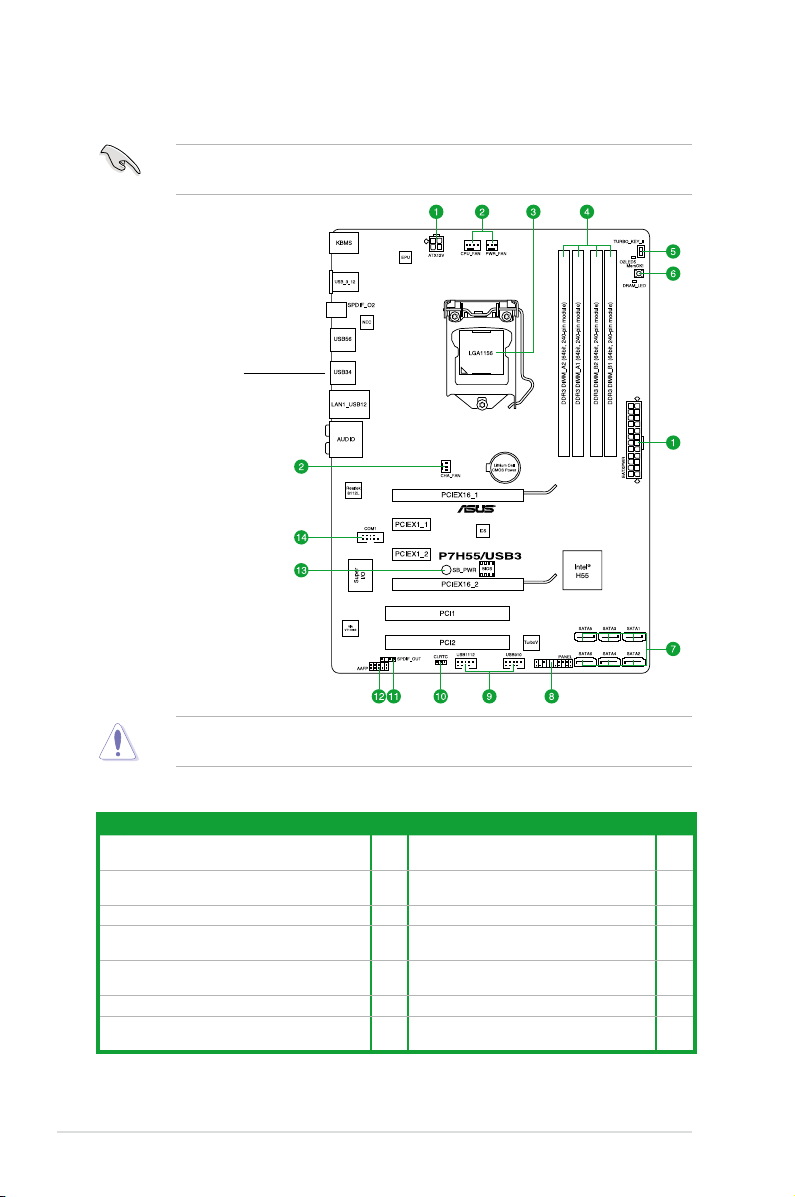
1.2.2 Layout contents
Connectors/Jumpers/Slots/LED Page Connectors/Jumpers/Slots/LED Page
ATX power connectors
1.
(24-pin EATXPWR, 4-pin EATX12V)
CPU, chassis, and power fan connectors (4-pin
2.
CPU_FAN, 3-pin CHA_FAN, 3-pin PWR_FAN)
3. LGA1156 CPU Socket 1-3 10. Clear RTC RAM (3-pin CLRTC) 1-18
4. DDR3 DIMM slots 1-8 11.
5. Turbo Key II switch 1-20 12.
6. MemOK! switch 1-19 13. Onboard LED 1-1
Intel® H55 Serial ATA connectors
7.
(7-pin SATA 1-6)
1-2 Chapter 1: Product introduction
1-22 8. System panel connector (20-8 pin PANEL) 1-26
1-23 9.
1-25 14. Serial port connector (10-1 pin COM1) 1-24
USB connectors (10-1 pin USB910,
USB1112)
Digital audio connector
(4-1 pin SPDIF_OUT)
Front panel audio connector
(10-1 pin AAFP)
1-27
1-23
1-24
1.3 Central Processing Unit (CPU)
A
B
The motherboard comes with a surface mount LGA1156 socket designed for the Intel®
Ensure that all power cables are unplugged before installing the CPU.
• Upon purchase of the motherboard, ensure that the PnP cap is on the socket and the
socket contacts are not bent. Contact your retailer immediately if the PnP cap is missing,
or if you see any damage to the PnP cap/socket contacts/motherboard components.
ASUS will shoulder the cost of repair only if the damage is shipment/transit-related.
• Keep the cap after installing the motherboard. ASUS will process Return Merchandise
Authorization (RMA) requests only if the motherboard comes with the cap on the
LGA1156 socket.
• The product warranty does not cover damage to the socket contacts resulting from
incorrect CPU installation/removal, or misplacement/loss/incorrect removal of the PnP
cap.
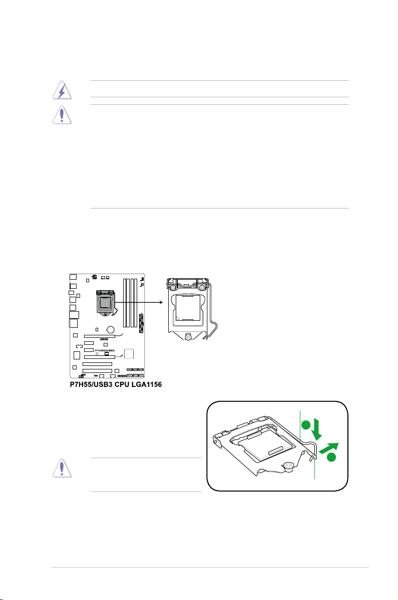
1.3.1 Installing the CPU
To install a CPU:
1. Locate the CPU socket on the motherboard.
2. Press the load lever with your thumb (A),
and then move it to the right (B) until it is
Load lever
released from the retention tab.
To prevent damage to the socket pins,
do not remove the PnP cap unless
you are installing a CPU.
Retention tab
ASUS P7H55/USB3 1-3

3. Lift the load lever in the direction of the
arrow until the load plate is completely
lifted.
4. Remove the PnP cap from the CPU
socket by lifting the tab only.
Load plate
PnP cap
Cap tab
5. Position the CPU over the socket,
ensuring that the gold triangle is on the
bottom-left corner of the socket, and then
t the socket alignment keys into the CPU
CPU notches
notches.
The CPU ts in only one correct
orientation. DO NOT force the CPU
into the socket to prevent bending
the connectors on the socket and
damaging the CPU!
1-4 Chapter 1: Product introduction
Gold
triangle
mark
Alignment keys
B
A
C
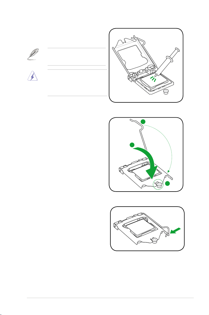
6. Apply some Thermal Interface Material
to the exposed area of the CPU that the
heatsink will be in contact with, ensuring
that it is spread in an even thin layer.
Some heatsinks come with preapplied thermal paste. If so, skip this
step.
The Thermal Interface Material is
toxic and inedible. DO NOT eat it. If
it gets into your eyes or touches your
skin, wash it off immediately, and seek
professional medical help.
7. Close the load plate (A), and then push
down the load lever (B), ensuring that
the front edge of the load plate slides
under the retention knob (C).
8. Insert the load lever under the retention
tab.
ASUS P7H55/USB3 1-5
1.3.2 Installing the CPU heatsink and fan
The Intel® LGA1156 processor requires a specially designed heatsink and fan assembly to
ensure optimum thermal condition and performance.
• When you buy a boxed Intel® processor, the package includes the CPU fan and heatsink
assembly. If you buy a CPU separately, ensure that you use only
Intel®-certied multi-directional heatsink and fan.
• Your Intel® LGA1156 heatsink and fan assembly comes in a push-pin design and
requires no tool to install.
• Use an LGA1156-compatible CPU heatsink and fan assembly only. The LGA1156 socket
is incompatible with the LGA775 and LGA1366 sockets in size and dimension.
If you purchased a separate CPU heatsink and fan assembly, ensure that the Thermal
Interface Material is properly applied to the CPU heatsink or CPU before you install the
heatsink and fan assembly.
Ensure that you have installed the motherboard to the chassis before you install the CPU
fan and heatsink assembly.
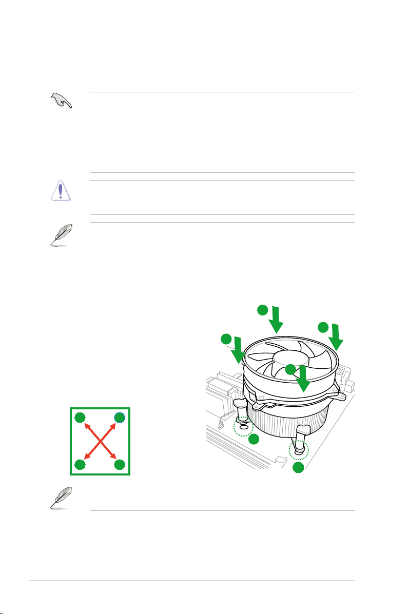
To install the CPU heatsink and fan:
1. Place the heatsink on top of the installed
CPU, making sure that the four fasteners
match the holes on the motherboard.
2. Push down two fasteners at a time in
a diagonal sequence to secure the
heatsink and fan assembly in place.
B
A
B
A
A
B
1
B
1-6 Chapter 1: Product introduction
A
Orient the heatsink and fan assembly such that the CPU fan cable is closest to the CPU fan
connector.
1

3. Connect the CPU fan cable to the connector on the motherboard labeled CPU_FAN.
DO NOT forget to connect the CPU fan connector! Hardware monitoring errors can occur if
you fail to plug this connector.
1.3.3 Uninstalling the CPU heatsink and fan
To uninstall the CPU heatsink and fan:
1. Disconnect the CPU fan cable from the
connector on the motherboard.
2. Rotate each fastener counterclockwise.
3. Pull up two fasteners at a time in a
diagonal sequence to disengage the
heatsink and fan assembly from the
motherboard.
B
A
B
A
A
B
B
A
4. Carefully remove the heatsink and fan assembly from the motherboard.
ASUS P7H55/USB3 1-7
1.4 System memory
1.4.1 Overview
The motherboard comes with four Double Data Rate 3 (DDR3) Dual Inline Memory Modules
(DIMM) sockets.
A DDR3 module has the same physical dimensions as a DDR2 DIMM but is notched
differently to prevent installation on a DDR2 DIMM socket. DDR3 modules are developed for
better performance with less power consumption.
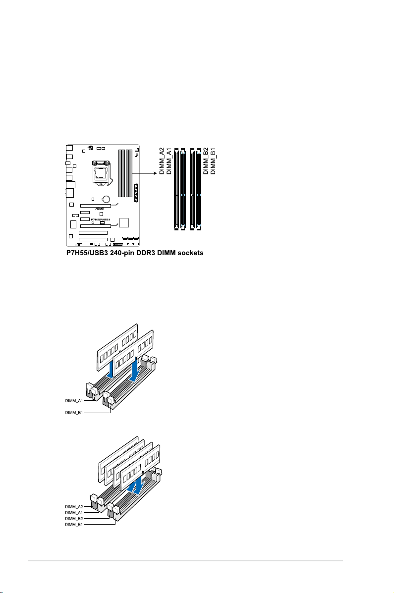
The gure illustrates the location of the DDR3 DIMM sockets:
Recommended memory congurations
One DIMM:
Install one memory module in slot A1 or B1 rst as a single-channel operation.
Two DIMMs (dual-channel operation):
Four DIMMs (dual-channel operation):
1-8 Chapter 1: Product introduction

1.4.2 Memory congurations
You may install 1GB, 2GB and 4GB unbuffered and non-ECC DDR3 DIMMs into the DIMM
sockets.
• You may install varying memory sizes in Channel A and Channel B. The system maps
the total size of the lower-sized channel for the dual-channel conguration. Any excess
memory from the higher-sized channel is then mapped for single-channel operation.
• According to Intel spec denition, DDR3-1600 is supported for one DIMM per channel
only. ASUS exclusively provides two DDR3-1600 DIMM support for each memory
channel.
• According to Intel CPU spec, DIMM voltage below 1.65V is recommended to protect the
CPU.
• According to Intel CPU spec, CPUs with a core frequency of 2.66G support the
maximum DIMM frequency of up to DDR3-1333. To use DIMMs of a higher frequency
with a 2.66G CPU, enable the DRAM O.C. Prole feature in BIOS. Refer to section 2.4
Ai Overclock Tuner for details.
• Always install DIMMs with the same CAS latency. For optimum compatibility, we
recommend that you obtain memory modules from the same vendor.
• Due to the memory address limitation on 32-bit Windows OS, when you install 4GB
or more memory on the motherboard, the actual usable memory for the OS can be
about 3GB or less. For effective use of memory, we recommend that you do any of the
following:
- Use a maximum of 3GB system memory if you are using a 32-bit Windows OS.
- Install a 64-bit Windows OS when you want to install 4GB or more on the motherboard.
For more details, refer to the Microsoft® support site at
http://support.microsoft.com/kb/929605/en-us.
• This motherboard does not support DIMMs made up of 512Mb (64MB) chips or less
(Memory chip capacity counts in Megabit, 8 Megabit/Mb = 1 Megabyte/MB).
• The default memory operation frequency is dependent on its Serial Presence Detect
(SPD), which is the standard way of accessing information from a memory module.
Under the default state, some memory modules for overclocking may operate at a lower
frequency than the vendor-marked value. To operate at the vendor-marked or at a higher
frequency, refer to section Ai Tweaker menu for manual memory frequency adjustment.
• For system stability, use a more efcient memory cooling system to support a full
memory load (4 DIMMs) or overclocking condition.
ASUS P7H55/USB3 1-9
 Loading...