


TERMINATOR 2 T2-R
ASUS TERMINATOR 2 T2-R User Guide
Barebone System
MODE
Model T2-R
User Guide
Terminator 2

E1557
Revised Edition V3
March 2004
Copyright © 2004 ASUSTeK COMPUTER INC. All Rights Reserved.
No part of this manual, including the products and software described in it, may be
reproduced, transmitted, transcribed, stored in a retrieval system, or translated into any
language in any form or by any means, except documentation kept by the purchaser for
backup purposes, without the express written permission of ASUSTeK COMPUTER INC.
(“ASUS”).
Product warranty or service will not be extended if: (1) the product is repaired, modified or
altered, unless such repair, modification of alteration is authorized in writing by ASUS; or (2)
the serial number of the product is defaced or missing.
ASUS PROVIDES THIS MANUAL “AS IS” WITHOUT WARRANTY OF ANY KIND, EITHER
EXPRESS OR IMPLIED, INCLUDING BUT NOT LIMITED TO THE IMPLIED WARRANTIES
OR CONDITIONS OF MERCHANTABILITY OR FITNESS FOR A PARTICULAR PURPOSE.
IN NO EVENT SHALL ASUS, ITS DIRECTORS, OFFICERS, EMPLOYEES OR AGENTS BE
LIABLE FOR ANY INDIRECT, SPECIAL, INCIDENTAL, OR CONSEQUENTIAL DAMAGES
(INCLUDING DAMAGES FOR LOSS OF PROFITS, LOSS OF BUSINESS, LOSS OF USE
OR DATA, INTERRUPTION OF BUSINESS AND THE LIKE), EVEN IF ASUS HAS BEEN
ADVISED OF THE POSSIBILITY OF SUCH DAMAGES ARISING FROM ANY DEFECT OR
ERROR IN THIS MANUAL OR PRODUCT.
SPECIFICATIONS AND INFORMATION CONTAINED IN THIS MANUAL ARE FURNISHED
FOR INFORMATIONAL USE ONLY, AND ARE SUBJECT TO CHANGE AT ANY TIME
WITHOUT NOTICE, AND SHOULD NOT BE CONSTRUED AS A COMMITMENT BY ASUS.
ASUS ASSUMES NO RESPONSIBILITY OR LIABILITY FOR ANY ERRORS OR
INACCURACIES THAT MAY APPEAR IN THIS MANUAL, INCLUDING THE PRODUCTS
AND SOFTWARE DESCRIBED IN IT.
Products and corporate names appearing in this manual may or may not be registered
trademarks or copyrights of their respective companies, and are used only for identification or
explanation and to the owners’ benefit, without intent to infringe.
2

Table of contents
Notices ........................................................................................... 6
Safety information .......................................................................... 7
About this guide.............................................................................. 8
System package contents ............................................................ 10
Chapter 1: System introduction
1.1 Welcome! ............................................................................ 12
1.2 Front panel (external) .......................................................... 12
1.3 Front panel (internal) ........................................................... 15
1.4 Rear panel........................................................................... 17
1.5 Internal components............................................................ 19
1.6 LED panel............................................................................ 20
Chapter 2: Basic installation
2.1 Preparation.......................................................................... 22
2.2 Before you proceed ............................................................. 22
2.3 Removing the cover ............................................................ 23
2.4 Removing the power supply ................................................ 24
2.5 Installing a CPU................................................................... 25
2.5.1 Removing the CPU fan and heatsink assembly.... 25
2.5.2 CPU installation..................................................... 26
2.5.3 Re-installing the CPU fan and heatsink assembly 27
2.6 Installing a DIMM................................................................. 28
2.6.1 Memory configurations.......................................... 28
2.6.2 DIMM installation................................................... 29
2.7 Installing an expansion card................................................ 30
2.7.1 Expansion slots ..................................................... 30
2.7.2 Expansion card installation ................................... 31
2.7.3 Configuring an expansion card ............................. 32
2.8 Installing a second optical drive .......................................... 33
2.9 Installing a hard disk drive................................................... 35
2.10 Re-installing the power supply unit...................................... 37
2.10.1 Voltage selector..................................................... 38
2.10.2 Power supply specifications .................................. 39
2.11 Replacing the cover............................................................. 40
2.12 Connecting external devices ............................................... 41
To the front panel................................................................. 41
To the rear panel ................................................................. 42
3

Table of contents
Chapter 3: Starting up
3.1 Installing an operating system............................................. 44
3.2 Powering up ........................................................................ 44
3.3.1 Running the support CD........................................ 45
3.3.2 Drivers menu......................................................... 45
3.3.3 Utilities................................................................... 46
3.3.4 ASUS contact information ..................................... 47
3.3.5 Other information .................................................. 47
3.4 Software information ........................................................... 48
3.4.1 Multi-channel audio feature................................... 48
3.4.2 ASUS Radio Player............................................... 51
3.4.3 ASUS Instant Music .............................................. 53
3.5 Audio DJ.............................................................................. 55
3.5.1 Playing an audio CD/DVD..................................... 55
3.5.2 Tuning into an FM radio station............................. 55
3.5.3 Presetting a station ............................................... 56
3.5.4 Adjusting the volume............................................. 56
3.6 ASUS Wireless LAN adapter............................................... 57
3.6.1 LED indicators....................................................... 58
3.6.2 Antenna installation............................................... 58
3.6.3 Installing the WLAN Card utilities and driver......... 59
3.6.4 Other support CD options ..................................... 59
3.6.5 The Control Center utility ...................................... 60
Chapter 4: Motherboard info
4.1 Introduction.......................................................................... 72
4.2 Motherboard layout ............................................................. 72
4.3 Jumper ................................................................................ 73
4.4 Internal connectors.............................................................. 74
Chapter 5: BIOS setup
5.1 Managing and updating your BIOS ..................................... 82
5.1.1 Creating a bootable floppy disk............................. 82
5.1.2 Using AFUDOS to copy the current BIOS............. 83
5.1.3 Using AFUDOS to update the BIOS...................... 84
5.1.4 Using ASUS EZ Flash to update the BIOS ........... 86
5.1.5 Recovering the BIOS with CrashFree BIOS 2 ...... 87
5.1.6 ASUS Update........................................................ 89
4

Table of contents
5.2 BIOS Setup program ........................................................... 91
5.2.1 BIOS menu screen................................................ 92
5.2.2 Menu bar ............................................................... 92
5.2.3 Navigation keys..................................................... 92
5.2.4 Menu items............................................................ 93
5.2.5 Sub-menu items .................................................... 93
5.2.6 Configuration fields ............................................... 93
5.2.7 Pop-up window...................................................... 93
5.2.8 Scroll bar ............................................................... 93
5.2.9 General help.......................................................... 93
5.3 Main menu........................................................................... 94
5.3.1 System Time ......................................................... 94
5.3.2 System Date.......................................................... 94
5.3.3 Legacy Diskette A ................................................. 94
5.3.4 Primary and Secondary IDE Master/Slave............ 95
5.3.5 System Information ............................................... 96
5.4 Advanced menu .................................................................. 97
5.4.1 Instant Music Configuration................................... 98
5.4.2 CPU Configuration ................................................ 99
5.4.3 Chipset .................................................................. 99
5.4.4 Onboard Devices Configuration .......................... 102
5.4.5 PCI PnP .............................................................. 103
5.5 Power menu ...................................................................... 105
5.5.1 Suspend Mode .................................................... 105
5.5.2 Repost Video on S3 Resume.............................. 105
5.5.3 ACPI 2.0 Support ................................................ 105
5.5.4 ACPI APIC Support ............................................. 105
5.5.5 APM Configuration .............................................. 106
5.5.6 Hardware Monitor................................................ 107
5.6 Boot menu ......................................................................... 109
5.6.1 Boot Device Priority............................................. 109
5.6.2 Boot Settings Configuration .................................110
5.6.3 Security ................................................................ 111
5.7 Exit menu ...........................................................................114
Appendix
A.1 Wireless LAN adapter channels ......................................... A-2
5

Notices
Federal Communications Commission Statement
This device complies with Part 15 of the FCC Rules. Operation is subject
to the following two conditions:
• This device may not cause harmful interference, and
• This device must accept any interference received including
interference that may cause undesired operation.
This equipment has been tested and found to comply with the limits for a
Class B digital device, pursuant to Part 15 of the FCC Rules. These limits
are designed to provide reasonable protection against harmful interference
in a residential installation. This equipment generates, uses and can
radiate radio frequency energy and, if not installed and used in
accordance with manufacturer’s instructions, may cause harmful
interference to radio communications. However , there is no guarantee that
interference will not occur in a particular installation. If this equipment does
cause harmful interference to radio or television reception, which can be
determined by turning the equipment off and on, the user is encouraged to
try to correct the interference by one or more of the following measures:
• Reorient or relocate the receiving antenna.
• Increase the separation between the equipment and receiver.
• Connect the equipment to an outlet on a circuit different from that
to which the receiver is connected.
• Consult the dealer or an experienced radio/TV technician for help.
WARNING! The use of shielded cables for connection of the monitor
to the graphics card is required to assure compliance with FCC
regulations. Changes or modifications to this unit not expressly
approved by the party responsible for compliance could void the user’s
authority to operate this equipment.
Canadian Department of Communications Statement
This digital apparatus does not exceed the Class B limits for radio noise
emissions from digital apparatus set out in the Radio Interference
Regulations of the Canadian Department of Communications.
This class B digital apparatus complies with Canadian ICES-003.
6

Safety information
Electrical safety
• To prevent electrical shock hazard, disconnect the power cable
from the electrical outlet before relocating the system.
• When adding or removing devices to or from the system, ensure
that the power cables for the devices are unplugged before the
signal cables are connected.
• If the power supply is broken, do not try to fix it by yourself.
Contact a qualified service technician or your retailer.
Operation safety
• Before installing devices into the system, carefully read all the
documentation that came with the package.
• Before using the product, make sure all cables are correctly
connected and the power cables are not damaged. If you detect
any damage, contact your dealer immediately.
• To avoid short circuits, keep paper clips, screws, and staples
away from connectors, slots, sockets, and circuitry.
• Avoid dust, humidity, and temperature extremes. Do not place the
product in any area where it can get wet. Place the product on a
stable surface.
• If you encounter technical problems with the product, contact a
qualified service technician or your retailer.
Lithium-Ion Battery Warning
CAUTION: Danger of explosion if battery is incorrectly replaced.
Replace only with the same or equivalent type recommended by
the manufacturer. Dispose of used batteries according to the
manufacturer’s instructions.
VORSICHT: Explosionsgetahr bei unsachgemäßen Austausch der
Batterie. Ersatz nur durch denselben oder einem vom Hersteller
empfohlenem ähnljchen Typ. Entsorgung gebrauchter Batterien
nach Angaben des Herstellers.
LASER PRODUCT WARNING
CLASS 1 LASER PRODUCT
7

Safeguards
About this guide
Audience
This guide provides general information on the ASUS Terminator 2
barebone system. Included in this guide are installation instructions and
other information regarding the system. This guide is intended for
experienced users and integrators with hardware knowledge of personal
computers.
How this guide is organized
This guide contains the following parts:
1. Chapter 1: System introduction
This chapter gives a general description of the ASUS Terminator 2.
The chapter lists the system features, including introduction on the
front and rear panel, and internal components.
2. Chapter 2: Basic installation
This chapter provides step-by-step instructions on how to install
components in the system.
3. Chapter 3: Starting up
This chapter helps you power up the system and install drivers and
utilities from the support CD.
4. Chapter 4: Motherboard information
This chapter gives information about the motherboard that comes
with the system. This chapter includes the motherboard layout,
jumper settings, and connector locations.
5. Chapter 5: BIOS setup
This chapter tells how to change system settings through the BIOS
Setup menus and describes the BIOS parameters.
6. Appendix
The Appendix includes the IEEE 802.11b channels for the wireless
LAN adapter (available on Deluxe-Commercial models only).
8

Conventions used in this guide
WARNING: Information to prevent injury to yourself when trying to
complete a task.
CAUTION: Information to prevent damage to the components
when trying to complete a task.
IMPORTANT: Instructions that you MUST follow to complete a task.
NOTE: Tips and additional information to help you complete a task.
Where to find more information
Refer to the following sources for additional information and for product
and software updates.
1. ASUS websites
The ASUS websites worldwide provide updated information on ASUS
hardware and software products. Refer to the ASUS contact
information.
2. Optional documentation
Your product package may include optional documentation, such as
warranty flyers, that may have been added by your dealer. These
documents are not part of the standard package.
9
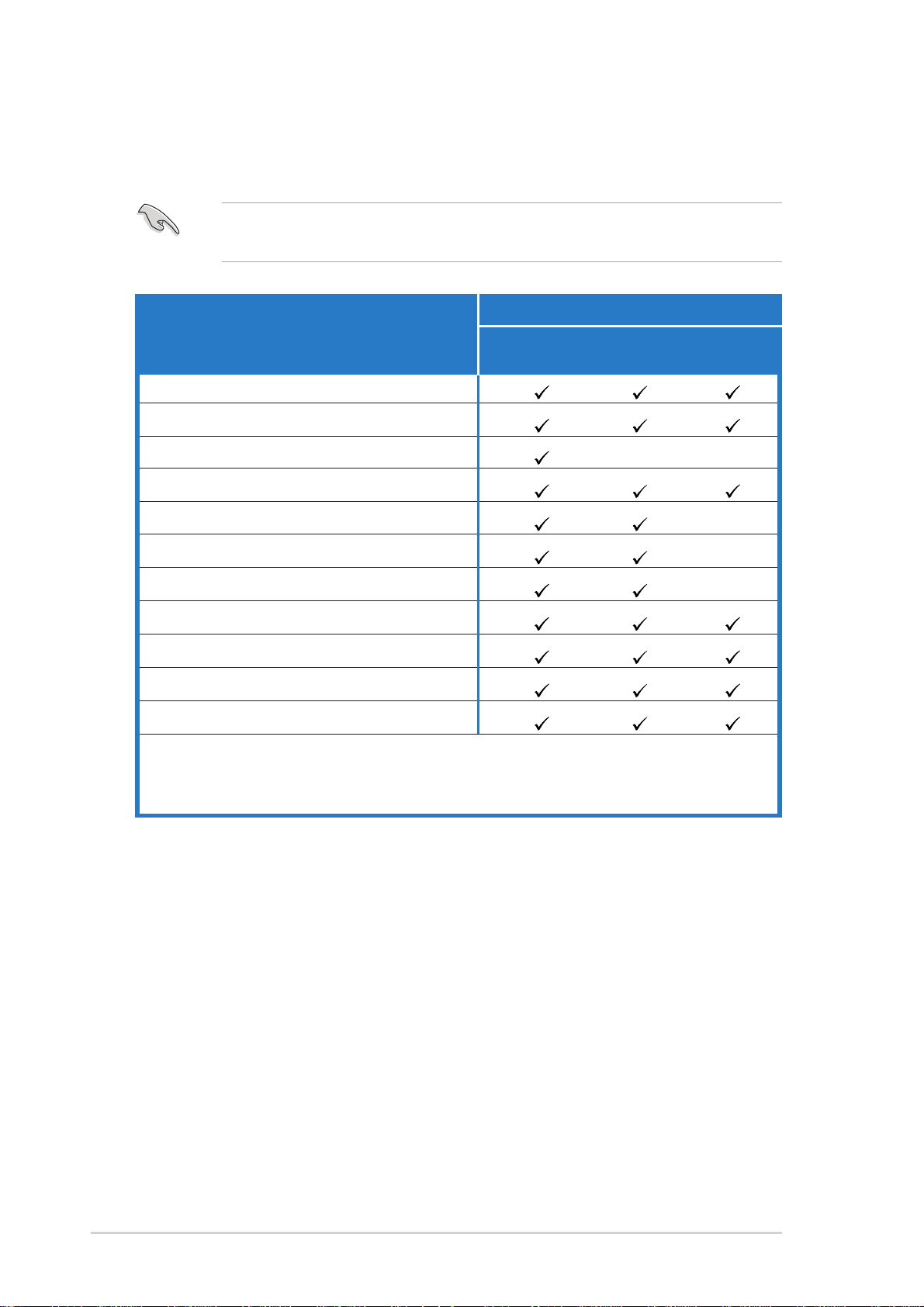
System package contents
Check your Terminator 2 system package for the following items.
If any of the items is damaged or missing, contact your retailer
immediately.
T2-R Models
Item Description Commercial Deluxe Standard
Deluxe
1. ASUS Terminator 2 barebone system with
• ASUS P4R8T motherboard
• 3-in-1 PCI card*
• Floppy disk drive
• 7-in-1 storage card reader
• FM radio module and radio antenna
• LED panel
• CPU fan and heatsink assembly
2. AC power cable
3. Support CD
4. User guide
Optional items
• Optical drive**
• Modem module
* IEEE 1394, wireless LAN adapter (with dipolar antenna), and Gigabit LAN
** CD-ROM/CD-RW/DVD-ROM/DVD-RW
10
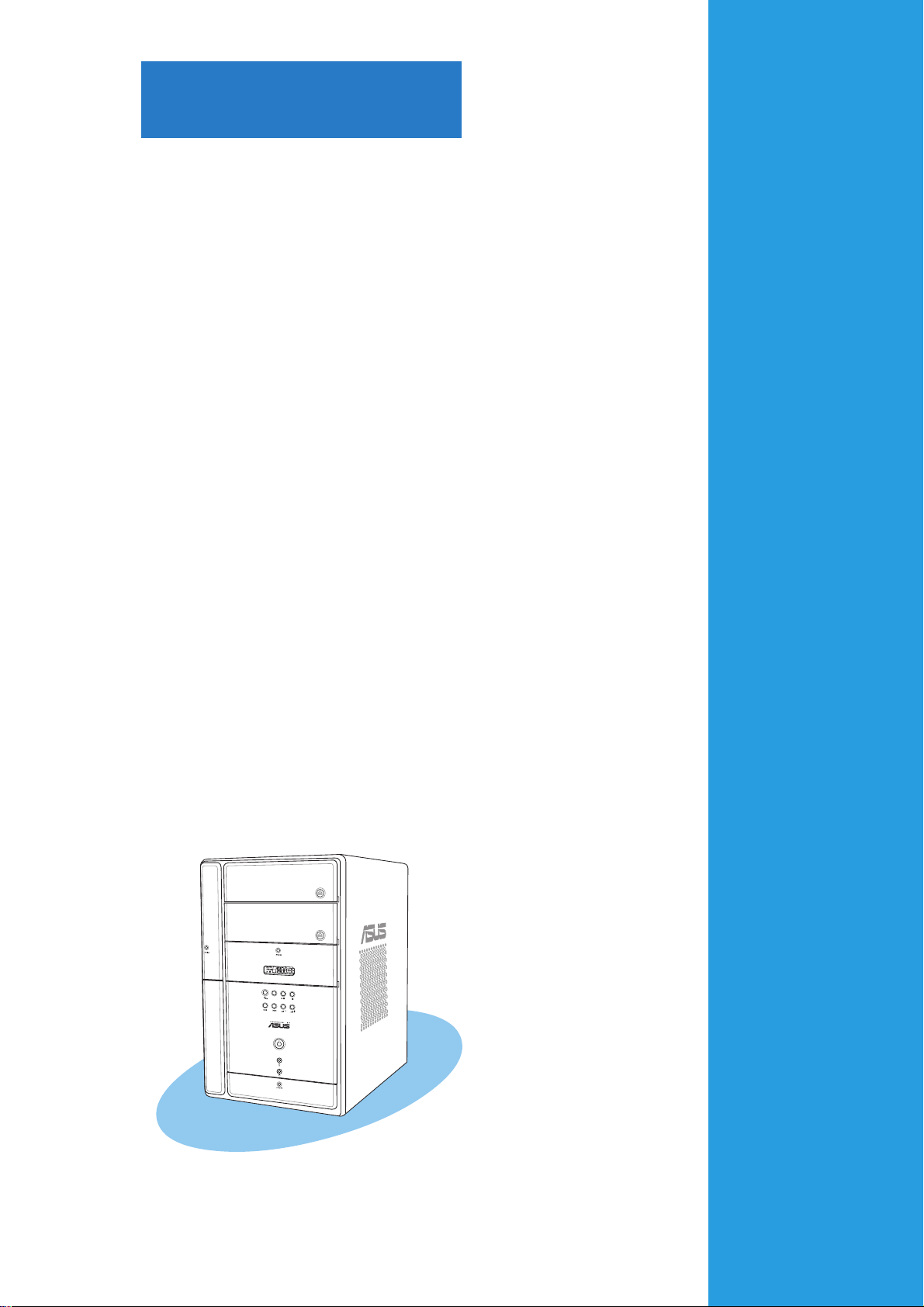
Chapter 1
This chapter gives a general
description of the ASUS
Terminator 2. The chapter lists the
system features, including
introduction on the front and rear
panel, and internal components.
MODE
ASUS Terminator 2 barebone system
System introduction
1.1 Welcome!
Thank you for choosing the ASUS Terminator 2!
The ASUS Terminator 2 is an all-in-one barebone system with a versatile
home entertainment feature.
Delivered in a stylish mini-tower casing and powered by the ASUS P4R8T
motherboard that supports Intel
®
Pentium® 4 processor with an 800MHz
FSB, and up to 2GB system memory, the Terminator 2 system is designed
for the sophisticated.
Superb video and audio capabilities, Fast Ethernet/wireless networking,
and extensive connectivity are just some of the many features of the
Terminator 2 system. With these and many more, the Terminator 2
definitely delivers the cutting edge technology for your computing and
multimedia needs!
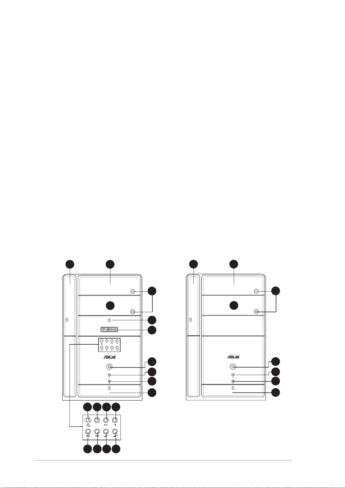
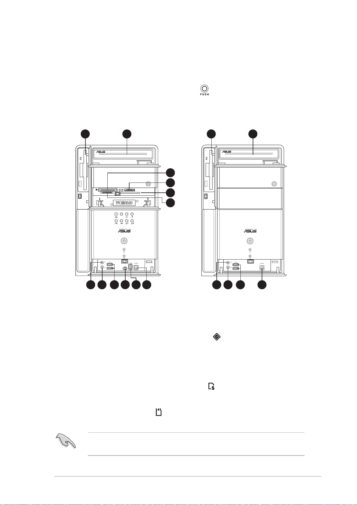
1.2 Front panel (external)
The front panel includes the system and audio control buttons, system
LEDs, and LED panel.
Commercial Deluxe &
Standard model
Deluxe model
21
3
4
9
10
MODE
5
6
7
21
3
4
5
6
7
12
11 12 13 14
MODE
15 16 17 18
8
8
Chapter 1: System introduction

1. Floppy drive door. Open this door to access the floppy disk drive.
2. Optical drive door. This door opens when you eject the loading tray .
3. Eject button. Press this button to eject the loading tray of the optical
drive.
4. Empty drive bay door. This door covers an empty 5.25-inch drive
bay for a second optical drive.
5. Power button. Press this button to turn the system on.
6. Power LED. When lit, this LED indicates that the system is ON.
7. HDD LED. This LED lights up when data is being read from or written
to the hard disk drive
8. Front panel I/O door. Open this door to show the front panel input/
output ports.
9. Storage card reader door. Open this door to access the 7-in-1
storage card reader.
10. LED panel. The LED panel displays the audio medium (CD/FM),
radio frequency, player status (
/ ), real time clock, track number, and
time. See page 20 for details.
The following front panel buttons are activated only when the system is
in Audio DJ mode. The Audio DJ feature allows you to play CD audio
tracks, or tune into an FM radio station without entering the operating
system. See page 55 for details. The audio control buttons are
available only on Deluxe and Commercial Deluxe models.
11. CD button (
). Press this button to put the Audio DJ function to CD
mode.
In Windows® mode, pressing this button shuts down, restarts, or puts
the system in sleep mode (S3) depending on the OS setting.
12. Mode button. Press this button to switch from CD to FM radio mode
or vice versa.
ASUS Terminator 2 barebone system
13

13. PLAY/PAUSE button ( / ). Press this button to perform various
functions in different modes.
In CD mode, plays or pauses an audio CD track.
In Radio mode, scans the available FM stations when pressed for
less than two seconds or presets a station when pressed for more
than two seconds. Refer to page 55 on how to preset a radio station.
14. STOP button ( ). Press this button to stop playing the audio track.
15. PREVIOUS button (
in different modes.
In CD mode, selects the previous audio track.
In Radio mode, selects the previous preset station.
16. NEXT button (
different modes.
In CD mode, selects the next audio track.
In Radio mode, selects the next preset station.
17. Volume down button (
system volume.
18. Volume up button (
volume.
). Press this button to perform various functions in
). Press this button to perform various functions
–
). Press this button to decrease the
+
). Press this button to increase the system
14
Chapter 1: System introduction
1.3 Front panel (internal)
The optical drive(s), storage card reader slots, and several I/O ports are
located inside the front panel doors.
Open the front panel doors by pressing the
mark.
Commercial Deluxe
and Deluxe model
2019
21
22
23
24
MODE
Standard model
2019
25 26 27 28 29 30
28
25 26 27 30
19. Floppy disk drive. This drive is for 1.44MB, 3.5-inch floppy disk.
20. Optical drive. This is an IDE optical drive.
21. CompactFlash
®
/Microdrive™ card slot ( ). This slot is for a
CompactFlash®/Microdrive™ storage card.
22. Memory Stick
®
/Memory Stick Pro™ card slot. This slot is for a
Memory Stick®/Memory Stick Pro™ storage card.
23. Secure Digital™/MultimediaCard slot (
). This slot is for a Secure
Digital™/MultimediaCard storage card.
®
24. SmartMedia
card slot ( ). This slot is for a SmartMedia® storage
card.
You cannot close the storage card reader door if a storage card is
inserted into any of the card slots.
ASUS Terminator 2 barebone system
15

25. Headphone port. This port connects a headphone with a stereo
mini-plug.
26. Microphone port. This Mic (pink) port connects a microphone.
27. USB 2.0 ports. These Universal Serial Bus 2.0 (USB 2.0) ports are
available for connecting USB 2.0 devices such as a mouse, printer,
scanner, camera, PDA, and others.
28. 4-pin IEEE 1394 port. This port provides high-speed connectivity for
IEEE 1394-compliant audio/video devices, storage peripherals, and
other PC devices.
29. 6-pin IEEE 1394 port. This port provides high-speed connectivity for
IEEE 1394-compliant audio/video devices, storage peripherals, and
other PC devices.
30. Optical S/PDIF port. This port connects your audio system for
5.1-channel surround sound and enhanced 3D audio.
16
Chapter 1: System introduction
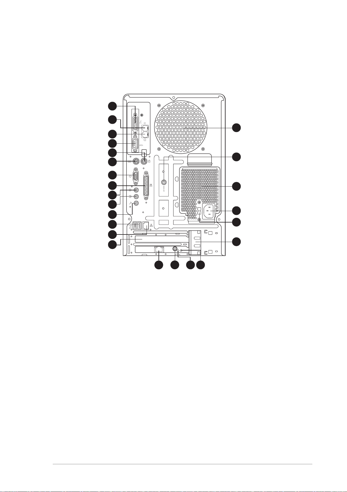
1.4 Rear panel
The system rear panel includes the power socket and several I/O ports
that allow convenient connection of devices.
Commercial Deluxe model
1
2
15
3
4
5
6
7
16
10
11
12
13
14
8
9
21
242322
17
18
19
20
1. GAME/MIDI port. This port connects a joystick, or game pad for
playing games, and MIDI devices for audio editing.
2. Telephone port
(optional)
. The optional modem module comes with
a telephone port. Connect one end of an RJ-11 cable to this port and
the other end to the RJ-11 port of the telephone unit.
3. RJ-11 port
(optional)
. The optional modem module comes with an
RJ-11 port to connect an RJ-11 cable jack. Connect one end of an
RJ-11 cable to this port and the other end to the RJ-11 wall socket.
4. Serial port. This port connects a mouse, modem, or other devices
that conforms with serial specification.
5. PS/2 mouse port. This green 6-pin connector is for a PS/2 mouse.
6. PS/2 keyboard port. This purple 6-pin connector is for a PS/2 keyboard.
7. VGA port. This port connects a VGA monitor.
ASUS Terminator 2 barebone system
17

8. Parallel port. This 25-pin port connects a printer, scanner, or other
devices.
9. Line Out port. This Line Out (lime) port connects a headphone or
speakers. In 4/6-channel mode, the function of this port becomes
Front Speaker Out.
10. Line In port. This Line In (light blue) port connects a tape player or
other audio sources. In 6-channel mode, the function of this port
becomes Low Frequency Enhanced Output/Center.
11. Microphone port. This Microphone (pink) port connects a
microphone. In 4/6-channel mode, the function of this port becomes
Surround speaker.
Audio ports function variation
Port Headphone/2-Channel 4-Channel 6-Channel
Light Blue Line In No function LFE Output*/Center
Lime Line Out Front Speaker Out Front Speaker Out
Pink Mic In Surround Surround
* Low Frequency Enhanced Output
12. USB 2.0 ports. These Universal Serial Bus 2.0 (USB 2.0) ports are
available for connecting USB 2.0 devices such as a mouse, printer,
scanner, camera, PDA, and others.
13. Ethernet LAN port. This port allows connection to a Local Area
Network (LAN) through a network hub.
14. AGP slot cover. Remove this cover when installing an AGP card.
15. Chassis fan. This fan provides ventilation inside the system chassis.
16. Radio antenna port. This port connects an optional radio antenna.
17. Power supply unit fan. This fan provides ventilation inside the
power supply unit.
18. Power socket. This socket connects the power cable and plug.
19. Voltage selector. This switch allows you to select the appropriate
voltage supply in your area. See the “Voltage selector” section on
page 38 before adjusting this switch.
20. Expansion card lock. This metal lock secures installed expansion
cards. See page 31 for details.
21. Gigabit LAN port.
(Commercial Deluxe models only.)
This port
allows high-speed connection to the Internet via an ADSL or cable
modem, or local area network.
18
Chapter 1: System introduction
22. Wireless LAN adapter antenna connector.
models only.)
This connects the dipolar antenna of the wireless LAN
adapter.
(Commercial Deluxe
23. Link LED.
(Commercial Deluxe models only.)
This yellow LED lights
up when the wireless LAN adapter radio is on but has no activity.
24. AIR LED.
(Commercial Deluxe models only.)
This green LED blinks
when the wireless LAN adapter is transmitting or receiving data.
See page 58 for the wireless LAN adapter LED indications.
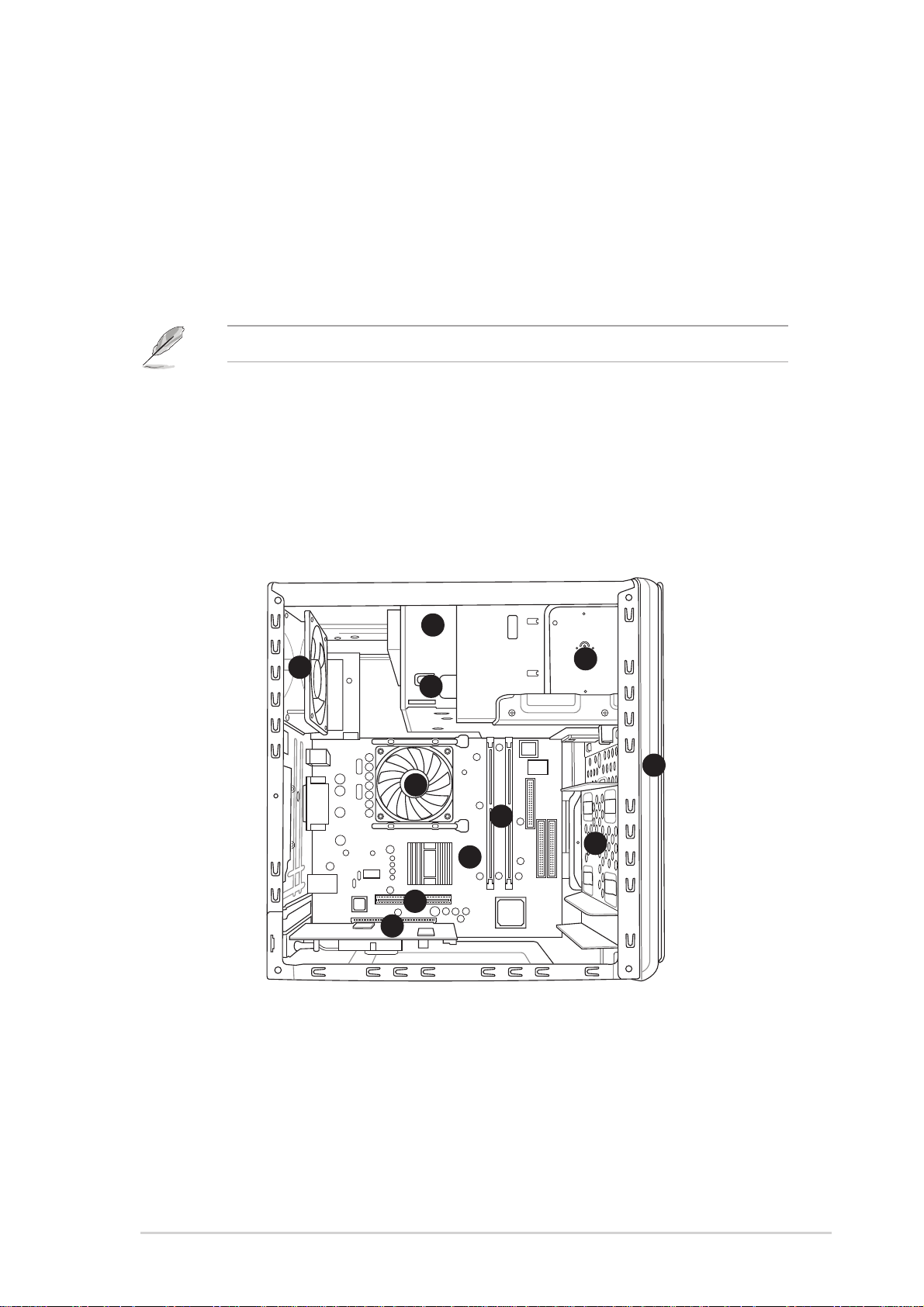
1.5 Internal components
The illustration below is the internal view of the system when you remove the
top cover and the power supply unit. The installed components are labeled
for your reference. Proceed to Chapter 2 for instructions on installing other
system components.
1
6
2
3
11
1. Optical drive
2. Empty 5.25-inch drive bay
3. Floppy disk drive
4. Front panel cover
5. Hard disk drive tray
6. Chassis fan
4
9
8
5
7
10
7. ASUS P4R8T motherboard
8. DIMM sockets
9. CPU fan and heatsink assembly
10.AGP slot
11. PCI slot (with an installed
PCI card)
ASUS Terminator 2 barebone system
19
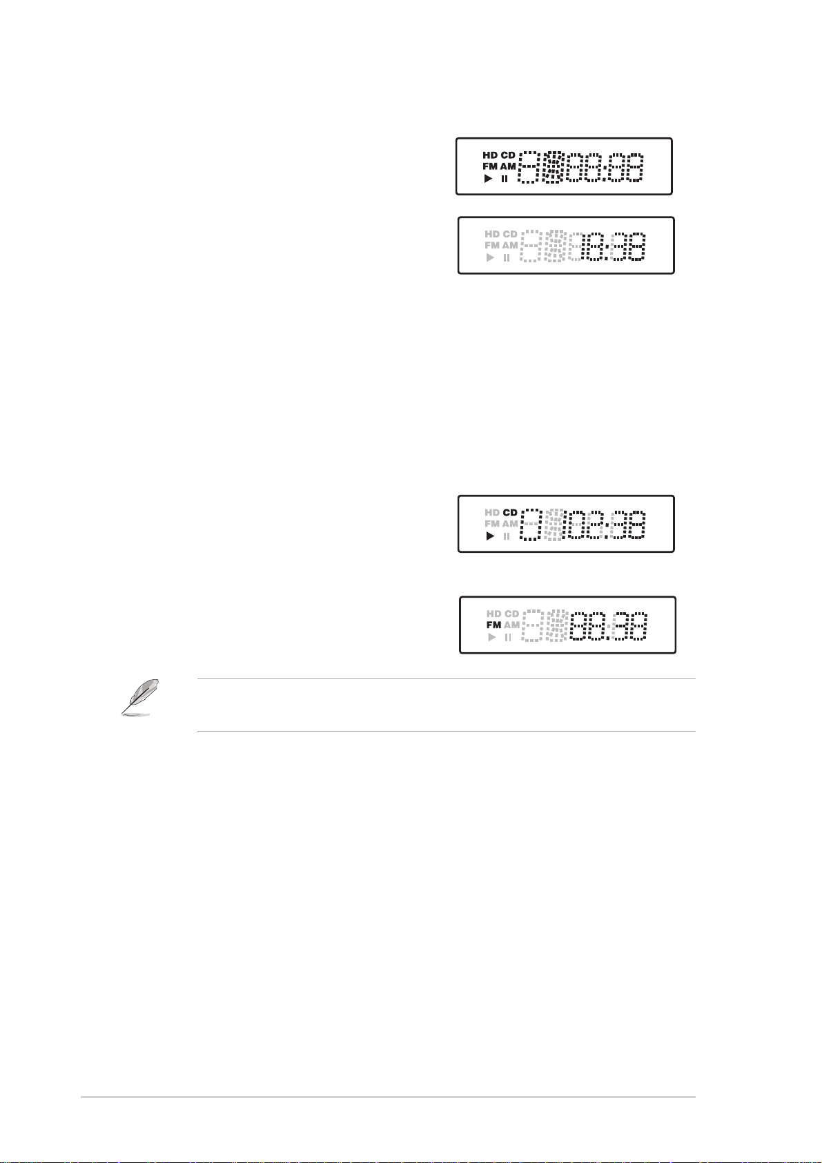
1.6 LED panel
The LED panel displays various system
information depending on the system
mode.
The LED panel displays the system time in
24-hour format when the system is in soft-off
or stand-by mode, S3 (Suspend-to-RAM), or
S4 (Suspend-to-Disk) state. Enter the BIOS
setup or the operating system to adjust the
time.
Audio DJ mode
The LED panel displays various information when the system is in Audio
DJ mode.
In CD mode, the LED panel displays the
play/pause icon, number, and duration of
the audio CD track being played.
In Radio mode, the LED panel displays
the station preset number and station
frequency.
Refer to page 55 on how to turn on the Audio DJ feature and how to
preset a radio station.
CD mode, play/paused status
FM radio mode
20
Chapter 1: System introduction
Chapter 2
This chapter provides step-by-step
instructions on how to install
components in the system.
MODE
ASUS Terminator 2 barebone system
Basic installation
2.1 Preparation
®
d
Before you proceed, make sure that you have all the components that you
plan to install in the system.
Basic components to install
1. Central processing unit (CPU)
2. DDR Dual Inline Memory Module (DIMM)
3. Expansion card(s)
4. Hard disk drive
5. Second optical drive
Tool
Phillips (cross) screw driver
2.2 Before you proceed
Take note of the following precautions before you install components into
the system.
• Use a grounded wrist strap or touch a safely grounded object or a
metal object, such as the power supply case, before handling
components to avoid damaging them due to static electricity.
• Hold components by the edges to avoid touching the ICs on them.
• Whenever you uninstall any component, place it on a grounded
antistatic pad or in the bag that came with the component.
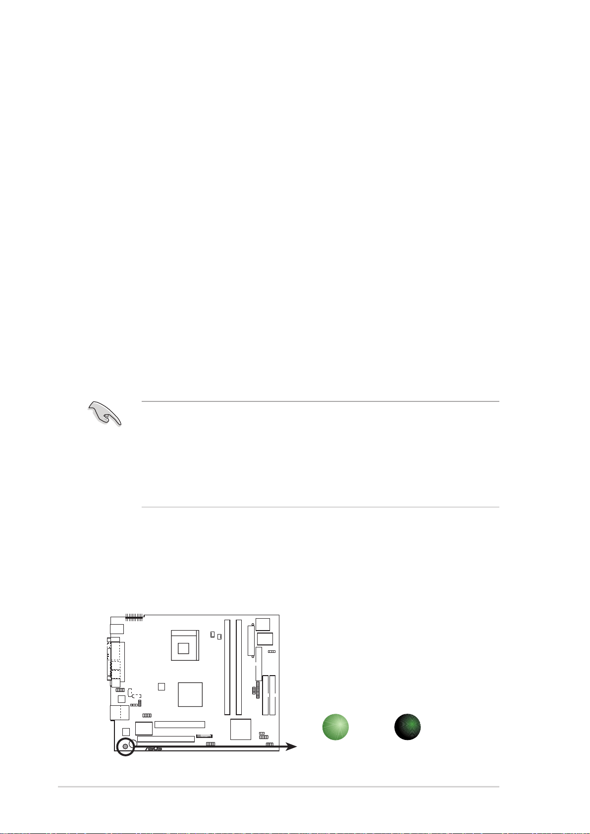
The motherboard comes with an onboard standby power LED. When lit,
this LED indicates that the system is ON, in sleep mode or in soft-off
mode, and not powered OFF. Unplug the power cable from the power
outlet and make sure that the standby power LED is OFF before installing
any system component.
SB_PWR
P4R8T
P4R8T Onboard LED
22
ON
Standby
Power
OFF
Powere
Off
Chapter 2: Basic installation

2.3 Removing the cover
To remove the cover:
1. On the rear panel, locate the
three screws that secure the
cover to the chassis.
2. Use a Phillips screw driver to
remove the cover screws. Keep
the screws for later use.
1
1 1
2
3. Slightly pull the cover toward
the rear panel until the side tabs
are disengaged from the
chassis.
4. Lift the cover, then set aside.
2
2
4
3
3
ASUS Terminator 2 barebone system
23
2.4 Removing the power supply
You must remove the power supply unit (PSU) before you can install a
central processing unit (CPU) and other system components.
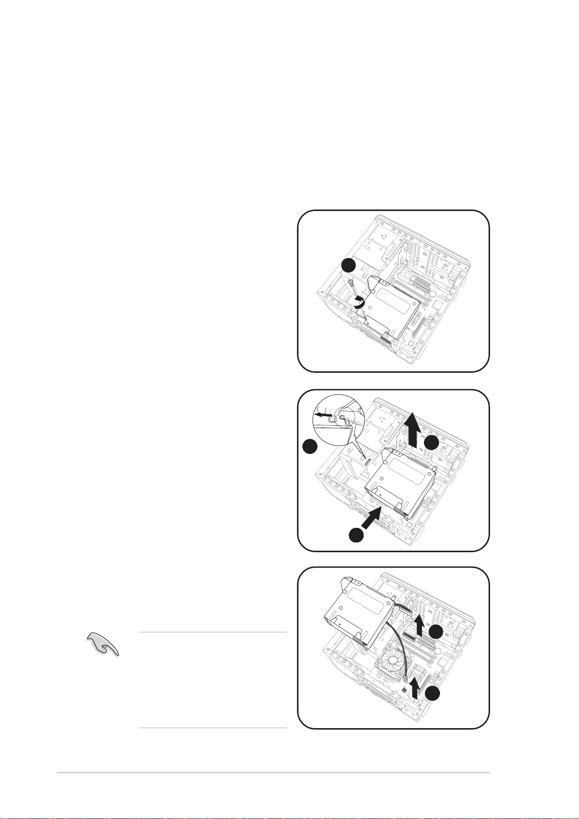
To remove the PSU:
1. Lay the system on its side on a flat, stable surface.
2. Disconnect the optical drive and floppy disk drive power plugs.
3. Remove the screw that secures
the PSU to the chassis.
3
4. Slide the PSU to the left until
the side hook is disengaged
from the chassis.
5. Push the PSU towards the front
panel for about half an inch.
6. Lift the PSU slightly.
7. Disconnect the power plugs on
the motherboard.
8. Set the PSU aside.
When removing the PSU,
make sure to hold or support
it firmly. The unit might
accidentally drop and
damage the other system
components.
4
5
6
7
7
24
Chapter 2: Basic installation
2.5 Installing a CPU
The motherboard comes with a surface mount 478-pin Zero Insertion
Force (ZIF) socket. This socket is designed for an Intel
Pentium® 4 processor with up to 800MHz FSB.
2.5.1 Removing the CPU fan and heatsink assembly
The system package includes a pre-installed proprietary CPU fan and
heatsink assembly to ensure optimum thermal condition and performance.
DO NOT replace the proprietary CPU fan and heatsink with other
models.
You must remove the CPU fan and heatsink assembly before you can
install a CPU.
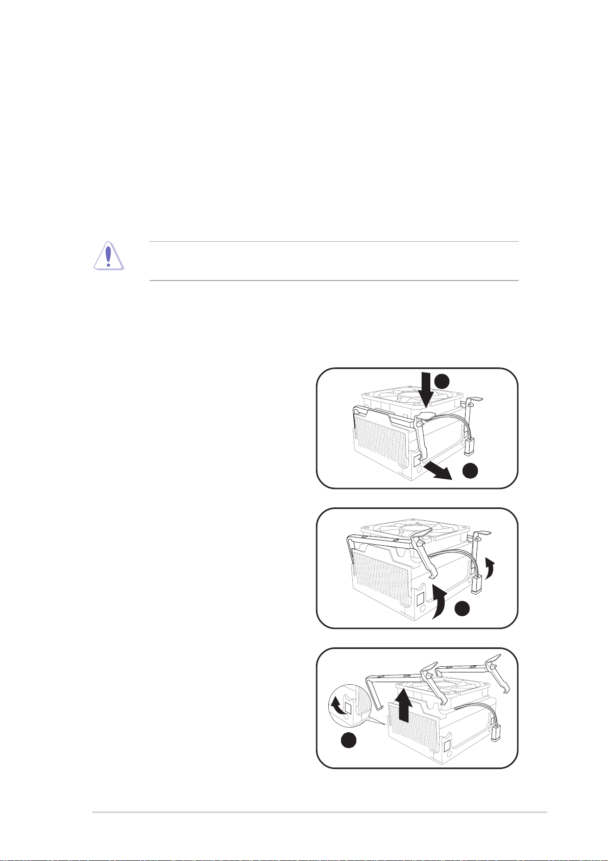
To remove the CPU fan and heatsink assembly:
®
1. Carefully press down the
locking lever of the retention
bracket.
2. Detach the retention bracket
hook from the retention module
hole by flipping the locking lever
to the direction of the arrow.
3. Slightly lift the retention bracket.
4. Detach the other retention
bracket hook from the hole on
the other side of the retention
module, then lift.
1
2
3
5. Do steps 1-4 to remove the
second retention bracket.
ASUS Terminator 2 barebone system
4
25
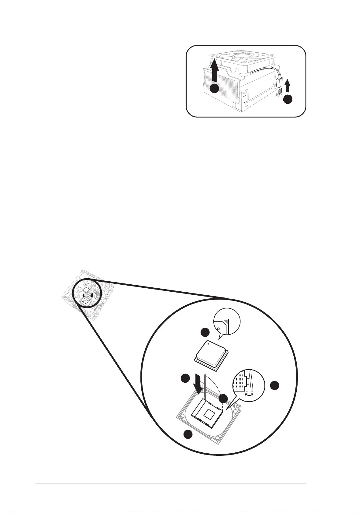
6. Disconnect the CPU fan cable
from the CPU fan connector on
the motherboard.
7. Lift the CPU fan and heatsink
assembly, then set aside.
7
6
2.5.2 CPU installation
To install the CPU:
1. Locate the 478-pin CPU socket on the motherboard.
2. Unlock the socket by pressing the lever sideways then lifting it up to a
90° angle.
3. Position the CPU above the socket such that its marked corner (gold
mark) matches the base of the socket lever.
4. Carefully insert the CPU into the socket until it fits in place.
5. Push down the socket lever to secure the CPU. The lever clicks on
the side tab to indicate that it is locked.
26
3
4
2
5
1
Chapter 2: Basic installation
2.5.3 Re-installing the CPU fan and heatsink
assembly
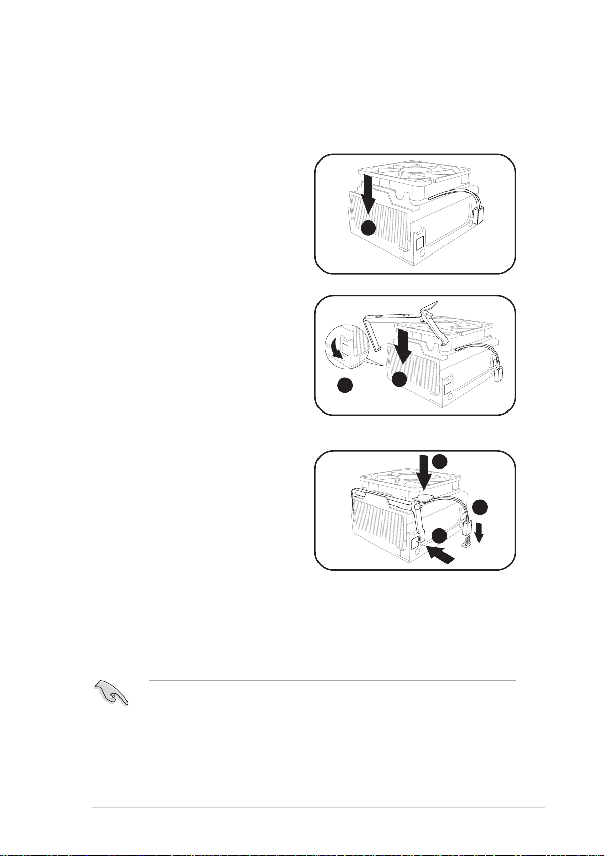
To re-install the CPU fan and heatsink assembly:
1. Position the CPU fan and
heatsink assembly on top of the
installed CPU.
1
2. Align the retention bracket with
the rails on the side of the CPU
fan.
3. Attach the retention bracket
hook into the retention module
hole.
3
2
4. Carefully press down the
4
locking lever on the other side
of the retention bracket.
5. Attach the locking lever hook
7
into the retention module hole
5
to secure the fan and heatsink
assembly in place.
6. Follow steps 2 to 5 to re-install
the second retention bracket.
7. Connect the CPU fan cable to the CPU fan connector on the
motherboard.
Do not forget to connect the CPU fan connector! Hardware monitoring
errors might occur if you fail to plug this connector.
ASUS Terminator 2 barebone system
27
2.6 Installing a DIMM
The motherboard comes with two Double Data Rate (DDR) Dual Inline
Memory Module (DIMM) sockets. These sockets support up to 2GB
system memory using unbuffered non-ECC PC3200/2700/2100 DIMMs.
• This motherboard supports one single-sided PC3200 (DDR400)
DIMM per channel only.
• This motherboard may only detect PC2700 (DDR333) system
memory when you install double-sided PC3200 (DDR400)
DIMMs.
2.6.1 Memory configurations
You can install 64MB, 128MB, 256MB, 512MB, and 1GB DDR DIMMs into
the DIMM sockets.
Obtain DDR DIMMs only from ASUS qualified vendors. Refer to the
table below. Visit the ASUS website (www.asus.com) for the latest
Qualified Vendors List.
Qualified DDR400 vendors
This table lists the memory modules that have been tested and qualified
for use with this motherboard.
Size Vendor Part Number Chip Brand Chip Number
256MB MICRON MT8VDDT3264AG-40BC4 MICRON 46V32M8
256MB PSC AL5D8B53T-5B1K PSC A2S56D30BTP
256MB TwinMOS M2G9108AIATT9F081AADT TwinMOS TMD7608F8E50D
256MB SAMSUNG M368L3223DTM-CC4 SAMSUNG K4H560838D-TCC4
256MB SAMSUNG M368L3223DTM-CCC SAMSUNG K4H560838D-TCCC
256MB Kingston KVR400X64C25/256 Winbond W9425088H-5
256MB Transcend TS32MLD64V4F3 MOSEL V58C2256804SAT5
256MB CORSAIR CMX256A-3500C2PT –– ––
256MB Infineon HYS64D32300GU-5-B Infineon HYB25D256800BT-5
• Install only identical (the same type and size) DDR DIMMs in
DIMM_A and DIMM_B.
28
• Always install DIMMs with the same CAS latency. For optimum
compatibility, obtain memory modules from the same vendor.
• This motherboard only supports x4, x8, x16 chips/per module DDR
DIMMs.
Chapter 2: Basic installation
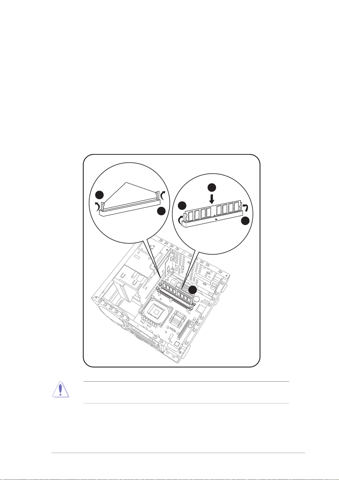
2.6.2 DIMM installation
To install a DDR DIMM.
1. Locate the two DIMM sockets on the motherboard.
2. Unlock a socket by pressing the retaining clips outward.
3. Align a DIMM on the socket such that the notch on the DIMM
matches the break on the socket.
4. Firmly insert the DIMM into the socket until the retaining clips snap
back in place and the DIMM is properly seated.
Retaining clips
3
2
2
4
4
1
A DDR DIMM is keyed with a notch so that it fits in only one direction.
DO NOT force a DIMM into a socket to avoid damaging the DIMM!
ASUS Terminator 2 barebone system
29
2.7 Installing an expansion card
®
In the future, you might need to install expansion cards. The motherboard
has one PCI and one Accelerated Graphics Port (AGP) slot. The following
sub-sections describe the slots and the expansion cards that they support.
For Commercial Deluxe models, a 3-in-1 PCI card is pre-installed in
the PCI slot. You may refer to this section when installing a different
PCI card on the PCI slot.
2.7.1 Expansion slots
PCI slot
The PCI slot supports PCI cards such as a LAN card, SCSI card, USB
card, and other cards that comply with PCI specifications.
AGP slot
The AGP slot supports AGP 8X (+0.8V) cards and AGP 4X (+1.5V) cards.
When you buy an AGP card, make sure that you ask for one with +0.8V or
+1.5V specification.
Install only +0.8V or +1.5V AGP cards. The P4P8T motherboard does
not support 3.3V AGP cards.
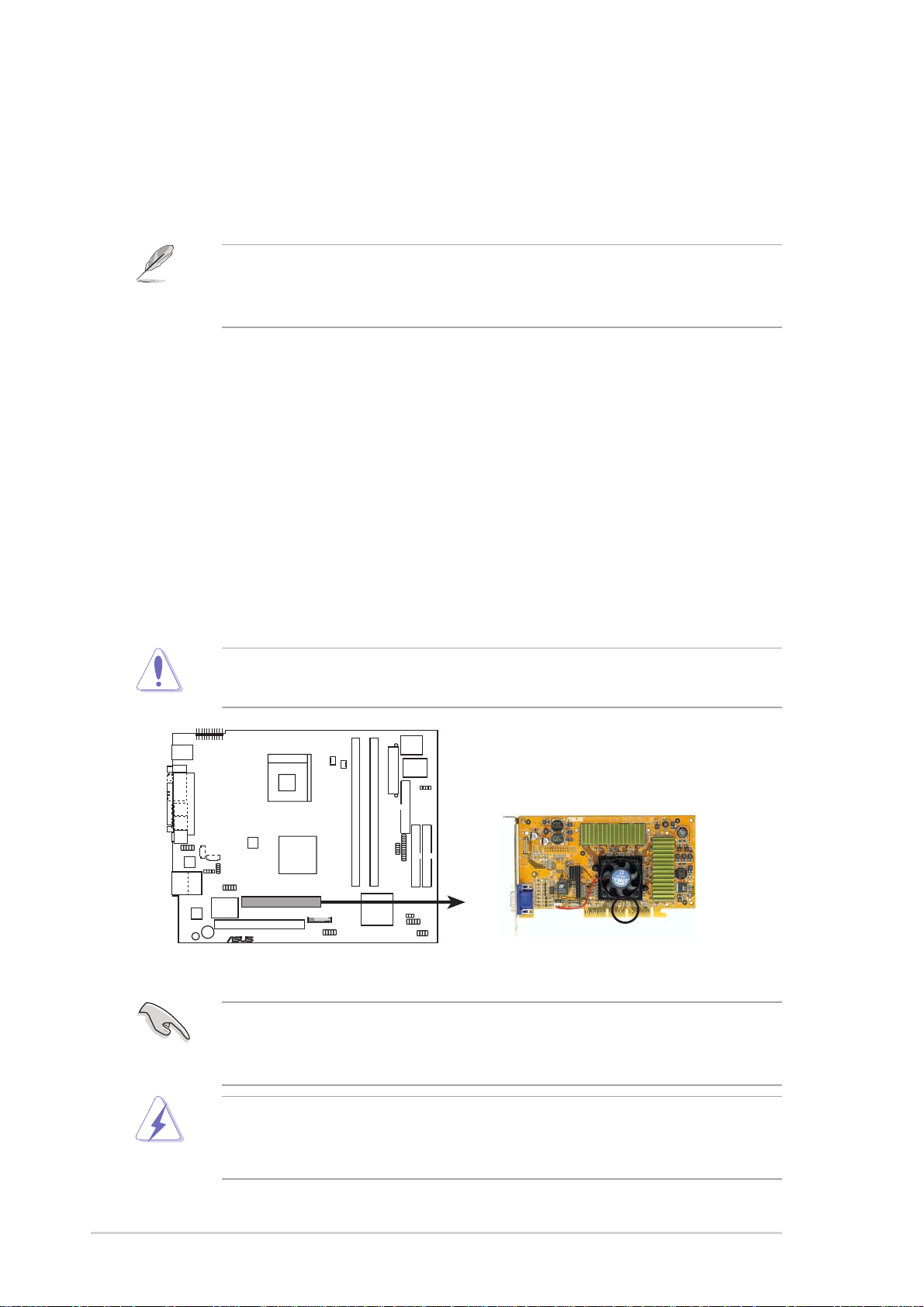
P4R8T
P4R8T Accelerated Graphics Port (AGP)
Keyed for 1.5v
If installing the ATi 9500 or 9700 Pro Series VGA cards, use only the
card version PN xxx-xxxxx-30 or later, for optimum performance and
overclocking stability.
Unplug the power cord before adding or removing expansion cards.
Failure to do so can cause you physical injury and damage the
motherboard.
30
Chapter 2: Basic installation
 Loading...