

Page 1

Page 2

VPN ADSL Router
®
SL6000/SL6300
User’s Manual
Page 3

Copyright Information
No part of this manual, including the products and software described in it,
may be reproduced, transmitted, transcribed, stored in a retrieval system, or
translated into any language in any form or by any means, except documentation
kept by the purchaser for backup purposes, without the express written
permission of ASUSTeK COMPUTER INC. (“ASUS”).
ASUS PROVIDES THIS MANUAL “AS IS” WITHOUT WARRANTY OF
ANY KIND, EITHER EXPRESS OR IMPLIED, INCLUDING BUT NOT
LIMITED TO THE IMPLIED WARRANTIES OR CONDITIONS OF
MERCHANT ABILITY OR FITNESS FOR A P AR TICULAR PURPOSE. IN
NO EVENT SHALL ASUS, ITS DIRECTORS, OFFICERS, EMPLOYEES
OR AGENTS BE LIABLE FOR ANY INDIRECT , SPECIAL, INCIDENT AL,
OR CONSEQUENTIAL DAMAGES (INCLUDING DAMAGES FOR LOSS
OF PROFITS, LOSS OF BUSINESS, LOSS OF USE OR DATA,
INTERRUPTION OF BUSINESS AND THE LIKE), EVEN IF ASUS HAS
BEEN ADVISED OF THE POSSIBILITY OF SUCH DAMAGES ARISING
FROM ANY DEFECT OR ERROR IN THIS MANUAL OR PRODUCT.
Product warranty or service will not be extended if: (1) the product is repaired,
modified or altered, unless such repair, modification of alteration is authorized
in writing by ASUS; or (2) the serial number of the product is defaced or
missing.
Products and corporate names appearing in this manual may or may not be
registered trademarks or copyrights of their respective companies, and are used
only for identification or explanation and to the owners’ benefit, without intent
to infringe.
SPECIFICATIONS AND INFORMATION CONTAINED IN THIS
MANUAL ARE FURNISHED FOR INFORMATIONAL USE ONLY, AND
ARE SUBJECT TO CHANGE AT ANY TIME WITHOUT NOTICE, AND
SHOULD NOT BE CONSTRUED AS A COMMITMENT BY ASUS. ASUS
ASSUMES NO RESPONSIBILITY OR LIABILITY FOR ANY ERRORS
OR INACCURACIES THAT MAY APPEAR IN THIS MANUAL,
INCLUDING THE PRODUCTS AND SOFTWARE DESCRIBED IN IT.
Copyright © 2003 ASUSTeK COMPUTER INC. All Rights Reserved.
Product Name: ASUS VPN ADSL Router (SL6000/SL6300)
Manual Revision: 1 E1428
Release Date: October 2003
2 ASUS VPN ADSL Router
Page 4

Copyright Information
ASUSTeK COMPUTER INC. (Asia-Pacific)
Address: 150 Li-Te Road, Peitou, Taipei, Taiwan 112
General Tel: +886-2-2894-3447
General Fax: +886-2-2894-3449
Web Site: www.asus.com.tw
Technical Support
Networking (Tel): +886-2-2890-7902 (English)
MB/Others (Tel): +886-2-2890-7121 (English)
Notebook (Tel): +886-2-2890-7122 (English)
Desktop/Server (Tel): +886-2-2890-7123 (English)
Support Fax: +886-2-2890-7698
ASUS COMPUTER INTERNATIONAL (America)
Address: 44370 Nobel Drive, Fremont, CA 94538, USA
General Fax: +1-502-933-8713
General Email: tmd1@asus.com
Web Site: usa.asus.com
Technical Support
Support Fax: +1-502-933-8713
General Support: +1-502-995-0883
Notebook Support: +1-510-739-3777 x5110
Support Email: tsd@asus.com
ASUS COMPUTER GmbH (Germany and Austria)
Address: Harkortstr. 25, 40880 Ratingen, BRD, Germany
General Email: sales@asuscom.de (for marketing requests only)
General Fax: +49-2102-9599-31
Web Site: www.asuscom.de
Technical Support
Components: +49-2102-9599-0
Notebook PC: +49-2102-9599-10
Support Fax: +49-2102-9599-11
Support Email: www.asuscom.de/support (for online support)
ASUSTeK COMPUTER (Middle East and North Africa)
Address: P.O. Box 64133, Dubai, U.A.E.
General Tel: +9714-283-1774
General Fax: +9714-283-1775
Web Site: www.ASUSarabia.com
ASUS VPN ADSL Router 3
Page 5

Table of Contents
1. Introduction ............................................................................. 9
1.1 Features .................................................................................... 9
1.2 System Requirements ............................................................... 9
1.3 Using this Document................................................................ 10
1.4 Getting Support ............................................................................. 10
2. Getting to Know SL6000/SL6300 ......................................... 11
2.1 Parts List ....................................................................................... 11
2.2 Front Panel ................................................................................... 11
2.3 Rear Panel .................................................................................... 12
3. Quick Start Guide.................................................................. 13
3.1 Connecting the Hardware .............................................................. 13
3.1.1 Connect the ADSL line .......................................................... 13
3.1.2 Connect the computers or a LAN .......................................... 14
3.1.3 Attach the power adapter ...................................................... 14
3.1.4 T urn on the SL6000/SL6300 and your computers ................. 14
3.2 Configuring Your Computers.......................................................... 15
3.2.1 Before you begin................................................................... 15
3.2.2 Windows® XP PCs: .............................................................. 15
3.2.3 Windows® 2000 PCs:........................................................... 16
3.2.4 Windows® Me PCs............................................................... 17
3.2.5 Windows® 95, 98 PCs: ......................................................... 18
3.2.6 Windows® NT 4.0 workstations: ........................................... 19
3.2.7 Assigning static Internet information to your PCs................... 20
3.3 Quick Configuration of SL6000/SL6300 ......................................... 20
3.3.1 Buttons Used in Setup Wizard .............................................. 21
3.3.2 Setting Up the SL6000/SL6300............................................. 21
3.3.3 Testing Y our Setup................................................................ 31
3.3.4 Default Router Settings ......................................................... 31
4. Starting the Configuration Manager.................................... 31
4.1 Log into Configuration Manager..................................................... 31
4.2 Functional Layout .......................................................................... 32
4.2.1 Setup Menu Navigation T ips ................................................. 32
4.2.2 Commonly Used Buttons and Icons ...................................... 32
4.3 The Home Page of Configuration Manager.................................... 34
4 ASUS VPN ADSL Router
Page 6

Table of Contents
5. System Information .............................................................. 35
6. Configuring LAN Settings .................................................... 36
6.1 LAN IP Address ............................................................................. 36
6.1.1 LAN IP Configuration Parameters ......................................... 36
6.1.2 Configuring the LAN IP Address ............................................ 36
6.2 DHCP (Dynamic Host Configuration Protocol) ............................... 38
6.2.1 What is DHCP? .................................................................... 38
6.2.2 Why use DHCP? .................................................................. 39
6.2.3 Configuring DHCP Server ..................................................... 39
6.2.4 Viewing Current DHCP Address Assignments....................... 40
6.3 DNS .............................................................................................. 40
6.3.1 About DNS............................................................................ 40
6.3.2 Assigning DNS Addresses .................................................... 42
6.3.3 Configuring DNS Relay......................................................... 42
6.4 Viewing LAN Statistics................................................................... 43
7. Configuring WAN/ADSL Settings ........................................ 44
7.1 ADSL Connection .......................................................................... 44
7.2 WAN Configuration........................................................................ 45
7.2.1 MPoA Bridged and PPPoE Relay:......................................... 45
7.2.2 MPoA Routed: ...................................................................... 45
7.2.3 IPoA Routed: ........................................................................ 45
7.2.4 PPPoA Routed and PPPoE Routed: ..................................... 46
7.3 Viewing WAN/ADSL Statistics ....................................................... 47
8. Configuring Routes .............................................................. 48
8.1 Overview of IP Routes................................................................... 48
8.1.1 Do I need to define IP routes?............................................... 48
8.2 DNS Relay Configuration .............................................................. 49
8.3 Static Routing................................................................................ 49
8.3.1 Static Route Configuration Parameters ................................. 49
8.3.2 Adding Static Routes............................................................. 50
8.3.3 Modifying Static Routes ........................................................ 50
8.3.4 Deleting Static Routes .......................................................... 51
8.3.5 Viewing the Static Routing Table ........................................... 51
ASUS VPN ADSL Router 5
Page 7

Table of Contents
9. Configuring Firewall/NAT Settings ...................................... 52
9.1 DoS Protection and Stateful Packet Inspection .............................. 52
9.2 Default ACL Rules ......................................................................... 53
9.3 Configuring Inbound ACL Rules..................................................... 53
9.3.2 Add Inbound ACL Rules ........................................................ 60
9.3.3 Modify Inbound ACL Rules.................................................... 61
9.3.4 Delete Inbound ACL Rules .................................................... 61
9.3.5 Display Inbound ACL Rules .................................................. 61
9.4 Configuring Outbound ACL Rules .................................................. 62
9.4.2 Add an Outbound ACL Rule .................................................. 68
9.4.3 Modify Outbound ACL Rules ................................................. 69
9.4.4 Delete Outbound ACL Rules ................................................. 69
9.4.5 Display Outbound ACL Rules ................................................ 69
9.5 Configuring Group ACL Rules........................................................ 70
9.5.1 Add/Delete a User Group...................................................... 70
9.6 Configuring Self Access Rules....................................................... 72
9.6.1 Add a Self Access Rule ......................................................... 72
9.6.2 View Self Access Summary .................................................. 72
9.6.3 Delete Self Access Rule........................................................ 72
9.7 Configuring Service List................................................................. 73
9.7.1 Options in Service Configuration Page.................................. 74
9.7.2 Add a Service ....................................................................... 74
9.7.3 Modify a Service ................................................................... 74
9.7.4 Delete a Service ................................................................... 75
9.7.5 View Configured Services ..................................................... 75
9.8 DoS (Denial of Service) ................................................................. 76
9.8.1 SYN Flooding Attack Check.................................................. 76
9.8.2 Winnuke Attack Check.......................................................... 76
9.8.3 MIME Flood Attack Check..................................................... 76
9.8.4 Maximum IP Fragment Count ............................................... 77
6 ASUS VPN ADSL Router
Page 8

Table of Contents
9.9 Policy List ...................................................................................... 78
9.9.1 Application Filter ................................................................... 78
9.9.2 NAT Pool .............................................................................. 81
9.9.3 IP Pool.................................................................................. 82
9.9.4 Firewall User......................................................................... 84
9.9.5 Time Range .......................................................................... 86
9.10 Firewall Statistics......................................................................... 88
10.2 Establish VPN Connection Using Automatic Keying..................... 91
10.2.1 VPN Tunnel Configuration Parameters for Automatic Keying91
10.2.2 Add a Rule for VPN Connection Using Preshared Key........ 95
10.2.3 Modify VPN Rules............................................................... 96
10.2.4 Delete VPN Rules............................................................... 97
10.2.5 Display VPN Rules ............................................................. 97
10.3 Establish VPN Connection Using Manual Keys ........................... 97
10.3.1 VPN Tunnel Configuration Parameters - Manual Key.......... 99
10.3.2 Add a Rule for VPN Connection Using Manual Key........... 101
10.3.3 Modify VPN Rules............................................................. 102
10.3.4 Delete VPN Rules............................................................. 103
10.3.5 Display VPN Rules ........................................................... 103
10.4 VPN Statistics ........................................................................... 103
11.System Log.......................................................................... 106
12.System Management .......................................................... 107
12.1 Global Setting Configuration ...................................................... 107
12.2 User Account Management ....................................................... 109
12.3 Modify System Information ........................................................ 109
12.4 Setup T ime Zone....................................................................... 109
12.4.1 Change/View the System T ime Zone ................................ 110
12.5 System Configuration Management............................................111
12.5.1 Reset System Configuration to Default...............................111
12.5.2 Backup System Configuration ............................................111
12.5.3 Restore System Configuration .......................................... 112
12.6 Upgrade Firmware......................................................................113
ASUS VPN ADSL Router 7
Page 9

Table of Contents
13.System Reset ...................................................................... 114
14.Logout Configuration Manager ......................................... 115
A. IP Addresses, Network Masks, & Subnets ....................... 116
A.1 IP Addresses................................................................................116
A.1.1 Structure of an IP address .................................................. 116
A.1.2 Network classes ..................................................................117
A.2 Subnet masks ..............................................................................118
B. Troubleshooting.................................................................. 119
B.1 Recall default configuration by “RESET” button.......................... 122
B.2 Diagnosing Problem using IP Utilities .......................................... 125
B.2.1 ping .................................................................................... 125
B.2.2 nslookup............................................................................. 126
C. Glossary............................................................................... 127
8 ASUS VPN ADSL Router
Page 10

Chapter 1
1. Introduction
Congratulations on becoming the owner of the SL6000/SL6300 VPN ADSL
Router . Your LAN (local area network) will now be able to access the Internet
via SL6000/SL6300’ s ADSL connection.
This User Manual will show you how to set up the SL6000/SL6300 VPN
ADSL Router, and how to customize its configuration to get the most out of
this product.
1.1 Features
• Built-in ADSL modem in SL6000 (G.992.1 Annex A) / SL6300 (G.992.1
Annex B), which offers up to 8Mbps/800Kbps internet surf speed for
Downstream/Upstream, respectively.
• 10/100Base-T Ethernet router to provide Internet connectivity to all
computers on your LAN
Chapter 1
• NAT (Network Address Translation), Firewall, and IPSec VPN functions to provide secure Internet access for your LAN
• Automatic network address assignment through DHCP Server
• Services including IP route and DNS configuration, RIP, and IP performance monitoring
• Configuration program accessible via a web browser, such as Microsoft
Internet Explorer. Note that Netscape is not supported.
1.2 System Requirements
In order to use the SL6000/SL6300 VPN ADSL Router for Internet access,
you must have the following:
• ADSL service subscription from your ISP.
• One or more computers each containing an Ethernet 10Base-T/100BaseT network interface card (NIC).
• (Optional) An Ethernet hub/switch, if you are connecting the device to
more than four computers on an Ethernet network.
• For system configuration using the supplied web-based program: a web
browser such as Internet Explorer v5.5 or later
ASUS VPN ADSL Router 9
Page 11
Chapter 1
Chapter 1
1.3 Using this Document
1.3.1 Notational conventions
• Acronyms are defined the first time they appear in text and in the glos-
• For brevity, the SL6000/SL6300 is referred to as “the router.”
• The terms LAN and network are used interchangeably to refer to a group
1.3.2 Typographical conventions
• Italics are used to identify terms that are defined in the glossary (Ap-
• Boldface type text is used for items you select from menus and drop-
1.3.3 Special messages
This document uses the following icons to call your attention to specific
instructions or explanations.
sary (Appendix C).
of Ethernet-connected computers at one site.
pendix C).
down lists, and text strings you type when prompted by the program.
Notes: Provides clarification or nonessential information on the
current topic.
Definition: Explains terms or acronyms that may be unfamiliar to
many readers. These terms are also included in the Glossary.
W ARNING: Provides messages of high importance, including messages relating to personal safety or system integrity.
1.4 Getting Support
See the contact information on first few pages of this manual.
10 ASUS VPN ADSL Router
Page 12
Chapter 2
2. Getting to Know SL6000/SL6300
2.1 Parts List
In addition to this document, your SL6000/SL6300 should come with the
following:
• SL6000/SL6300 VPN ADSL Router
• Power adapter
• Ethernet cable (RJ-45) “straight-through” type)
• Phone cable (RJ-11)
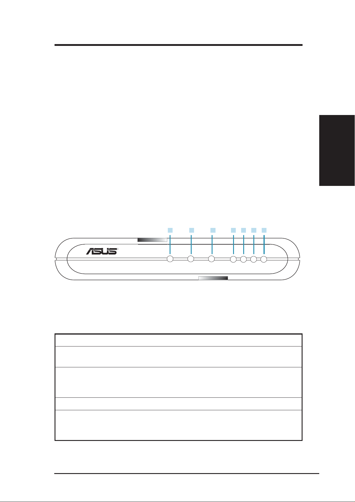
2.2 Front Panel
The front panel contains LED indicators that show the status of the unit.
4 6
5 7
LAN2 LAN3 LAN4
R
VPN ADSL ROUTER
Figure 2.2 Front Panel LEDs
Table 2.1 Front Panel Label and LEDs
1 2 3
POWER STATUS TRAFFIC LAN1
Chapter 2
Label Color Function
POWER green On: Unit is powered on
Off: Unit is powered off
STATUS green On: ADSL link is established and active
Flashing: Trying to create an ADSL connection
Off: No ADSL link
TRAFFIC green Flashing: ADSL data transfer
LAN1-4 green On: LAN link is established
Flashing: Data transfer at LAN connection(s)
Off: No LAN link
ASUS VPN ADSL Router 11
Page 13

Chapter 2
2.3 Rear Panel
The rear panel contains the ports for the unit’ s data and power connections.
Chapter 2
Figure 2.3 Rear Panel Connections
Table 2.2 Rear Panel Labels and Switch/Connectors
1
LINE
2 3 4
P3P4
5
P1P2
6
CONSOLE
7
Reset
8 9
POWER
1. LINE
Connects to your ADSL line. This is a standard RJ-11 telephone jack on
your wall but routed through an ADSL system by your phone company and
may have an optional splitter to allow telephone use on the same line.
2. P1 - P4
Connects to your PC’s Ethernet port, or to the uplink port on your LAN’s hub/
switch, using the provided RJ-45 crossover cable.
3. Console
RJ-45 port for advanced console management. An additional RS232 to
RJ45 cable is required.
4. Reset
Resets the device.
5. Power
Connects to the supplied power adapter.
6. On/Off
Power switch to turn the unit ON and OFF.
12 ASUS VPN ADSL Router
Page 14
Chapter 3
3. Quick Start Guide
This Quick Start Guide provides basic instructions for connecting the SL6000/
SL6300 to a computer or a LAN and to the Internet via ADSL.
• Part 1 provides instructions to set up the hardware.
• Part 2 describes how to configure Internet properties on your
computer(s).
• Part 3 shows you how to configure basic settings on the SL6000/SL6300
to get your LAN connected to the Internet.
After setting up and configuring the device, you can follow the instructions to
verify that it is working properly.
This Quick Start Guide assumes that you have already subscribe ADSL service
with your Internet service provider (ISP). These instructions provide a basic
configuration that should be compatible with your home or small office network
setup. Refer to the subsequent chapters for additional configuration instructions.
3.1 Connecting the Hardware
In 3.1, you should connect the device to an ADSL line, the power outlet, and
your computer or network.
WARNING: Before you begin, turn the power off for all devices.
These include your computer(s), your LAN hub/switch (if applicable),
and the SL6000/SL6300.
For hardware connections, please follow the steps that follow for specific
instructions.
3.1.1 Connect the ADSL line
For SL6000/SL6300: Connect your ADSL line to the port labeled ADSL on
the rear panel of the device. Connect the other end of the line to the wall phone
jack or to the POTS splitter (Optional).
Chapter 3
ASUS VPN ADSL Router 13
Page 15

3.1.2 Connect the computers or a LAN
If your LAN has no more than 4 computers, you can use Ethernet cable to
connect computers directly to the built-in switch on the device. Note that you
should attach one end of the Ethernet cable to any of the port labeled LAN1 -
LAN4 on the rear panel of the device and connect the other end to the Ethernet
port of a computer .
If you LAN has more than 4 computers, you can attach one end of a Ethernet
cable to a hub or a switch (probably an uplink port; please refer to the hub or
switch documentations for instructions) and the other to the Ethernet switch
port (labeled LAN1 - LAN4) on the SL6000/SL6300.
Note that both the crossover or straight-through Ethernet cable can be used to
connect the built-in switch and computers, hubs or switches as the built-in
switch is smart enough to make connections with either type of cables.
Chapter 3
Chapter 3
3.1.3 Attach the power adapter
Connect the AC power adapter to the POWER connector on the back of the
device and plug in the adapter to a wall outlet or a power strip.
3.1.4 Turn on the SL6000/SL6300 and your computers
Press the Power switch on the rear panel of SL6000/SL6300 to the ON position.
Turn on and boot up your computer(s) and any LAN devices such as hubs or
switches. You should verify that its LEDs are illuminated as shown in T able 3.1
Table 3.1 LED Indicators
This LED: ...should be:
POWER Solid green to indicate that the device is turned on. If this light
is not on, check if the power adapter is attached to SL6000/
SL6300 and if it is plugged into a power source.
LAN1 - LAN4 Solid green to indicate that the device can communicate with
your LAN or flashing when the device is sending or receiving
data from your LAN computer(s).
ADSL Solid green to indicate that the device has successfully
established a connection to your ADSL line.
If the LEDs illuminate as expected, SL6000/SL6300 hardware is working
properly .
14 ASUS VPN ADSL Router
Page 16

Chapter 3
3.2 Configuring Your Computers
3.2.1 Before you begin
By default, the SL6000/SL6300 automatically assigns all required Internet
settings to your PCs. You need only to configure the PCs to accept the
information when it is assigned.
Note: In some cases, you may want to assign Internet information
manually to some or all of your computers rather than allow the
SL6000/SL6300 to do so. See “Assigning static Internet information to your PCs” for instructions.
If you have connected your PC of LAN via Ethernet to the SL6000 / SL6300,
follow the instructions that correspond to the operating system installed on
your PC.
3.2.2 Windows® XP PCs:
1. In the W indows task bar , click the Start button, and then click Control
Panel.
2. Double-click the Network Connections icon.
3. In the LAN or High-Speed Internet window, right-click on icon corresponding to your network interface card (NIC) and select Properties.
(Often this icon is labeled Local Area Connection).
The Local Area Connection dialog box displays with a list of currently
installed network items.
4. Ensure that the check box to the left of the item labeled Internet Protocol TCP/IP is checked, and click Properties.
5. In the Internet Protocol (TCP/IP) Properties dialog box, click the radio
button labeled Obtain an IP address automatically. Also click the radio
button labeled Obtain DNS server address automatically.
6. Click OK twice to confirm your changes, and close the Control Panel.
Chapter 3
ASUS VPN ADSL Router 15
Page 17

3.2.3 Windows® 2000 PCs:
First, check for the IP protocol and, if necessary, install it:
1. In the Windows task bar, click the Start button, point to Settings, and
2. Double-click the Network and Dial-up Connections icon.
3. In the Network and Dial-up Connections window , right-click the Local
4. If Internet Protocol (TCP/IP) does not display as an installed compo-
Chapter 3
5. In the Select Network Component Type dialog box, select Protocol,
Chapter 3
then click Control Panel.
Area Connection icon, and then select Properties.
The Local Area Connection Properties dialog box displays with a list of
currently installed network components. If the list includes Internet
Protocol (TCP/IP), then the protocol has already been enabled. Skip to
step 10.
nent, click Install.
and then click Add.
6. Select Internet Protocol (TCP/IP) in the Network Protocols list, and
then click OK.
You may be prompted to install files from your W indows 2000 installa-
tion CD or other media. Follow the instructions to install the files.
7. If prompted, click OK to restart your computer with the new settings.
Next, configure the PCs to accept IP information assigned by the SL6000
/ SL6300:
8. In the Control Panel, double-click the Network and Dial-up Connec-
tions icon.
9. In Network and Dial-up Connections window, right-click the Local Area
Connection icon, and then select Properties.
10.In the Local Area Connection Properties dialog box, select Internet
Protocol (TCP/IP), and then click Properties.
11.In the Internet Protocol (TCP/IP) Properties dialog box, click the radio
button labeled Obtain an IP address automatically. Also click the
radio button labeled Obtain DNS server address automatically.
12.Click OK twice to confirm and save your changes, and then close the
Control Panel.
16 ASUS VPN ADSL Router
Page 18

Chapter 3
3.2.4 Windows® Me PCs
1. In the Windows task bar, click the Start button, point to Settings, and
then click Control Panel.
2. Double-click the Network and Dial-up Connections icon.
3. In the Network and Dial-up Connections window, right-click the Network icon, and then select Properties.
The Network Properties dialog box displays with a list of currently
installed network components. If the list includes Internet Protocol (TCP/
IP), then the protocol has already been enabled. Skip to step 11.
4. If Internet Protocol (TCP/IP) does not display as an installed component, click Add.
5. In the Select Network Component Type dialog box, select Protocol,
and then click Add.
6. Select Microsoft in the Manufacturers box.
7. Select Internet Protocol (TCP/IP) in the Network Protocols list, and
then click OK.
You may be prompted to install files from your Windows Me installation CD or other media. Follow the instructions to install the files.
8. If prompted, click OK to restart your computer with the new settings.
Next, configure the PCs to accept IP information assigned by the SL6000
/ SL6300:
9. In the Control Panel, double-click the Network and Dial-up Connections icon.
10.In Network and Dial-up Connections window , right-click the Network
icon, and then select Properties.
11.In the Network Properties dialog box, select TCP/IP, and then click
Properties.
12.In the TCP/IP Settings dialog box, click the radio button labeled Server
assigned IP address. Also click the radio button labeled Server as-
signed name server address.
Chapter 3
13.Click OK twice to confirm and save your changes, and then close the
Control Panel.
ASUS VPN ADSL Router 17
Page 19

Chapter 3
3.2.5 Windows® 95, 98 PCs:
First, check for the IP protocol and, if necessary, install it:
1. In the Windows task bar, click the Start button, point to Settings, and
then click Control Panel.
2. Double-click the Network icon.
The Network dialog box displays with a list of currently installed net-
work components. If the list includes TCP/IP, and then the protocol has
already been enabled. Skip to step 9.
3. If TCP/IP does not display as an installed component, click Add.
The Select Network Component Type dialog box displays.
4. Select Protocol, and then click Add.
The Select Network Protocol dialog box displays.
Chapter 3
5. Click on Microsoft in the Manufacturers list box, and then click TCP/
6. Click [OK] to return to the Network dialog box, and then click [OK]
7. Click [OK] to restart the PC and complete the TCP/IP installation.
8. Open the Control Panel window, and then click the Network icon.
9. Select the network component labeled TCP/IP, and then click [Proper-
10.In the TCP/IP Properties dialog box, click the IP Address tab.
IP in the Network Protocols list box.
again.
You may be prompted to install files from your W indows 95/98 instal-
lation CD. Follow the instructions to install the files.
Next, configure the PCs to accept IP information assigned by the SL6000
/ SL6300:
ties].
If you have multiple TCP/IP listings, select the listing associated with
your network card or adapter.
11.Click the radio button labeled Obtain an IP address automatically.
12.Click the DNS Configuration tab, and then click the radio button labeled Obtain an IP address automatically.
13.Click [OK] twice to confirm and save your changes.
You will be prompted to restart Windows.
14.Click [Yes].
18 ASUS VPN ADSL Router
Page 20

Chapter 3
3.2.6 Windows® NT 4.0 workstations:
First, check for the IP protocol and, if necessary, install it:
1. In the Windows NT task bar, click the Start button, point to Settings,
and then click Control Panel.
2. In the Control Panel window, double click the Network icon.
3. In the Network dialog box, click the Protocols tab.
The Protocols tab displays a list of currently installed network proto-
cols. If the list includes TCP/IP, then the protocol has already been enabled. Skip to step 9.
4. If TCP/IP does not display as an installed component, click [Add].
5. In the Select Network Protocol dialog box, select TCP/IP, and then click
[OK].
You may be prompted to install files from your Windows NT installation CD or other media. Follow the instructions to install the files.
After all files are installed, a window displays to inform you that a
TCP/IP service called DHCP can be set up to dynamically assign IP
information.
6. Click [Yes] to continue, and then click [OK] if prompted to restart your
computer. Next, configure the PCs to accept IP information assigned
by the SL6000 / SL6300:
7. Open the Control Panel window, and then double-click the Network
icon.
8. In the Network dialog box, click the Protocols tab.
9. In the Protocols tab, select TCP/IP, and then click [Properties].
10.In the Microsoft TCP/IP Properties dialog box, click the radio button
labeled Obtain an IP address from a DHCP server .
11.Click [OK] twice to confirm and save your changes, and then close the
Control Panel.
Chapter 3
ASUS VPN ADSL Router 19
Page 21

Chapter 3
3.2.7 Assigning static Internet information to your PCs
In some cases, you may want to assign Internet information to some or all of
your PCs directly (often called “statically”), rather than allowing the SL6000/
SL6300 to assign it. This option may be desirable (but not required) if:
• You have obtained one or more public IP addresses that you want to
always associate with specific computers (for example, if you are using
a computer as a public web server).
• You maintain different subnets on your LAN.
Before you begin, contact your ISP if you do not already have the following
information:
• The IP address and subnet mask to be assigned to each PC to which you
will be assigning static IP information.
Chapter 3
• The IP address of the default gateway for your LAN. In most cases, this
• The IP address of your ISP’s Domain Name System (DNS) server.
On each PC to which you want to assign static information, follow the
instructions on previous pages relating only to checking for and/or installing
the IP protocol. Once it is installed, continue to follow the instructions for
displaying each of the Internet Protocol (TCP/IP) properties. Instead of enabling
dynamic assignment of the IP addresses for the computer, DNS server, and
default gateway , click the radio buttons that enable you to enter the information
manually.
Note: Y our PCs must have IP addresses that place them in the same
subnet as the SL6000/SL6300’s LAN port. If you manually assign IP
information to all your LAN PCs, you can follow the instructions in
Chapter 6 to change the LAN port IP address accordingly.
is the address assigned to the LAN port on the SL6000/SL6300. By
default, the LAN port is assigned this IP address: 192.168.1.1. (You
can change this number, or another number can be assigned by your
ISP. See Chapter 6 for more information.)
3.3 Quick Configuration of SL6000/SL6300
In this section, you log into the Configuration Manager on the SL6000/SL6300
and configure basic settings for your Internet connection. Your ISP should
provide you with the necessary information to complete this step. Note the
intent here is to quickly get SL6000/SL6300 up and running, instructions are
concise. You may refer to corresponding chapters for more details.
20 ASUS VPN ADSL Router
Page 22
Chapter 3
3.3.1 Buttons Used in Setup Wizard
The SL6000/SL6300 provides a pre-installed software program called Configuration
Manager that enables you to configure SL6000/SL6300 via your Web browser.
The settings that you are most likely to need to change before using the device are
grouped onto sequence of Configuration pages guided by Setup Wizard. The
following table shows the buttons that you’ll encounter in Setup W izard.
[Next]
Click this button to proceed to the next configuration page. If there are no
changes required in the current configuration page, you can click this button
to proceed to the next configuration page.
[Back]
Click this button to go back to the previous configuration page.
3.3.2 Setting Up the SL6000/SL6300
Follow these instructions to setup SL6000/SL6300:
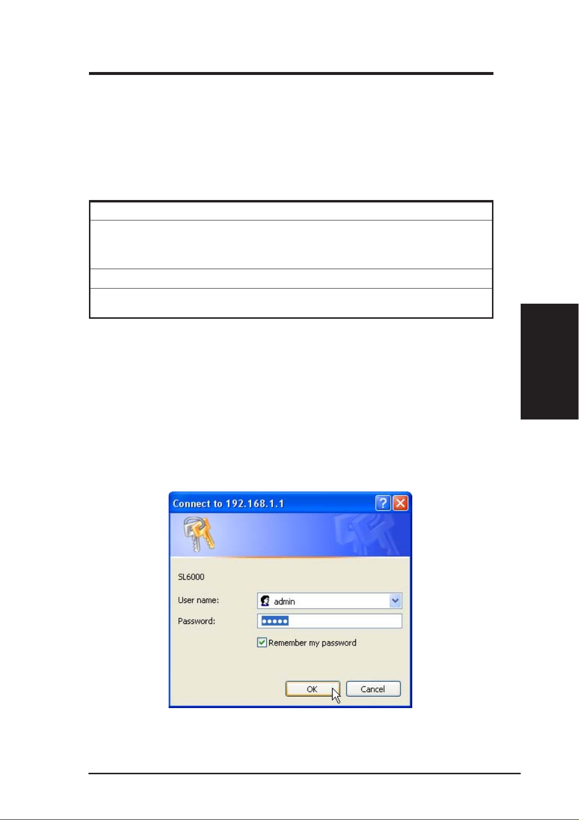
1. At any PC connected to one of the four LAN ports on the SL6000/
SL6300, open your Web browser, and type the following URL in the
address/location box, and press <Enter>: http://192.168.1.1
This is the predefined IP address for the LAN port on the SL6000/
SL6300. A login screen displays, as shown in Figure 3.2
Chapter 3
Figure 3.2 Login Screen
ASUS VPN ADSL Router 21
Page 23
2. Enter your user name and password, and then click [OK] to enter the
Note: You can change the password at any time (see section 12.2
User Account Management).
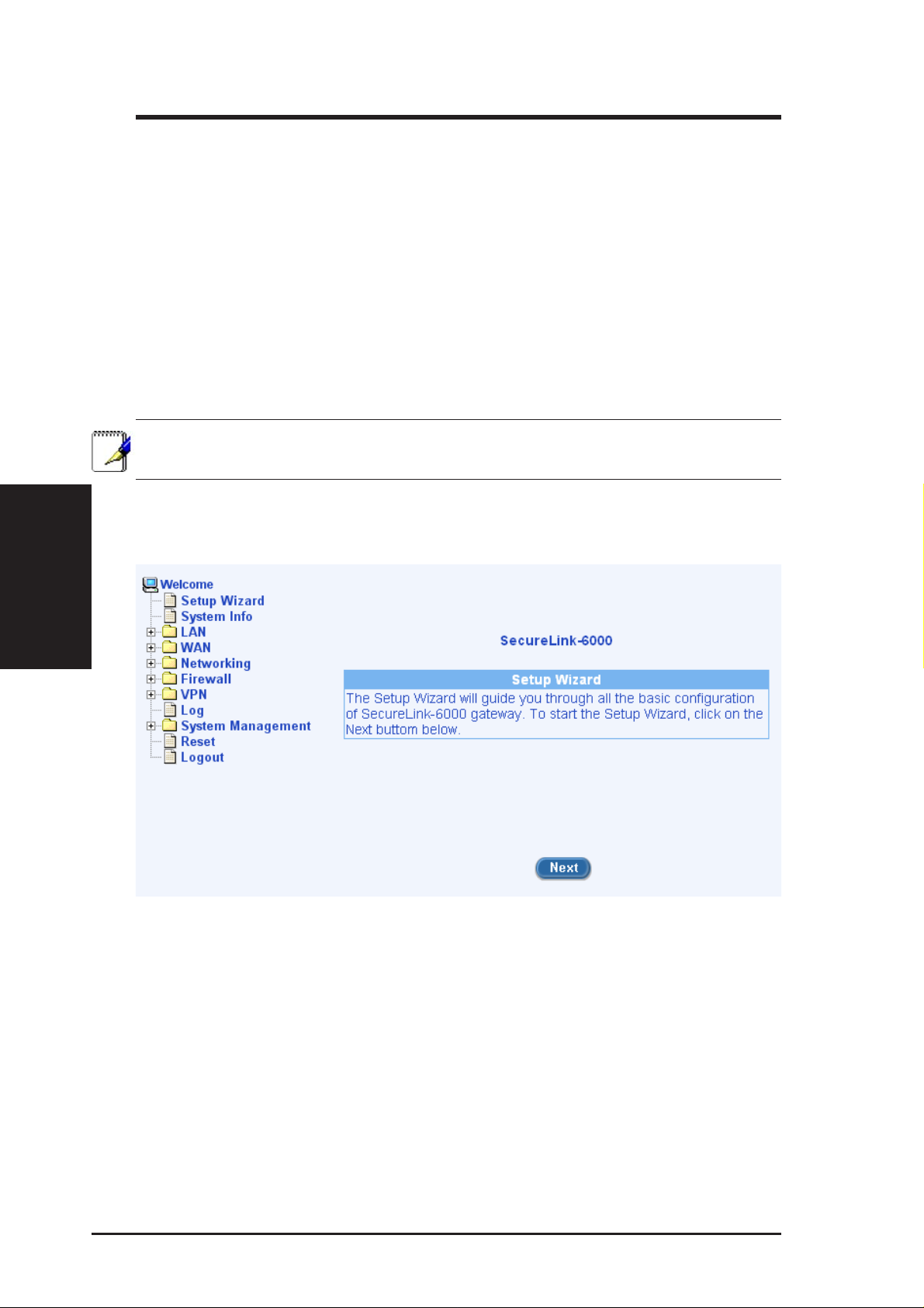
The Setup W izard home page displays each time you log into the Configuration
Chapter 3
Manager (shown in Figure 3.3).
Chapter 3
If you have problem connecting to SL6000/SL6300, you may want to
check if your PC is configured to accept IP address assignment from
SL6000/SL6300. Another method is to set the IP address of your PC to
any IP address in the 192.168.1.0 network, such as 192.168.1.2 but excluding 192.168.1.1 and 192.168.1.255.
Configuration Manager. The first time you log into this program, use
these defaults:
Default User Name: admin
Default Password: admin
Figure 3.3 Setup Wizard Home Page
22 ASUS VPN ADSL Router
Page 24
Chapter 3
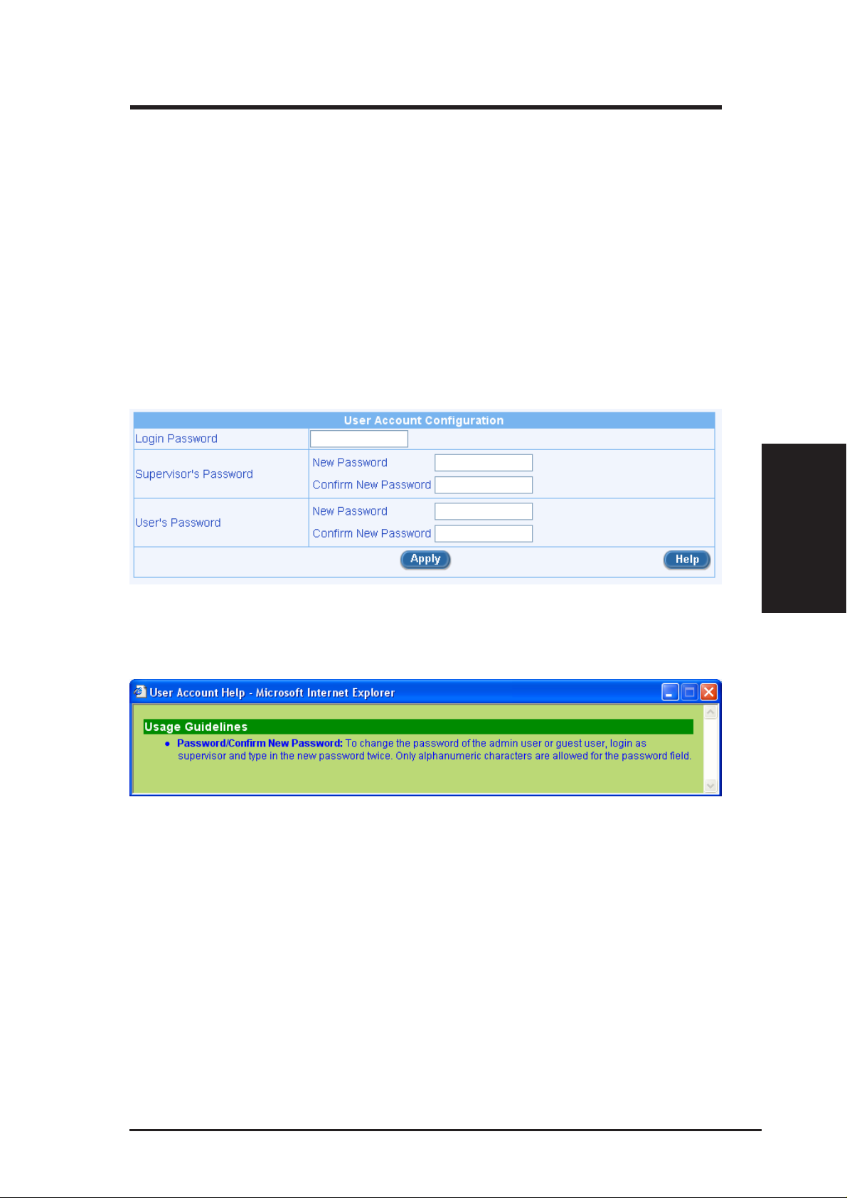
3. Click on the [Next] button to enter the password configuration page as
shown in Figure 3.4. Change the password in the spaces provided if
desired. Otherwise, proceed to the next configuration page by clicking
on the [Next] button.
When changing passwords, make sure you enter the existing login password in
the Login Password field, make any changes for the passwords and click the
[Apply] button to save the changes.
You might get online help from the Setup Wizard by click the [Help] button
and get Figure 3.5.
Figure 3.4 Setup Wizard Password Configuration Page
Figure 3.5 Setup Wizard Password Help Page
Chapter 3
ASUS VPN ADSL Router 23
Page 25
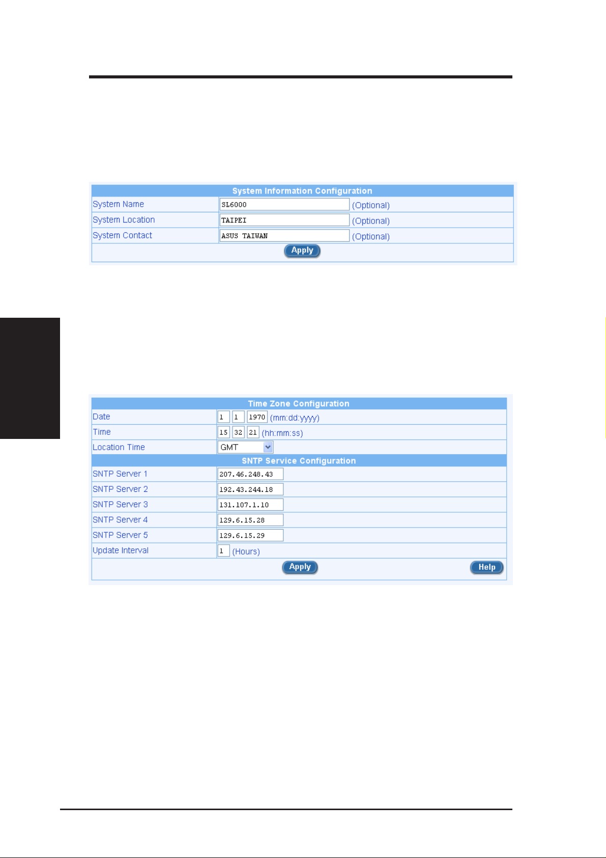
4. Now we are at the System Information setup page; enter the requested
Figure 3.6 Setup Wizard System Identity Configuration Page
5. Set the time zone for SL6000/SL6300 by selecting your time zone from
Chapter 3
Chapter 3
information in the spaces provided and click the [Apply] button to save
the changes. Otherwise, proceed to the next configuration page by clicking on the [Next] button.
the Time Zone drop-down list (shown in Figure 3.7 Time Zone Configuration). Click [Apply] to save the settings and then click on the
[Next] button to go to the next configuration page.
Figure 3.7 Time Zone Configuration
24 ASUS VPN ADSL Router
Page 26
Chapter 3
There is no real time clock inside SL6000/SL6300. The system date and time
are maintained by external network time server via SNTP (Simple Network
Time Protocol). There are five predefined SNTP servers, so you don’ t need to
set the date and time here.
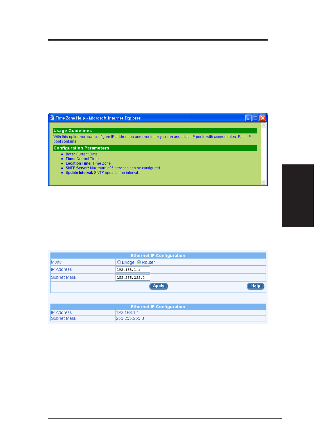
You might get online help from the Setup Wizard by click the [Help] button
and get Figure 3.8.
Figure 3.8 Time Zone Help
6. It is recommended that you keep the default LAN IP settings at this
point until after you have completed the rest of the configurations and
confirm that your Internet connection is working. Click on the [Next]
button to proceed to the next configuration page.
Figure 3.9 Setup Wizard LAN IP Configuration Page
Chapter 3
ASUS VPN ADSL Router 25
Page 27
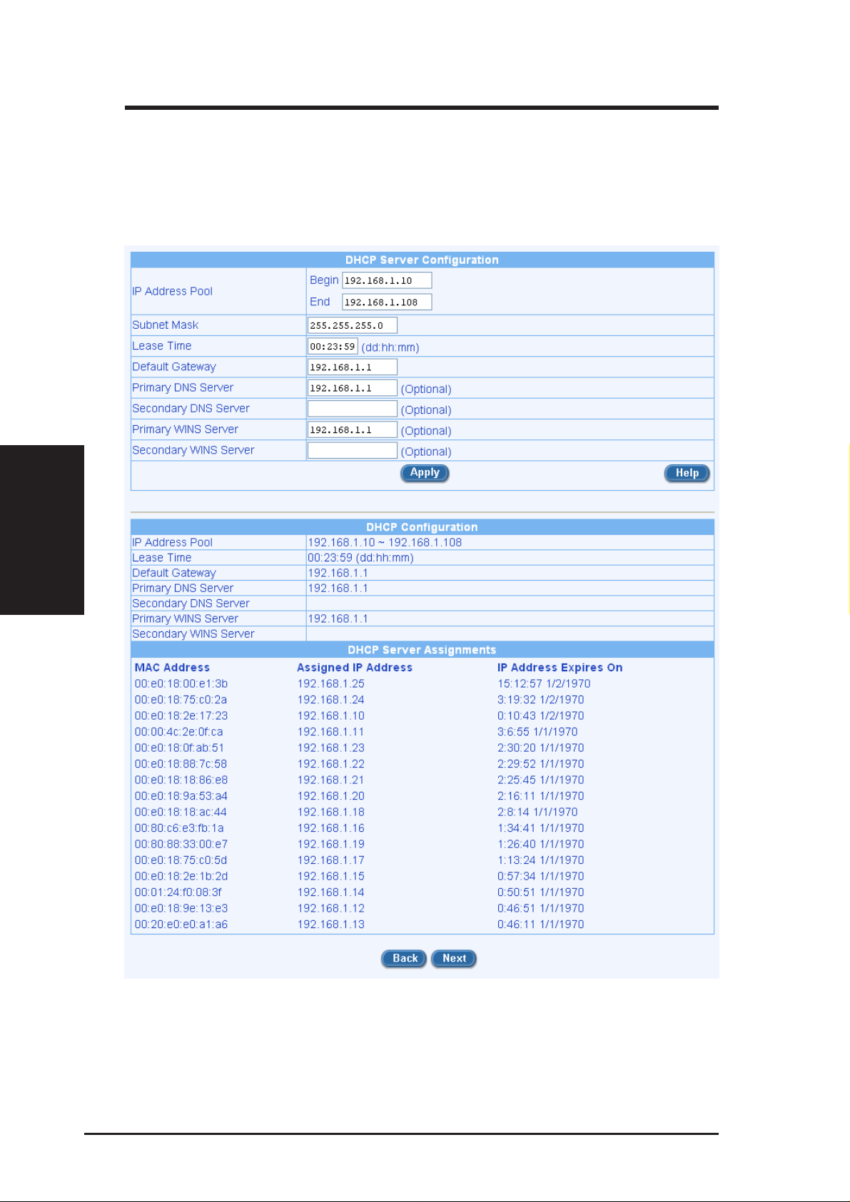
7. It is recommended that you keep the default settings for DHCP server
Chapter 3
Chapter 3
until after you have completed the rest of the configurations and confirm that your Internet connection is working. Click on the [Next] button to proceed to the next configuration page.
Figure 3.10 Setup Wizard DHCP Server Configuration Page
26 ASUS VPN ADSL Router
Page 28
Chapter 3
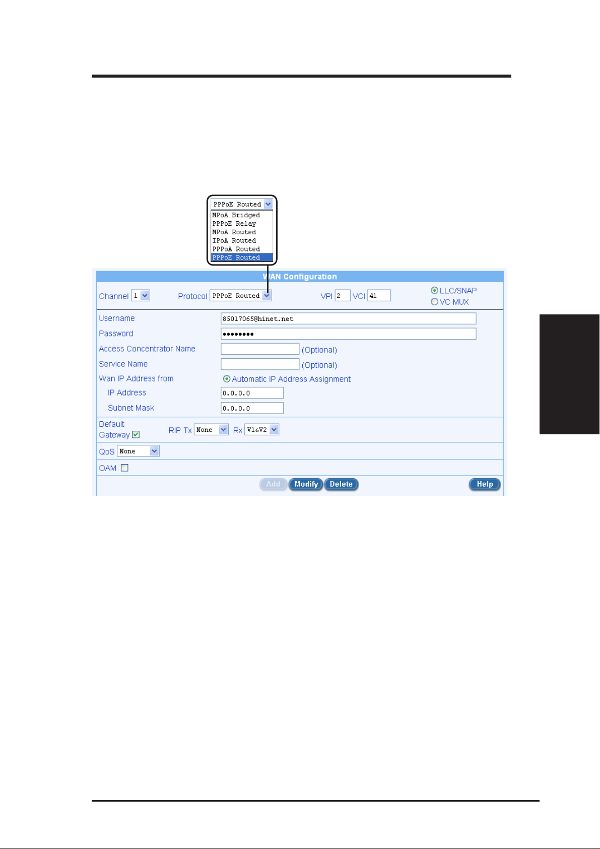
8. Now we are at the last page of the Setup W izard, which is to configure
the WAN settings for SL6000/SL6300. Depending on the connection
mode required from your ISP, you may select from the following connection modes from the Connection Mode drop-down list (see Figure
3.12): MPoA Bridged, PPPoE Relay, MPoA Routed, IPoA Routed,
PPPoA Routed and PPPoE Routed.
Figure 3.12 Setup Wizard WAN Configuration Page
Configuration Parameters
1. Channel: Select the ATM Interface that is to be configured or viewed
2. VPI and VCI: These settings are used to specify the Virtual Path Identifier (VPI) and Virtual Channel Identifier (VCI) that is used for connecting the Broadband Gateway to the ISP’s ATM Switch using the
specified ATM Interface.
• VPI: Enter the VPI of the ATM Connection to the ISP’s ATM Switch
• VCI: Enter the VCI of the ATM Connection to the ISP’s ATM Switch
Chapter 3
3. Select the option VC Mux to carry your Internet Service without encapsulation over the ATM Interface, else select the option LLC - contact your ISP for details
ASUS VPN ADSL Router 27
Page 29

Chapter 3
4. Default Gateway: Select this channel as default gateway of the Broadband Gateway
5. RIP Tx/Rx: Select send/accept routing updates on the channel via RIPv1
or RIPv2, this setting will only be effective if RIP is enabled in Global
Setting page
6. QoS: These settings are used to specify the service category and traffic
parameters that are to be applied for traffic over the specified ATM
interface. Choose one of the following options depending on your traffic requirements.
• None: The traffic carried over this interface will be on a best effort
basis without any guarantee of quality-of-service
• CBR: The quality-of-service applied to traffic over this interface is
that applied to Constant-Bit-Rate (CBR) traffic.
Chapter 3
ATM Service Configuration Parameters
a) MPoA Bridged and PPPoE Relay:
b) MPoA Routed:
• VBR-rt: The quality-of-service applied to traffic over this interface
is that applied to Real-Time-Variable-Bit-Rate (VBR-rt) traffic.
• VBR-nrt: The quality-of-service applied to traffic over this interface is
that applied to Non-Real-Time-Variable-Bit-Rate (VBR-nrt) traffic.
• UBR: The quality-of-service applied to traffic over this interface is
that applied to Unspecified-Bit-Rate (UBR) traffic
* No further configuration parameters need to be specified for MpoA
Bridged and PPPoE Relay services.
* DHCP IP Address Assignment: Select this option if the MPoA Routed
Service interface is to obtain its IP address from your ISP via DHCP.
* Static IP Address Assignment: Select this option if the MPoA Routed
Service interface is to have its IP address configured statically.
* IP Address: Enter the MPoA Routed service interface’s IP Address.
Contact your ISP for details
* Subnet Mask: Enter the MPoA Routed service interface’s Subnet
Mask. Contact your ISP for details
c) IPoA Routed
28 ASUS VPN ADSL Router
Page 30

Chapter 3
* DHCP IP Address Assignment: Select this option if the IPoA Ser-
vice interface is to obtain its IP address from your ISP via DHCP.
* Static IP Address Assignment: Select this option if the IPoA Service
interface is to have its or remote host’ s IP addresses configured statically.
* IP Address: Enter the IPoA service interface’s IP Address. Contact
your ISP for details.
* Subnet Mask: Enter the IPoA service interface’ s Subnet Mask. Con-
tact your ISP for details.
d) PPPoA Routed and PPPoE Routed
* User Name: The user name for setting up the PPPoA/PPPoE Ser-
vice. Contact your ISP for the specific user name to be used.
* Password: The password for setting up the PPPoA/PPPoE Service.
Contact your ISP for the specific password to be used for initial
setup.
e) Bridge IP Settings: These settings must be specified if any LAN inter-
face is in bridge mode, or if any ATM interface carries bridged services
(MPoA Bridge, PPPoE Relay) - the Broadband Gateway software will
automatically prompt you for the bridge interface settings in this case.
* IP Address: Enter the IP address for the bridge interface
* Subnet Mask Address: Enter the Subnet Mask for the bridge inter-
face
Y ou are now finished customizing basic settings. Read the following section to
determine if you have access to the Internet.
Notes:
• If you specify a new service using an ATM interface that has an existing service, the Broadband Gateway software will automatically delete
the existing service and replace it with the new service
• If you change your PPPoA/PPPoE password through your ISP, you need
to set the new password for the configured PPPoA/PPPoE service, in
order to setup the service successfully
Chapter 3
• The Bridge IP Settings are the same for all Interfaces that are in bridge
mode or that have bridge services running over them
• RIP Rx is always enabled as RIP is enabled
ASUS VPN ADSL Router 29
Page 31

3.3.3 Testing Your Setup
At this point, SL6000/SL6300 should enable any computer on your LAN to
use the SL6000/SL6300’ s ADSL connection to access the Internet.
To test the Internet connection, open your web browser, and type the URL of
any external website (such as http://www.yahoo.com). You should be able to
surf the Internet from now on.
If the LEDs do not illuminate as expected or the web page does not display , see
Appendix B for troubleshooting suggestions.
3.3.4 Default Router Settings
In addition to handling the DSL connection to your ISP, the SL6000/SL6300
VPN ADSL Router can provide a variety of services to your network. The
device is pre-configured with default settings for use with a typical home or
Chapter 3
small office network.
Chapter 3
Table 3.2 lists some of the most important default settings; these and other
features are described fully in the subsequent chapters. If you are familiar with
network configuration, review the settings in T able 3.2 to verify that they meet
the needs of your network. Follow the instructions to change them if necessary .
If you are unfamiliar with these settings, try using the device without
modification, or contact your ISP for assistance.
Before you modifying any settings, review Chapter 4 for general information
about accessing and using the Configuration Manager program. We strongly
recommend that you contact your ISP prior to changing the default configuration.
Table 3.2 Default Settings Summary
DHCP (Dynamic Host Configuration Protocol)
Default: DHCP server enabled with the following pool of addresses:
192.168.1.10 through 192.168.1.108
SL6000/SL6300 maintains a pool of private IP addresses for dynamic
assignment to your LAN computers. To use this service, you must have set up
your computers to accept IP information dynamically, as described in Part 2 of
the Quick Start Guide. See section 6.2 for an explanation of the DHCP service.
LAN Port IP Address
Default: Static IP addr ess: 192.168.1.1 Subnet mask: 255.255.255.0
This is the IP address of the LAN port on SL6000/SL6300. The LAN port
connects the device to your Ethernet network. Typically, you will not need to
change this address. See section 6.1 LAN IP Address for instructions.
30 ASUS VPN ADSL Router
Page 32

Chapter 4
4. Starting the Configuration Manager
The SL6000/SL6300 includes a pre-installed program called the Configuration
Manager, which provides an interface to the software installed on the device. It
enables you to configure the device settings to meet the needs of your network.
Y ou access it through your web browser from any PC connected to the SL6000/
SL6300 via the LAN ports.
This chapter describes the general guides for using the Configuration Manager .
4.1 Log into Configuration Manager
The Configuration Manager program is pre-installed on the SL6000/SL6300.
To access the program, you need the following:
A computer connected to the LAN port of SL6000/SL6300 as described in the
Quick Start Guide chapter .
A web browser installed on the computer. The program is designed to work
best with Microsoft Internet Explorer
is not supported.
1. From a LAN computer, open your web browser, type the following in
the web address (or location) box, and press <Enter>:
http://192.168.1.1
This is the predefined IP address for the LAN port on the SL6000/
SL6300. A login screen displays, as shown in Figure 4.1.
®
5.5, or later versions. Note that Netscape
Chapter 4
Figure 4.1 Configuration Manager Login Screen
ASUS VPN ADSL Router 31
Page 33

Chapter 4
2. Enter your user name and password, and then click .
The first time you log into the program, use these defaults:
Default User Name: admin
Default Password: admin
Note: You can change the password at any time (see section 12.2
User Account Management).
The Setup W izard page displays each time you log into the program (shown in
Figure 4.3).
4.2 Functional Layout
T ypical Configuration Manager page consists of two separate frames. The left
frame, as shown in Figure 4.2, contains all the menus available for device
configuration. Menus are indicated by file icons,
grouped into categories, such as LAN, WAN and etc., and indicated by folder
icons,
not. You can click on any of these to display a specific configuration page.
Chapter 4
Setup Menu Frame
, and related menus are
or, depending on whether the group of menus are expanded or
Configuration Frame
Figure 4.2 Typical Configuration Manager Page
A separate page displays in the right-hand-side frame for each menu. For
example, the configuration page displayed in Figure 4.2 is intended for DHCP
configuration.
32 ASUS VPN ADSL Router
Page 34

Chapter 4
4.2.1 Setup Menu Navigation Tips
• To expand a group of related menus: click on the + sign next to the
corresponding file folder icon,
• To contract a group of related menus: click on the - sign next to the
“opened” file folder icon,
• To open a specific configuration page, click on the file icons,
.
, next
to the desired menu item.
4.2.2 Commonly Used Buttons and Icons
The following buttons or icons are used throughout the application. The
following table describes the function for each button or icon.
Table 4.1 Description of Commonly Used Buttons and Icons
[Apply]
Stores any changes you have made on the current page.
[Add]
Adds a new configuration to the system, e.g. a static route or a firewall ACL
rule and etc.
[Modify]
Modifies the existing configuration in the system, e.g. a static route or a
firewall ACL rule and etc.
[Delete]
Deletes the selected item, e.g. a static route or a firewall ACL rule and etc.
[Help]
Launches the online help for the current topic in a separate browser window.
Help is available from any main topic page.
[Refresh]
Re-displays the current page with updated statistics or settings.
[ ]
Selects the item for editing.
[ ]
Deletes the selected item.
Chapter 4
ASUS VPN ADSL Router 33
Page 35

Chapter 4
4.3 The Home Page of Configuration Manager
The Setup Wizard page displays when you first access the Configuration
Manager .
Chapter 4
Figure 4.3 Setup Wizard Page
34 ASUS VPN ADSL Router
Page 36

Chapter 5
5. System Information
This chapter describes your SL6000/SL6300 system information and
configuration summary when you click the “System Info” in the left column.
You may get all information as shown in Figure 5.1.
Figure 5.1. LAN IP Address Configuration Page
Chapter 5
ASUS VPN ADSL Router 35
Page 37

Chapter 6
6. Configuring LAN Settings
This chapter describes how to configure LAN properties for the LAN interface
on the SL6000/SL6300 that communicates with your LAN computers. You’ll
learn to configure IP address, DHCP and DNS server for your LAN in this
chapter .
6.1 LAN IP Address
If you are using the SL6000/SL6300 with multiple PCs on your LAN, you
must connect the LAN via the Ethernet ports on the built-in Ethernet switch.
Y ou must assign a unique IP address to each device residing on your LAN. The
LAN IP address identifies the SL6000/SL6300 as a node on your network; that
is, its IP address must be in the same subnet as the PCs on your LAN. The
default LAN IP for SL6000/SL6300 is 192.168.1.1.
Definition: A network node can be thought of as any interface where
a device connects to the network, such as the SL6000/SL6300’s
LAN port and the network interface cards on your PCs. See Appendix A for an explanation of subnets.
You can change the default to reflect the set of IP addresses that you want to
use with your network.
Note: The SL6000/SL6300 itself can function as a DHCP server for
your LAN computers, as described in section 6.2.3 Configuring
DHCP Server, but not for its own LAN port.
Chapter 6
36 ASUS VPN ADSL Router
Page 38

Chapter 6
6.1.1 LAN IP Configuration Parameters
Table 6.1 describes the configuration parameters available for LAN IP
configuration.
Table 6.1 LAN IP Configuration Parameters
IP Address
The LAN IP address of SL6000/SL6300. This IP is used by your computers
to identify SL6000/SL6300’s LAN port. Note that the public IP address
assigned to you by your ISP is not your LAN IP address. The public IP
address identifies the WAN port on SL6000/SL6300 to the Internet.
Subnet Mask
The LAN subnet mask identifies which parts of the LAN IP Address refer to
your network as a whole and which parts refer specifically to nodes on the
network. Your device is pre-configured with a default subnet mask of
255.255.255.0.
6.1.2 Configuring the LAN IP Address
Follow these steps to change the default LAN IP address.
1. Log into Configuration Manager as administrator, and then click the
LAN menu.
When the sub-menus of the LAN Configuration displays, click Ethernet
submenu to display the IP Address configuration page as shown in Figure 6.1.
Figure 6.1 LAN IP Address Configuration Page
ASUS VPN ADSL Router 37
Chapter 6
Page 39

Chapter 6
2. Enter a LAN IP address and subnet mask for SL6000/SL6300 in the
space provided.
3. Click [Apply] to save the LAN IP address.
If you were using an Ethernet connection for the current session, and
changed the IP address, the connection will be terminated.
4. Reconfigure your PCs, if necessary, so that their IP addresses place
them in the same subnet as the new IP address of the LAN port. See the
Quick Start Guide chapter, “Configuring Your Computers,” for instructions.
5. Log into Configuration Manager by typing the new IP address in your
Web browser’s address/location box.
6.2 DHCP (Dynamic Host Configuration Protocol)
6.2.1 What is DHCP?
DHCP is a protocol that enables network administrators to centrally manage
the assignment and distribution of IP information to computers on a network.
When you enable DHCP on a network, you allow a device - such as the SL6000/
SL6300 - to assign temporary IP addresses to your computers whenever they
connect to your network. The assigning device is called a DHCP server, and
the receiving device is a DHCP client.
Note: If you followed the Quick Start Guide instructions, you either
configured each LAN PC with an IP address, or you specified that it
will receive IP information dynamically (automatically). If you chose
to have the information assigned dynamically , then you configured
your PCs as DHCP clients that will accept IP addresses assigned
from a DHCP server such as SL6000/SL6300.
The DHCP server draws from a defined pool of IP addresses and “leases” them
for a specified amount of time to your computers when they request an Internet
session. It monitors, collects, and redistributes the addresses as needed.
On a DHCP-enabled network, the IP information is assigned dynamically rather
than statically. A DHCP client can be assigned a different address from the
Chapter 6
pool each time it reconnects to the network.
38 ASUS VPN ADSL Router
Page 40

Chapter 6
6.2.2 Why use DHCP?
DHCP allows you to manage and distribute IP addresses throughout your
network from SL6000/SL6300. W ithout DHCP, you would have to configure
each computer separately with IP address and related information. DHCP is
commonly used with large networks and those that are frequently expanded or
otherwise updated.
6.2.3 Configuring DHCP Server
Note: By default, SL6000/SL6300 is configured as a DHCP server on
the LAN side, with a predefined IP address pool of 192.168.1.10
through 192.168.1.108 (subnet mask 255.255.255.0). To change this
range of addresses, follow the procedures described in this section.
First, you must configure your PCs to accept DHCP information assigned by a
DHCP server:
1. Log into Configuration Manager as administrator, click the LAN menu, and then click the
DHCP submenu.
The DHCP Configuration page displays as shown in Figure 6.2:
Figure 6.2 DHCP Configuration Page
ASUS VPN ADSL Router 39
Chapter 6
Page 41

Chapter 6
2. To add an IP address pool, click [Add].
The DHCP Server Pool - Add page displays.
3. Enter the Start IP Address, End IP Address, Net Mask, and Default Gateway
IP Address, fields are required; the others, such as DNS Server IP Address
and WINS Server IP Address are optional. However, it is recommended that
you enter DNS server IP address in the space provided. You may enter the
LAN IP or your ISP’s DNS IP in the DNS Server IP Address field. The
following table describes the DHCP configuration parameters in detail.
Table 6.2 DHCP Configuration Parameters
IP Address Pool Begin/End
Specify the lowest and highest addresses in the DHCP address pool.
Lease Time
The amount of time the assigned address will be used by a device
connected on the LAN.
Default Gateway IP Address
The address of the default gateway for computers that receive IP addresses
from this pool. The default gateway is the IP address that the computers first
contact to communicate with the Internet. Typically, it is SL6000/SL6300’s
LAN port IP address.
DNS Server IP Address
The IP address of the Domain Name System server to be used by computers
that receive IP addresses from this pool. The DNS server translates common
Internet names that you type into your web browser into their equivalent
numeric IP addresses. Typically, the server(s) are located with your ISP.
However, you may enter LAN IP address here as SL6000/SL6300 will serve
as DNS proxy for the LAN computers and forward the DNS request from the
LAN to DNS servers and relay the results back to the LAN computers.
WINS Server IP Address (optional)
The WINS server IP address to be used by computers that receive IP
addresses from the DHCP IP address pool. You don’t need to enter this
information unless your network has a WINS server.
Chapter 6
4. Click [Apply] to save the DHCP server configurations.
NOTE: If you change the LAN IP address and subnet mask, the DHCP
Server Pool will be automatically configured to fall into the same
subnet as the new LAN IP address.
40 ASUS VPN ADSL Router
Page 42

Chapter 6
6.2.4 Viewing Current DHCP Address Assignments
When the SL6000/SL6300 functions as a DHCP server for your LAN, it keeps
a record of any addresses it has leased to your computers. T o view a table of all
current IP address assignments, just go to the DHCP Server Configuration
page. A page displays similar to that shown in Figure 6.2; the lower half of the
same page shows the existing DHCP address assignments.
The DHCP Server Address T able lists any IP addresses that are currently leased
to LAN devices. For each leased address, the table lists the following
information:
Table 6.3 DHCP Address Assignment
MAC Address
A hardware ID of the device that leases an IP address from the DHCP
server.
Assigned IP Address
The address that has been leased from the pool.
IP Address Expired on
The time when the leased address is to be terminated.
6.3 DNS
6.3.1 About DNS
Domain Name System (DNS) servers map the user-friendly domain names
that users type into their Web browsers (e.g., “yahoo.com”) to the equivalent
numerical IP addresses that are used for Internet routing.
When a PC user types a domain name into a browser, the PC must first send a
request to a DNS server to obtain the equivalent IP address. The DNS server
will attempt to look up the domain name in its own database, and will
communicate with higher-level DNS servers when the name cannot be found
locally. When the address is found, it is sent back to the requesting PC and is
referenced in IP packets for the remainder of the communication.
ASUS VPN ADSL Router 41
Chapter 6
Page 43

Chapter 6
6.3.2 Assigning DNS Addresses
Multiple DNS addresses are useful to provide alternatives when one of the
servers is down or is encountering heavy traffic. ISPs typically provide primary
and secondary DNS addresses, and may provide additional addresses. Your
LAN PCs learn these DNS addresses in one of the following ways:
Statically: If your ISP provides you with their DNS server addresses, you can
assign them to each PC by modifying the PCs’ IP properties.
Dynamically from a DHCP pool: Y ou can configure the DHCP Server SL6000/
SL6300 and create an address pool that specify the DNS addresses to be
distributed to the PCs. Refer to the section Configuring DHCP Server for
instructions on creating DHCP address pools.
In either case, you can specify the actual addresses of the ISP’s DNS servers
(on the PC or in the DHCP pool), or you can specify the address of the LAN
port on the VPN ADSL Router (e.g., 192.168.1.1). When you specify the LAN
port IP address, the device performs DNS relay, as described in the following
section.
Note: If you specify the actual DNS addresses on the PCs or in the
DHCP pool, the DNS relay feature is not used.
6.3.3 Configuring DNS Relay
When you specify the device’ s LAN port IP address as the DNS address, then
SL6000/SL6300 automatically performs “DNS relay”; i.e., because the device
itself is not a DNS server, it forwards domain name lookup requests from the
LAN PCs to a DNS server at the ISP. It then relays the DNS server’s response
to the PC.
When performing DNS relay, the SL6000/SL6300 must maintain the IP
addresses of the DNS servers it contacts. It can learn these addresses in either
or both of the following ways:
Follow these steps to configure DNS relay:
1. Enter LAN IP in the DNS Server IP Address field in DHCP configura-
Chapter 6
2. Configure the LAN PCs to use the IP addresses assigned by the DHCP
tion page as shown in Figure 6.2.
server on SL6000/ SL6300, or enter SL6000/SL6300’ s LAN IP address
as their DNS server address manually for each PC on your LAN.
42 ASUS VPN ADSL Router
Page 44

Chapter 6
Note: DNS addresses that are assigned to LAN PCs prior to enabling DNS relay will remain in effect until the PC is rebooted. DNS
relay will only take effect when a PC’s DNS address is the LAN IP
address. Similarly, if after enabling DNS relay, you specify a DNS
address (other than the LAN IP address) in a DHCP pool or statically on a PC, then that address will be used instead of the DNS
relay address.
6.4 Viewing LAN Statistics
You can view statistics of your LAN traffic on SL6000/SL6300. You will not
typically need to view this data, but you may find it helpful when working with
your ISP to diagnose network and Internet data transmission problems.
T o view LAN IP statistics, click “Statistics” on the LAN submenu. Figure 6.3
shows the LAN Statistics page
Figure 6.3 LAN Statistics Page
To display the updated statistics since you opened the page, click [Refresh].
ASUS VPN ADSL Router 43
Chapter 6
Page 45

Chapter 7
Chapter 7
7. Configuring WAN/ADSL Settings
This chapter describes how to configure WAN/ADSL settings for the WAN/
ADSL interface on the SL6000/SL6300 that communicates with your ISP. Y ou’ll
learn how to configure ADSL, IP address, and connection mode for your WAN
in this chapter .
7.1 ADSL Connection
There are several ADSL line configurations available on SL6000 and SL6300,
for Annex A and Annex B, respectively . Figure 7.1 shows the available modes
of SL6000: Multi, G.DMT, G.Lite and ANSI. You may click [Connect] to
create the ADSL connection and click [Disconnect] to end down your ADSL
connection.
The ADSL line status is also shown, no matter it’s activating, connected, or
disconnect (Figure 7.1)
Figure 7.1 ADSL Connection Page
44 ASUS VPN ADSL Router
Page 46

Chapter 7
7.2 WAN Configuration
For WAN port configuration, there are several different protocols supported by
SL6000/SL6300 to match your ISP’s requirement, including MPoA Bridged,
PPPoE Relay , MPoA Routed, IPoA Routed, PPPoA Routed and PPPoE Routed.
7.2.1 MPoA Bridged and PPPoE Relay:
No further configuration parameters need to be specified for MpoA Bridged
and PPPoE Relay services.
7.2.2 MPoA Routed:
* DHCP IP Address Assignment: Select this option if the MPoA Routed
Service interface is to obtain its IP address from your ISP via DHCP.
* Static IP Address Assignment: Select this option if the MPoA Routed
Service interface is to have its IP address configured statically.
Chapter 7
* IP Address: Enter the MPoA Routed service interface’ s IP Address. Con-
tact your ISP for details
* Subnet Mask: Enter the MPoA Routed service interface’ s Subnet Mask.
Contact your ISP for details.
7.2.3 IPoA Routed:
* DHCP IP Address Assignment: Select this option if the IPoA Routed
Service interface is to obtain its IP address from your ISP via DHCP.
* Static IP Address Assignment: Select this option if the IPoA Routed
Service interface is to have its IP address configured statically.
* IP Address: Enter the IPoA Routed service interface’ s IP Address. Con-
tact your ISP for details
* Subnet Mask: Enter the IPoA Routed service interface’s Subnet Mask.
Contact your ISP for details.
ASUS VPN ADSL Router 45
Page 47

Chapter 7
Chapter 7
7.2.4 PPPoA Routed and PPPoE Routed:
* Username: The user name for setting up the PPPoA/PPPoE Service.
* Password: The password for setting up the PPPoA/PPPoE Service. Con-
* DoD : Dial on Demand. The SL6000/SL6300 attempts to connect to
* Inactivity Timeout: The amount of time that specifies the PPP con-
Contact your ISP for the specific user name to be used.
tact your ISP for the specific password to be used for initial setup.
your ISP when an outgoing traffic is detected.
nection must elapse due to inactivity.
Figure 7.2 WAN Configuration Page
46 ASUS VPN ADSL Router
Page 48

Chapter 7
7.3 Viewing WAN/ADSL Statistics
Y ou can view statistics of your WAN/ADSL traffic. Y ou will not typically need
to view this data, but you may find it helpful when working with your ISP to
diagnose network and Internet data transmission problems.
To view WAN/ADSL statistics, click Statistics on the WAN submenu. Figure
7.3 shows the WAN/ADSL Statistics page.
Chapter 7
Figure 7.3 WAN Statistics Page
T o see the updated statistics since you opened the page, simply click [Refresh].
ASUS VPN ADSL Router 47
Page 49

8. Configuring Routes
Y ou can use Configuration Manager to define specific routes for your Internet
and network data communication. This chapter describes basic routing concepts
and provides instructions for creating routes.
Note that most users do not need to define routes.
Chapter 8
8.1 Overview of IP Routes
The essential challenge of a router is: when it receives data intended for a
particular destination, which next device should it send that data to? When you
define IP routes, you provide the rules that SL6000/SL6300 uses to make these
decisions.
8.1.1 Do I need to define IP routes?
Chapter 8
Most users do not need to define IP routes. On a typical small home or office
LAN, the existing routes that set up the default gateways for your LAN
computers and for the SL6000/SL6300 provide the most appropriate path for
all your Internet traffic.
• On your LAN computers, a default gateway directs all Internet traffic
to the LAN port on the SL6000/SL6300. Your LAN computers know
their default gateway either because you assigned it to them when you
modified their TCP/IP properties, or because you configured them to
receive the information dynamically from a server whenever they access the Internet. (Each of these processes is described in the Quick
Start Guide instructions, Part 2.)
• On the SL6000/SL6300 itself, a default gateway is defined to direct all
outbound Internet traffic to a router at your ISP. This default gateway is
assigned automatically by your ISP whenever the device negotiates an
Internet connection. (The process for adding a default route is described
in section 8.3.2 Adding Static Routes.)
Y ou may need to define routes if your home setup includes two or more networks
or subnets, if you connect to two or more ISP services, or if you connect to a
remote corporate LAN.
48 ASUS VPN ADSL Router
Page 50

Chapter 8
8.2 DNS Relay Configuration
Y ou may input your ISP’ s Primary/Secondary DNS server address here if your
PC’ s DNS server address is directed to SL6000/SL6300, instead of automatically
getting DNS server address from the ISP . Click [Apply] after typing your ISP’ s
Primary/Secondary DNS server address.
Chapter 8
Figure 8.1 DNS Relay Configuration Page
8.3 Static Routing
8.3.1 Static Route Configuration Parameters
The following table defines the available configuration parameters for static
routing configuration.
ASUS VPN ADSL Router 49
Page 51

Table 8.1 Static Route Configuration Parameters
Chapter 8
Chapter 8
Destination IP Address
Specifies the IP address of the destination computer or an entire destination
network. It can also be specified as all zeros to indicate that this route should
be used for all destinations for which no other route is defined (this is the
route that creates the default gateway). Note that destination IP must be a
network ID. The default route uses a destination IP of 0.0.0.0. Refer to
Appendix A for an explanation of network ID.
Destination Subnet
Indicates which parts of the destination address refer to the network and
which parts refer to a computer on the network. Refer to Appendix A, for an
explanation of network masks. The default route uses a netmask of 0.0.0.0.
Gateway IP Address
Gateway IP address
8.3.2 Adding Static Routes
Follow these instructions to add a static route to the routing table.
1. In the Static Routes Configuration page (as shown in Figure 8.2.), enter
static routes information such as destination IP address, Destination
Subnet and Gateway IP address in the corresponding fields.
For a description of these fields, refer to Table 8.1 Static Route Configuration Parameters.
To create a route that defines the default gateway for your LAN, enter
0.0.0.0 in both the Destination IP Address and Destination Subnet fields.
2. Click [Add] to add a new route.
8.3.3 Modifying Static Routes
Follow these instructions to delete a static route from the routing table.
1. In the Static Routes Configuration page (as shown in Figure 8.2.), select the route from the service drop-down list or click on the
the route to be modified in the Static Routing Table.
icon of
2. Click [Modify] to modify the selected route.
50 ASUS VPN ADSL Router
Page 52

Chapter 8
8.3.4 Deleting Static Routes
Follow these instructions to delete a static route from the routing table.
3. In the Static Routes Configuration page (as shown in Figure 8.2), select
the route from the service drop-down list or click on the
route to be deleted in the Static Routing Table.
4. Click [Delete] to delete the selected route.
W ARNING: Do not remove the route for default gateway unless you
know what you are doing. Removing the default route will render
the Internet unreachable.
icon of the
8.3.5 Viewing the Static Routing Table
All IP-enabled computers and routers maintain a table of IP addresses that are
commonly accessed by their users. For each of these destination IP addresses,
the table lists the IP address of the first hop the data should take. This table is
known as the device’ s routing table.
T o view the SL6000/SL6300’s routing table, click the Routing sub menu under
Networking. The Static Routing Table displays in the lower half of the Static
Routing Configuration page, as shown in Figure 8.2:
The Static Routing Table displays a row for each existing route containing the
IP address of the destination network, subnet mask of destination network and
the IP of the gateway that forwards the traffic. This table shows only useradded routes.
Chapter 8
Figure 8.2 Static Routing Configuration Page
ASUS VPN ADSL Router 51
Page 53

Chapter 9
9. Configuring Firewall/NAT Settings
SL6000/SL6300 provides built-in firewall/NAT functions, enabling you to
protect the system against denial of service (DoS) attacks and other types of
malicious accesses to your LAN while providing Internet access sharing at the
same time. You can also specify how to monitor attempted attacks, and who
should be automatically notified.
This chapter describes how to create/modify/delete ACL (Access Control List)
rules to control the data passing through your network. You will use firewall
configuration pages to:
• Create, modify and delete inbound/outbound ACL rules.
• Create, modify and delete predefined services to be used in inbound/
outbound ACL configurations.
Chapter 9
• Create service list (DOS)
• View ACL inbound/outbound rules
• View firewall statistics.
Note: When you define an ACL rule, you instruct the SL6000/SL6300
to examine each data packet it receives to determine whether it
meets criteria set forth in the rule. The criteria can include the network or Internet protocol it is carrying, the direction in which it is
traveling (for example, from the LAN to the Internet or vice versa),
the IP address of the sending computer , the destination IP address,
and other characteristics of the packet data.
If the packet matches the criteria established in a rule, the packet can either be
accepted (forwarded towards its destination), or denied (discarded), depending
on the action specified in the rule.
9.1 DoS Protection and Stateful Packet Inspection
The firewall as implemented in SL6000/SL6300 provides DoS (Denial of
Service) protection and stateful packet inspection as the first line security for
your network. No configuration is required for this protection on your network
as long as firewall is enabled for SL6000/SL6300. By default, the firewall is
enabled at the factory . Please refer to section 12.1 Global Setting Configuration
to enable or disable firewall service on SL6000/SL6300.
52 ASUS VPN ADSL Router
Page 54

Chapter 9
9.2 Default ACL Rules
SL6000/SL6300 supports four types of default access rules:
• Inbound Access Rules: for controlling incoming access to computers on your LAN.
• Outbound Access Rules: for controlling outbound access to external networks for
hosts on your LAN.
• Group Access Rules: for controlling users and user group information on your LAN.
• Self Access Rules: for controlling access privilege to SL6000/SL6300 itself.
Default Inbound Access Rules
No default inbound access rule is configured. That is, all traffic from external
hosts to the internal hosts is denied.
Default Outbound Access Rules
The default outbound access rule allows all the traffic originated from your
LAN to be forwarded to the external network using NAT.
9.3 Configuring Inbound ACL Rules
By creating ACL rules in Inbound ACL configuration page as shown in Figure
9.1, you can control (allow or deny) incoming access to computers on your LAN.
Options in this configuration page allow you to:
• Add a rule, and set parameters for it
• Modify an existing rule
• Delete an existing rule
• View configured ACL rules
Chapter 9
ASUS VPN ADSL Router 53
Page 55

Figure 9.1 Inbound ACL Configuration Page
Chapter 9
Chapter 9
54 ASUS VPN ADSL Router
Page 56

Chapter 9
9.3.1 Options in Inbound ACL Configuration Page
Table 9.1 describes the options available for an inbound ACL rule.
Table 9.1 Options in the Firewall Inbound ACL Configuration Page
ID
Add New
Click on this option to add a new ‘basic’ Firewall rule.
Rule Number
Select a rule from the drop-down list, to modify its attributes.
Action
Allow
Select this button to configure the rule as an allow rule.
This rule when bound to the Firewall will allow matching packets to pass
through.
Deny
Select this button to configure the rule as a deny rule.
This rule when bound to the Firewall will not allow matching packets to pass
through.
Move to
This option allows you to set a priority for this rule. The SL6000/SL6300
Firewall acts on packets based on the priority of the rules. Set a priority by
specifying a number for its position in the list of rules:
1 (First)
This number marks the highest priority.
Other numbers
Select other numbers to indicate the priority you wish to assign to the rule.
Chapter 9
ASUS VPN ADSL Router 55
Page 57

Chapter 9
Chapter 9
Source IP
This section allows you to set the source network to which this rule should
apply. Use the drop-down list to select one of the following:
WAN
This option allows you to apply this rule inclusively on all computers in the
external network.
IP Address
This option allows you to specify an IP address on which this rule will be
applied.
IP Address: Specify the appropriate network address in the blank field.
Subnet
This option allows you to include all the computers that are connected in an
IP subnet. When this option is selected, the following fields become available
for entry:
Subnet Address: Enter the appropriate IP address in the blank field.
Subnet Mask: Enter the corresponding subnet mask in the blank field.
IP Range
This option allows you to include a range of IP addresses for applying this
rule. The following fields become available for entry when this option is
selected:
Start IP: Enter the starting IP address of the range
End IP: Enter the ending IP address of the range
IP Pool
This option allows you to include a pool of IP addresses for applying this rule.
The following fields become available for entry when this option is selected.
IP Pool: You can associate a pre-configured IP pool (see section 9.9.3) that
you had added to the rule.
56 ASUS VPN ADSL Router
Page 58

Chapter 9
Destination IP
This section allows you to set the destination network to which this rule
should apply. Use the drop-down list to select one of the following:
LAN
This option allows you to apply this rule inclusively on all computers in the
local network.
IP Address
This option allows you to specify an IP address on which this rule will be
applied.
IP Address: Specify the appropriate network address in the blank field.
Subnet
This option allows you to include all computers that are connected in an IP
subnet. When selected, the following fields become available for entry:
Subnet Address: Enter the appropriate IP address in the blank field.
Subnet Mask: Enter the corresponding subnet mask in the blank field.
IP Range
This option allows you to include a range of IP addresses for applying this
rule. The following fields become available for entry when this option is
selected:
Start IP: Enter the starting IP address of the range
End IP: Enter the ending IP address of the range
IP Pool
This option allows you to include a pool of IP addresses for applying this rule.
The following fields become available for entry when this option is selected:
IP Pool: You can associate a pre-configured IP pool (see section 9.9.3) that
you had added to the rule.
Chapter 9
ASUS VPN ADSL Router 57
Page 59

Chapter 9
Chapter 9
Source Port
Any
Select this option if you want this rule to apply to all applications with an
arbitrary source port number.
Single
This option allows you to apply this rule to an application with a specific
source port number.
Port: Enter the source port number
Range
Select this option if you want this rule to apply to applications with this port range.
The following fields become available for entry when this option is selected.
Begin Port: Enter the starting port number of the range
End Port: Enter the ending port number of the range
Destination Port
Any
Select this option if you want this rule to apply to all applications with an
arbitrary source port number.
Single
This option allows you to apply this rule to an application with a specific
source port number.
Port: Enter the destination port number
Range
Select this option if you want this rule to apply to applications with this port range.
The following fields become available for entry when this option is selected.
Begin Port: Enter the starting port number of the range
End Port: Enter the ending port number of the range
Service
This option allows you to select any of the pre-configured services
(selectable from the drop-down list) instead of the destination port. The
following are examples of services:
BATTLE-NET, PC-ANYWHERE, FINGER, DIABLO-II, L2TP, H323GK,
CUSEEME, MSN-ZONE, ILS, ICQ_2002, ICQ_2000, MSN, AOL, RPC,
RTSP7070, RTSP554, QUAKE, N2P, PPTP, MSG2, MSG1, IRC, IKE, H323,
IMAP4, HTTPS, DNS, SNMP, NNTP, POP3, SMTP, HTTP, FTP, TELNET.
Note: service is a combination of protocol and port number. They appear
here after you add them in the “Firewall Service” configuration page.
58 ASUS VPN ADSL Router
Page 60

Chapter 9
Protocol
You may select proper protocols here, including “All”, “TCP”, “UDP”, “ICMP”,
“AH” and “ESP”.
Port Mapping
None
Select this to not use Port Mapping.
NAT Pool
Select this to use the IP addresses in the NAT Pool (see section 9.9.2).
IP Address
Select this option to specify the IP address of the computer that you want the
incoming traffic to be directed.
Time Range
Only “Always” available for the time being.
Application Filters
FTP: Only “None” available for the time being.
HTTP: Only “None” available for the time being.
RPC: Only “None” available for the time being.
SMTP: Only “None” available for the time being.
Log
Select “Enable” radio button to enable logging for this ACL rule; otherwise,
select “Disable”.
VPN
This option allows you to select the check box if this policy corresponds to
VPN policy.
Chapter 9
ASUS VPN ADSL Router 59
Page 61

9.3.2 Add Inbound ACL Rules
To add an inbound ACL rule, follow the instructions below:
1. Log into Configuration Manager as admin, click the Firewall menu,
2. Select “Add New” from the “ID” drop-down list.
3. Set desired action (Allow or Deny) from the “Action” drop-down list.
4. Make changes to any or all of the following fields: source/destination
Chapter 9
5. Assign a priority for this rule by selecting a number from the “Move
Chapter 9
and then click Inbound ACL submenu. The Firewall Inbound ACL Configuration page displays, as shown in Figure 9.1.
Note that when you open the Inbound ACL Configuration page, a list
of existing ACL rules are also displayed in the lower half of the configuration page such as those shown in Figure 9.2. By default, no inbound access rule is configured.
IP , source/destination port, protocol, port mapping, log, and VPN. Please
see Table 9.1 for explanation of these fields.
to” drop-down list. Note that the number indicates the priority of the
rule with 1 being the highest. Higher priority rules will be examined
prior to the lower priority rules by the firewall.
6. Click on the [Add] button to create the new ACL rule. The new ACL
rule will then be displayed in the inbound access control list table at the
lower half of the Inbound ACL Configuration page.
Figure 9.2 illustrates how to create a rule to allow
inbound HTTP (i.e. web server) service. This rule
allows inbound HTTP traf fic to be directed to the
host with IP address 192.168.1.28.
Figure 9.2 Inbound ACL configuration example
60 ASUS VPN ADSL Router
Page 62

Chapter 9
9.3.3 Modify Inbound ACL Rules
To modify an inbound ACL rule, follow the instructions below:
1. Log into Configuration Manager as admin, click the Firewall menu,
and then click Inbound ACL submenu.
2. Select the rule number from the “ID” drop-down list or click on the
icon of the rule to be modified in the inbound ACL table.
3. Make desired changes to any or all of the following fields: action, source/
destination IP, source/destination port, protocol, port mapping, log, and
VPN. Please see Table 9.1 for explanation of these fields.
4. Click on the [Modify] button to modify this ACL rule. The new settings for this ACL rule will then be displayed in the inbound access
control list table at the lower half of the Inbound ACL Configuration
page.
9.3.4 Delete Inbound ACL Rules
To delete an inbound ACL rule, follow the instructions below:
1. Log into Configuration Manager as admin, click the Firewall menu,
and then click Inbound ACL submenu.
2. Select the rule number from the “ID” drop-down list or click on the
icon of the rule to be modified in the inbound ACL table.
3. Click on the [Delete] button to delete this ACL rule. Note that the ACL
rule deleted will be removed from the ACL rule table located at the
lower half of the same configuration page.
9.3.5 Display Inbound ACL Rules
To see existing inbound ACL rules, follow the instructions below:
1. Log into Configuration Manager as admin, click the Firewall menu,
and then click Inbound ACL submenu.
2. The inbound ACL rule table located at the lower half of the Inbound
ACL Configuration page shows all the configured inbound ACL rules.
Chapter 9
ASUS VPN ADSL Router 61
Page 63

9.4 Configuring Outbound ACL Rules
By creating ACL rules in outbound ACL configuration page as shown in Figure
9.3, you can control (allow or deny) Internet or external network access for
computers on your LAN.
Options in this configuration page allow you to:
• Add a rule, and set parameters for it
• Modify an existing rule
• Delete an existing rule
• View configured ACL rules
Chapter 9
Chapter 9
Figure 9.3 Outbound ACL Configuration Page
62 ASUS VPN ADSL Router
Page 64

Chapter 9
9.4.1 Options in Outbound ACL Configuration Page
Table 9.2 describes the options available for an outbound ACL rule.
Table 9.2 Options in the Firewall Outbound ACL Configuration Page
ID
Add New
Click on this option to add a new ‘basic’ Firewall rule.
Rule Number
Select a rule from the drop-down list, to modify its attributes.
Action
Allow
Select this button to configure the rule as an allow rule.
This rule when bound to the Firewall will allow matching packets to pass
through.
Deny
Select this button to configure the rule as a deny rule.
This rule when bound to the Firewall will not allow matching packets to pass
through.
Move to
This option allows you to set a priority for this rule. The SL6000/SL6300
Firewall acts on packets based on the priority of the rules. Set a priority by
specifying a number for its position in the list of rules:
1 (First)
This number marks the highest priority.
Other numbers
Select other numbers to indicate the priority you wish to assign to the rule.
Chapter 9
ASUS VPN ADSL Router 63
Page 65

Chapter 9
Chapter 9
Source IP
This section allows you to set the source network to which this rule should
apply. Use the drop-down list to select one of the following:
LAN
This option allows you to apply this rule inclusively on all computers in your
local network.
IP Address
This option allows you to specify an IP address on which this rule will be
applied.
IP Address: Specify the appropriate network address in the blank field.
Subnet
This option allows you to include all the computers that are connected in an
IP subnet. When this option is selected, the following fields become available
for entry:
Subnet Address: Enter the appropriate IP address in the blank field.
Subnet Mask: Enter the corresponding subnet mask in the blank field.
IP Range
This option allows you to include a range of IP addresses for applying this
rule. The following fields become available for entry when this option is
selected:
Start IP: Enter the starting IP address of the range
End IP: Enter the ending IP address of the range
IP Pool
This option allows you to include a pool of IP addresses for applying this rule.
The following fields become available for entry when this option is selected:
IP Pool: You can associate a pre-configured IP pool (see section 9.9.3) that
you had added to the rule.
64 ASUS VPN ADSL Router
Page 66

Chapter 9
Destination IP
This section allows you to set the destination network to which this rule
should apply. Use the drop-down list to select one of the following:
WAN
This option allows you to apply this rule inclusively on all computers in the
external network.
IP Address
This option allows you to specify an IP address on which this rule will be
applied.
IP Address: Specify the appropriate network address in the blank field.
Subnet
This option allows you to include all the computers that are connected in an
IP subnet. When this option is selected, the following fields become available
for entry:
Subnet Address: Enter the appropriate IP address in the blank field.
Subnet Mask: Enter the corresponding subnet mask in the blank field.
IP Range
This option allows you to include a range of IP addresses for applying this
rule. The following fields become available for entry when this option is
selected:
Start IP: Enter the starting IP address of the range
End IP: Enter the ending IP address of the range
IP Pool
This option allows you to include a pool of IP addresses for applying this
rule.
The following fields become available for entry when this option is selected:
IP Pool: Enter the IP pool number in the blank field.
Range
Select this option if you want this rule to apply to applications with this port
range. The following fields become available for entry when this option is
selected.
Begin Port: Enter the starting port number of the range
End Port: Enter the ending port number of the range
Chapter 9
ASUS VPN ADSL Router 65
Page 67

Chapter 9
Chapter 9
Source Port
Any
Select this option if you want this rule to apply to all applications with an
arbitrary source port number.
Single
This option allows you to apply this rule to an application with a specific
source port number.
Port: Enter the source port number
Destination Port
Any
Select this option if you want this rule to apply to all applications with an
arbitrary source port number.
Single
This option allows you to apply this rule to an application with a specific
source port number.
Port: Enter the destination port number
Range
Select this option if you want this rule to apply to applications with this port
range. The following fields become available for entry when this option is
selected.
Begin Port: Enter the starting port number of the range
End Port: Enter the ending port number of the range
Service
This option allows you to select any of the pre-configured services
(selectable from the drop-down list) instead of the destination port. The
following are examples of services:
BATTLE-NET, PC-ANYWHERE, FINGER, DIABLO-II, L2TP, H323GK,
CUSEEME, MSN-ZONE, ILS, ICQ_2002, ICQ_2000, MSN, AOL, RPC,
RTSP7070, RTSP554, QUAKE, N2P, PPTP, MSG2, MSG1, IRC, IKE, H323,
IMAP4, HTTPS, DNS, SNMP, NNTP, POP3, SMTP, HTTP, FTP, TELNET.
Note: service is a combination of protocol and port number. They appear
here after you add them in the “Firewall Service” configuration page.
66 ASUS VPN ADSL Router
Page 68

Chapter 9
Protocol
You may select proper protocols here, including “All”, “TCP”, “UDP”, “ICMP”,
“AH” and “ESP”.
NAT Type
None
Select this to not use NAT.
NAT Pool
Select this to use the associated IP addresses in the NAT Pool (see section
9.9.2.
IP Address
Select this option to specify the IP address of the computer that you want the
incoming traffic to be directed.
Interface
Select the external interface as the NAT IP address.
Time Range
Only “Always” available for the time being.
Application Filters
FTP: Only “None” available for the time being.
HTTP: Only “None” available for the time being.
RPC: Only “None” available for the time being.
SMTP: Only “None” available for the time being.
Log
Select “Enable” radio button to enable logging for this ACL rule; otherwise,
select “Disable”.
VPN
This option allows you to select the check box if this policy corresponds to
VPN policy.
Chapter 9
ASUS VPN ADSL Router 67
Page 69

Chapter 9
9.4.2 Add an Outbound ACL Rule
To add an outbound ACL rule, follow the instructions below:
1. Log into Configuration Manager as admin, click the Firewall menu,
and then click Outbound ACL submenu. The Firewall Outbound ACL
Configuration page displays, as shown in Figure 9.3.
Note that when you open the Outbound ACL Configuration page, a
list of existing ACL rules are also displayed in the lower half of the
configuration page such as those shown in Figure 9.3.
2. Select “Add New” from the “ID” drop-down list.
3. Set desired action (Allow or Deny) from the “Action” drop-down list.
4. Make changes to any or all of the following fields: source/destination
IP , source/destination port, protocol, port mapping, log, and VPN. Please
see Table 9.2 for explanation of these fields.
Chapter 9
5. Assign a priority for this rule by selecting a number from the “Move
6. Click on the [Add] button to create the new ACL rule. The new ACL
Figure 9.4 illustrates how to create a rule to allow outbound HTTP traf fic. This
rule allows outbound HTTP traffic to be directed to any host on the external
network for a host in your LAN w/ IP address 192.168.1.15.
to” drop-down list. Note that the number indicates the priority of the
rule with 1 being the highest. Higher priority rules will be examined
prior to the lower priority rules by the firewall.
rule will then be displayed in the outbound access control list table at
the lower half of the Outbound ACL Configuration page.
Figure 9.4 Outbound ACL configuration example. (No predefined ACL rule.)
68 ASUS VPN ADSL Router
Page 70

Chapter 9
9.4.3 Modify Outbound ACL Rules
To modify an outbound ACL rule, follow the instructions below:
1. Log into Configuration Manager as admin, click the Firewall menu,
and then click Outbound ACL submenu.
2. Select the rule number from the “ID” drop-down list or click on the
icon of the rule to be modified in the outbound ACL table.
3. Make desired changes to any or all of the following fields: action, source/
destination IP, source/destination port, protocol, port mapping, log, and
VPN. Please see Table 9.1 for explanation of these fields.
4. Click on the [Modify] button to modify this ACL rule. The new settings for this ACL rule will then be displayed in the outbound access
control list table at the lower half of the Outbound ACL Configuration
page.
9.4.4 Delete Outbound ACL Rules
To delete an outbound ACL rule, follow the instructions below:
1. Log into Configuration Manager as admin, click the Firewall menu,
and then click Outbound ACL submenu.
2. Select the rule number from the “ID” drop-down list or click on the
icon of the rule to be deleted in the outbound ACL table.
3. Click on the [Delete] button to delete this ACL rule. Note that the ACL
rule deleted will be removed from the ACL rule table located at the
lower half of the same configuration page.
9.4.5 Display Outbound ACL Rules
To see existing outbound ACL rules, follow the instructions below:
1. Log into Configuration Manager as admin, click the Firewall menu,
and then click Outbound ACL submenu.
2. The outbound ACL rule table located at the lower half of the Outbound
ACL Configuration page shows all the configured outbound ACL rules.
Chapter 9
ASUS VPN ADSL Router 69
Page 71

9.5 Configuring Group ACL Rules
With this option, you can allow users belonging to different groups to access
different services at any desired time-frame. For instance, you can configure
user1 belonging to group1 to have access to services like NetMeeting during
morning and configure user2 of group2 to deny access to ICQ chat during
office hours. This user login is quite different from administrator’s login to
SL6000/SL6300.
Prior to configuring the access rule for user groups, you should have: (See
section 9.9.4 “Firewall User”.)
Chapter 9
9.5.1 Add/Delete a User Group
Chapter 9
• Created a user group
• Created a user within that group
1. T o add a new user groups access rule, choose the Add New option in the
drop down list, select the action as either Allow or Deny. (Figure 9.5)
2. Choose the Rule Type that you’d like to add from the drop down list.
3. Select the user group from the drop down list.
4. Choose the Source IP from the drop down list, from where you’d like to
allow the traffic.
5. Choose the Destination IP from the drop down list, to where you’d like
to allow the traffic.
6. Choose the Source Port from the drop down list, from where you’d like
to allow the traffic.
7. Choose the Destination Port from the drop down list, to where you’d
like to allow the traffic.
8. Select the protocol of traffic. If you’d like to allow the traffic using
NAT, select the NAT Pool or Interface.
9. If you’d like to allow the traffic during any specific time, choose the
Time range option.
10.You can associate any Application Filter by selecting the filters from
the drop down list.
11.You can enable log and VPN for this Rule.
12.You can set the priority of the rule by making the rule first or second
depending on your wish.
70 ASUS VPN ADSL Router
Page 72

Chapter 9
13.Finally, click on the [Add] button. To view the existing or the config-
ured rules, choose the rule id from the drop down list. To delete an
existing rule, choose the rule id in the drop down list and click on [De-
lete] the button.
The detail inbound/outbound ACL rule configurations are also described in 9.3
Configuring Inbound ACL Rules and 9.4 Configuring Outbound ACL Rules.
Figure 9.5 Group Access Control Configuration Page
Chapter 9
ASUS VPN ADSL Router 71
Page 73

9.6 Configuring Self Access Rules
With this option, you can configure the rules
for controlling packets addressed to
SL6000/SL6300 itself.
9.6.1 Add a Self Access Rule
1. To add a new user groups access rule, choose the Add New option in
2. Select the protocol from the drop down list and enter the port number
3. Choose the direction (from LAN/WAN) that you want to add.
4. Finally, click on the [Add] button (Figure 9.6).
Chapter 9
Chapter 9
the drop down list.
that you want to configure.
Figure 9.6 Self Access Configuration Page
9.6.2 View Self Access Summary
You can see the list of all the self access rules that are currently configured for
your SL6000/SL6300 with all their attributes.
9.6.3 Delete Self Access Rule
T o delete an existing self access rule, choose the rule in the drop down list and
click on the Delete button.
72 ASUS VPN ADSL Router
Page 74

Chapter 9
9.7 Configuring Service List
Services are a combination of Protocol and Port number . It is used in inbound and
outbound ACL rule configuration. You may use Service Configuration Page to:
• Add a service, and set parameters for it
• Modify an existing service
• Delete an existing service
• View configured services
Figure 9.7 shows the Firewall Service
Configuration page. The configured services are
listed at the lower half of the same page.
Chapter 9
Figure 9.7 Firewall Service Configuration Page
ASUS VPN ADSL Router 73
Page 75

Chapter 9
9.7.1 Options in Service Configuration Page
T able 9.3 describes the available configuration parameters for firewall service list.
Table 9.3. Service List configuration parameters
Service Name
Enter the name of the Service to be added. Note that only alphanumeric
characters are allowed in a name.
Protocol
Enter the type of protocol the service uses.
Port
Enter the port number that is set for this service.
Chapter 9
9.7.2 Add a Service
To add a service, follow the instructions below:
1. Log into Configuration Manager as admin, click the Firewall menu,
Note that when you open the Service Configuration page, a list of
existing services are also displayed in the lower half of the configuration page such as those shown in Figure 9.7.
2. Select “Add New” from the service drop-down list.
3. Enter a desired name, preferably a meaningful name that signifies the
4. Specify any or all of the following fields: public port and protocol.
5. Click on the [Add] button to create the new service. The new service
and then click Service submenu. The Firewall Service Configuration
page displays, as shown in Figure 9.7.
nature of the service, in the “Service Name” field. Note that only alphanumeric characters are allowed in a name.
Please see Table 9.3 for explanation of these fields.
will then be displayed in the service list table at the lower half of the
Service Configuration page.
9.7.3 Modify a Service
To modify a service, follow the instructions below:
1. Log into Configuration Manager as admin, click the Firewall menu,
and then click Service submenu.
74 ASUS VPN ADSL Router
Page 76

Chapter 9
2. Select the service from the service drop-down list or click on the
icon of the service to be modified in the service list table.
3. Make desired changes to any or all of the following fields: service name,
public port and protocol. Please see Table 9.3 for explanation of these
fields.
4. Click on the [Modify] button to modify this service. The new settings
for this service will then be displayed in the service list table at the
lower half of the Service Configuration page.
9.7.4 Delete a Service
To delete a service, follow the instructions below:
1. Log into Configuration Manager as admin, click the Firewall menu,
and then click Service submenu.
2. Select the service from the service drop-down list or click on the
icon of the service to be deleted in the service list table.
3. Click on the [Delete] button to delete this service. Note that the service
deleted will be removed from the service list table located at the lower
half of the same configuration page.
9.7.5 View Configured Services
To see a list of existing services, follow the instructions below:
1. Log into Configuration Manager as admin, click the Firewall menu,
and then click Service submenu.
2. The service list table located at the lower half of the Service Configuration page shows all the configured services.
Chapter 9
ASUS VPN ADSL Router 75
Page 77

Chapter 9
9.8 DoS (Denial of Service)
SL-600/SL6300 is able to protect your network against the following attacks
by proper configuration in this page (Figure 9.8)
9.8.1 SYN Flooding Attack Check
This attack involves sending connection requests to a server, but never fully
completing the connections. This will cause some computers to get into a “stuck
state” where they cannot accept connections from legitimate users. (“SYN” is
short for “SYNchronize”; this is the first step in opening an Internet connection).
Y ou can select this box if you wish to protect the network from TCP Syn flooding.
9.8.2 Winnuke Attack Check
Chapter 9
Certain older versions of the MS W indows OS are vulnerable to this attack. If
the computers in the LAN are not updated with recent versions/patches, you
are advised to enable this protection by checking the check box.
9.8.3 MIME Flood Attack Check
Y ou can select this box to protect the mail server in your network against MIME
flooding.
76 ASUS VPN ADSL Router
Page 78

Chapter 9
9.8.4 Maximum IP Fragment Count
This data is used during transmission or reception of IP fragments. When large
sized packets are sent via SL6000/SL6300, SL6000/SL6300 fragments the
large sized packets (depending on the Maximum T ransmission Unit). By default,
it’s set to 45. If the Maximum Transmission Unit (MTU) of the interface is
1500 (default for Ethernet) then there can be a maximum of 45 fragments per
IP packet. If the MTU is less then this number, there can be more number of
fragments.
Figure 9.8 DoS Configuration Page
If any of the above check is disabled then Firewall will no longer offer protection
against the disabled item(s) and the LAN network might become vulnerable.
Chapter 9
ASUS VPN ADSL Router 77
Page 79

Chapter 9
9.9 Policy List
9.9.1 Application Filter
With this option, you can define filters that can be associated with access rules
for filtering commands of SMTP, FTP and RPC services and HTTP file
extensions.
* For FTP, SMTP and RPC service filters: If an application filter is con-
figured to allow certain commands, SL6000/SL6300 will allow ONLY
those commands. If an application filter is configured to deny certain
commands, SL6000/SL6300 will deny ONLY those commands.
* For HTTP application filter: The application filter can be set only to
deny file extensions.
Chapter 9
1. To add a new application filter, choose the Filter type first from the
drop down list.
2. Then choose the Add New option in the drop down list, enter the
Filter name in the text box.
3. Choose the Protocol from the drop down list.
4. Enter the Port value
5. Choose the action as Allow or Deny depending on whether you’d
like to allow or deny the commands. You can also chose to log messages whenever SL6000/SL6300 drops or allows a packet based on
the filter you’ve selected.
6. You’d also have to type the commands in the Command text boxes
depending the type of the filter you’re adding or modifying.
7. Finally click on the [Add] button to create a new application filter.
To view the existing or the configured application filters, choose the
Filter name in the drop down list. To delete an existing application
filter, choose the Filter name in the drop down list and click on the
button.
78 ASUS VPN ADSL Router
Page 80

Chapter 9
Table 9.4 Application Filter configuration parameters
Filter Type
You can select the Filter Type from the drop down list.
Filter Name
Type the Filter name that you would like to add.
Protocol
You can select the protocol from the drop down list.
Port
Type the port number. For example, if you’re adding a HTTP filter the port
would be 80
Log
You can enable or disable logging of messages whenever Broadband
Gateway denies or allows a packet based on the filter that you’ve set. By
clicking on enable you’d enable logging of such messages.
Commands
You can refer to the commands by clicking on the [Help] button.
* FTP: You can filter any or all of FTP commands such as PORT, RETR, STOR, PASV etc.
* HTTP: You can filter certain file extensions such *.java, *.ocx etc.
* SMTP: You can filter any or all of SMTP commands such as VRFY
* RPC: You can filter the specified RPC program numbers
Chapter 9
Figure 9.9 Application Filter Configuration
ASUS VPN ADSL Router 79
Page 81

9.9.2 NAT Pool
With this option you can configure NAT Pools and NAT IP Addresses and
eventually you can associate NAT pools with policies. The NAT database and
access rule database (or the Rule database) are closely associated. Interpretation
of NAT database records is based on the usage of the records in the access rule
database. A general idea about the access rule database is useful for
understanding the NAT database.
1. T o add a new NAT Pool, choose the Add New option in the drop down
2. Enter the NAT Pool name in the text box and choose the NA T pool type
3. Enter the LAN and Internet IP address values depending on the NAT
Chapter 9
4. To view the existing or the configured NAT pools, choose the NAT
Chapter 9
list.
from the drop down list.
pool type you chose and finally click on the [Add] button.
pool name in the drop down list.
5. T o delete an existing NAT pool, choose the NAT pool name in the drop
down list and click on the [Delete] button.
Table 9.5 NAT Pool configuration parameters
NAT Pool Name
Type the NAT pool name that you would like to add.
NAT Pool Type
You can select the NAT Pool Type from the drop down list.
* Static: This type of NAT allows one address to be mapped exactly to one
computer in the network. When a packet matches a policy with static NAT
record, no port change will occur. The number of Internet IP addresses
should be equal to the number of LAN IP Addresses.
* Start IP: Specify the starting IP address in LAN and WAN (Internet)
* End IP: Specify the ending IP address in LAN and WAN (Internet)
* Dynamic: This type of NAT allows you to map a set of LAN computers to a
set of Internet IP addresses, in a NAT Record. When this record is
associated with an outbound policy, the source IP address of packets will
be subjected to NAT and directed to one of the available Internet IP
address. If no Internet IP address is free, the packet will be dropped. As an
IP address is assigned to a single computer at any instant of time, there is
no need for port translation.
80 ASUS VPN ADSL Router
Page 82

Chapter 9
* Start IP: Specify the starting IP address in LAN and WAN (Internet)
* End IP: Specify the ending IP address in LAN and WAN (Internet)
* Overload: This is also referred to as NAPT. This type of NAT record allows
ou to use a single Internet IP address to connect multiple LAN machines to
Internet.. When this NAT record is associated with a policy, matching
packets will be subject to NAT using this Internet IP address. It also
manages port translation.
* NAT IP Address: Specify a single NAT IP Address
* Interface: This is similar to NAPT (Internet IP). The only difference is that
this setting takes the external interface as the Internet IP address. The IP
address of the interface connected to the Internet will be used as the NAT
IP address.
Note: If the static type NAT record is used in an Internet policy then
packets from LAN to Internet with attributes that match this policy will
be subject to NAT such that the source IP address of the packet gets
modified to the corresponding IP address which is a public address.
The source IP address of the packet should fall into the set of LAN IP
Addresses. If the static type NAT record is used in an Internal Service
policy then packets from Internet to LAN with attributes that match this
policy will be subject to NAT such that the destination IP address of
the packet gets modified to the corresponding IP address which is a
private network address. The destination IP address of the packet
should fall into the set of LAN IP addresses.
Chapter 9
Figure 9.10 NAT Pool Configuration Page
ASUS VPN ADSL Router 81
Page 83

Chapter 9
9.9.3 IP Pool
With this option, you can configure IP addresses and eventually you can associate
IP pools with access rules. Each IP pool contains:
* The name of IP pool
* The type of the IP address: single IP address, range of IP addresses or a
subnet address.
1. To add a new IP Pool name, choose the Add New option in the drop
down list
2. Enter the IP pool name in the text box and choose the IP pool type from
the drop down list.
3. Enter the IP address values depending on the pool type you chose and
finally click on the [Add] button.
Chapter 9
4. To view the existing or the configured IP pools, choose the IP pool
5. T o delete an existing IP pool, choose the IP pool name in the drop down
name in the drop down list.
list and click on the [Delete] button.
82 ASUS VPN ADSL Router
Page 84

Table 9.6 IP Pool configuration parameters
IP Pool Name
Type the IP pool name that you would like to add.
IP Pool Type
* You can select the IP Pool Type from the drop down list.
• If you select IP Range, you have to specify
* Start IP: Starting IP address in the IP Range
* End IP: Ending IP address in the IP Range
• If you select Subnet, you have to specify
* IP Address: IP address in the respective Subnet
* Subnet Mask: Subnet mask of the corresponding network
• If you select IP Address, you have to specify
* IP Address: Single IP Address
Chapter 9
Figure 9.11 IP Pool Configuration Page
Chapter 9
ASUS VPN ADSL Router 83
Page 85

Chapter 9
9.9.4 Firewall User
With this option, you can add user groups and set users for each group. These
user groups and users will be used to create rules that can permit remote access
to users to access their LANs without compromising on security. You can
configure individual groups with a set of access rules that will:
* Define the resources for which they are allowed access
* Be activated upon user login
When a user belonging to a group logs in via the Internet or from a local network,
the SL6000/SL6300 creates dynamic policies by:
* Activating all the rules configured for the group
* Replacing the source IP address in the rule with IP address of the ma-
chine from which the user logged in.
Chapter 9
SL6000/SL6300 stores them in a dynamic rule list and uses them for every
connection from the user. It deletes this list after the user logs out of the GoC
System’ s firewall.
1. To add a new User, you’ve to add a User-group first. Choose the Add
2. Choose the Add New option in the drop down list, enter the User Name
3. Enter the Password that you’d like the user to have. Make sure that the
4. Enter the Inactivity timeout value that you’d like to set. Finally, click
5. To view the existing or the configured Users, choose the User name in
6. To delete an existing User or User group, choose the User name or the
New option in the drop down list, enter the User Group Name in the
text box.
in the text box.
Password entered is at least of 8 characters in length and it’s alphanumeric. Type the same Password in Confirm Password text box.
on the button to make the changes effective.
the drop down list.
User group in the drop down list and click on the button.
84 ASUS VPN ADSL Router
Page 86

Chapter 9
Table 9.7 Firewall User configuration parameters
User Group Name
Type the User group name that you would like to add.
User Name
Type the User name that you would like to add.
Confirm Password
Type the User’s password again to confirm.
Inactivity Timeout
Type the timeout period, which is used to delete the User related
associations whenever there is no traffic across this connection.
Figure 9.12 Firewall User Configuration Page
Chapter 9
ASUS VPN ADSL Router 85
Page 87

Chapter 9
9.9.5 Time Range
With this option, you can configure access time range records for eventual
association with access rules. Access rules associated with time range record
will be active only during the scheduled period of time. If the Access rule
denies HTTP access during 10.00hrs to 18hrs then before 10.00hrs and after
1800 hrs the HTTP traf fic will be permitted to pass through.
When you configure T ime range record they are saved in the Time Range (or
schedules) database. One time range record can contain multiple time periods,
for example:
* Office hours on week days (Mon-Fri) can have the following periods:
a. Pre-lunch period between 9:00 and 13:00 Hrs
b. Post-lunch period between 14:00 and 18:30 Hrs
Chapter 9
* Office hours on week ends (Saturday) can have the following periods:
a. 9:00 and 12:00 Hrs
Such varying time periods can be configured into a single time range record.
Access rules can be activated based on these time periods.
1. To add a new Time Range, choose the Add New option in the drop
2. Only if you’d like to have a multiple time period range such as the one
3. Finally click on the [Add] button to create a new Time Range or Schedule.
4. To view the existing or the configured time ranges, choose the Time-
5. To delete an existing Time-range or Schedule, choose the Time-range
down list, enter the Time Range Name in the text box.
mentioned above you need to add a Schedule and not otherwise. In
such a case, you can choose the Add New option in the drop down list.
Select the starting and ending days of the week. Enter the time during
which you’d like to allow the traffic in the T ime field in hh:mm format.
range name in the drop down list.
name or the Schedule in the drop down list and click on the [Delete]
button.
86 ASUS VPN ADSL Router
Page 88

Chapter 9
Table 9.8 Time Range configuration parameters
Time Range Name
Enter the name of the Time range Record
Days of week
You can set the days-range for the new schedule:
* In the left-side list - You can select the starting day of the range
* In the right-side list - You can select the ending day of the range
Time
Type the time during which you’d like to allow the traffic in hh:mm format.
Figure 9.13 Time Range Configuration Page
Chapter 9
ASUS VPN ADSL Router 87
Page 89

9.10 Firewall Statistics
The Firewall Statistics page displays details regarding the active connections.
Figure 9.14 shows a sample firewall statistics for active connections. T o see an
updated statistics, click on [Refresh] button.
Chapter 9
Chapter 9
Figure 9.14 Firewall active connections statistics
88 ASUS VPN ADSL Router
Page 90

Chapter 10
10. Configuring VPN
The chapter contains instructions for configuring VPN connections using
automatic keying and manual keys.
10.1 Default Parameters
The SL6000/SL6300 is pre-configured with a default set of proposals/
connections. They cover the most commonly used sets of parameters, required
for typical deployment scenarios. It is recommended that you use these preconfigured proposals/connections to simplify VPN connection setup. The default
parameters provided in the SL6000/SL6300 are as follows:
Default Connections
Each connection represents a rule that will be applied on traffic originating
from/terminating at the security gateway . It contains the parameters: local/remote
IP-Addresses and ports. Table 10.1 lists the default connections that are
provisioned on the gateway:
Table 10.1 Default connections in SL6000/SL6300
Name Type Port Protocol State Purpose
allow-ike-io passby 500 UDP Enabled To allow IKE traffic
allow-all passby --- --- Enabled To allow plain traffic
Proposals
Each proposal represents a set of authentication/encryption parameters.
Once configured, a proposal can be tied to a connection. Upon session
establishment, one of the proposals specified is selected and used for the
tunnel.
Note that multiple proposals can be specified for a connection. If you do not
specify the proposal to be used for a connection, all the pre-configured
proposals will be included for that connection.
Pre-configured IKE proposals
IKE proposals decide the type of encryption, hash algorithms and
authentication method that will be used for the establishment of the session
keys between the endpoints of a tunnel.
Chapter 10
ASUS VPN ADSL Router 89
Page 91

Chapter 10
Pre-configured IPSec proposals
IPSec proposals decide the type of encryption and authentication of the traffic
that flows between the endpoints of the tunnel.
Default lifetime
Default lifetime for the pre-configured IKE proposals and IPSec proposals is
3600 seconds. (One hour). It is recommended to set lifetime value greater than
600 seconds, for a new IKE proposal or IPSec proposal. This will reduce quick
re-keying which will unnecessarily burden the system.
Limits for key length
The maximum key length for pre shared key, cipher key and Authentication
Key is 50 characters. If the cipher key length is greater than the length specified
by the encryption algorithm, the key is truncated to the appropriate length.
Priority of the connections
The allow-ike-io default rule has the highest priority (1). The allow-all default
rule has the lowest priority . At any point of time it is recommended to maintain
this priority . If you add connections below the allow-all rule (lower priority), it
will not have any effect as the corresponding packets will match the allow-all
rule and go without encryption.
Chapter 10
Important: Note that pre-configured Proposals/Connections are
read-only and cannot be modified. If you have to specify a proposal
(other than the default), you should add a new one via VPN configuration page. This way you can control the proposals that become part of a connection.
Note: For the negotiation to succeed the peer gateway should also
be configured with matching parameters. However if needed any
specific proposal can be chosen.
This chapter includes the procedure to configure the Access List through GUI:
• Basic Access List Configuration
* Access List using IKE
* Access List using Manual Keys
• Advanced Access List Configuration
* Access List using IKE
* Access List using Manual Keys
90 ASUS VPN ADSL Router
Page 92

Chapter 10
10.2 Establish VPN Connection Using Automatic Keying
This section describes the steps to establish the VPN tunnel using the Configuration
Manager . Internet Key Exchange (IKE) is the automatic keying protocol used to
exchange the key that is used to encrypt/authenticate the data packets according
to the user-configured rule. The parameters that should be configured are:
• the network addresses of internal and remote networks.
• the remote gateway address and the local gateway address.
• preshared secret for remote gateway authentication.
• appropriate priority for the connection.
Use them to configure basic Access Rule that will be used to establish a tunnel
from local secure group to remote secure group with basic parameters.
Options in this screen allow you to:
• Add an Access List, and set basic parameters for it
• Modify an Access List
• Delete an existing Access List
10.2.1 VPN Tunnel Configuration Parameters for Automatic Keying
T able 10.4 describes the VPN tunnel configuration parameters using preshared
key as key management mode.
Table 10.4 VPN tunnel configuration parameters using preshared key for key management
Chapter 10
ASUS VPN ADSL Router 91
Page 93

Chapter 10
VPN Connection Settings
ID
Add New: Click on this option to add a new VPN rule.
Rule number: Select a rule from the drop-down list, to modify its attributes.
Name
Enter a unique name, preferably a meaningful name that signifies the tunnel
connection. Note that only alphanumeric characters are allowed in this field.
Enable
Select this radio button to enable this rule (default).
Disable
Select this radio button to disable this rule.
Move to
Chapter 10
This option allows you to set a priority for this rule. The VPN service in
SL6000/SL6300 acts on packets based on the priority of the rule, with 1
being the highest priority. Set a priority by specifying a number for its
position in the list of rules:
1: This number marks the highest priority.
Other numbers: Select other numbers to indicate the priority you wish to
assign to the rule.
Local Secure Group
This option allows you to set the local secure network to which this rule
should apply. This option allows you to apply this rule inclusively on all
computers in the internal network. Use the “Type” drop-down list to select
one of the following:
IP Address
This option allows you to specify an IP address on which this rule will be
applied.
IP Address: Enter the appropriate IP address.
Subnet
This option allows you to include all the computers that are connected in an
IP subnet. The following fields become available for entry when this option is
selected:
Subnet Address: Specify the appropriate network address.
Subnet Mask: Enter the subnet mask.
92 ASUS VPN ADSL Router
Page 94

Chapter 10
IP Range
This option allows you to include a range of IP addresses for applying this rule.
The following fields become available for entry when this option is selected:
Start IP: Enter the starting IP address of the range.
End IP: Enter the ending IP address of the range.
Remote Secure Group
This option allows you to set the remote (destination) secure network to
which this rule should apply. This option allows you to apply this rule
inclusively on all computers in the external network. Use the “Type” dropdown list to select one of the following:
IP Address, Subnet IP, Range: Select any of these and enter details as
described in the Local Secure Group above.
Remote Secure Gateway
Enter the appropriate IP address for the remote secure gateway.
Key Management
Two modes are supported: preshared key and manual key.
Preshared Key
Select Preshared Key from the Key Management drop-down list.
IKE Proposal Settings
Preshared Key
Enter the shared secret (this should match the secret key at the other end).
Encryption / Authentication
Select the IKE authentication and encryption from the drop-down list.
• All
• 3DES & SHA1-DH2
• 3DES & MD5-DH2
• DES & SHA1-DH2
• DES & MD5-DH2
• 3DES & SHA1-DH1
• DES & MD5-DH1
• DES & SHA1-• DH1
• DES & MD5-DH1
• 3DES & SHA1-DH5
• 3DES & MD5-DH5
• DES & SHA1-DH5
• DES & MD5-DH5
Chapter 10
Note: It is recommended that you choose All to have all the IKE
proposals associated with the current tunnel and allow IKE to automatically select one (among the set of IKE proposals) to communicate with its peer . However, if a specific proposal is required, then
it can be chosen from the list.
ASUS VPN ADSL Router 93
Page 95

Chapter 10
Life Time
Enter the IKE security association life time in seconds, minutes, hours or
days.
IPSec Proposal Settings
Encryption / Authentication
Select one of the following pre-configured IKE proposals from the drop-down
list. If “All” is selected, all the pre-configured proposals will be associated
with existing tunnel and one (among the set of IPSec proposals) will be
selected automatically and used by IPSec to communicate with its peer.
• All
• Strong Encryption & Authentication (ESP 3DES HMAC SHA1)
• Strong Encryption & Authentication (ESP 3DES HMAC MD5)
• Encryption & Authentication (ESP DES HMAC SHA1)
• Encryption & Authentication (ESP DES HMAC MD5)
• Authentication (AH SHA1)
• Authentication (AH MD5)
• Strong Encryption (ESP 3DES)
• Encryption (ESP DES)
• Authentication (ESP SHA1)
• Authentication (ESP MD5)
Chapter 10
Operation Mode
PFS Group
Select one of the following Perfect Forward Secrecy Defiie-Hellman Group
from the drop-down list.
• NO PFS (default)
• DH-1
• DH-2
• DH-5
Note: Using PFS, keys will be changed during the course of a
connection and make the tunnel more secure. However, enabling this
option slows down the data transfer.
Life Times
Enter the life time of IPSec security association in seconds, minutes, hours
or days and kilo bytes. Default value is 3600 seconds and 75000 kilo bytes.
94 ASUS VPN ADSL Router
Page 96

Chapter 10
10.2.2 Add a Rule for VPN Connection Using Preshared Key
VPN Tunnel Configuration Page, as illustrated in the Figure 10.1, is used to
configure a rule for VPN connection using preshared key.
Figure 10.1 VPN Tunnel Configuration Page - Preshared Key Mode
ASUS VPN ADSL Router 95
Chapter 10
Page 97

Chapter 10
To add a rule for a VPN connection, follow the instructions below:
1. Log into Configuration Manager as admin, click the VPN menu, and
then click Tunnel submenu. The VPN Tunnel Configuration page dis-
plays, as shown in Figure 10.1.
Note that when you open the VPN T unnel Configuration page, a list
of existing rules for VPN connections are also displayed in the lower
half of the configuration page such as those shown in Figure 10.1.
2. Prior to adding a VPN rule, make sure that the VPN service is enabled
in System Service Configuration page.
3. Select “Add New” from the “ID” drop-down list.
4. Enter a desired name, preferably a meaningful name that signifies the
nature of the VPN connection, in the “Name” field. Note that only alphanumeric characters are allowed in a name.
5. Click on “Enable” or “Disable” radio button to enable or disable this rule.
6. Make changes to any or all of the following fields: local/remote secure
Chapter 10
7. Assign a priority for this rule by selecting a number from the “Move
8. Click on the [Add] button to create the new VPN rule. The new VPN
10.2.3 Modify VPN Rules
To modify a VPN rule, follow the instructions below:
group, remote gateway , key management type (select Preshar ed Key),
preshared key for IKE, encryption/authentication algorithm for IKE,
lifetime for IKE, encryption/authentication algorithm for IPSec, operation mode for IPSec, PFS group for IPSec and lifetime for IPSec. Please
see Table 10.4 for explanation of these fields.
to” drop-down list. Note that the number indicates the priority of the
rule with two being the highest as one is used by the rule, allow-ike-io,
which is needed by IKE. Higher priority rules will be examined prior to
the lower priority rules by the VPN.
rule will then be displayed in the VPN Connection Status table at the
lower half of the VPN Configuration page.
1. Log into Configuration Manager as admin, click the VPN menu, and
then click Tunnel submenu.
2. Prior to modifying a VPN rule, make sure that the VPN service is enabled in System Service Configuration page.
3. Select the rule number from the “ID” drop-down list or click on the
icon of the rule to be modified in the VPN Connection Status table.
96 ASUS VPN ADSL Router
Page 98

Chapter 10
4. Click on “Enable” or “Disable” radio button to enable or disable this rule.
5. Make changes to any or all of the following fields: local/remote secure
group, remote gateway , key management type (select Preshar ed Key),
preshared key for IKE, encryption/authentication algorithm for IKE,
lifetime for IKE, encryption/authentication algorithm for IPSec, operation mode for IPSec, PFS group for IPSec and lifetime for IPSec. Please
see Table 10.4 for explanation of these fields.
6. Click on the [Modify] button to modify this VPN rule. The new set-
tings for this VPN rule will then be displayed in the VPN Connection
Status table at the lower half of the VPN Configuration page.
10.2.4 Delete VPN Rules
To delete an outbound ACL rule, follow the instructions below:
1. Log into Configuration Manager as admin, click the VPN menu, and
then click Tunnel submenu.
2. Prior to deleting a VPN rule, make sure that the VPN service is enabled
in System Service Configuration page.
3. Select the rule number from the “ID” drop-down list or click on the
icon of the rule to be deleted in the VPN Connection Status table.
4. Click on the [Delete] button to delete this VPN rule. Note that the VPN
rule deleted will be removed from the VPN Connection Status table
located at the lower half of the same configuration page.
10.2.5 Display VPN Rules
Chapter 10
To see existing VPN rules, follow the instructions below:
1. Log into Configuration Manager as admin, click the VPN menu, and
then click Tunnel submenu.
2. The VPN rule table located at the lower half of the VPN Configuration
page shows all the configured VPN rules.
10.3 Establish VPN Connection Using Manual Keys
This section describes the steps to establish the VPN tunnel-using manual keying.
Manual keying is a method to achieve security when ease of configuration and
maintenance is more important or automatic keying is not feasible due to
interoperability issues between IKE implementations on the gateways. However,
this is a weak security option as all packets use the same keys unless you - as the
network administrator, use dif ferent key for authentication.
ASUS VPN ADSL Router 97
Page 99

Chapter 10
10.3.1 VPN Tunnel Configuration Parameters - Manual Key
T able 10.5 describes the VPN tunnel configuration parameters using manual key.
Table 10.5 VPN tunnel configuration parameters using manual key for key management
VPN Connection Settings
ID
Add New: Click on this option to add a new VPN rule.
Rule number: Select a rule from the drop-down list, to modify its attributes.
Name
Enter a unique name, preferably a meaningful name that signifies the tunnel
connection. Note that only alphanumeric characters are allowed in this field.
Chapter 10
Enable
Select this radio button to enable this rule (default).
Disable
Select this radio button to disable this rule.
Move to
This option allows you to set a priority for this rule. The VPN service in
SL6000/SL6300 acts on packets based on the priority of the rule, with 1
being the highest priority. Set a priority by specifying a number for its
position in the list of rules:
1: This number marks the highest priority.
Other numbers: Select other numbers to indicate the priority you wish to assign
to the rule.
Local Secure Group
This option allows you to set the local secure network to which this rule
should apply. This option allows you to apply this rule inclusively on all
computers in the internal network. Use the “Type” drop-down list to select
one of the following:
IP Address
This option allows you to specify an IP address on which this rule will be
applied.
IP Address: Enter the appropriate IP address.
98 ASUS VPN ADSL Router
Page 100

Chapter 10
Subnet
This option allows you to include all the computers that are connected in an
IP subnet. The following fields become available for entry when this option is
selected:
Subnet Address
Specify the appropriate network address.
Subnet Mask
Enter the subnet mask.
IP Range
This option allows you to include a range of IP addresses for applying this
rule. The following fields become available for entry when this option is
selected:
Start IP
Enter the starting IP address of the range.
End IP
Enter the ending IP address of the range.
Remote Secure Group
This option allows you to set the remote (destination) secure network to
which this rule should apply. This option allows you to apply this rule
inclusively on all computers in the external network. Use the “Type” dropdown list to select one of the following:
IP Address, Subnet, IP Range: Select any of these and enter details as
described in the Local Secure Group above.
Remote Secure Gateway
Enter the appropriate IP address for the remote secure gateway.
Key Management
Two modes are supported: preshared key and manual key.
Manual Key
Select Manual Key from the Key Management drop-down list.
Chapter 10
ASUS VPN ADSL Router 99
 Loading...