

Page 1

Asus Security System
BASIC USER GUIDE
Store Business Management Dept.
18th March 2013
Page 2
Introduction
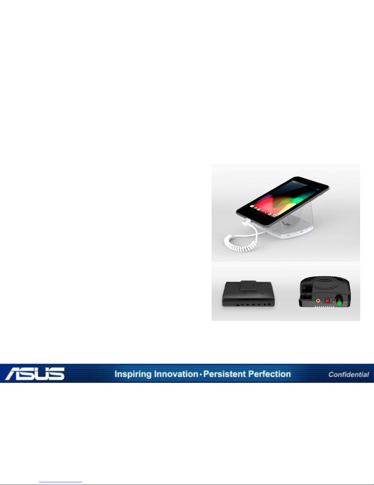
• This security system kit contains all the
materials needed to build an antitheft/anti-lost system for a product
displayed in an exhibition or retail store.
• The security system prevents a product
from being lost or stolen by triggering
off an alarm when it is separated from
the security sensor or when the security
cable is cut off.
• An administrator can turn off the alarm
conveniently with the remote control of
the security system kit.
• The security system can perform battery
charging and the security function at
the same time and can thus create a
stable and aesthetically pleasant
exhibition environment.
Page 3

1 PORT SECURITY ALARM
Page 4
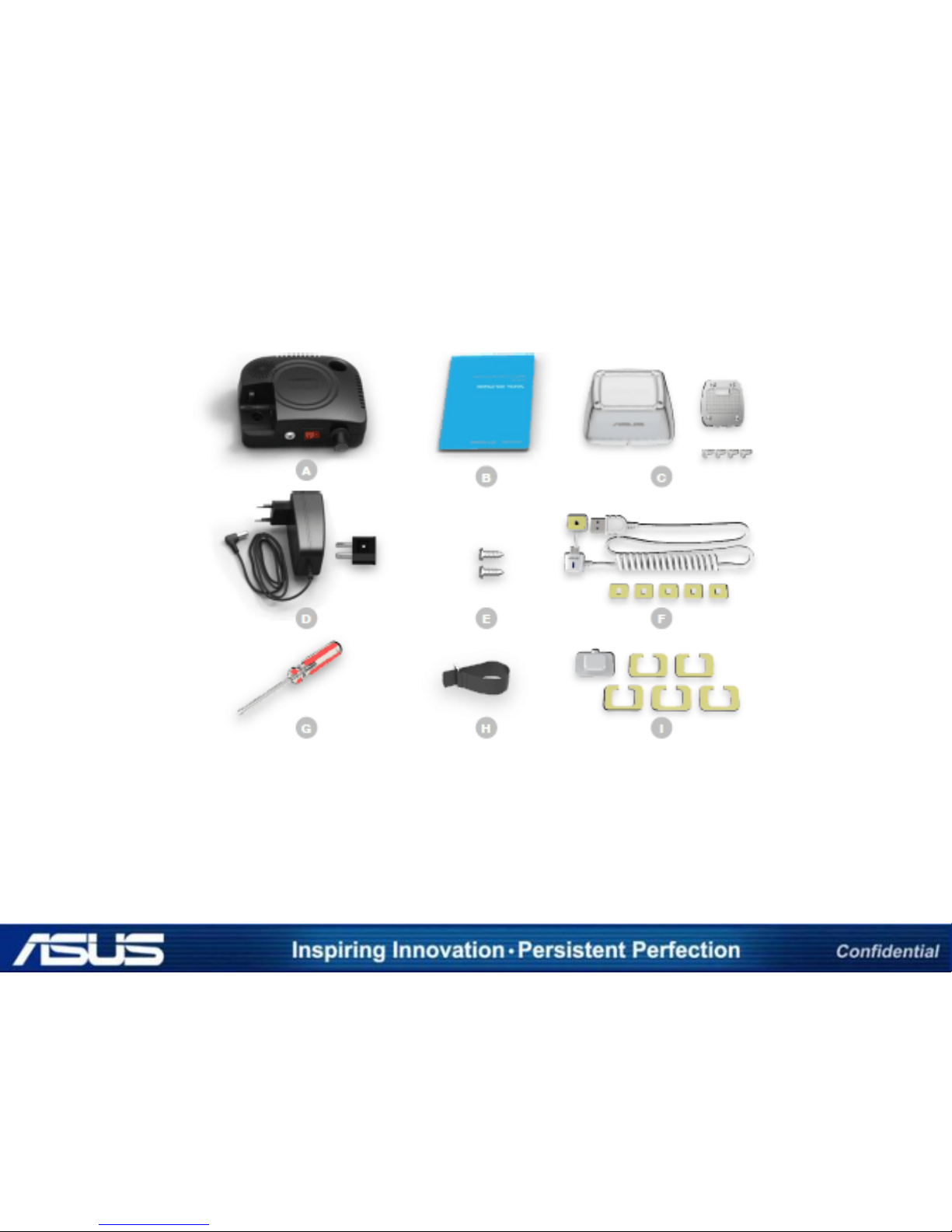
1 PORT - 1 SYSTEM TO 1 DEVICE
A Control box B Instruction manual C Tablet cradle assy. set
D AC adaptor set E 4.5 X 12mm screw(2EA) G Phillips-head screwdriver
H Velcro cable ties (1Set) I Sensor cap (5set)
Page 5
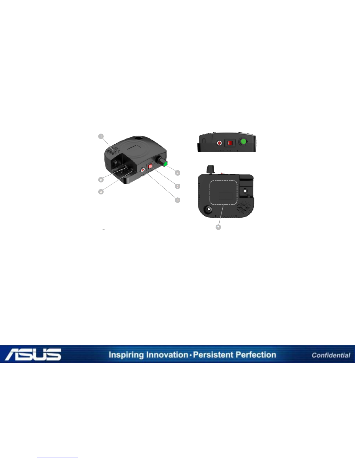
1 Speaker
Removes all the pairing settings between the control box
and the remote control.
2 USB Ports
Ports for plugging in the USB connectors of the charging &
security cable.
3 Power-in Port
Port for plugging in the power tip of the AC
4 Volume knob
Adjust the volume of alarm sound.
5 Power Switch
Turns DC power on or off in the control box.
DETAILS OF THE 1 PORT CONTROL BOX
6 LED Lamp
When the power switch is on, the red light turns on and DC
power is supplied.
7 Area for Double-sided Tape
Area to which double-sided tape should be attached for
mounting the control box.
Page 6
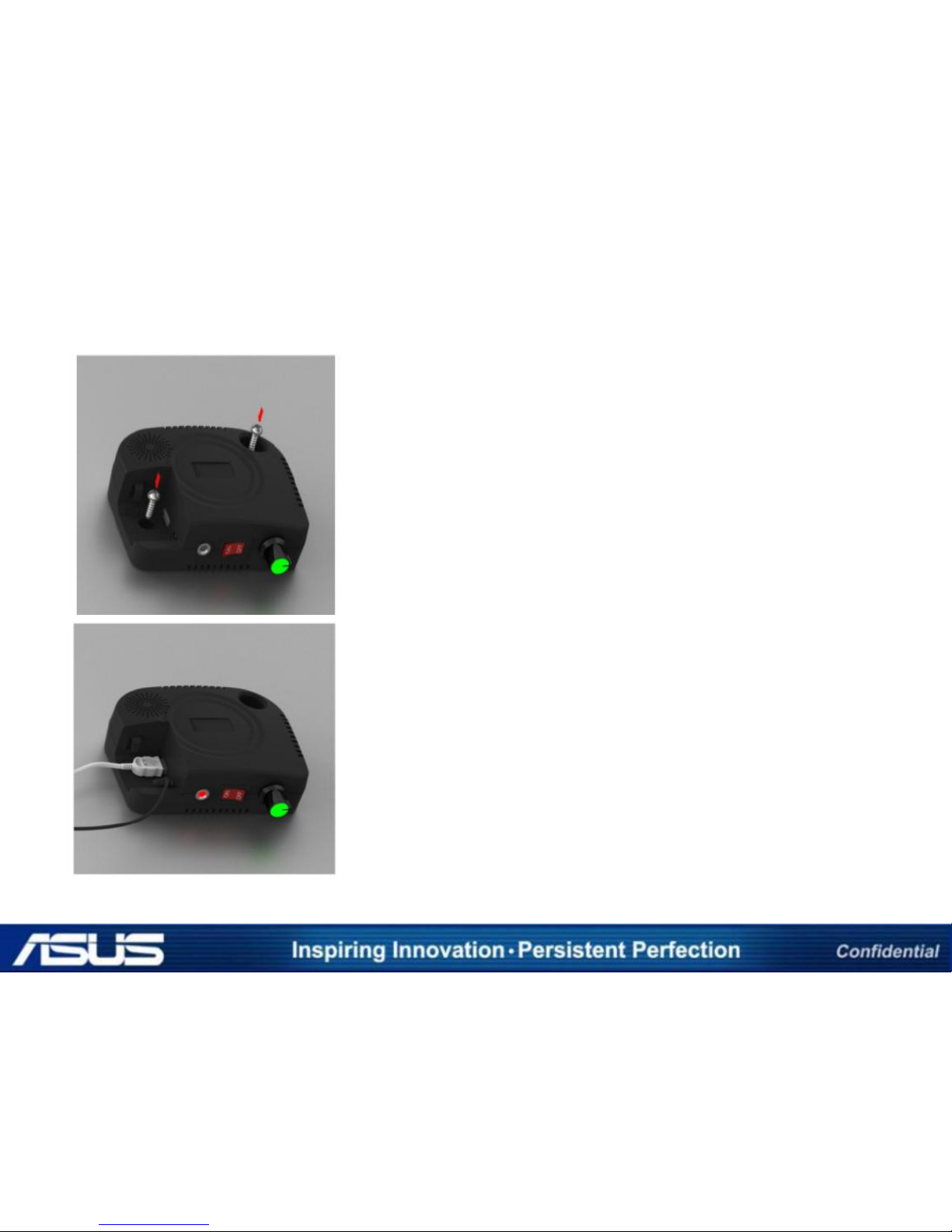
1 PORT DETAIL INSTALLATION PROCEDURE
STEP 1
For the final installation, determine where the
control box will be located. And then, Lock the
control box on the determined location with two
screws (4.5mmx12mm, You need to prepare a
Phillips screwdriver).
STEP 2
Plug the USB connectors of the Charging & security
cables and the power tip of the AC adaptor into
each corresponding port of the controller.
Turn the power on, and finish all the installation
job.
Page 7
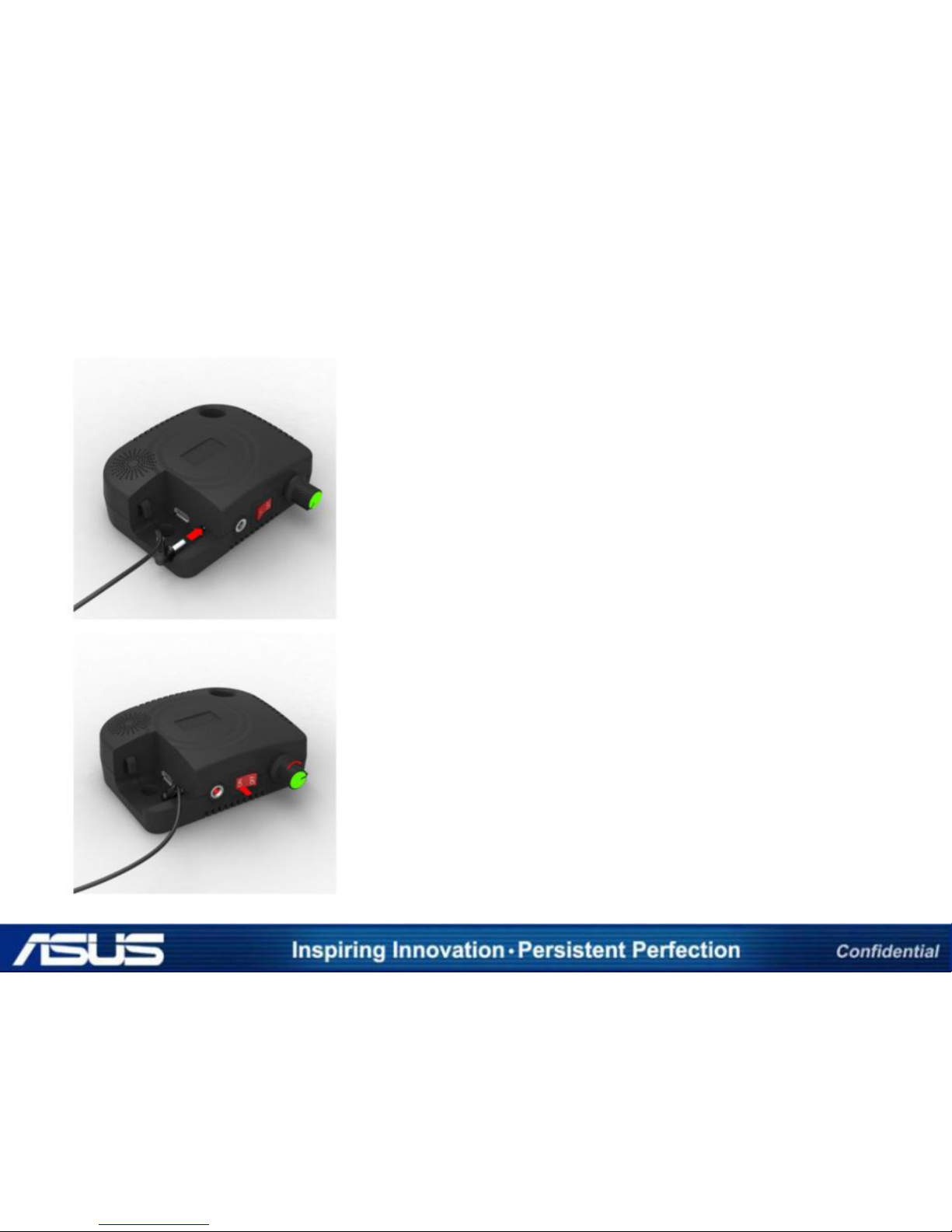
1 PORT DETAIL INSTALLATION PROCEDURE
STEP 3
Plug the power tip of AC adaptor to the power-in
port of the controller, and plug the AC adaptor to
an AC outlet. (AC 110~220V, Please use the
attached plug gender for 110V)
STEP 4
Turn the power switch on, and check the LED light
on.
If the volume dial is at the end in a counterclockwise direction, please turn the dial clockwise
for the volume not to be “Zero”
Page 8
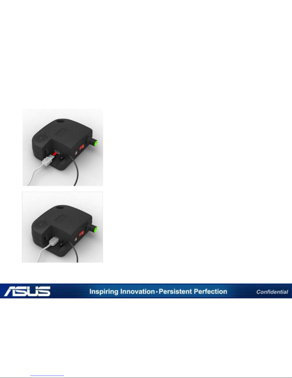
1 PORT DETAIL INSTALLATION PROCEDURE
STEP 5
Plug the USB connectors of the Charging & security
cables into the USB ports of the controller.
STEP 6
For testing of the connection between the security
sensor and tablet device, please unplug the USB
connector from the USB port. d finish all the
installation job.
Page 9
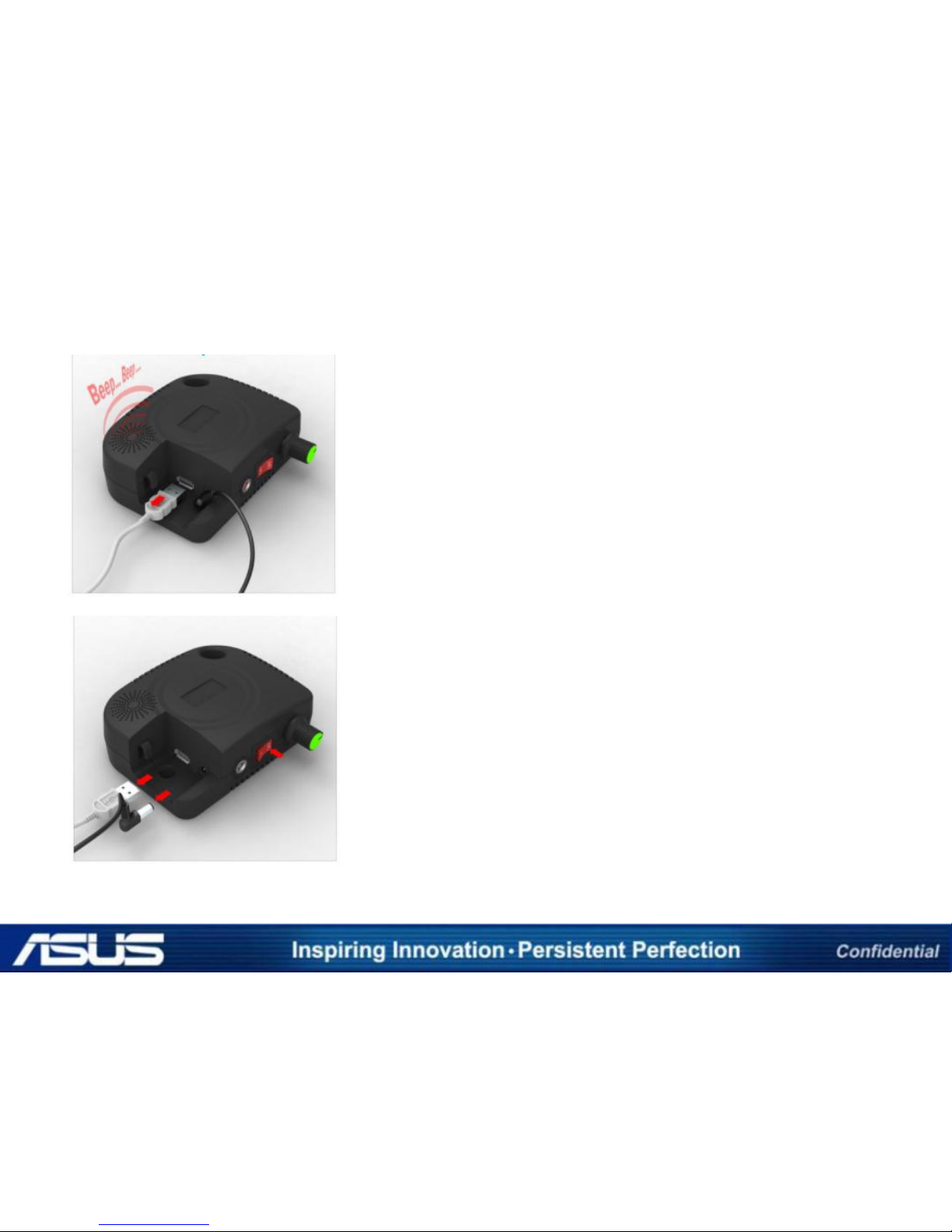
1 PORT DETAIL INSTALLATION PROCEDURE
STEP 9
If it rings the alarm sound, the connection is
successful. Otherwise, please check the connection,
and rework the chapter, ”CONNECTING THE
CAHRGING & SECURITY CABLE” of this installation
instructions.
STEP 10
If the test is successful, turn off the power and
unplug all the cables from the controller.
Page 10

5 PORT SECURITY ALARM
Page 11
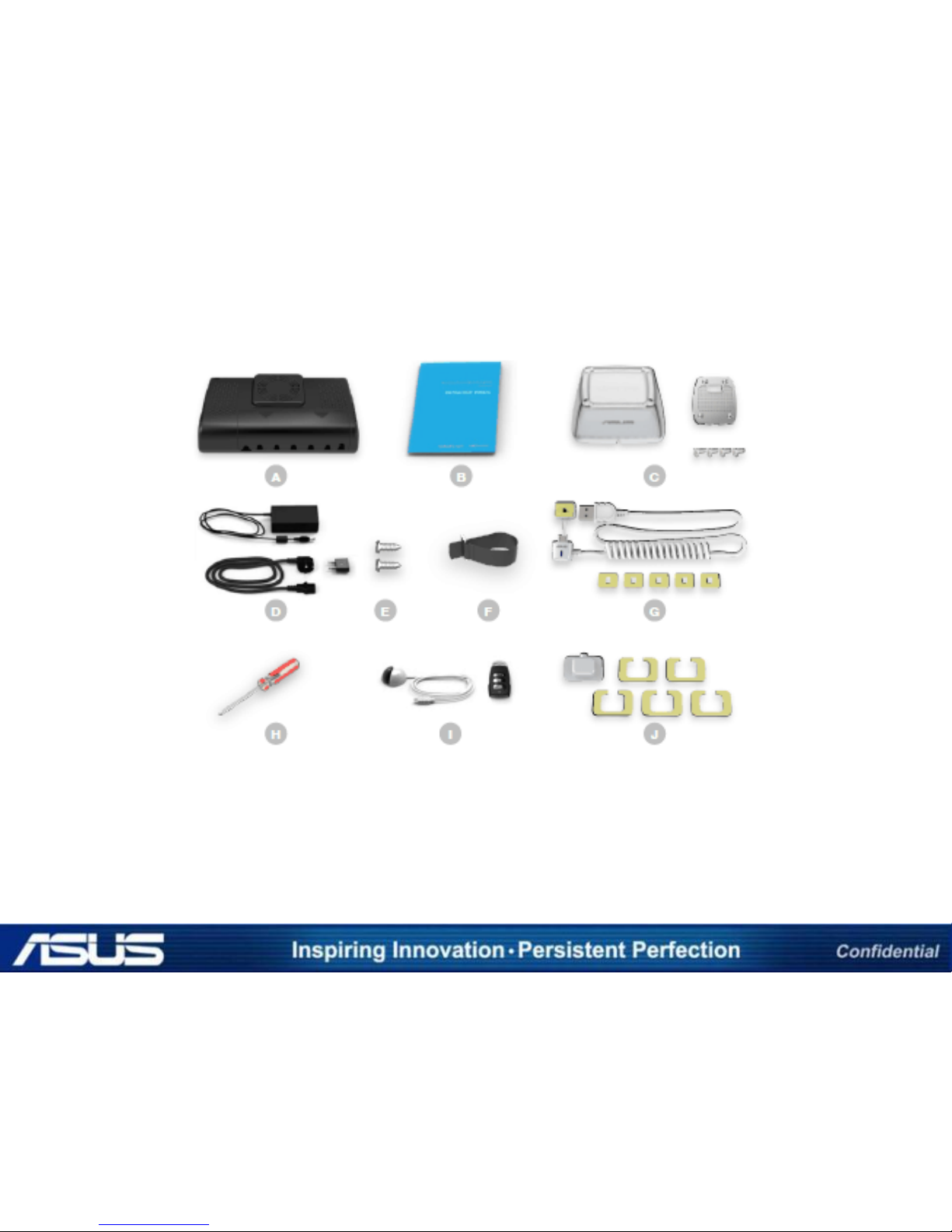
5 PORT - 1 SYSTEM TO 5 DEVICE
A Control box B Instruction manual C Tablet cradle assy. set (5Set)
D AC adaptor set E 4.5 X 12mm screw(2EA) F Velcro cable ties
G Charging & security cable (5set) H Phillips-head screwdriver
I Remote control set J Sensor cap (5set)
Page 12
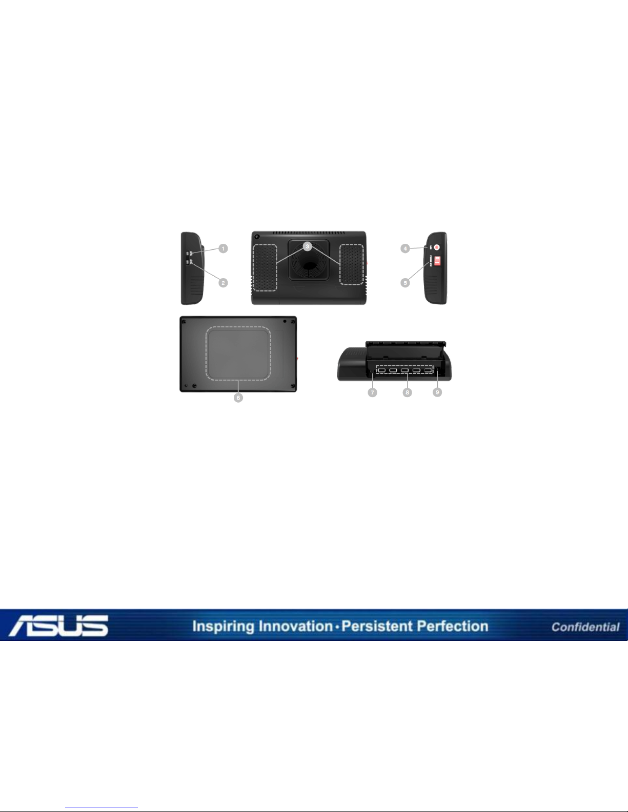
1 Pairing Reset Switch
Removes all the pairing settings between the control box
and the remote control
2 Pairing Setup Switch
Sets up the pairing between the control box and the remote
control Instruction manual
3 Speaker
Sounds the alarm when the security system is tampered
with.
4 LED Lamp
When the power switch is on, the red light turns on and DC
power is supplied.
5 Power Switch
Turns DC power on or off in the control box .
DETAILS OF THE 5 PORT CONTROL BOX
6 Area for Double-sided Tape
Area to which double-sided tape should be attached for
mounting the control box and the remote control.
7 Mini USB Port
Port for plugging in the mini USB connector of the IR sensor.
8 USB Ports
Ports for plugging in the USB connectors of the charging &
security cable.
9 Power-in Port
Port for plugging in the power tip of the AC Adaptor .
Page 13
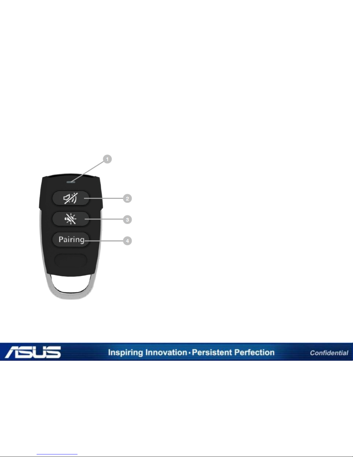
DETAILS OF THE REMOTE CONTROL – 5 PORT
1 LED indicator
The LED light blinks when the pairing setup is in progress,
and goes off when the pairing setup finishes.
2 Alarm off button
Turns off the alarm sound of the control box.
3 LED off button
Turns off the LED light of the security sensor of the charging
& security cable.
4 Pairing button
Sets up the pairing between the remote control and the
control box.
Page 14
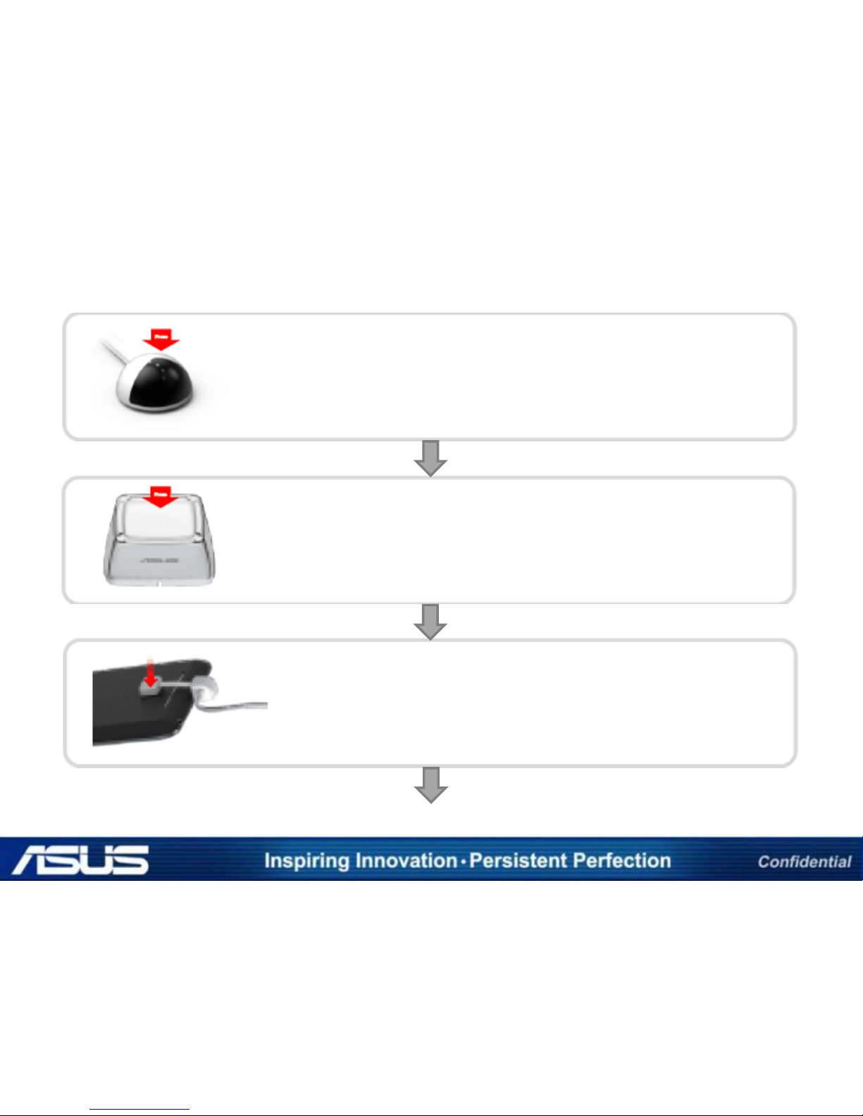
5 PORT - OVERVIEW OF INSTALLATION PROCEDURE
STEP 1
Mounting the IR sensor
STEP 2
Assembling & mounting the cradle
STEP 3
Connecting the charging & security cable
Page 15
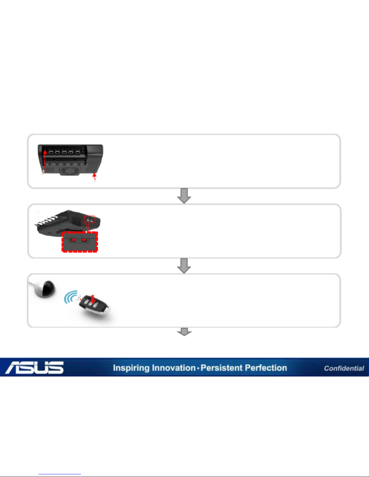
5 PORT - OVERVIEW OF INSTALLATION PROCEDURE
STEP 4
Installing the control box
STEP 5
Setting up the pairing with the remote control
STEP 6
Testing the pairing and sensor connection
COMPLETE
Page 16
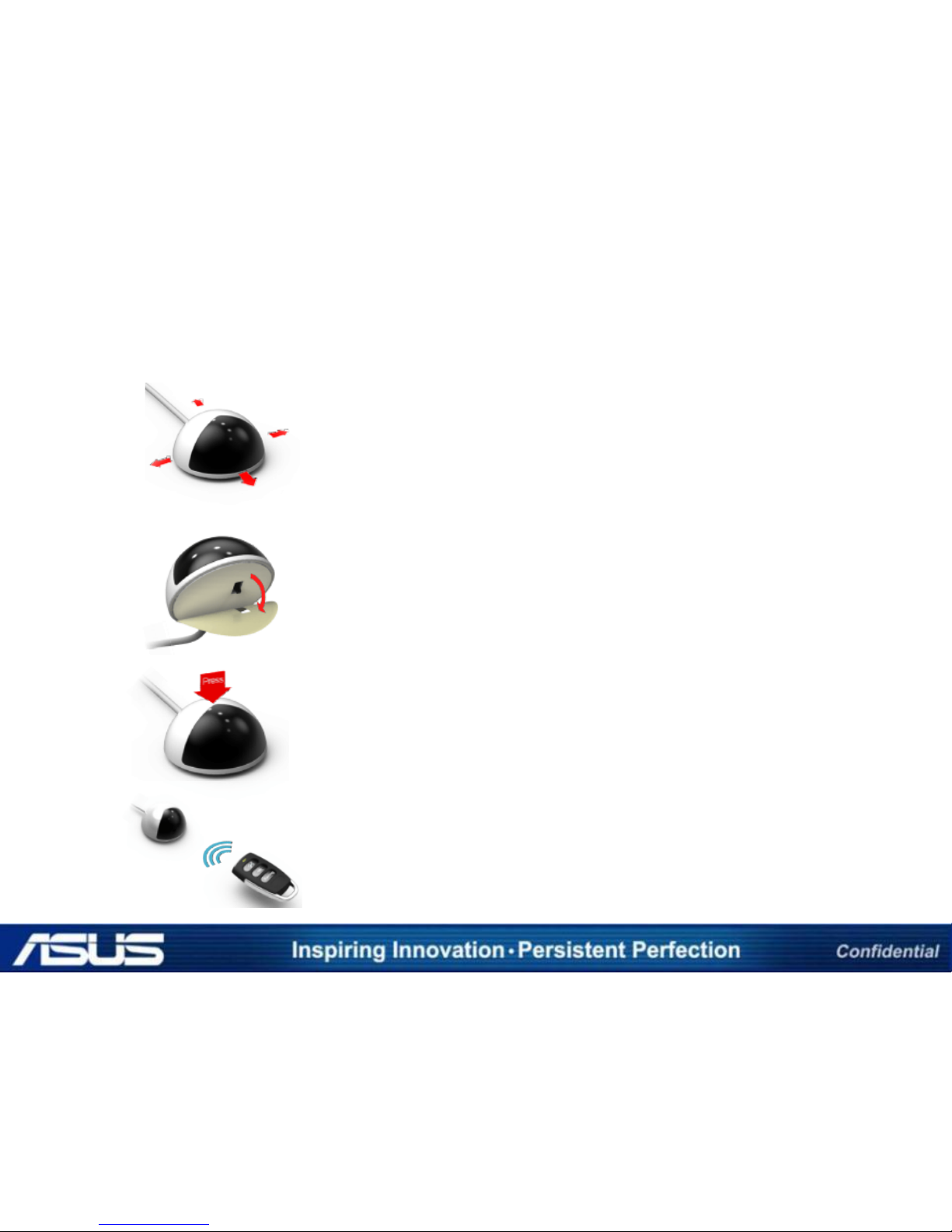
5 PORT DETAIL INSTALLATION PROCEDURE
STEP 1 - MOUNTING THE IR SENSOR
Peel off the protective film of the adhesive tape
underneath the sensor.
Determine where the IR sensor will be mounted on
the table, and clean the determined surface
thoroughly with a glass cleaner and a clean towel.
Remove all obstacles or hindrances to the IR
sensor so that it can receive the signal from the
remote control.
Press the sensor firmly on the determined surface
on the table.
Page 17
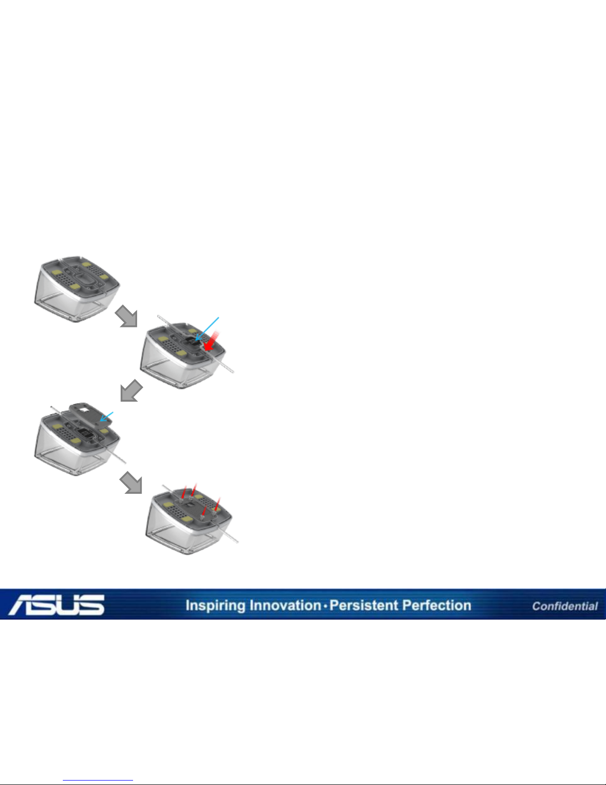
5 PORT DETAIL INSTALLATION PROCEDURE
STEP 2 - ASSEMBLING THE CRADLE
In order to make the assembling works more easier,
place the bottom of cradle facing up wards.
Match the position guide label on the middle of
the cradle, and push the charging & security cable
along the furrow.
After finish all the installing processes described
above, close the bottom lid and fasten the screws.
Position guide label
Bottom lid
Page 18
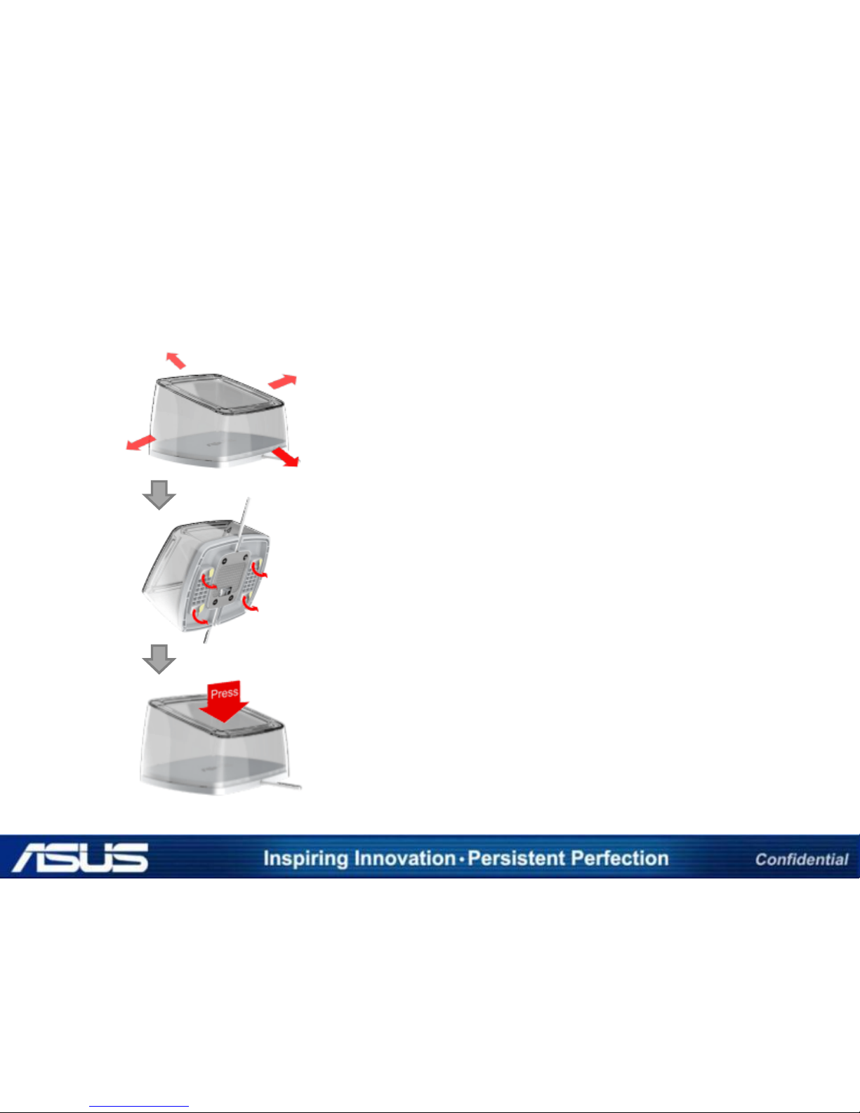
5 PORT DETAIL INSTALLATION PROCEDURE
STEP 2 - MOUNTING THE CRADLE
Determine where the cradle will be mounted on
the table, and clean the determined surface
thoroughly with a glass cleaner and a clean towel.
Peel off all the protective films of the adhesive
tapes underneath the cradle.
Press the cradle firmly on the determined surface
on the table.
Page 19
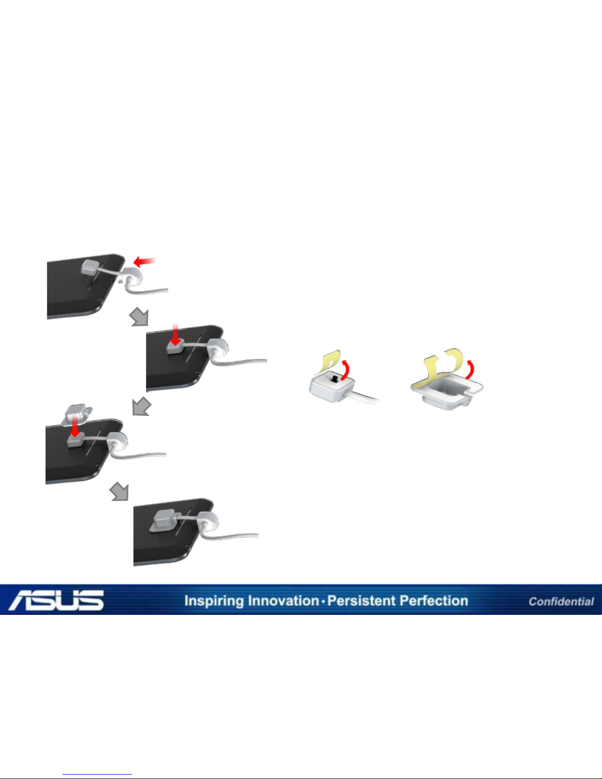
5 PORT DETAIL INSTALLATION PROCEDURE
STEP 3 - CONNECTING THE CHARGING & SECURITY CABLE
Plug the charging & security connector to the charging port
of tablet device.
※ The position of the charging port may vary depending
on the product.
Remove the dust or contaminants on sensor attachment
location and stick the security-sensor after peel off the
protecting film. (Refer the left image)
Stick the sensor cap on the security sensor after peel off
the protecting film. (Refer the left image)
※ The adhesion of the double-sided tape used for security
sensor attachment may vary depending on the material of
the adhesion side and the bend of the surface and the
adjacent temperature. Considering the nature of the
double-sided tape, the normal degree of adhesion can be
achieved at least 24 hours after adhesion.
Security sensor Sensor cap
After mounting the sensor, connect the charging & security
cable to the mobile phone.
Page 20
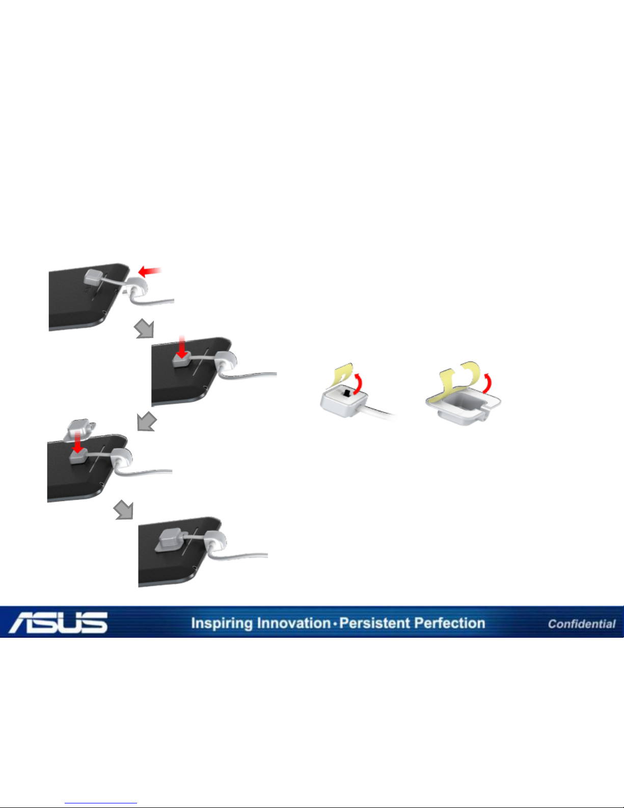
5 PORT DETAIL INSTALLATION PROCEDURE
STEP 3 - CONNECTING THE CHARGING & SECURITY CABLE
Plug the charging & security connector to the charging port
of tablet device.
※ The position of the charging port may vary depending
on the product.
Remove the dust or contaminants on sensor attachment
location and stick the security-sensor after peel off the
protecting film. (Refer the left image)
Stick the sensor cap on the security sensor after peel off
the protecting film. (Refer the left image)
※ The adhesion of the double-sided tape used for security
sensor attachment may vary depending on the material of
the adhesion side and the bend of the surface and the
adjacent temperature. Considering the nature of the
double-sided tape, the normal degree of adhesion can be
achieved at least 24 hours after adhesion.
Security sensor Sensor cap
After mounting the sensor, connect the charging & security
cable to the mobile phone.
Page 21
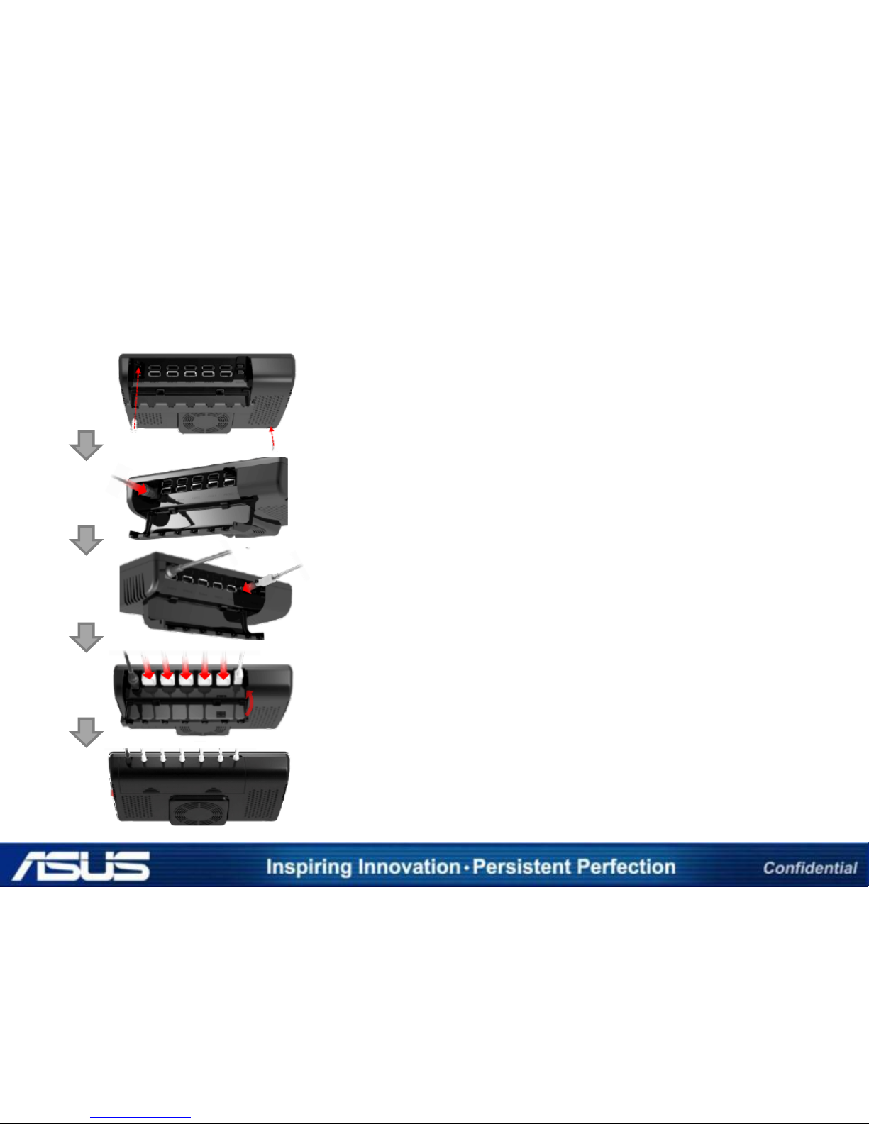
5 PORT DETAIL INSTALLATION PROCEDURE
STEP 4 - CONNECTING THE CHARGING & SECURITY CABLE
For the final installation, determine where the control box
will be located, then lock the control box onto the
determined location with two screws (4.5x12 mm; prepare
a “+” screwdriver beforehand).
Plug the power tip of the AC adaptor into the power-in
port of the control box, and plug the power cable into an
AC outlet (AC 110-220V; please use the enclosed plug
gender for 110V).
Plug the mini USB connector of the IR sensor into the mini
USB port of the control box.
Plug the USB connectors of the charging & security cables
into the USB ports of the control box (up to 5 cables can be
connected at once).
Close the lid. The installation is completed.
Page 22
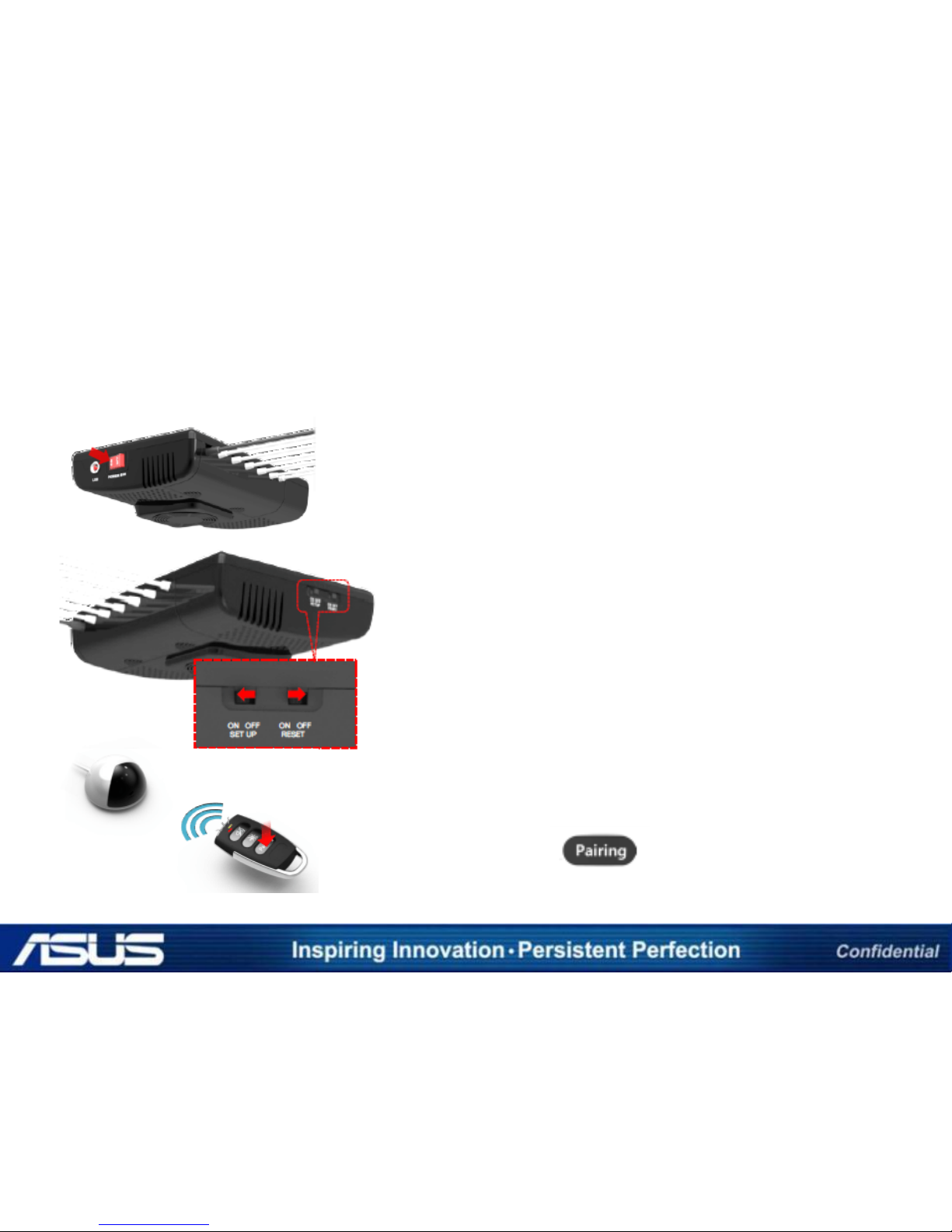
5 PORT DETAIL INSTALLATION PROCEDURE
STEP 5 - SETTING-UP THE PAIRING WITH REMOTE CONTROL
Turn on the power switch, and check if the LED light is on.
Turn on the pairing setup switch and turn off the pairing
reset switch.
Push the pairing button of the remote control. The LED
indicator of the remote control will blink. (After the
completion of the pairing, the LED indicator will go off.)
Pairing button icon:
Page 23

5 PORT DETAIL INSTALLATION PROCEDURE
STEP 5 - SETTING-UP THE PAIRING WITH REMOTE CONTROL
What is pairing?
“Pairing” is the configuration needed to make the control box and the
remote control transmit and receive the signal between each other.
-A control box can be paired with several numbers of remote controls.
-A remote control can be paired with several numbers of control boxes.
-The functions of the remote control can work only
Page 24
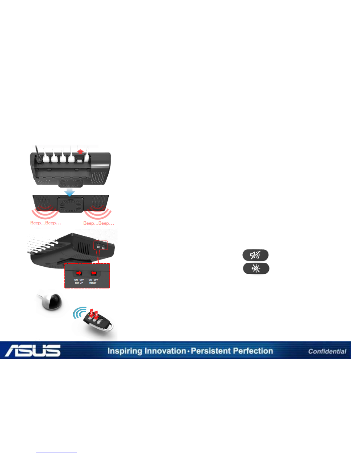
5 PORT DETAIL INSTALLATION PROCEDURE
STEP 6 - TESTING THE PAIRING AND SENSOR CONNECTION
For testing the pairing and sensor connection, please
unplug one of the USB connectors of the charging &
security cables from the USB port. If the alarm is triggered,
it means successful connection. Otherwise, please check
the connection and rework the chapter “Step 3.
Connecting the charging & security cable” of this
installation instruction manual .
Push the alarm off button (①) of the remote control to
turn off the alarm, and push the LED off button (②) to stop
the blinking of the LED light of the charging & security
cables’ security sensors.
Alarm off button icon:
LED off button icon:
To remove the current pairing setting, turn on the pairing
reset switch, and turn off the pairing setup switch. After
turning on the pairing reset switch, the remote control will
not work. To make the remote control work again, execute
the pairing process on “Step 5. Setting-up the pairing with
remote control” page of this installation instruction manual.
Page 25

5 PORT DETAIL INSTALLATION PROCEDURE
STEP 6 - TESTING THE PAIRING AND SENSOR CONNECTION
Cable short-circuit detection
When the short circuit is occurred by deterioration of cable, the short
alarm sounds constantly. In this case, the led on the cable is off and the
charging stops at the same time.
Counter measure
-Turn off the power switch on the control box and check the cable, in
case of cable is defective, replace the faulty cable with new one.
Page 26

The End
 Loading...