

Page 1

SABERTOOTH
990FX R2.0
Motherboard
Page 2

E8042
Revised Edition V2
January 2013
Copyright © 2013 ASUSTeK COMPUTER INC. All Rights Reserved.
No part of this manual, including the products and software described in it, may be reproduced,
transmitted, transcribed, stored in a retrieval system, or translated into any language in any form or by any
means, except documentation kept by the purchaser for backup purposes, without the express written
permission of ASUSTeK COMPUTER INC. (“ASUS”).
Product warranty or service will not be extended if: (1) the product is repaired, modied or altered, unless
such repair, modication of alteration is authorized in writing by ASUS; or (2) the serial number of the
product is defaced or missing.
ASUS PROVIDES THIS MANUAL “AS IS” WITHOUT WARRANTY OF ANY KIND, EITHER EXPRESS
OR IMPLIED, INCLUDING BUT NOT LIMITED TO THE IMPLIED WARRANTIES OR CONDITIONS OF
MERCHANTABILITY OR FITNESS FOR A PARTICULAR PURPOSE. IN NO EVENT SHALL ASUS, ITS
DIRECTORS, OFFICERS, EMPLOYEES OR AGENTS BE LIABLE FOR ANY INDIRECT, SPECIAL,
INCIDENTAL, OR CONSEQUENTIAL DAMAGES (INCLUDING DAMAGES FOR LOSS OF PROFITS,
LOSS OF BUSINESS, LOSS OF USE OR DATA, INTERRUPTION OF BUSINESS AND THE LIKE),
EVEN IF ASUS HAS BEEN ADVISED OF THE POSSIBILITY OF SUCH DAMAGES ARISING FROM ANY
DEFECT OR ERROR IN THIS MANUAL OR PRODUCT.
SPECIFICATIONS AND INFORMATION CONTAINED IN THIS MANUAL ARE FURNISHED FOR
INFORMATIONAL USE ONLY, AND ARE SUBJECT TO CHANGE AT ANY TIME WITHOUT NOTICE,
AND SHOULD NOT BE CONSTRUED AS A COMMITMENT BY ASUS. ASUS ASSUMES NO
RESPONSIBILITY OR LIABILITY FOR ANY ERRORS OR INACCURACIES THAT MAY APPEAR IN THIS
MANUAL, INCLUDING THE PRODUCTS AND SOFTWARE DESCRIBED IN IT.
Products and corporate names appearing in this manual may or may not be registered trademarks or
copyrights of their respective companies, and are used only for identication or explanation and to the
owners’ benet, without intent to infringe.
Offer to Provide Source Code of Certain Software
This product contains copyrighted software that is licensed under the General Public License (“GPL”),
under the Lesser General Public License Version (“LGPL”) and/or other Free Open Source Software
Licenses. Such software in this product is distributed without any warranty to the extent permitted by the
applicable law. Copies of these licenses are included in this product.
Where the applicable license entitles you to the source code of such software and/or other additional data,
you may obtain it for a period of three years after our last shipment of the product, either
(1) for free by downloading it from http://support.asus.com/download
or
(2) for the cost of reproduction and shipment, which is dependent on the preferred carrier and the location
where you want to have it shipped to, by sending a request to:
ASUSTeK Computer Inc.
Legal Compliance Dept.
15 Li Te Rd.,
Beitou, Taipei 112
Taiwan
In your request please provide the name, model number and version, as stated in the About Box of the
product for which you wish to obtain the corresponding source code and your contact details so that we
can coordinate the terms and cost of shipment with you.
The source code will be distributed WITHOUT ANY WARRANTY and licensed under the same license as
the corresponding binary/object code.
This offer is valid to anyone in receipt of this information.
ASUSTeK is eager to duly provide complete source code as required under various Free Open Source
Software licenses. If however you encounter any problems in obtaining the full corresponding source
code we would be much obliged if you give us a notication to the email address gpl@asus.com, stating
the product and describing the problem (please DO NOT send large attachments such as source code
archives, etc. to this email address).
ii
Page 3

Contents
Safety information ..................................................................................................... vii
About this guide ....................................................................................................... viii
SABERTOOTH 990FX R2.0 specications summary ............................................... x
Package contents ..................................................................................................... xiii
Installation tools and components ......................................................................... xiv
Chapter 1: Product introduction
1.1 Special features..........................................................................................1-1
1.1.1 Product highlights........................................................................1-1
1.1.2 “Ultimate COOL!” Thermal Solution ............................................ 1-2
1.1.3 “TUF ENGINE!” Power Design....................................................1-2
1.1.4 “Safe & Stable!” Guardian Angel ................................................. 1-3
1.1.5 ASUS EZ DIY ..............................................................................1-3
1.1.6 Other special features ................................................................. 1-4
1.2 Motherboard overview ............................................................................... 1-5
1.2.1 Before you proceed .....................................................................1-5
1.2.2 Motherboard layout ..................................................................... 1-6
1.2.3 Central Processing Unit (CPU) ...................................................1-8
1.2.4 System memory .......................................................................... 1-9
1.2.5 Expansion slots ......................................................................... 1-22
1.2.6 Onboard buttons .......................................................................1-24
1.2.7 Jumpers ....................................................................................1-26
1.2.8 Onboard LEDs ..........................................................................1-27
1.2.9 Internal connectors....................................................................1-28
Chapter 2: Basic Installation
2.1 Building your PC system...........................................................................2-1
2.1.1 Motherboard installation ..............................................................2-1
2.1.2 CPU installation...........................................................................2-4
2.1.3 CPU heatsink and fan assembly installation ............................... 2-5
2.1.4 DIMM installation.........................................................................2-7
2.1.5 ATX Power connection ................................................................ 2-8
2.1.6 SATA device connection ..............................................................2-9
2.1.7 Front I/O Connector ..................................................................2-10
2.1.8 Expansion Card installation....................................................... 2-11
2.2 BIOS update utility ................................................................................... 2-12
2.3 Motherboard rear and audio connections .............................................2-13
iii
Page 4

2.3.1 Rear I/O connection .................................................................. 2-13
2.3.2 Audio I/O connections ............................................................... 2-15
2.4 Starting up for the rst time .................................................................... 2-17
2.5 Turning off the computer ......................................................................... 2-18
Chapter 3: BIOS setup
3.1 Knowing BIOS ............................................................................................3-1
3.2 BIOS setup program ..................................................................................3-2
3.2.1 EZ Mode......................................................................................3-3
3.2.2 Advanced Mode .......................................................................... 3-4
3.3 Main menu ..................................................................................................3-6
3.4 Ai Tweaker menu ........................................................................................ 3-8
3.5 Advanced menu .......................................................................................3-17
3.5.1 CPU Conguration .................................................................... 3-18
3.5.2 North Bridge Conguration........................................................3-19
3.5.3 South Bridge Conguration ....................................................... 3-20
3.5.4 SATA Conguration ................................................................... 3-21
3.5.5 USB Conguration ....................................................................3-22
3.5.6 CPU Core On/Off Function .......................................................3-23
3.5.7 Onboard Devices Conguration ................................................ 3-24
3.5.8 APM ..........................................................................................3-26
3.5.9 Network Stack ........................................................................... 3-27
3.6 Monitor menu ...........................................................................................3-28
3.7 Boot menu ................................................................................................3-31
3.8 Tools menu ............................................................................................... 3-33
3.8.1 ASUS EZ Flash 2 Utility ............................................................ 3-33
3.8.2 ASUS SPD Information ............................................................. 3-34
3.8.3 ASUS O.C. Prole ..................................................................... 3-35
3.9 Exit menu .................................................................................................. 3-36
3.10 Updating BIOS .......................................................................................... 3-37
3.10.1 ASUS Update ............................................................................ 3-37
3.10.2 ASUS EZ Flash 2 ...................................................................... 3-40
3.10.3 ASUS BIOS Updater ................................................................. 3-41
Chapter 4: Software support
4.1 Installing an operating system .................................................................4-1
4.2 Support DVD information .......................................................................... 4-1
4.2.1 Running the support DVD ........................................................... 4-1
4.2.2 Obtaining the software manuals..................................................4-2
iv
Page 5

4.3 Software information .................................................................................4-3
4.3.1 AI Suite II.....................................................................................4-3
4.3.2 ASUS TUF Thermal Radar .........................................................4-4
4.3.3 Remote GO! ................................................................................ 4-8
4.3.4 TurboV EVO .............................................................................. 4-19
4.3.5 DIGI+ Power Control .................................................................4-22
4.3.6 Sensor Recorder ....................................................................... 4-25
4.3.7 Ai Charger+ ...............................................................................4-27
4.3.8 USB 3.0 Boost...........................................................................4-28
4.3.9 USB BIOS Flashback Wizard....................................................4-29
4.3.10 Network iControl........................................................................4-31
4.3.11 ASUS Update ............................................................................ 4-36
4.3.12 MyLogo2 ...................................................................................4-37
4.3.13 Audio congurations..................................................................4-38
Chapter 5: RAID support
5.1 RAID congurations ..................................................................................5-1
5.1.1 RAID denitions ..........................................................................5-1
5.1.2 Installing Serial ATA hard disks ...................................................5-2
5.1.3 Setting the RAID item in BIOS .................................................... 5-2
5.1.4 AMD® Option ROM Utility ............................................................ 5-3
5.2 Creating a RAID driver disk.......................................................................5-7
5.2.1 Creating a RAID driver disk without entering the OS .................. 5-7
5.2.2 Creating a RAID driver disk in Windows® .................................... 5-7
5.2.3 Installing the RAID driver during Windows® OS installation ........ 5-8
5.2.4 Using a USB oppy disk drive ..................................................... 5-9
Chapter 6: Multiple GPU support
6.1 AMD® CrossFireX™ technology ...............................................................6-1
6.1.1 Requirements .............................................................................. 6-1
6.1.2 Before you begin ......................................................................... 6-1
6.1.3 Installing two CrossFireX™ graphics cards ................................6-2
6.1.4 Installing the device drivers ......................................................... 6-4
6.1.5 Enabling the AMD® CrossFireX™ technology ............................. 6-4
6.2 NVIDIA® SLI™ technology ......................................................................... 6-6
6.2.1 Requirements .............................................................................. 6-6
6.2.2 Installing two SLI-ready graphics cards ......................................6-6
v
Page 6

6.2.3 Installing the device drivers ......................................................... 6-7
6.2.4 Enabling the NVIDIA® SLI™ technology ..................................... 6-8
Appendices
Notices .................................................................................................................... A-1
ASUS contact information ...................................................................................... A-4
vi
Page 7

Safety information
Electrical safety
•
To prevent electrical shock hazard, disconnect the power cable from the electrical outlet
before relocating the system.
When adding or removing devices to or from the system, ensure that the power cables
•
for the devices are unplugged before the signal cables are connected. If possible,
disconnect all power cables from the existing system before you add a device.
Before connecting or removing signal cables from the motherboard, ensure that all
•
power cables are unplugged.
Seek professional assistance before using an adapter or extension cord. These devices
•
could interrupt the grounding circuit.
Ensure that your power supply is set to the correct voltage in your area. If you are not
•
sure about the voltage of the electrical outlet you are using, contact your local power
company.
If the power supply is broken, do not try to x it by yourself. Contact a qualied service
•
technician or your retailer.
Operation safety
Before installing the motherboard and adding devices on it, carefully read all the manuals
•
that came with the package.
Before using the product, ensure all cables are correctly connected and the power
•
cables are not damaged. If you detect any damage, contact your dealer immediately.
To avoid short circuits, keep paper clips, screws, and staples away from connectors,
•
slots, sockets and circuitry.
Avoid dust, humidity, and temperature extremes. Do not place the product in any area
•
where it may become wet.
Place the product on a stable surface.
•
If you encounter technical problems with the product, contact a qualied service
•
technician or your retailer.
vii
Page 8

About this guide
This user guide contains the information you need when installing and conguring the
motherboard.
How this guide is organized
This guide contains the following parts:
• Chapter 1: Product introduction
This chapter describes the features of the motherboard and the new technology it
supports. It includes description of the switches, jumpers, and connectors on the
motherboard.
• Chapter 2: Basic Installation
This chapter lists the hardware setup procedures that you have to perform when
installing system components.
• Chapter 3: BIOS setup
This chapter tells how to change system settings through the BIOS Setup menus.
Detailed descriptions of the BIOS parameters are also provided.
• Chapter 4: Software support
This chapter describes the contents of the support DVD that comes with the
motherboard package and the software.
• Chapter 5: RAID support
This chapter describes the RAID congurations.
• Chapter 6: Multiple GPU technology support
This chapter describes how to install and congure multiple AMD® CrossFireX™ and
NVIDIA® SLI™ graphics cards.
Where to nd more information
Refer to the following sources for additional information and for product and software
updates.
1. ASUS websites
The ASUS website provides updated information on ASUS hardware and software
products. Refer to the ASUS contact information.
2. Optional documentation
Your product package may include optional documentation, such as warranty yers,
that may have been added by your dealer. These documents are not part of the
standard package.
viii
Page 9

Conventions used in this guide
To ensure that you perform certain tasks properly, take note of the following symbols used
throughout this manual.
DANGER/WARNING: Information to prevent injury to yourself when trying to
complete a task.
CAUTION: Information to prevent damage to the components when trying to
complete a task
IMPORTANT: Instructions that you MUST follow to complete a task. .
NOTE: Tips and additional information to help you complete a task.
Typography
Bold text Indicates a menu or an item to select.
Italics
<Key> Keys enclosed in the less-than and greater-than sign
<Key1> + <Key2> + <Key3> If you must press two or more keys simultaneously, the key
Used to emphasize a word or a phrase.
means that you must press the enclosed key.
Example: <Enter> means that you must press the Enter or
Return key.
names are linked with a plus sign (+).
ix
Page 10

SABERTOOTH 990FX R2.0 specications summary
CPU AMD® Socket AM3+ for AMD® FX series CPU up to 8-core
compatible with AMD® Socket AM3 for AMD® Phenom™ II /
Athlon II™ / Sempron™ 100 series processors
Supports AMD® 140W CPU
AMD® Cool ‘n’ Quiet Technology
Supports 32nm CPU
Chipset AMD® 990FX / SB950 Chipset
System Bus Up to 5.2 GT/s HyperTransport™ 3.0
Memory 4 x DIMM, max. 32GB, DDR3 1866 / 1600 / 1333 / 1066 MHz, ECC,
non-ECC, un-buffered memory
Dual channel memory architecture
* Refer to www.asus.com for Memory QVL (Qualied Vendors List) of
AM3+ / AM3 CPU for details.
** Due to OS limitation, when installing a total memory of 4GB capacity
or more, Windows® 32-bit operation system may only recognize
less than 3GB. Hence, a total installed memory of less than 3GB is
recommended.
*** Due to CPU specications, AMD 100 Series CPUs support up to DDR3
1066MHz. With ASUS design, this motherboard can support up to
DDR3 1333MHz.
Expansion slots 3 x PCI Express 2.0 x16 slots (Dual at x16/x16, triple at x16/x8/x8
mode)*
1 x PCI Express 2.0 x16 slot [black] (supports x4 mode)
1 x PCI Express 2.0 x1 slot
1 x PCI slot
* When running dual graphics cards, ensure to insert the card in the rst
and third PCI Express X16 slot to get the best performance.
Multi-GPU support Supports NVIDIA® QUAD-GPU SLI™ Technology
Supports AMD® QUAD-GPU CrossFireX™ Technology
LAN Realtek® 8111F Gigabit LAN controller
Storage
AMD® SB950 Chipset
- 6 x SATA 6.0 Gb/s ports with RAID 0, 1, 5 and 10 support
ASMedia® SATA 6Gb/s controllers
- 2 x SATA 6Gb/s ports
- 2 x eSATA 6Gb/s ports [red]
Audio
Realtek® ALC892 8-channel high denition audio
CODEC
- Absolute Pitch 192khz/24bit True BD Lossless Sound
- BD audio layer content protection
- Supports jack-detection, multi-streaming and front panel jackretasking
- Optical S/PDIF out ports at back I/O
- ASUS noise lter
(continued on the next page)
x
Page 11

SABERTOOTH 990FX R2.0 specications summary
USB
3 x ASMedia® USB 3.0 controllers
- 2 x USB 3.0 ports at mid-board for front panel support
- 4 x USB 3.0 ports at back panel [blue]
AMD® SB950 Chipset
- 12 x USB 2.0 ports (4 ports at mid-board, 8 ports at back
panel)
Exclusive TUF features
“Ultimate COOL” Thermal Solution
- TUF CeraM!X heatsink coating technology
- TUF Thermal radar
TUF ENGINE! Digital Power Design
- 8+2 Digital phase power design
- TUF Components (alloy choke, Cap & MOSFET certied by
military standard)
- ASUS DIGI+ Power Control utility
- Efcient Switching Power (E.S.P.) design
Safe & Stable! Guardian Angel
- ESD Guards
- MemOK!
- Anti Surge
Other special features Front panel USB 3.0 support
Remote GO!
USB 3.0 Boost
Network iControl
ASUS UEFI BIOS EZ Mode
USB BIOS Flashback
AI Suite II
ASUS Q-Connector
ASUS Q-Shield
ASUS Q-LED (CPU, DRAM, VGA, Boot Device LED)
ASUS Q-Slot
ASUS Q-DIMM
ASUS O.C. Prole
Ai Charger+
ASUS EZ Flash 2
ASUS MyLogo2
Multi-language BIOS
(continued on the next page)
xi
Page 12

SABERTOOTH 990FX R2.0 specications summary
Back Panel I/O ports 1 x PS/2 keyboard/mouse combo port
1 x Optical S/PDIF Output port
2 x eSATA 6Gb/s ports [red]
1 x USB BIOS Flashback button
1 x LAN (RJ-45) port
4 x USB 3.0/2.0 ports [blue]
8 x USB 2.0/1.1 ports
6 x Audio jacks for 8-channel Audio I/O ports
Internal I/O connectors 1 x USB 3.0/2.0 connector (supports additional 2 19-pin USB
BIOS features 64 Mb Flash ROM, UEFI BIOS, PnP, SLP2.1, DMI 2.0, WfM 2.0,
Manageability WfM 2.0, DMI 2.0, WOL by PME, WOR by PME, PXE
Support DVD contents Drivers
Form factor ATX form factor: 12 in. x 9.6 in. (30.5 cm x 24.4 cm)
3.0/2.0 ports [moss green])
2 x USB 2.0/1.1 connectors (support additional 4 USB 2.0/1.1 ports)
6 x SATA 6Gb/s connectors [brown]
2 x SATA 6Gb/s connectors [gray]
1 x CPU Fan connector (4-pin)
1 x CPU Optional fan connector (4-pin)
4 x Chassis fan connectors (4-pin)
1 x TPM header
1 x COM connector
1 x S/PDIF Out header
1 x DirectKey button
1 x DRCT header
1 x MemOK! button
1 x Clear CMOS jumper
24-pin EATX power connector
8-pin EATX 12V power connector
Front panel audio connector
System panel (Q-Connector)
SM BIOS 2.7, ACPI 2.0a, Multi-language BIOS, ASUS EZ Flash 2,
F12 PrintScreen function, F3 Shortcut function, and ASUS DRAM
SPD (Serial Presence Detect) memory information
ASUS Utilities
ASUS Update
Anti-virus software (OEM version)
Specications are subject to change without notice.
xii
Page 13
Package contents
User Manual
Five-year warranty
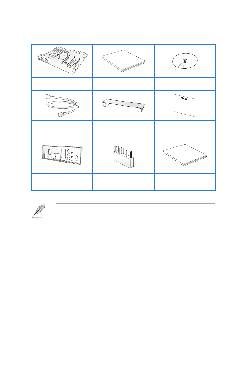
Check your motherboard package for the following items.
ASUS SABERTOOTH 990FX R2.0
motherboard
4 x Serial ATA 6.0 Gb/s cables 1 x ASUS SLI™ bridge connector 1 x TUF Certication card
1 x ASUS Q-Shield 1 x 2-in-1 ASUS Q-Connector kit 1 x TUF Five-year warranty manual
• If any of the above items is damaged or missing, contact your retailer.
• The illustrated items above are for reference only. Actual product specications may
vary with different models.
User manual Support DVD
xiii
Page 14
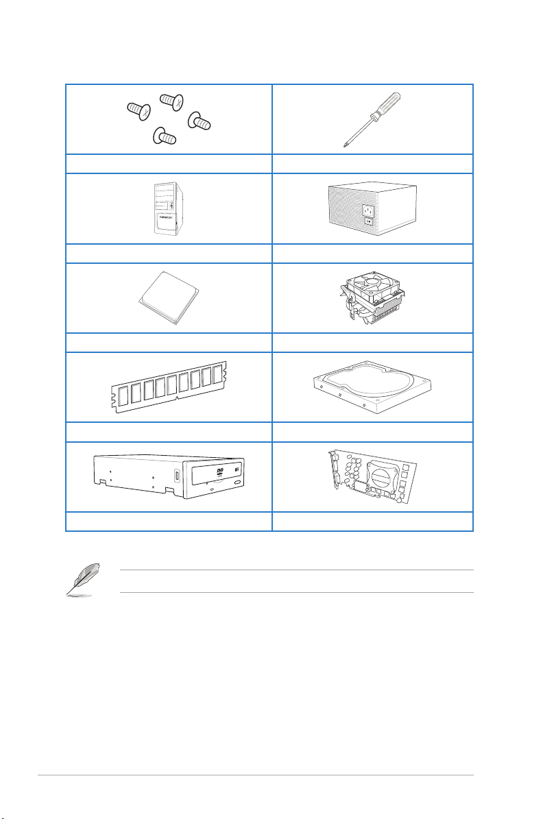
Installation tools and components
1 bag of screws Philips (cross) screwdriver
PC chassis Power supply unit
AMD AM3+ CPU AMD AM3+ compatible CPU Fan
xiv
DDR3 DIMM
SATA optical disc drive (optional) Graphics card (optional)
SATA hard disk drive
The tools and components in the table above are not included in the motherboard package.
Page 15

Product introduction
1
1.1 Special features
1.1.1 Product highlights
The Ultimate Force
The TUF series delivers a tough image with its unique design, and high-quality and militarystandard components. The TUF series pursues pre-eminent stability, all-around compatibility,
and extreme durability.
FX™/Phenom™ II/Athlon™ II/ Sempron™ 100 Series Processors (AM3+ / AM3
CPU)
This motherboard supports AMD® Socket AM3+ multi-core processors with up to 8-core
native CPU cores, and AMD® CPUs in the new 32nm manufacturing process. It provides
better overclocking capabilities with less power consumption. It features AMD Turbo CORE
Technology 2.0 to accelerate data transfer rate up to 5200MT/s rate via HyperTransport™ 3.0
based system bus.
AMD® 990FX Chipset
AMD 990FX Chipset is designed to support up to 5.2GT/s HyperTransport™ 3.0 (HT 3.0)
interface speed and dual PCI Express™ 2.0 x16 graphics. It is optimized with AMD AM3+
and multi-core CPUs to provide excellent system performance and overclocking capabilities.
PCI Express® 2.0
This motherboard supports the latest PCIe 2.0 devices for double speed and bandwidth that
enhances system performance.
QUAD-GPU SLI and QUAD-GPU CrossFireX™ Support
This motherboard supports multi-GPU congurations of both SLI™ and CrossFireX. This
motherboard features the AMD® 990FX/SB950 platform, optimizing PCIe allocation in multiple
GPU setups.
Dual-Channel 1866 MHz Support
The motherboard supports the dual-channel DDR3 memory that features data transfer
rates of 1866 MHz to boost the system’s performance, and to meet the higher bandwidth
requirements of 3D graphics, multimedia, and Internet applications.
ASUS SABERTOOTH 990FX R2.0
Chapter 1
1-1
Page 16

Complete USB 3.0 Solution
This motherboard offers you the strategic USB 3.0 accessibility for both the front and rear
panels, allowing you to experience the convenience of the latest plug and play connectivity
solution at speed up to ten times faster than USB 2.0.
1.1.2 “Ultimate COOL!” Thermal Solution“Ultimate COOL!” Thermal Solution
TUF CeraM!X - Heatsink Coating Technology
This feature offers better cooling solution for an overall improvement in system stability. Its
innovative ceramics actively conducts heat away from the system, and replaces traditional
anti-oxidant for better heat dissipation.
TUF Thermal Radar
The TUF Thermal Radar monitors the temperature of the motherboard’s critical parts and
automatically adjusts fan speeds in real time to ensure that the system remains stable and
does not overheat. It consists of multiple sensors for various components, allowing you to
monitor each area, while increasing options for fan control housed inside the chassis. The
Thermal Radar calculates ideal fan speeds based on different parameters that you have
selected for each component, keeping your system cool and more stable.
1.1.3 “TUF ENGINE!” Power Design
DIGI+ Power Control
DIGI+ Power Control includes multiple digital voltage controllers, allowing ultra-precise
modulation and tuning of both CPU and DRAM. This innovative and industry-leading ASUS
technology provides accurate voltage tuning for better efciency, stability, and performance.
Efcient Switching Power (E.S.P.) Design
E.S.P., an ASUS exclusive feature, is designed for key components such as CPU, memory,
graphics cards, LAN, and USB 3.0 to help improve system efciency and reduce heat
generation.
TUF Components (Choke, Cap. & MOSFET; certied by military-standard)
This motherboard provides rugged performance even in the most challenging conditions
with its robust TUF chokes, solid capacitors, and MOSFETs, which are certied through a
Chapter 1
third-party, military-grade testing. TUF Chokes or Alloy Choke is made up of a compound
of various metals instead of the standard iron, which supports up to 40A rated current,
25% higher than the standard chokes. The TUF Chokes are packaged in a single piece,
eliminating the emission of vibration noise, delivering superb characteristics, and durability
under extreme conditions.
DO NOT uninstall the heatsink module by yourself. Doing so may bend the tubing and
affect the heat dissipation performance.
1-2
Chapter 1: Product introduction
Page 17

1.1.4 “Safe & Stable!” Guardian Angel
ESD Guards
ESD (Electrostatic Discharge) Guards provides protection against electrostatic discharges,
which can damage the motherboard’s components. The ASUS exclusive Anti-Static chip
and circuit design, and the I/O shield provide four times better protection and ensure the
motherboard’s lifespan.
MemOK!
MemOK!, the remarkable memory rescue tool, allows you to simply press a button to
patch memory issues, ensure memory boot compatibility, determine fail-safe settings, and
dramatically improve the system’s bootup.
1.1.5 ASUS EZ DIY
ASUS UEFI BIOS (EZ Mode)
ASUS UEFI BIOS, a UEFI compliant architecture, offers the rst mouse-controlled intuitive
graphical BIOS interface that goes beyond the traditional keyboard-only BIOS controls,
providing you with more exibility, convenience, and easy to navigate EFI BIOS than the
traditional BIOS versions. It offers you with dual selectable modes and native support for hard
drives larger than 2.2 TB.
ASUS UEFI BIOS includes the following new features:
• F12 BIOS snapshot hotkey
• F3 Shortcut for most accessed information
• ASUS DRAM SPD (Serial Presence Detect) information detecting faulty DIMMs, and
helping with difcult POST situations.
DirectKey
DirectKey allows you to conveniently go into the BIOS setup with the press of a button. With
this feature, you can enter the BIOS anytime without having to press the <Del> key during
POST. It also allows you to shut down or turn on your computer and directly enter the BIOS
during boot-up.
Remote GO!
Remote GO! links PCs, tablets, smartphones, and TVs wirelessly together through an
existing LAN cable and route setup. It provides a seamless environment for a futuristic
connected lifestyle with three useful functions:
DLNA Media Hub: Enjoy HD video, music and photos stored in your PC, streaming to
•
your DLNA devices via Wi-Fi. You can even use your tablet to control your PC to play
multimedia contents.
Remote Desktop: Operate and control your PC in real time from a smartphone or tablet
•
for complete comfort and convenience.
File Transfer: Send and share les between your PC and smart devices* with only a
•
right click on the mouse.
* iPad/iPhone can send les, but cannot receive le transfers from PC.
Chapter 1
ASUS SABERTOOTH 990FX R2.0
1-3
Page 18

USB BIOS Flashback
USB BIOS F lashback offers a hassle-free updating solution for your ultimate convenience.
Install a USB storage device containing the BIOS le, press the BIOS Flashback button for
about three seconds, and the UEFI BIOS is automatically updated even without entering
the existing BIOS or operating system. It also allows you to regularly check for UEFI BIOS
updates, and download the latest BIOS automatically.
USB 3.0 Boost
ASUS USB 3.0 Boost technology, which supports UASP (USB Attached SCSI Protocol),
automatically accelerates the data transfer speed of a USB 3.0 device up to 170% faster than
the standard USB 3.0 transfer speed.
Network iControl
Network iControl is an intuitive one-step network control center that makes it easier for you to
manage your bandwidth and allows you to set, monitor, and schedule the bandwidth priorities
for your network programs. It allows you to automatically connect to a PPPoE network for a
more convenient online experience.
ASUS EZ-Flash 2
ASUS EZ Flash 2 is a user-friendly utility that allows you to update the BIOS without using a
bootable oppy disk or an OS-based utility.
O.C. Prole
This motherboard features the ASUS O.C. Prole that allows you to store or load multiple
BIOS settings. The BIOS settings can be stored in the CMOS or a separate le, giving you
the freedom to share and distribute your favorite overclocking settings.
1.1.6 Other special features
8 Channel Audio Codec
The onboard 8-channel HD audio (High Denition Audio, previously codenamed Azalia)
CODEC enables high-quality Absolute Pitch 192kHz/24bit audio output, true BD lossless
sound, jack-sensing feature, retasking functions and multi-streaming technology.
S/PDIF-out on Back I/O port
This motherboard provides a convenient connectivity to external home theater audio systems
via optical S/PDIF-out (Sony-Philips Digital Interface) jacks. It allows the system to transfer
digital audio without converting to analog format and keeps the best signal quality.
ErP Ready
Chapter 1
The motherboard is European Union’s Energy-related Products (ErP) ready, and ErP requires
products to meet certain energy efciency requirement in regards to energy consumptions.
This is in line with ASUS vision of creating environment-friendly and energy-efcient products
through product design and innovation to reduce carbon footprint of the product and thus
mitigate environmental impacts.
1-4
Chapter 1: Product introduction
Page 19

1.2 Motherboard overview
1.2.1 Before you proceed
Take note of the following precautions before you install motherboard components or change
any motherboard settings.
• Unplug the power cord from the wall socket before touching any component.
• Before handling components, use a grounded wrist strap or touch a safely groundedBefore handling components, use a grounded wrist strap or touch a safely grounded
object or a metal object, such as the power supply case, to avoid damaging them due
to static electricity.
• Hold components by the edges to avoid touching the ICs on them.Hold components by the edges to avoid touching the ICs on them.
• Whenever you uninstall any component, place it on a grounded antistatic pad or in the
bag that came with the component.
• Before you install or remove any component, ensure that the ATX power supply is
switched off or the power cord is detached from the power supply. Failure to do so
may cause severe damage to the motherboard, peripherals, or components.
ASUS SABERTOOTH 990FX R2.0
Chapter 1
1-5
Page 20
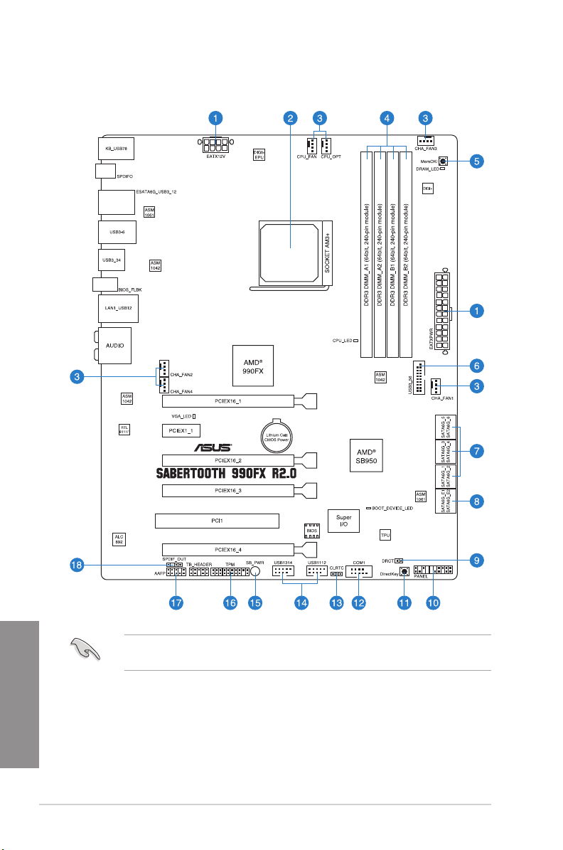
1.2.2 Motherboard layout
Chapter 1
1-6
Refer to 1.2.9 Internal connectors and 2.3.1 Rear I/O connection for more information
about rear panel connectors and internal connectors.
Chapter 1: Product introduction
Page 21

Layout contents
Connectors/Jumpers/Slots Page
1. ATX power connectors (24-pin EATXPWR, 8-pin EATX12V) 1-33
2. AM3+ CPU socket 1-8
3. CPU, chassis, and optional fan connectors (4-pin CPU_FAN,
4-pin CPU_OPT, 4-pin CHA_FAN1-4 )
4. DDR3 DIMM slots 1-9
5. MemOK! button 1-22
6. USB 3.0 connector (20-1 pin USB3_56) 1-27
7. AMD® Serial ATA 6.0 Gb/s connectors (7-pin SATA6G_1-6 [brown]) 1-26
8. ASmedia® Serial ATA 6.0 Gb/s connectors
(7-pin SATA6G_E12 [gray])
9. Direct connector (2-pin DRCT) 1-35
10. System panel connector (20-8 pin PANEL) 1-34
11. DirectKey button 1-23
12. Serial port connector (10-1 pin COM1) 1-30
13. Clear RTC RAM (3-pin CLRTC) 1-24
14. USB 2.0 connectors (10-1 pin USB1314, USB1112) 1-29
15. Standby power LED 1-25
16. TPM connector (20-1 pin TPM) 1-35
17. Front panel audio connector (10-1 pin AAFP) 1-32
18. Digital audio connector (4-1 pin SPDIF_OUT) 1-28
1-31
1-27
ASUS SABERTOOTH 990FX R2.0
Chapter 1
1-7
Page 22
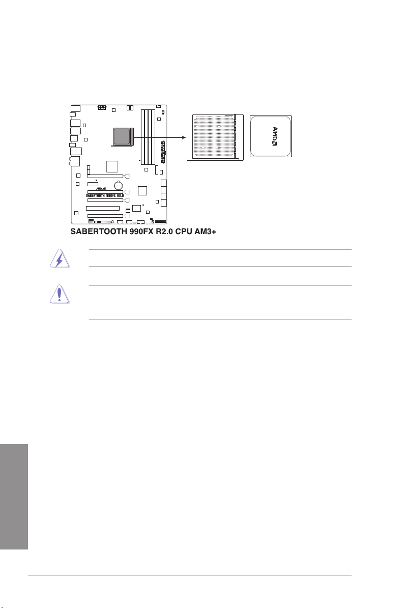
1.2.3 Central Processing Unit (CPU)
The motherboard comes with an AM3+ socket designed for AMD® FX Series CPU up to 8core, also compatible with AMD® socket AM3 for AMD® Phenom™ II/Athlon™ II/ Sempron™
100 Series Processors.
Ensure that all power cables are unplugged before installing the CPU.
The AM3+ socket has a different pinout design. Ensure that you use a CPU designed for
the AM3+/AM3 socket. The CPU ts in only one correct orientation. DO NOT force the CPU
into the socket to prevent bending the connectors on the socket and damaging the CPU!
Chapter 1
1-8
Chapter 1: Product introduction
Page 23
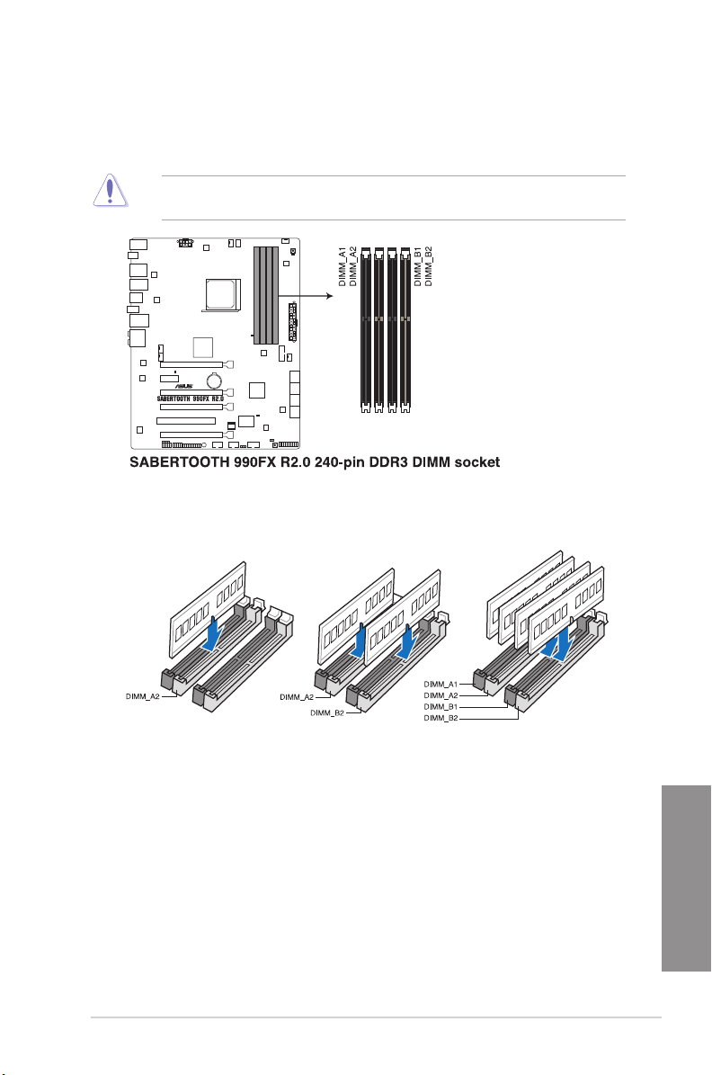
1.2.4 System memory
The motherboard comes with four Double Data Rate 3 (DDR3) Dual Inline Memory Modules
(DIMM) slots.
A DDR3 module is notched differently from a DDR or DDR2 module. DO NOT install a DDR
or DDR2 memory module to the DDR3 slot.
Recommended memory congurations
ASUS SABERTOOTH 990FX R2.0
Chapter 1
1-9
Page 24

Memory congurations
You may install 1GB, 2GB, 4GB, 8GB, and 16GB ECC, non-ECC and unbuffered DDR3
DIMMs into the DIMM sockets.
• Memory module with memory frequency higher than 2133 MHz and its corresponding
timing or the loaded DRAM OC Prole is not the JEDEC memory standard. The
stability and compatibility of these memory modules depend on the CPU’s capabilities
and other installed devices.
• You may install varying memory sizes in Channel A and Channel B. The system maps
the total size of the lower-sized channel for the dual-channel conguration. Any excess
memory from the higher-sized channel is then mapped for single-channel operation.
• Always install DIMMs with the same CAS latency. For optimal compatibility, weAlways install DIMMs with the same CAS latency. For optimal compatibility, we
recommend that you install memory modules of the same version or date code (D/C)
from the same vendor. Check with the retailer to get the correct memory modules.
• Due to the memory address limitation on 32-bit Windows OS, when you install 4GBDue to the memory address limitation on 32-bit Windows OS, when you install 4GB
or more memory on the motherboard, the actual usable memory for the OS can be
about 3GB or less. For effective use of memory, we recommend that you do any of the
following:
a) Use a maximum of 3GB system memory if you are using a 32-bit Windows OS.Use a maximum of 3GB system memory if you are using a 32-bit Windows OS.
b) Install a 64-bit Windows OS when you want to install 4GB or more on theInstall a 64-bit Windows OS when you want to install 4GB or more on thenstall a 64-bit Windows OS when you want to install 4GB or more on the
motherboard.
c) For more details, refer to the Microsoft® support site at http://support.microsoft.
com/kb/929605/en-us.
• This motherboard does not support DIMMs made up of 512Mb (64MB) chips or less
(Memory chip capacity counts in Megabit, 8 Megabit/Mb = 1 Megabyte/MB).
• The default memory operation frequency is dependent on its Serial Presence DetectThe default memory operation frequency is dependent on its Serial Presence Detect
(SPD), which is the standard way of accessing information from a memory module.
Under the default state, some memory modules for overclocking may operate at a
lower frequency than the vendor-marked value. To operate at the vendor-marked
or at a higher frequency, refer to section 3.4 Ai Tweaker menu for manual memory
frequency adjustment.
• For system stability, use a more efcient memory cooling system to support a fullFor system stability, use a more efcient memory cooling system to support a full
memory load (4 DIMMs) or overclocking condition.
Chapter 1
1-10
Chapter 1: Product introduction
Page 25

SABERTOOTH 990FX R2.0 Motherboard Qualied Vendors Lists (QVL)
DDR3 2400 MHz capability
Vendors Part No. Size SS/DSChip
G.SKILL F3-19200CL10Q-32GBZHD(XMP) 32GB
G.SKILL F3-19200CL11Q-16GBZHD(XMP) 16GB
G.SKILL F3-19200CL11Q-16GBZHD(XMP) 16GB
G.SKILL F3-19200CL9Q-16GBZMD(XMP) 16GB
GEIL GOC316GB2400C11QC(XMP) 16GB
Transcend TX2400KLU-4GK (381850)(XMP) 2GB DS - - - 1.65 •
Transcend TX2400KLU-4GK(374243)(XMP) 2GB DS - - - 1.65 •
DS - - 10-12-
(4x8GB)
DS - - 11-11-11-31 1.65 • •
(4x4GB)
DS - - 11-11-11-31 1.65 • •
(4x4GB)
DS - - 9-11-11-31 1.65 •
(4x4GB)
DS - - 11-11-11-30 1.65 •
(4x4GB)
Brand
Chip
Timing Voltage DIMM socket
NO.
12-31
1.65 • •
DDR3 2200 MHz capability
Vendors Part No. Size SS/DSChip
G.SKILL F3-17600CL7D-4GBFLS(XMP) 4G
GEIL GET34GB2200C9DC(XMP) 4GB
KINGMAX FLKE85F-B8KJAA-FEIS(XMP) 4GB
DS - - 7-10-10-28 1.65 • • •
(2x2G)
DS - - 9-10-9-28 1.65 • • •
(2x2GB)
DS Kingmax N/A - - • •
(2x2GB)
Brand
Chip
Timing Voltage DIMM socket
NO.
support (Optional)
1 2 4
support (Optional)
1 2 4
ASUS SABERTOOTH 990FX R2.0
Chapter 1
1-11
Page 26

DDR3 2133 MHz capability
Vendors Part No. Size SS/DSChip Brand Chip
CORSAIR CMT4GX3M2A2133C9
CORSAIR CMT4GX3M2B2133C9
CORSAIR CMT4GX3M2B2133C9
G.SKILL F3-17000CL11Q2-64G
G.SKILL F3-17000CL9Q-16GB
G.SKILL F3-17066CL9D-8GBP
G.SKILL F3-17066CL9Q-16GBT
KINGSTON KHX2133C11D3K4/16
KINGSTON KHX2133C11D3T1K2/
OCZ OCZ3XTEP2133C9L
Patriot PVV34G2133C9K
Patriot PXD38G2133C11K
Team TXD34096M2133HC9
(XMP)
(Ver7.1)(XMP)
(XMP)
BZLD(XMP)
ZH(XMP)
ID(XMP)
DD(XMP)
GX(XMP)
16GX(XMP)
V4GK
(XMP)
(XMP)
N-L(XMP)
4GB
(2x2GB)
4GB
(2x2GB)
4GB
(2x2GB)
64GB
(8x8GB)
16GB
(4x4GB)
8GB
(2x4GB)
16GB
(4x4GB)
16GB
(4x4GB)
16GB
(2x8GB)
2GB DS - - 7-7-7-201.65 • •
4GB
(2x2GB)
8GB
(2x4GB)
4GB DS SAMSUNG K4B2G
DS - - 9-10-
DS - - 9-9-9-241.5 • • •
DS - - 9-10-
DS - - 11-11-
DS - - 9-11-
DS - - 9-9-9-241.65 • •
DS - - 9-9-9-241.65 • •
DS - - 11-12-
DS - - 9-9-9-
DS - - 9-11-
DS - - 9-9-9-
Timing Voltage DIMM socket
NO.
1.65 • • •
9-24
1.5 • • •
9-27
1.5 • •
11-30
1.65 • • •
10-28
1.65 • • •
11-30
1.6 • • •
24
1.66 • •
9-27
1.65 • • •
24
9-9-9-
0846D
1.65 • • •
24
support (Optional)
1 2 4
Chapter 1
1-12
Chapter 1: Product introduction
Page 27

DDR3 2000 MHz capability
Vendors Part No. Size SS/DSChip
A-DATA AX3U2000GB2G9B
(XMP)
A-DATA AX3U2000GC4G9B
(XMP)
AEXEA AXA3ES2G2000LG
28V(XMP)
AEXEA AXA3ES4GK2000L
G28V(XMP)
Apacer 78.AAGD5.9KD(XMP) 6GB
Asint SLA302G08-ML2HB
(XMP)
CORSAIR CMT6GX3M3A2000
C8(XMP)
CORSAIR CMZ4GX3M2A2000C
10(Ver 5.12)(XMP)
G.SKILL F3-16000CL9D-4GB
RH(XMP)
G.SKILL F3-16000CL9D-4GB
TD(XMP)
Patriot PX7312G2000ELK
(XMP)
Team TXD32048M2000C9
(XMP)
Team TXD32048M2000C9
-L(XMP)
Team TXD32048M2000C9
-L(XMP)
2GB DS - - 9-11-
4GB DS - - 9-11-
2GB DS - - - 1.65 • • •
4GB
(2x2GB)
(3x2GB)
4GB DS Hynix H5TQ2G8
6GB
(3x2GB)
4GB
(2x2GB)
4GB
(2x2GB)
4GB
(2x2GB)
12GB
(3x4GB)
2GB DS Team T3D128
2GB DS Team T3D128
2GB DS Team T3D128
Brand
DS - - - 1.65 • • •
DS - - 9-9-9-27- • •
DS - - 8-9-8-241.65 • • •
SS - - 10-10-
DS - - 9-9-9-241.65 • •
DS - - 9-9-9-241.65 • •
DS - - 9-11-
Chip NO. Timing Voltage DIMM socket support
1.55~1.75 • •
9-27
1.55~1.75 • •
9-27
9-9-9-
3BFRH9C
8RT-20
8LT-20
8RT-20
- • •
27
1.5 • •
10-27
1.65 • •
9-27
9-9-9-241.5 • •
9-9-9-241.5 • •
9-9-9-241.6 • •
(Optional)
1 2 4
ASUS SABERTOOTH 990FX R2.0
Chapter 1
1-13
Page 28

DDR3 1866 MHz capability
Vendors Part No. Size SS/DSChip
A-DATA AX3U1866GC4G9B
CORSAIR CMD16GX3M4A1866 C9
CORSAIR CMD8GX3M2A1866C9
CORSAIR CMT32GX3M4X1866C9
CORSAIR CMZ16GX3M4X1866C9R
CORSAIR CMZ8GX3M2A1866C9
Crucial BLE4G3D1869DE1XT0.1
G.SKILL F3-14900CL10Q2-64GB
G.SKILL F3-14900CL9Q-16GBXL
G.SKILL F3-14900CL9Q-16GBZL
Kingston KHX1866C9D3K2/8GX
Patriot PXD38G1866ELK(XMP) 8GB
Patriot PXD38G1866ELK(XMP) 8GB
Team TXD34096M1866HC9K
(XMP)
(Ver4.13)(XMP)
(Ver4.13)(XMP)
(Ver3.23)(XMP)
(Ver8.16)(XMP)
(XMP)
6FMD(XMP)
ZLD(XMP)
(XMP)
(XMP)
(XMP)
-L(XMP)
4GB DS - - 9-11-9-27 1.55~
16GB
DS - - 9-10-9-27 1.5 • • •
(4x4GB)
8GB
DS - - - 1.5 • •
(2x4GB)
32GB
DS - - 9-10-9-27 1.5 • •
(4x8GB)
16GB
DS - - 9-10-9-27 1.5 • • •
(4x4GB)
8GB
DS - - 9-10-9-27 1.5 • • •
(2x4GB)
4GB DS - - 9-9-9-27 1.5 • • •
64GB
DS - - 10-11-
(8x8GB)
16GB
DS - - 9-10-9-28 1.5 • •
(4x4GB)
16GB
DS - - 9-10-9-28 1.5 • •
(4x4GB)
8GB
DS - - - 1.65 • • •
(2x4GB)
DS - - 9-11-9-27 1.65 • • •
(2x4GB)
DS - - 9-11-9-27 1.65 • • •
(2x4GB)
4GB DS Hynix H5TC2G8
Chip NO. Timing Voltage DIMM socket
Brand
1.75
10-30
9-11-9-27 1.65 • • •
3BFRH9A
1.5 • •
support (Optional)
1 2 4
• •
DDR3 1800 MHz capability
Vendors Part No. Size SS/DSChip
G.SKILL F3-14400CL9D-
Chapter 1
1-14
4GBRL(XMP)
Chip
Brand
4GB
DS - - 9-9-9-24 1.6 • • •
(2x2GB)
Timing Voltage DIMM socket support
NO.
Chapter 1: Product introduction
(Optional)
1 2 4
Page 29

DDR3 1600 MHz capability
Vendors Part No. Size SS/DSChip
A-DATA AM2U16BC2P1 2GB SS A-DATA 3CCD-
A-DATA AM2U16BC4P2 4GB DS A-DATA 3CCD-
A-DATA AX3U1600GC4G9(XMP) 4GB DS - - - 1.55~
A-DATA AX3U1600PC4G8(XMP) 4GB DS - - 8-8-8-24 1.55~
AEXEA AXA3PS4GK1600S18V
AMD AP38G1608U2K(XMP) 8GB
Asint SLA302G08-
Asint SLA302G08-
Asint SLA302G08-EGN1C 4GB DS ASint 302G08-
Asint SLB304G08-EGN1B 8GB DS ASint 304G08-
Asint SLZ302G08-EGN1C 2GB SS ASint 302G08-
Asint SLZ3128M8-
ATP AQ12M64B8BKK0S 4GB DS SAMSUNG K4B2G
CORSAIR CMG4GX3M2A1600C6 4GB
CORSAIR CML16GX3M4X1600C8
CORSAIR CMP6GX3M3A1600C8
CORSAIR CMP6GX3M3A1600C8
CORSAIR CMX6GX3M3C1600C7
CORSAIR CMZ16GX3M4A1600C9
CORSAIR CMZ8GX3M2A1600C8
CORSAIR CMZ8GX3M2A1600C9
CORSAIR CMZ8GX3M4X1600C9
CORSAIR HX3X12G1600C9(XMP) 12GB
Crucial BL12864BN1608.8FF
(XMP)
EGG1C(XMP)
EGJ1C(XMP)
EGJ1D(XMP)
(Ver 2.12)(XMP)
(XMP)
(XMP)
(XMP)
(XMP)
(XMP)
(XMP)
(Ver 2.12)(XMP)
(XMP)
4GB
DS - - - 1.65 • • •
(2x2GB)
DS - - 9-9-9-28 1.65 • • •
(2x4GB)
4GB DS Asint 302G08-
4GB DS Asint 302G08-
2GB DS Asint 3128M8-
DS - - 6-6-6-18 1.65 • • •
(2x2GB)
16GB
DS - - Heat-Sink
(4x4GB)
6GB
DS - - 8-8-8-24 1.65 • • •
(3x2GB)
6GB
DS - - 8-8-8-24 1.65 • • •
(3x2GB)
6GB
DS - - 7-8-7-20 1.65 • • •
(3x2GB)
16GB
DS - - 9-9-9-24 1.5 • • •
(4x4GB)
8GB
DS - - 8-8-8-24 1.5 • • •
(2x4GB)
8GB
DS - - 9-9-9-24 1.5 • • •
(2x4GB)
8GB
SS - - 9-9-9-24 1.5 • • •
(4x2GB)
DS - - 9-9-9-24 1.6 • • •
(6x2GB)
2GB
SS - - 8-8-8-24 1.65 • • •
(2x1GB)
Chip NO. Timing Voltage DIMM socket
Brand
- - • • •
1509A
- - • • •
1509A
9-9-9-27 - • • •
GG1C
9-9-9-27 - • •
GJ1C
- - • • •
GN1C
- - • • •
GN1B
- - • • •
GN1C
- - • • •
GJ1D
- NO • • •
08460
Package
1.75
1.75
1.5 • • •
(continued on the next page)
support
(Optional)
1 2 4
• • •
• • •
Chapter 1
ASUS SABERTOOTH 990FX R2.0
1-15
Page 30

DDR3 1600 MHz capability
Vendors Part No. Size SS/DSChip
Crucial BLT4G3D1608DT1
EK Memory EKM324L28BP8-I1
EK Memory EKM324L28BP8-I1
Elixir M2X2G64CB88G7
Elixir M2X4G64CB8HG5
G.SKILL F3-12800CL7D-8G
G.SKILL F3-12800CL7Q-16G
G.SKILL F3-12800CL8D-8G
G.SKILL F3-12800CL9D-8G
G.SKILL F3-12800CL9D-8G
G.SKILL F3-12800CL9Q-16
G.Skill F3-12800CL9Q-16
GEIL GET316GB1600C9
GEIL GUP34GB1600C7D
GoodRam GR1600D364L9/2G 2GB DS Good
KINGMAX FLGE85F-C8KL9A
KINGMAX FLGF65F-C8KL9A
KINGSTON KHX1600C9D3K2/4
KINGSTON KHX1600C9D3K3/
KINGSTON KHX1600C9D3K3/6G
Chapter 1
KINGSTON KHX1600C9D3K3/6G
Kingston KHX1600C9D3K4/
KINGSTON KHX1600C9D3K6/
Kingston KHX1600C9D3K8/
TX0.16FM(XMP)
6(XMP)
6(XMP)
N-DG (XMP)
N-DG (XMP)
BRH (XMP)
BXH (XMP)
BECO (XMP)
BRL (XMP)
BSR2 (XMP)
GBXL (XMP)
GBZL (XMP)
QC(XMP)
C(XMP)
(XMP)
(XMP)
GX(XMP)
12GX(XMP)
X(XMP)
X(XMP)
16GX(XMP)
24GX(XMP)
32GX(XMP)
Chip NO. Timing Voltage DIMM socket
Brand
4GB DS - - 8-8-8-24 1.5 • • •
4GB
DS - - 9 - • • •
(2x2GB)
4GB
DS - - 9 - • • •
(2x2GB)
2GB SS Elixir N2CB2
4GB DS Elixir N2CB2G
8GB
DS - - 7-8-7-24 1.6 • • •
(2x4GB)
16GB
DS - - 7-8-7-24 1.6 • • •
(4x4GB)
8GB
DS - - 8-8-8-24 1.35 • •
(2x4GB)
8GB
DS - - 9-9-9-24 1.5 • • •
(2x4GB)
8GB
DS - - 9-9-9-24 1.25 • • •
(2x4GB)
16GB
DS - - 9-9-9-24 1.5 • • •
(4x4GB)
16GB
DS - - 9-9-9-24 1.5 • • •
(4x4GB)
16GB
DS - - 9-9-9-28 1.6 • • •
(4x4GB)
4GB
DS - - 7-7-7-24 1.6 • • •
(2x2GB)
Ram
2GB SS KING
4GB DS KING
4GB
(2x2GB)
12GB
(3x4GB)
6GB
(3x2GB)
6GB
(3x2GB)
16GB
(4x4GB)
24GB
(6x4GB )
32GB
(8x4GB)
MAX
MAX
DS - - - 1.65 • • •
DS - - - 1.65 • • •
DS - - 9 1.65 • • •
DS - - 9 1.65 • • •
DS 9-9-9-24 1.65 • • •
DS - - 9 1.65 • •
DS - - 9-9-9-27 1.65 • • •
9-9-9-28 - • • •
G80GNDG
9-9-9-28 - • • •
80GNDG
GF1008
- - • • •
KC-JN
N/A 9-9-9-28 - • • •
N/A 9-9-9-28 - • • •
support (Optional)
1 2 4
1-16
(continued on the next page)
Chapter 1: Product introduction
Page 31

DDR3 1600 MHz capability
Vendors Part No. Size SS/DSChip
KINGSTON KHX1600C9D3LK2/
Kingston KHX1600C9D3LK2/
KINGSTON KHX1600C9D3P1K2/8G8GB
KINGSTON KHX1600C9D3T1BK3/1
KINGSTON KHX1600C9D3T1K3/
KINGSTON KHX1600C9D3X2K2/
KINGTIGER KTG2G1600PG3(XMP) 2GB DS - - - - • • •
Mushkin 996805(XMP) 4GB
Mushkin 998805(XMP) 6GB
OCZ OCZ3BE1600C8LV4GK 4GB
Patriot AE32G1609U1-U 2GB SS AMD 23EY4587
Patriot AE34G1609U2-U 4GB DS AMD 23EY4587
Patriot PGD316G1600ELK
Patriot PGD38G1600ELK
Patriot PGS34G1600LLKA 4GB
Patriot PGS34G1600LLKA2 4GB
Patriot PVV38G1600LLK
Patriot PX7312G1600LLK
SanMax SMD-4G68HP-16KZ 4GB DS Hynix H5TQ2G83
SanMax SMD-4G68NG-16KK 4GB DS ELPIDA J2108BDB
Silicon
Power
Silicon
Power
Team TED34096M1600HC11 4GB DS Team T3D2568E
Team TXD31024M1600C8-D
Team TXD32048M1600C7-L
4GX (XMP)
8GX (XMP)
2GX(XMP)
6G X(XMP)
4G X(XMP)
(XMP)
(XMP)
(XMP)
(XMP)
SP002GBLTU160V02
(XMP)
SP004GBLTU160V02
(XMP)
(XMP)
(XMP)
4GB
DS - - - 1.35 • • •
(2x2GB)
8GB
DS - - 9-9-9-24 1.35 • • •
(2x4GB)
DS - - 9 1.5 • •
(2x4GB)
12GB
DS - - 9 1.65 • •
(3x4GB)
6GB
DS - - 9 1.65 • • •
(3x2GB)
4GB
DS - - 9 1.65 • • •
(2x2GB)
DS - - 6-8-6-24 1.65 • • •
(2x2GB)
DS - - 6-8-6-24 1.65 • • •
(3x2GB)
DS - - 8-8-8 1.65 • •
(2x2GB)
16GB
DS - - - 1.65 • • •
(2x8GB)
8GB
DS - - 9-9-9-24 1.65 • • •
(2x4GB)
DS - - 7-7-7-20 1.7 • • •
(2x2GB)
DS - - 8-8-8-24 1.7 • •
(2x2GB)
8GB
DS - - 8-9-8-24 1.65 • • •
(2x4GB)
12GB
DS - - 8-9-8-24 1.65 • • •
(3x4GB)
2GB SS S-POWER 20YT5NG 9-11-
4GB DS S-POWER 20YT5NG 9-9-9-24 1.5 • • •
1GB SS Team T3D1288R
2GB DS Team T3D1288L
Chip NO. Timing Voltage DIMM socket
Brand
MB6H
MB6H
BFRPBC
G-GN-F
T-16
T-16
T-16
- 1.5 • • •
- 1.5 • • •
- 1.5 • • •
- - • • •
1.5 • • •
11-28
- - • • •
8-8-8-24 1.65 • • •
7-7-7-24 1.65 • •
support
(Optional)
1 2 4
(continued on the next page)
Chapter 1
ASUS SABERTOOTH 990FX R2.0
1-17
Page 32

DDR3 1600 MHz capability
Vendors Part No. Size SS/DSChip
Team TXD32048M1600HC8-
Team TXD34096M1600HC9-
Transcend JM1600KLN-8GK 8GB
Transcend TS256MLK64V6N 2GB SS Transcend K4B2G084 6C- - • • •
Transcend TS512MLK64V6N 4GB DS MICRON D9PFJ - - • • •
Transcend TS512MLK64V6N 4GB DS Transcend K4B2G084 6C- - • • •
DDR3 1333 MHz capability
Vendors Part No. Size SS/DS Chip
A-DATA AD63I1B0823EV 2GB SS A-DATA 3CCA-
A-DATA AD63I1C1624EV 4GB DS A-DATA 3CCA-
A-DATA AXDU1333GC2G
A-DATA SU3U1333W8G9
Apacer 78.A1GC6.9L1 2GB DS Apacer AM5D580
Apacer 78.B1GDE.9L10C 4GB DS Apacer AM5D590
CORSAIR CMX8GX3M2A133
CORSAIR TW3X4G1333C9A 4GB
G.SKILL F3-10600CL9D-
G.SKILL F3-10666CL9D-
G.SKILL F3-10666CL9D-
Chapter 1
GEIL GB34GB1333C7DC 4GB
GEIL GET316GB1333C9 QC16GB
GEIL GG34GB1333C9DC 4GB
GEIL GG34GB1333C9DC 4GB
D (XMP)
D (XMP)
9(XMP)
(XMP)
3C9(XMP)
4G BNT
8G BRL
8G BXL
Chip NO. Timing Voltage DIMM socket
Brand
2GB DS Team T3D1288R
4GB DS Hynix H5TC2G83
DS Transcend TK483PC W3- - • •
(2x4GB)
Brand
2GB SS - - 9-9-9-24 1.25~
8GB DS ELPIDA J4208BA
8GB
(2x4GB)
(2x2GB)
4GB
(2x2GB)
8GB
(2x4GB)
8GB
(2x4GB)
(2x2GB)
(4x4GB)
(2x2GB)
(2x2GB)
DS - - 9-9-9-24 1.5 • • •
DS - - 9-9-9-24 1.5 • •
DS G.SKILL D3 128M8
DS - - 9-9-9-24 1.5 • • •
DS - - 9-9-9-24 1.5 • • •
DS GEIL GL1L128M
DS - - 9-9-9-24 1.5 • •
DS GEIL GL1L128M8
DS GEIL GL1L128M8
T-16
BFRH9A
Chip NO. Timing Voltage DIMM socket
1509 A
1509 A
SE-DJ-F
8FEQSBG
8CEHSBG
CE9 2GB
88BA15FW
8BA115FW
8BA15B
8-8-8-24 1.65 • • •
9-9-9-24 1.5 • • •
- - • • •
- - • • •
1.35
- - • • •
9 - • • •
9 - • • •
9-9-9-24 1.5 • • •
7-7-7-24 1.5 • • •
9-9-9-24 1.3 • • •
9-9-9-24 1.3 • • •
(continued on the next page)
support
(Optional)
1 2 4
support (Optional)
1 2 4
• • •
1-18
Chapter 1: Product introduction
Page 33

DDR3 1333 MHz capability
Vendors Part No. Size SS/DSChip
GEIL GVP34GB1333C
GEIL GVP38GB1333C
GEIL GVP38GB1333C
Hynix HMT125U6TFR
KINGMAX FLFE85F-B8KL9 2GB DS KINGMAX KFB8FNLXL-
KINGMAX FLFE85F-C8KL9 2GB SS KINGMAX KFC8FNLBF-
KINGMAX FLFE85F-C8KL9 2GB SS KINGMAX KFC8FNLXF-
KINGMAX FLFE85F-C8KM9 2GB SS Kingmax KFC8FNMXF-
KINGMAX FLFF65F-C8KL9 4GB DS KINGMAX KFC8FNLBF-
KINGMAX FLFF65F-C8KL9 4GB DS KINGMAX KFC8FNLXF-
KINGMAX FLFF65F-C8KM9 4GB DS Kingmax KFC8FNMXF-
KINGSTON KVR1333D3E9S/4G4GB DS Elpida J2108ECSE-
KINGSTON KVR1333D3N9/2G 2GB DS Kingston D1288JPNDP
KINGSTON KVR1333D3N9H/8G8GB DS ELPIDA J4208EASE-
KINGSTON KVR1333D3N9K2/ 4G4GB
KINGSTON KVR1333D3S8N9/ 2G2GB SS Micron IFD77 D9LGK - 1.5 • • •
MICRON MT16KTF51264AZ-
MICRON MT8JTF25664AZ-
MICRON MT8KTF25664AZ-
OCZ OCZ3G1333LV4GK 4GB
OCZ OCZ3G1333LV8GK 8GB
OCZ OCZ3G1333LV8GK 8GB
9DC
7QC
9DC
8A- H9
1G6M1
1G4M1
1G6M1
4GB
(2x2GB)
8GB
(4x2GB)
8GB
(2x4GB)
2GB DS Hynix H5TC1G83TFR - - • • •
(2x2GB)
4GB DS MICRON D9PFJ - - • • •
2GB SS MICRON D9PFJ - - • • •
2GB SS MICRON D9PFJ - - • • •
(2x2GB)
(2x4GB)
(2x4GB)
Brand
DS - - 9-9-9-24 1.5 • •
DS - - 7-7-7-24 1.5 • • •
DS - - 9-9-9-24 1.5 • • •
DS KINGSTON D1288JEMF
DS - - 9-9-9 1.65 • •
DS - - 9-9-9 1.65 • • •
DS - - 9-9-9 1.65 • •
Chip NO. Timing Voltage DIMM socket
BNF-15A
GXX-12A
DXX-15A
BXX-15A
GXX-12A
DXX-15A
BXX-15A
DJ-F
LD9U
DJ-F
PGD9U
- - • • •
- - • • •
- - • • •
- - • • •
- - • • •
- - • • •
- - • • •
9 1.5 • • •
9 1.5 • • •
9-9-9-24 1.5 • • •
- 1.5 • • •
support
(Optional)
1 2 4
(continued on the next page)
ASUS SABERTOOTH 990FX R2.0
Chapter 1
1-19
Page 34

DDR3 1333 MHz capability
Vendors Part No. Size SS/DSChip
OCZ OCZ3RPR1333C9L
SAMSUNG M378B1G73AH0-
SAMSUNG M378B5273CH0-
SAMSUNG M378B5673FH0-
Transcend JM1333KLN-2G 2GB SS Transcend TK483PCW3 - - • •
Transcend JM1333KLN-2G
Transcend JM1333KLN-4G 4GB DS Transcend TK483PCW3 - - • • •
Transcend JM1333KLN-4G (
Transcend TS256MLK64V3N
Transcend TS256MLK64V3N
Transcend TS256MLK64V3N
Transcend TS256MLK64V3NL 2GB SS Hynix H5TQ2G83CF
Transcend TS512MLK64V3N
V8GK
CH9
CH9
CH9
(582670)
583782 )
(585541 )
(566577)
(574206)
(574831)
8GB
(2x4GB)
8GB DS SAMSUNG K4B4G0846A
4GB DS SAMSUNG K4B2G0846C K4B2G
2GB DS SAMSUNG K4B1G0846F - - • • •
2GB SS Micron ICD77 C9LGK - - •
4GB DS Transcend TK483PCW3 9 - • •
2GB SS Micron ICD77 D9LGK 9 - • • •
2GB SS Hynix H5TQ2G83B FR9 - • • •
2GB SS Micron D9LGK 9 - • • •
4GB DS Micron D9LGK 9 - •
Brand
DS - - 9-9-9 1.65 • •
Chip NO. Timing Voltage DIMM socket
-HCH9
RH9C
- - • • •
- • • •
0846C
- - •
support
(Optional)
1 2 4
Chapter 1
1-20
Chapter 1: Product introduction
Page 35

Side(s): SS - Single-sided DS - Double-sided DIMM support:
(1) Supports one (1) module inserted into any slot as Single-channel memory
conguration. We suggest that you install the module into A2 slot.
(2) Supports two (2) modules inserted into either the blue slots or the black slots as one
pair of Dual-channel memory conguration. We suggest that you install the modules
into slots A2 and B2 for better compatibility.
(4) Supports four (4) modules inserted into both the blue and black slots as two pairs of
Dual-channel memory conguration.
• ASUS exclusively provides hyper DIMM support function.
• Hyper DIMM support is subject to the physical characteristics of individual CPUs. LoadHyper DIMM support is subject to the physical characteristics of individual CPUs. Load
the X.M.P. or D.O.C.P. settings in the BIOS for the hyper DIMM support.
• Visit the ASUS website for the latest QVL.Visit the ASUS website for the latest QVL.
ASUS SABERTOOTH 990FX R2.0
Chapter 1
1-21
Page 36

1.2.5 Expansion slots
Unplug the power cord before adding or removing expansion cards. Failure to do so may
cause you physical injury and damage motherboard components.
Slot No. Slot Description
1 PCIe 2.0 x16_1 slot (single at x16, dual at x16/x16, triple at x16/x8/x8 mode)
2 PCIe 2.0 x1_1 slot
3 PCIe 2.0 x16_2 slot
4 PCIe 2.0 x16_3 slot
5 PCI slot
Chapter 1
6 PCIe 2.0 x16_4 slot
1-22
Chapter 1: Product introduction
Page 37

VGA
conguration
Single VGA/
PCIe card
Dual VGA/PCIe
card
PCIe
2.0_x16_1
x16
(Recommend for
single VGA)
x16 x4 x16 x1
PCI Express operating mode
PCIe
2.0_x16_2
PCIe
2.0x16_3
x4 N/A x8
PCIe
2.0x16_4
3-way SLI x16 x4 x8 x8
• In single VGA card mode, use the PCIe 2.0 x16_1 slot (beige) for a PCI Express x16
graphics card to get better performance.
• In CrossFireX™ or SLI™ mode, use the PCIe 3.0 x16_1 and PCIe 3.0 x16_3 slots for
PCI Express x16 graphics cards to get better performance.
• In 3-way SLI mode, use the PCIe 3.0 x16_1/PCIe 3.0 x16_3/PCIe 3.0 x16_4 slots for
PCI Express x16 graphic cards to get better performance.
• We recommend that you provide sufcient power when running CrossFireX™ or SLI™
mode.
• Connect a chassis fan to the motherboard connector labeled CHA_FAN1/2 when
using multiple graphics cards for better thermal environment.
IRQ assignments for this motherboard
A B C D E F G H
PCIe x16_1 shared – – – – – – –
PCIe x16_2 shared – – – – – – –
PCIe x16_3 shared – – – – – – –
PCIe x16_4 – – – – shared – – –
PCIe x1_1 – – – – shared – – –
ASM eSATA – – – – shared – – –
ASM SATA [Gray] – – – – – – shared –
ASM USB3_12 – – – – – – shared –
ASM 1042 (Front) – – – – – – – shared
ASM USB3_3 shared – – – – – – –
Realtek 8111F (LAN) – – – – – shared – –
Onchip SATA [Brown] – – – shared – – – –
Onchip Audio shared – – – – – – –
Onchip USB2_1-5 – shared – – – – – –
Onchip USB2_6-8 – – – – – shared – –
Onchip USB2_11-14 – – – – – – – shared
Chapter 1
ASUS SABERTOOTH 990FX R2.0
1-23
Page 38

1.2.6 Onboard buttons
Onboard buttons allow you to ne-tune performance when working on a bare or open-
case system. This is ideal for overclockers and gamers who continually change settings to
enhance system performance.
1. MemOK! button
Installing DIMMs that are not compatible with the motherboard may cause system
boot failure, and the DRAM_LED near the MemOK! switch lights continuously. Press
and hold the MemOK! button until the DRAM_LED starts blinking to begin automatic
memory compatibility tuning for successful boot.
Chapter 1
• Refer to section 1.2.8 Onboard LEDs for the exact location of the DRAM_LED.
• The DRAM_LED also lights up when the DIMM is not properly installed. Turn off theThe DRAM_LED also lights up when the DIMM is not properly installed. Turn off the
system and reinstall the DIMM before using the MemOK! function.
• The MemOK! switch does not function under Windows™ OS environment.The MemOK! switch does not function under Windows™ OS environment.
• During the tuning process, the system loads and tests failsafe memory settings. ItDuring the tuning process, the system loads and tests failsafe memory settings. It
takes about 30 seconds for the system to test one set of failsafe settings. If the test
fails, the system reboots and test the next set of failsafe settings. The blinking speed
of the DRAM_LED increases, indicating different test processes.
• Due to memory tuning requirement, the system automatically reboots when eachDue to memory tuning requirement, the system automatically reboots when each
timing set is tested. If the installed DIMMs still fail to boot after the whole tuning
process, the DRAM_LED lights continuously. Replace the DIMMs with ones
recommended in the Memory QVL (Qualied Vendors Lists) in this user manual or on
the ASUS website at www.asus.com.
• If you turn off the computer and replace DIMMs during the tuning process, the systemIf you turn off the computer and replace DIMMs during the tuning process, the system
continues memory tuning after turning on the computer. To stop memory tuning, turn
off the computer and unplug the power cord for about 5–10 seconds.
• If your system fails to boot up due to BIOS overclocking, press the MemOK! switchIf your system fails to boot up due to BIOS overclocking, press the MemOK! switch
to boot and load the BIOS default settings. A message will appear during POST
reminding you that the BIOS has been restored to its default settings.
• We recommend that you download and update to the latest BIOS version from theWe recommend that you download and update to the latest BIOS version from the
ASUS website at www.asus.com after using the MemOK! function.
1-24
Chapter 1: Product introduction
Page 39

2. DirectKey button
This feature allows your system to go to the BIOS Setup program with the press of
a button. With DirectKey, you can enter the BIOS anytime without having to press
the <Del> key during POST. It also allows you to turn on or turn off your system and
conveniently enter the BIOS during boot-up.
Ensure to save your data before using the DirectKey button.
• When the system is on and you press the DirectKey button, your system will shut
down. Press the DirectKey button again or the Power-on button to reboot and enter
the BIOS directly.
• Turn off your system using the power-on button to allow your system to go through
POST (without entering the BIOS) when you reboot your system.
• Refer to section 3.7 Boot Menu for details about setting the DirectKey default
function.
ASUS SABERTOOTH 990FX R2.0
Chapter 1
1-25
Page 40

1.2.7 Jumpers
1. Clear RTC RAM (3-pin CLRTC)
This jumper allows you to clear the Real Time Clock (RTC) RAM in CMOS. You can
clear the CMOS memory of date, time, and system setup parameters by erasing
the CMOS RTC RAM data. The onboard button cell battery powers the RAM data in
CMOS, which include system setup information such as system passwords.
To erase the RTC RAM:
1. Turn OFF the computer and unplug the power cord.
2. Move the jumper cap from pins 1-2 (default) to pins 2-3. Keep the cap on pins 2-3 for
about 5-10 seconds, then move the cap back to pins 1-2.
3. Plug the power cord and turn ON the computer.
4. Hold down the <Del> key during the boot process and enter BIOS setup to re-enter
data.
Chapter 1
1-26
Except when clearing the RTC RAM, never remove the cap on CLRTC jumper default
position. Removing the cap will cause system boot failure!
• If the steps above do not help, remove the onboard battery and move the jumper
again to clear the CMOS RTC RAM data. After the CMOS clearance, reinstall the
battery.
• You do not need to clear the RTC when the system hangs due to overclocking. For
system failure due to overclocking, use the C.P.R. (CPU Parameter Recall) feature.
Shut down and reboot the system so the BIOS can automatically reset parameter
settings to default values.
• Due to the chipset behavior, AC power off is required to enable C.P.R. function. You
must turn off and on the power supply or unplug and plug the power cord before
rebooting the system.
Chapter 1: Product introduction
Page 41

1.2.8 Onboard LEDs
1. POST State LEDs
The POST State LEDs provide the status of these key components during POST
(Power-On-Self Test): CPU, memory modules, VGA card, and hard disk drives. If an
error is found, the critical component’s LED stays lit up until the problem is solved.
2. Standby Power LED
The motherboard comes with a standby power LED. The green LED lights up to
indicate that the system is ON, in sleep mode, or in soft-off mode. This is a reminder
that you should shut down the system and unplug the power cable before removing or
plugging in any motherboard component. The illustration below shows the location of
the onboard LED.
ASUS SABERTOOTH 990FX R2.0
Chapter 1
1-27
Page 42

1.2.9 Internal connectors
1. AMD® Serial ATA 6.0 Gb/s connectors (7-pin SATA6G_1-6 [brown])
These connectors connect to Serial ATA 6.0 Gb/s hard disk drives via Serial ATA 6.0
Gb/s signal cables.
If you installed Serial ATA hard disk drives, you can create a RAID 0, 1, 5, and 10
conguration through the onboard AMD® SB950 chipset.
Chapter 1
1-28
• These connectors are set to [AHCI Mode] by default. If you intend to create a Serial
ATA RAID set using these connectors, set the SATA Mode item in the BIOS to [RAID
Mode]. Refer to section 3.5.4 SATA Conguration for details.
• Before creating a RAID set, refer to section 5.1 RAID congurations or the manual
bundled in the motherboard support DVD.
• When creating a RAID set, set the SATA_5-6 connectors to [IDE Mode] to ensure that
the system recognizes your ODD device.
• When using NCQ, set the SATA Mode in the BIOS toWhen using NCQ, set the SATA Mode in the BIOS to [AHCI Mode]. Refer to section
3.5.4 SATA Conguration for details.
• You must install WindowsYou must install Windows® XP Service Pack 3 or later versions before using Serial
ATA hard disk drives. The Serial ATA RAID feature is available only if you are using
Windows® XP SP3 or later versions.
Chapter 1: Product introduction
Page 43

2. ASMedia® Serial ATA 6.0 Gb/s connectors (7-pin SATA6G_E1-2 [gray])
These connectors connect to Serial ATA 6.0 Gb/s hard disk drives via Serial ATA 6.0
Gb/s signal cables.
3. USB 3.0 connector (20-1 pin USB3_56)
This connector is for the additional USB 3.0 ports, and complies with the USB 3.0
specicaton that supports up to 480 MBps connection speed. If the USB 3.0 front panel
cable is available from your system chassis, with this USB 3.0 connector, you can have
a front panel USB 3.0 solution.
ASUS SABERTOOTH 990FX R2.0
Chapter 1
1-29
Page 44

4. Digital audio connector (4-1 pin SPDIF_OUT)
This connector is for an additional Sony/Philips Digital Interface (S/PDIF) port. Connect
the S/PDIF Out module cable to this connector, then install the module to a slot
opening at the back of the system chassis.
The S/PDIF module is purchased separately.
Chapter 1
1-30
Chapter 1: Product introduction
Page 45

5. USB 2.0 connectors (10-1 pin USB1314, USB1112)
These connectors are for USB 2.0 ports. Connect the USB module cable to any of
these connectors, then install the module to a slot opening at the back of the system
chassis. These USB connectors comply with USB 2.0 specication that supports up to
48 MBps connection speed.
Never connect a 1394 cable to the USB connectors. Doing so will damage the
motherboard!
You can connect the front panel USB cable to the ASUS Q-Connector (USB, blue) rst, and
then install the Q-Connector (USB) to the USB connector onboard if your chassis supports
front panel USB ports.
The USB 2.0 module is purchased separately.
ASUS SABERTOOTH 990FX R2.0
Chapter 1
1-31
Page 46

6. Serial port connector (10-1 pin COM1)
This connector is for a serial (COM) port. Connect the serial port module cable to this
connector, then install the module to a slot opening at the back of the system chassis.
The COM module is purchased separately.
Chapter 1
1-32
Chapter 1: Product introduction
Page 47

7. CPU and chassis fan connectors
(4-pin CPU_FAN, 4-pin CPU_OPT, 4-pin CHA_FAN1-4)
Connect the fan cables to the fan connectors on the motherboard, ensuring that the
black wire of each cable matches the ground pin of the connector.
DO NOT forget to connect the fan cables to the fan connectors. Insufcient air ow inside
the system may damage the motherboard components. These are not jumpers! Do not
place jumper caps on the fan connectors!
• The CPU_FAN connector supports the CPU fan of maximum 1A (12 W) fan power.The CPU_FAN connector supports the CPU fan of maximum 1A (12 W) fan power.
• If you install two VGA cards, we recommend that you plug the rear chassis fan cableIf you install two VGA cards, we recommend that you plug the rear chassis fan cable
to the motherboard connector labeled CHA_FAN1 or CHA_FAN2 for better thermal
environment.
ASUS SABERTOOTH 990FX R2.0
Chapter 1
1-33
Page 48

8. Front panel audio connector (10-1 pin AAFP)
This connector is for a chassis-mounted front panel audio I/O module that supports
either HD Audio or legacy AC`97 audio standard. Connect one end of the front panel
audio I/O module cable to this connector.
• We recommend that you connect a high-denition front panel audio module to thisWe recommend that you connect a high-denition front panel audio module to this
connector to avail of the motherboard’s high-denition audio capability.
• If you want to connect a high-denition or an AC’97 front panel audio module to thisIf you want to connect a high-denition or an AC’97 front panel audio module to this
connector, set the Front Panel Type item in the BIOS setup to [HD] or [AC97].
Chapter 1
1-34
Chapter 1: Product introduction
Page 49

9. ATX power connectors (24-pin EATXPWR, 8-pin EATX12V)
These connectors are for ATX power supply plugs. The power supply plugs are
designed to t these connectors in only one orientation. Find the proper orientation and
push down rmly until the connectors completely t.
• For a fully congured system, we recommend that you use a power supply unitFor a fully congured system, we recommend that you use a power supply unit
(PSU) that complies with ATX 12 V Specication 2.0 (or later version) and provides a
minimum power of 350 W.
• DO NOT forget to connect the 4-pin/8-pin EATX12 V power plug. Otherwise, theDO NOT forget to connect the 4-pin/8-pin EATX12 V power plug. Otherwise, the
system will not boot.
• We recommend that you use a PSU with a higher power output when conguring aWe recommend that you use a PSU with a higher power output when conguring a
system with more power-consuming devices. The system may become unstable or
may not boot up if the power is inadequate.
• If you want to use two or more high-end PCI Express x16 cards, use a PSU withIf you want to use two or more high-end PCI Express x16 cards, use a PSU with
1000W power or above to ensure the system stability.
• If you are uncertain about the minimum power supply requirement for your system,If you are uncertain about the minimum power supply requirement for your system,
refer to the Recommended Power Supply Wattage Calculator at http://support.asus.
com/PowerSupplyCalculator/PSCalculator.aspx?SLanguage=en-us for details.
ASUS SABERTOOTH 990FX R2.0
Chapter 1
1-35
Page 50

10. System panel connector (20-8 pin PANEL)
This connector supports several chassis-mounted functions.
• System power LED (2-pin PLED)
This 2-pin connector is for the system power LED. Connect the chassis power LED
cable to this connector. The system power LED lights up when you turn on the system
power, and blinks when the system is in sleep mode.
• Hard disk drive activity LED (2-pin IDE_LED)
This 2-pin connector is for the HDD Activity LED. Connect the HDD Activity LED cable
to this connector. The IDE LED lights up or ashes when data is read from or written to
the HDD.
• System warning speaker (4-pin SPEAKER)
This 4-pin connector is for the chassis-mounted system warning speaker. The speaker
allows you to hear system beeps and warnings.
• ATX power button/soft-off button (2-pin PWRSW)
This connector is for the system power button. Pressing the power button turns
the system on or puts the system in sleep or soft-off mode depending on the BIOS
settings. Pressing the power switch for more than four seconds while the system is ON
turns the system OFF.
• Reset button (2-pin RESET)
This 2-pin connector is for the chassis-mounted reset button for system reboot without
turning off the system power.
Chapter 1
1-36
Chapter 1: Product introduction
Page 51

11. TPM connector (20-1 pin TPM)
This connector supports a Trusted Platform Module (TPM) system, which securely
store keys, digital certicates, passwords and data. A TPM system also helps enhance
network security, protect digital identities, and ensures platform integrity.
12. Direct Connector (2-pin DRCT)
This connector is for the chassis-mounted button that supports the DirectKey function.
Connect the button cable that supports DirectKey, from the chassis to this connector on
the motherboard.
Ensure that your chassis comes with the button cable that supports the DirectKey feature.
Refer to the technical documentation that came with the chassis for details.
ASUS SABERTOOTH 990FX R2.0
Chapter 1
1-37
Page 52

Chapter 1
1-38
Chapter 1: Product introduction
Page 53

Basic Installation
2.1 Building your PC system
2.1.1 Motherboard installation
The diagrams in this section are for reference only. The motherboard layout may vary with
models, but the installation steps are the same for all models.
1. Install the ASUS Q-Shield to the chassis rear I/O panel.
2
ASUS SABERTOOTH 990FX R2.0
Chapter 2
2-1
Page 54

2. Place the motherboard into the chassis, ensuring that its rear I/O ports are aligned to
the chassis’ rear I/O panel.
Chapter 2
2-2
Chapter 2: Getting started
Page 55

3. Place nine screws into the holes indicated by circles to secure the motherboard to the
chassis.
DO NOT overtighten the screws! Doing so can damage the motherboard.
ASUS SABERTOOTH 990FX R2.0
Chapter 2
2-3
Page 56

2.1.2 CPU installation
The AMD AM3+ socket is compatible with AMD AM3+ and AM3 processors. Ensure you
use a CPU designed for the AM3+ socket. The CPU ts in only one correct orientation. DO
NOT force the CPU into the socket to prevent bending the connectors on the socket and
damaging the CPU!
Chapter 2
1
2
3
2-4
Chapter 2: Getting started
Page 57

2.1.3 CPU heatsink and fan assembly installation
Apply the Thermal Interface Material to the
CPU heatsink and CPU before you install
the heatsink and fan if necessary.
To install the CPU heatsink and fan assembly
1
ASUS SABERTOOTH 990FX R2.0
Chapter 2
2-5
Page 58

2
3
Chapter 2
2-6
4
5
Chapter 2: Getting started
Page 59

2.1.4 DIMM installation
1
2
3
To remove a DIMM
B
ASUS SABERTOOTH 990FX R2.0
A
Chapter 2
2-7
Page 60

2.1.5 ATX Power connection
1
2
OR OR
Chapter 2
2-8
Chapter 2: Getting started
Page 61

2.1.6 SATA device connection
1
OR
2
OR
ASUS SABERTOOTH 990FX R2.0
Chapter 2
2-9
Page 62

2.1.7 Front I/O Connector
IDE_LED
POWER SW
RESET SW
IDE_LED-
IDE_LED+
PWR
Reset
Ground
Ground
To install ASUS Q-Connector
1
2
To install USB 2.0 connector To install front panel audio connector
AAFP
To install USB 3.0 connector
Chapter 2
2-10
USB 2.0
USB 3.0
Chapter 2: Getting started
Page 63

2.1.8 Expansion Card installation
To install PCIe x16 cards
To install PCIe x1 cards
ASUS SABERTOOTH 990FX R2.0
Chapter 2
2-11
Page 64

2.2 BIOS update utility
USB BIOS Flashback
USB BIOS Flashback allows you to easily update the BIOS without entering the existing
BIOS or operating system. Simply insert a USB storage device to the USB port, press the
USB BIOS Flashback button for three seconds, and the BIOS is updated automatically.
To use USB BIOS Flashback:
1. Place the bundled support DVD to the optical drive and install the USB BIOS
Flashback Wizard. Follow the onscreen instructions to complete the installation.
You can also download the BIOS from ASUS ofcial website www.asus.com. Rename the
le as ST990R20.CAP, and save it in the root directory of a USB storage device.
2. Insert the USB storage device to the USB Flashback port.
3. Launch the USB BIOS Flashback Wizard to automatically download the latest BIOS
version.
4. Press the BIOS Flashback button for three seconds until a ashing light appears, which
indicates that the BIOS Flashback function is enabled.
5. Wait until the light goes out, indicating that the BIOS updating process is completed.
Chapter 2
2-12
USB BIOS Flashback button
For more BIOS update utilities in BIOS setup, refer to the section 3.10 Updating BIOS.
• Do not unplug portable disk, power system, or press the CLR_CMOS button while
BIOS update is ongoing, otherwise update will be interrupted. In case of interruption,
please follow the steps again.
• If the light ashes for ve seconds and turns into a solid light, this means that theIf the light ashes for ve seconds and turns into a solid light, this means that the
BIOS Flashback is not operating properly. This may be caused by improper installation
of the USB storage device and lename/le format error. If this scenario happens,
please restart the system to turn off the light.
• Updating BIOS may have risks. If the BIOS program is damaged during the processUpdating BIOS may have risks. If the BIOS program is damaged during the process
and results to the system’s failure to boot up, please contact your local ASUS Service
Center.
USB BIOS Flashback port
Chapter 2: Getting started
Page 65

2.3 Motherboard rear and audio connections
2.3.1 Rear I/O connection
Rear panel connectors
1. PS/2 Combo port 7. USB 2.0 ports 3, 4, 5, and 6
2. USB 3.0 ports 1 and 2 8. USB 3.0 ports 3 and 4
3. LAN (RJ-45) port* 9. USB BIOS Flashback button
4. USB 2.0 ports 7 and 8 10. USB 2.0 ports 1 and 2
5. Optical S/PDIF Out port 11. Audio I/O ports**
6. External SATA ports
* and **: Refer to the tables on the next page for LAN port LEDs, and audio port denitions.
ASUS SABERTOOTH 990FX R2.0
Chapter 2
2-13
Page 66

• DO NOT insert a different connector to the external SATA port.
• DO NOT connect a keyboard/mouse to any USB 3.0 port when installing Windows®
operating system.
• Due to USB 3.0 controller limitation, USB 3.0 devices can only be used under
Windows® OS environment and after the USB 3.0 driver installation.
• USB 3.0 devices can only be used as data storage only.
• We strongly recommend that you connect USB 3.0 devices to USB 3.0 ports for faster
and better performance for your USB 3.0 devices.
• If you want to use the hot-plug function of the external SATA ports, you have to set
the ASM1061 Storage Controller item in the BIOS setting to [Enabled] and install the
ASM1061 Controller Driver from the motherboard support DVD. Refer to section 3.5.6
Onboard Devices Conguration for details.
* LAN ports LED indications
Activity Link LED Speed LED
Status Description Status Description
OFF No link OFF 10 Mbps connection
ORANGE Linked ORANGE 100 Mbps connection
BLINKING Data activity GREEN 1 Gbps connection
** Audio 2, 4, 6, or 8-channel conguration
Port Headset
Light Blue Line In Line In Line In Line In
Lime Line Out Front Speaker Out Front Speaker Out Front Speaker Out
Pink Mic In Mic In Mic In Mic In
Orange – – Center/Subwoofer Center/Subwoofer
Black – Rear Speaker Out Rear Speaker Out Rear Speaker Out
Gray – – – Side Speaker Out
Chapter 2
2-channel
ACT/LINK
LED
LAN port
4-channel 6-channel 8-channel
SPEED
LED
2-14
Chapter 2: Getting started
Page 67

2.3.2 Audio I/O connections
Audio I/O ports
Connect to Headphone and Mic
Connect to Stereo Speakers
Connect to 2.1 channel Speakers
ASUS SABERTOOTH 990FX R2.0
Chapter 2
2-15
Page 68

Connect to 4.1 channel Speakers
Connect to 5.1 channel Speakers
Chapter 2
2-16
Chapter 2: Getting started
Page 69

Connect to 7.1 channel Speakers
When the DTS UltraPC II function is enabled, ensure to connect the rear speaker to the
gray port.
2.4 Starting up for the rst time
1. After making all the connections, replace the system case cover.
2. Ensure that all switches are off.
3. Connect the power cord to the power connector at the back of the system chassis.
4. Connect the power cord to a power outlet that is equipped with a surge protector.
5. Turn on the devices in the following order:
a. Monitor
b. External SCSI devices (starting with the last device on the chain)
c. System power
6. After applying power, the system power LED on the system front panel case lights up.
For systems with ATX power supplies, the system LED lights up when you press the
ATX power button. If your monitor complies with the “green” standards or if it has a
“power standby” feature, the monitor LED may light up or change from orange to green
after the system LED turns on.
The system then runs the power-on self tests (POST). While the tests are running, the
BIOS beeps (refer to the BIOS beep codes table) or additional messages appear on
the screen. If you do not see anything within 30 seconds from the time you turned on
the power, the system may have failed a power-on test. Check the jumper settings and
connections or call your retailer for assistance.
Chapter 2
ASUS SABERTOOTH 990FX R2.0
2-17
Page 70

BIOS Beep Description
One short beep VGA detected
Quick boot set to disabled
No keyboard detected
One continuous beep followed by two
short beeps then a pause (repeated)
One continuous beep followed by three
short beeps
One continuous beep followed by four
short beeps
7. At power on, hold down the <Delete> key to enter the BIOS Setup. Follow the
instructions in Chapter 3.
No memory detected
No VGA detected
Hardware component failure
2.5 Turning off the computer
While the system is ON, press the power button for less than four seconds to put the system
on sleep mode or soft-off mode, depending on the BIOS setting. Press the power switch
for more than four seconds to let the system enter the soft-off mode regardless of the BIOS
setting.
Chapter 2
2-18
Chapter 2: Getting started
Page 71

BIOS setup
3
3.1 Knowing BIOS
The new ASUS UEFI BIOS is a Unied Extensible Interface that complies with UEFI
architecture, offering a user-friendly interface that goes beyond the traditional keyboard-
only BIOS controls to enable a more exible and convenient mouse input. You can easily
navigate the new UEFI BIOS with the same smoothness as your operating system. The
term “BIOS” in this user manual refers to “UEFI BIOS” unless otherwise specied.
BIOS (Basic Input and Output System) stores system hardware settings such as storage
device conguration, overclocking settings, advanced power management, and boot
device conguration that are needed for system startup in the motherboard CMOS. In
normal circumstances, the default BIOS settings apply to most conditions to ensure
optimal performance. DO NOT change the default BIOS settings except in the following
circumstances:
An error message appears on the screen during the system bootup and requests you to
•
run the BIOS Setup.
You have installed a new system component that requires further BIOS settings or
•
update.
Inappropriate BIOS settings may result to instability or boot failure. We strongly
recommend that you change the BIOS settings only with the help of a trained service
personnel.
ASUS SABERTOOTH 990FX R2.0
Chapter 3
3-1
Page 72

3.2 BIOS setup program
Use the BIOS Setup to update the BIOS or congure its parameters. The BIOS screen
include navigation keys and brief onscreen help to guide you in using the BIOS Setup
program.
Entering BIOS at startup
To enter BIOS Setup at startup:
• Press <Delete> during the Power-On Self Test (POST). If you do not press <Delete>,
POST continues with its routines.
Entering BIOS Setup after POST
To enter BIOS Setup after POST:
• Press <Ctrl>+<Alt>+<Delete> simultaneously.
• Press the reset button on the system chassis.
• Press the power button to turn the system off then back on. Do this option only if you
failed to enter BIOS Setup using the rst two options.
• The BIOS setup screens shown in this section are for reference purposes only, andThe BIOS setup screens shown in this section are for reference purposes only, and
may not exactly match what you see on your screen.
• Ensure that a USB mouse is connected to your motherboard if you want to use theEnsure that a USB mouse is connected to your motherboard if you want to use the
mouse to control the BIOS setup program.
• If the system becomes unstable after changing any BIOS setting, load the defaultIf the system becomes unstable after changing any BIOS setting, load the default
settings to ensure system compatibility and stability. Select the Load Optimized
Defaults item under the Exit menu or press hotkey <F5>. See section 3.9 Exit Menu
for details.
• If the system fails to boot after changing any BIOS setting, try to clear the CMOS andIf the system fails to boot after changing any BIOS setting, try to clear the CMOS and
reset the motherboard to the default value. See section 1.2.6 Onboard buttons and
switches for information on how to erase the RTC RAM via the Clear CMOS button.
• The BIOS setup program does not support the bluetooth devices.The BIOS setup program does not support the bluetooth devices.
BIOS menu screen
The BIOS Setup program can be used under two modes: EZ Mode and Advanced Mode.
You can change modes from the Exit menu or from the Exit/Advanced Mode screen.
Chapter 3
3-2
Chapter 3: BIOS setup
Page 73

3.2.1 EZ Mode
By default, the EZ Mode screen appears when you enter the BIOS setup program. The EZ
Mode provides you an overview of the basic system information, and allows you to select
the display language, system performance mode and boot device priority. To access the
Advanced Mode, click Exit/Advanced Mode, then select Advanced Mode or press <F7> hot
key for the advanced BIOS settings.
The default screen for entering the BIOS setup program can be changed. Refer to the
Setup Mode item in section 3.7 Boot menu for details.
Selects the display language of the
BIOS setup program
Displays the CPU/motherboard temperature,
CPU/5V/3.3V/12V voltage output, CPU/chassis/
power fan speed
Exits the BIOS setup program without saving
the changes, saves the changes and resets the
system, or enters the Advanced Mode
UEFI BIOS Utility - EZ Mode
SABERTOOTH 990FX R2.0
BIOS Version : 0202 Build Date : 05/08/2012
CPU Type : AMD Phenom(tm) II X4 965 Processor Speed : 3400 MHz
Monday [03/25/2012]
Temperature Voltage Fan Speed
CPU +113.0ºF/+45.0ºC CPU 1.248V 5V 5.160V CPU_FAN 3325RPM CPU_OPT_FAN N/A
MB +75.2ºF/+40.0ºC 3.3V 3.344V 12V 12.248V CHA_FAN1 N/A CHA_FAN2 N/A
System Performance
Performance Energy Saving
Boot Priority
Use the mouse to drag or keyboard to navigate to decide the boot priority.
Shortcut (F3)
Selects the boot device priority
Selects the Advanced mode
functions
Total Memory : 2048 MB (DDR3 1333MHz)
Quiet
Advanced Mode (F7)
Displays the Advanced
mode menus
Displays the system properties of the
selected mode on the right hand side
Normal
Boot Menu (F8)
Power Saving mode
Normal mode
Selects the boot device priority
Click to display all fan
speeds if available
Exit/Advanced Mode
English
Default (F5)
Loads optimized default
settings
ASUS Optimal mode
• The boot device options vary depending on the devices you installed to the system.
• TheThe Boot Menu (F8) button is available only when the boot device is installed to the
system.
ASUS SABERTOOTH 990FX R2.0
Chapter 3
3-3
Page 74

3.2.2 Advanced Mode
The Advanced Mode provides advanced options for experienced end-users to congure
the BIOS settings. The gure below shows an example of the Advanced Mode. Refer to the
following sections for the detailed congurations.
To access the Advanced Mode, click Exit, then select Advanced Mode or press F7 hotkey.
Back button
Menu items
Menu bar
Conguration elds
UEFI BIOS Utility - Advanced Mode
Main
Back Advanced\ Onboard Devices Conguration >
ASM1061 Storage Controller (Rear) Enabled
ASM1061 Storage OPROM Enabled
ASM1061 Storage Controller (Front) Enabled
ASM1061 Storage OPROM EnabledEnabled
Asmedia USB 3.0 Controller (USB3_12) Enabled
Asmedia USB 3.0 Controller (USB3_34 Enabled
Asmedia USB 3.0 Controller (Front) Enabled
Asmedia USB 3.0 Battery Charging Support Disabled
Realtek LAN Controller Enabled
Realtek PXE OPROM Disabled
S3 Video Repost Disabled
> Serial Port Conguration
> SB HD Azalia Conguration
Submenu item
Ai Tweaker
Disabled
Enabled
Version 2.00.1208. Copyright (C) 2012 American Megatrends, Inc.
Advanced Monitor Boot Tool
ASM101 Storage OPROM
Pop-up window
Enabled/Disabled ASM1061 Storage
OPROM
→←: Select Screen
↑↓: Select Item
Enter: Select
+/-: Change Opt.
F1: General Help
F2: Previous Values
F3: Shortcut
F5: Optimized Defaults
F10: Save ESC: Exit
F12: Print Screen
Scroll bar
Menu bar
The menu bar on top of the screen has the following main items:
General help
Exit
Navigation keys
Main For changing the basic system conguration
Chapter 3
Ai Tweaker For changing the overclocking settings
Advanced For changing the advanced system settings
Monitor
Boot For changing the system boot conguration
Tool For conguring options for special functions
Exit For selecting the exit options and loading default settings
3-4
For displaying the system temperature, power status, and changing the
fan settings.
Chapter 3: BIOS setup
Page 75

Menu items
The highlighted item on the menu bar displays the specic items for that menu. For example,
selecting Main shows the Main menu items.
The other items (Ai Tweaker, Advanced, Monitor, Boot, Tool, and Exit) on the menu bar have
their respective menu items.
Back button
This button appears when entering a submenu. Press <Esc> or use the USB mouse to click
this button to return to the previous menu screen.
Submenu items
A greater than sign (>) before each item on any menu screen means that the item has a
submenu. To display the submenu, select the item and press <Enter>.
Pop-up window
Select a menu item and press <Enter> to display a pop-up window with the conguration
options for that item.
Scroll bar
A scroll bar appears on the right side of a menu screen when there are items that do not t on
the screen. Press the Up/Down arrow keys or <Page Up> / <Page Down> keys to display the
other items on the screen.
Navigation keys
At the bottom right corner of the menu screen are the navigation keys for the BIOS setup
program. Use the navigation keys to select items in the menu and change the settings.
General help
At the top right corner of the menu screen is a brief description of the selected item. Use
<F12> key to capture the BIOS screen and save it to the removable storage device.
Conguration elds
These elds show the values for the menu items. If an item is user-congurable, you can
change the value of the eld opposite the item. You cannot select an item that is not
user-congurable.
A congurable eld is highlighted when selected. To change the value of a eld, select it and
press <Enter> to display a list of options.
ASUS SABERTOOTH 990FX R2.0
Chapter 3
3-5
Page 76

3.3 Main menu
The Main menu screen appears when you enter the Advanced Mode of the BIOS Setup
program. The Main menu provides you an overview of the basic system information, and
allows you to set the system date, time, language, and security settings.
BIOS Version 0211 x64
Build Date 5/30/2012
CPU Information
AMD(R) Phenom(TM) II X4 965 Processor
Memory Information
Total Memory 2048 MB (DDR3 1333MHz)
EC Version MBECI-0006
System Language English
System Date [Fri 03/12/2012]
System Time [16:46:15]
Access Level Administrator
> Security
Security
The Security menu items allow you to change the system security settings.
Back Main\ Security >
Password Description
If ONLY the Administrator's password is set,
then this only limits access to Setup and is
only asked for when entering Setup
If ONLY the User's password is set, then this
is a power on password and must be entered to
boot or enter Setup. In Setup the User will
have Administrator rights
Administrator Password Not Installed
User Password Not Installed
Administrator Password
User Password
Chapter 3
UEFI BIOS Utility - Advanced Mode
Main
Ai Tweaker
UEFI BIOS Utility - Advanced Mode
Main
Ai Tweaker
Advanced Monitor Boot Tool
Choose the system default languageBIOS Information
Advanced Monitor Boot Tool
To clear the administrator password,
key in the current password in the
Enter Current Password box,
and then press <Enter> when
prompted to create/conrm the
password.
Exit
Exit
3-6
• If you have forgotten your BIOS password, erase the CMOS Real Time Clock (RTC)
RAM to clear the BIOS password. See section 1.2.6 Onboard buttons for information
on how to erase the RTC RAM via the Clear CMOS button.
• The Administrator or User Password items on top of the screen show the default [NotThe Administrator or User Password items on top of the screen show the default [Not
Installed]. After you set a password, these items show [Installed].
Chapter 3: BIOS setup
Page 77

Administrator Password
If you have set an administrator password, we recommend that you enter the administrator
password for accessing the system. Otherwise, you might be able to see or change only
selected elds in the BIOS setup program.
To set an administrator password:
1. Select the Administrator Password item and press <Enter>.
2. From the Create New Password box, key in a password, then press <Enter>.
3. Conrm the password when prompted.
To change an administrator password:
1. Select the Administrator Password item and press <Enter>.
2. From the Enter Current Password box, key in the current password, then press
<Enter>.
3. From the Create New Password box, key in a new password, then press <Enter>.
4. Conrm the password when prompted.
To clear the administrator password, follow the same steps as in changing an administrator
password, but press <Enter> when prompted to create/conrm the password. After you clear
the password, the Administrator Password item on top of the screen shows Not Installed.
User Password
If you have set a user password, you must enter the user password for accessing the system.
The User Password item on top of the screen shows the default Not Installed. After you set a
password, this item shows Installed.
To set a user password:
1. Select the User Password item and press <Enter>.
2. From the Create New Password box, key in a password, then press <Enter>.
3. Conrm the password when prompted.
ASUS SABERTOOTH 990FX R2.0
Chapter 3
3-7
Page 78

To change a user password:
1. Select the User Password item and press <Enter>.
2. From the Enter Current Password box, key in the current password, then press
<Enter>.
3. From the Create New Password box, key in a new password, then press <Enter>.
4. Conrm the password when prompted.
To clear the user password, follow the same steps as in changing a user password, but press
<Enter> when prompted to create/conrm the password. After you clear the password, the
User Password item on top of the screen shows Not Installed.
3.4 Ai Tweaker menu
The Ai Tweaker menu items allow you to congure overclocking-related items.
Be cautious when changing the settings of the Ai Tweaker menu items. Incorrect eld
values can cause the system to malfunction.
The conguration options for this section vary depending on the CPU and DIMM model you
installed on the motherboard.
Scroll down to display other BIOS items.
UEFI BIOS Utility - Advanced Mode
Exit
Current CPU Speed : 3400MHz
Target CPU Speed : 3200MHz
Current Memory Frequency : 1333MHz
Current NB Frequency : 2000MHz
Current HT Link Speed : 2000MHz
Ai Overclock Tuner Auto
CPU Ratio Auto
Memory Frequency Auto
CPU/NB Frequency Auto
Chapter 3
HT Link Speed Auto
CPU Spread Spectrum Auto
PCIe Spread Spectrum Auto
EPU Power Saving Mode Disabled
> OC Tuner
> DRAM Timing Control
3-8
Main
Ai Tweaker
Version 2.10.1208. Copyright (C) 2012 American Megatrends, Inc.
Advanced Monitor Boot Tool
[D.O.C.P.] When DOCP is enabled CPU
Bus frequency, CPU ratio and memory
parameters will be auto optimized.
→←: Select Screen
↑↓: Select Item
Enter: Select
+/-: Change Opt.
F1: General Help
F2: Previous Values
F3: Shortcut
F5: Optimized Defaults
F10: Save ESC: Exit
F12: Print Screen
Chapter 3: BIOS setup
Page 79

Ai Overclock Tuner [Auto]
Allows you to select the CPU overclocking options to achieve the desired CPU internal
frequency. Select any of these preset overclocking conguration options:
[Auto] Loads the optimal settings for the system.
[Manual] Allows you to individually set overclocking parameters.
[D.O.C.P.] Allows you to select a DRAM voltage.
The following item appears only when you set the Ai Overclocking Tuner to [Manual].
CPU Bus Frequency [Auto]
Allows you to set the CPU and VGA frequency. Use the <+> and <-> keys to adjust the
PCIE frequency. You can also key in the desired value using the numeric keypad. The
values range from 100 to 600.
PCIE Frequency [Auto]
Allows you to set the PCI Express frequency. Use the <+> and <-> keys to adjust the
PCIE frequency. You can also key in the desired value using the numeric keypad. The
values range from 100 to 600.
CPU Ratio [Auto]
Allows you to manually adjust the maximum non-CPB CPU ratio. Use <+> and <-> keys to
adjust the value. The valid value ranges vary according to your CPU model.
Memory Frequency [Auto]
Allows you to set the memory operating frequency.
Conguration options: [DDR3-800MHz] [DDR3-1066MHz] [DDR3-1333MHz] [DDR31600MHz]
Selecting a very high memory frequency may cause the system to become unstable! If this
happens, revert to the default setting.
CPU/NB Frequency [Auto]
Allows you to set the ratio between NB clock and the CPU Bus frequency.
Conguration options: [Auto] [1400MHz] [1600MHz] [1800MHz] [2000MHz] [2200MHz]
[2400MHz] [2600MHz] [2800MHz] [3000MHz] [3200MHz]
HT Link Speed [Auto]
Allows you to set the HyperTransport link speed.
Conguration options: [Auto] [800MHz] [1000MHz] [1200MHz] [1400MHz] [1600MHz]
[1800MHz] [2000MHz]
ASUS SABERTOOTH 990FX R2.0
Chapter 3
3-9
Page 80

CPU Spread Spectrum [Auto]
[Auto] Automatic conguration.
[Disabled] Enhances the BCLK overclocking ability.
[Enabled] Sets to [Enabled] for EMI control.
PCIe Spread Spectrum [Auto]
[Auto] Automatic conguration.
[Disabled] Enhances the PCIE overclocking ability
[Enabled] Sets to [Enabled] for EMI control.
EPU Power Saving Mode [Disabled]
Allows you to enable or disable the EPU power saving function.
Conguration options: [Disabled] [Enabled]
The following item appears only when you set the EPU Power Saving Mode items to
[Enabled].
EPU Setting
Conguration options: [Auto] [Light Power Saving Mode] [Medium Power Saving Mode]
[Max Power Saving Mode]
OC Tuner [CANCEL]
OC Tuner automatically overclocks the frequency and voltage of CPU and DRAM for
enhancing the system performance. Conguration options: [OK] [Cancel]
DRAM Timing Control
The sub-items in this menu allow you to set the DRAM timing control features. Use the <+>
and <-> keys to adjust the value. To restore the default setting, type [auto] using the keyboard
and press the <Enter> key.
Primary Timings
DRAM CAS# Latency [Auto]
Conguration options: [Auto] [4] – [12]
Chapter 3
3-10
DRAM RAS# to CAS# Delay [Auto]
Conguration options: [Auto] [5] – [12]
DRAM RAS# PRE Time [Auto]
Conguration options: [Auto] [5] – [12]
DRAM RAS# ACT Time [Auto]
Conguration options: [Auto] [15] – [30]
Changing the values in this menu may cause the system to become unstable! If this
happens, revert to the default settings.
Chapter 3: BIOS setup
Page 81

DRAM READ to PRE Time [Auto]
Conguration options: [Auto] [4] – [7]
DRAM RAS# to RAS# Delay [Auto]
Conguration options: [Auto] [4] – [7]
DRAM WRITE to READ Delay [Auto]
Conguration options: [Auto] [4] – [7]
DRAM CAS# Write Latency [Auto]
Conguration options: [Auto] [5] – [12]
DRAM WRITE Recovery Time [Auto]
Conguration options: [Auto] [5] [6] [7] [8] [10] [12]
DRAM REF Cycle Time [Auto]
Conguration options: [Auto] [90ns] [110ns] [160ns] [300ns] [350ns]
DRAM Row Cycle Time [Auto]
Conguration options: [Auto] [11] - [42]
DRAM READ to WRITE Delay [Auto]
Conguration options: [Auto] [3] - [17]
DRAM WRITE to READ Delay (DD) [Auto]
Conguration options: [Auto] [2] - [10]
DRAM WRITE to WRITE Timing [Auto]
Conguration options: [Auto] [2] - [10]
DRAM READ to READ Timing [Auto]
Conguration options: [Auto] [2] - [10]
DRAM Refresh Rate [Auto]
Conguration options: [Auto] [Every 7.8ms] [Every 3.9ms]
DRAM COMMAND Rate [Auto]
Conguration options: [Auto] [1T] [2T]
ASUS SABERTOOTH 990FX R2.0
Chapter 3
3-11
Page 82

DRAM Driving Control
Allows you to set the primary, secondary, and tertiary memory timings.
DCT0 Information
CKE drive strength [Auto]
Conguration options: [Auto] [1x] [1.25x] [1.5x] [2x]
CS/ODT drive strength [Auto]
Conguration options: [Auto] [1x] [1.25x] [1.5x] [2x]
ADDR/CMD drive strength [Auto]
Conguration options: [Auto] [1x] [1.25x] [1.5x] [2x]
MEMCLK drive strength [Auto]
Conguration options: [Auto] [0.75x] [1x] [1.25x] [1.5x]
Data drive strength [Auto]
Conguration options: [Auto] [0.75x] [1x] [1.25x] [1.5x]
DQS drive strength [Auto]
Conguration options: [Auto] [0.75x] [1x] [1.25x] [1.5x]
Processor ODT [Auto]
Conguration options: [Auto] [240 ohms +/- 20%] [120 ohms +/- 20%]
[60 ohms +/- 20%]
DCT1 Information
CKE drive strength [Auto]
Conguration options: [Auto] [1x] [1.25x] [1.5x] [2x]
CS/ODT drive strength [Auto]
Conguration options: [Auto] [1x] [1.25x] [1.5x] [2x]
ADDR/CMD drive strength [Auto]
Conguration options: [Auto] [1x] [1.25x] [1.5x] [2x]
MEMCLK drive strength [Auto]
Conguration options: [Auto] [0.75x] [1x] [1.25x] [1.5x]
Data drive strength [Auto]
Conguration options: [Auto] [0.75x] [1x] [1.25x] [1.5x]
DQS drive strength [Auto]
Chapter 3
Conguration options: [Auto] [0.75x] [1x] [1.25x] [1.5x]
Processor ODT [Auto]
Conguration options: [Auto] [240 ohms +/- 20%] [120 ohms +/- 20%] [60 ohms +/-
20%]
3-12
Chapter 3: BIOS setup
Page 83

DIGI+ Power Control
CPU Load-Line Calibration [Auto]
Load-line is dened by AMD VRM specication and affects CPU voltage. The CPU working
voltage will decrease proportionally to CPU loading. Higher value gets a higher voltage and
better overclocking performance, but increases the CPU and VRM thermal conditions. This
item allows you to adjust the voltage range from the following percentages to boost the
system performance: 0% (Regular), 25% (Medium), 50% (High), 75% (Ultra High) and 100%
(Extreme).
Conguration options: [Auto] [Regular] [Medium] [High] [Ultra High] [Extreme]
The actual performance boost may vary depending on your CPU specication.
CPU/NB Load Line Calibration [Auto]
Allows you to select the CPU/NB Load-Line mode.
Conguration options: [Auto] [Regular] [High] [Extreme]
CPU Current Capability [Auto]
This item provides wider total power range for overclocking. A higher value brings a wider
total power range and extends the overclocking frequency range simultaneously.
Conguration options: [Auto] [100%] [110%] [120%] [130%] [140%]
DO NOT remove the thermal module while changing the DIGI+ Power related parameters .
The thermal conditions should be monitored.
CPU/NB Current Capability [Auto]
This item provides wider total power range for overclocking. A higher value brings a wider
total power range and extends the overclocking frequency range simultaneously.
Conguration options: [Auto] [100%] [110%] [120%] [130%]
CPU Power Phase Control [Standard]
Allows you to increase phase number under heavy system loading to get more transient
and better thermal performance. Reduce the phase number under light system loading to
increase VRM efciency
[Standard] Proceeds phase control depending on the CPU loading.
[Optimized] Loads the ASUS optimized phase tuning prole.
[Extreme] Proceeds the full phase mode.
[Manual Adjustment] Allows manual adjustment.
DO NOT remove the thermal module when switching to Extreme and Manual Mode. The
thermal conditions should be monitored.
ASUS SABERTOOTH 990FX R2.0
Chapter 3
3-13
Page 84

Manual Adjustment [Fast]
This item appears only when you set the CPU Power Phase Control item to [Manual
Adjustment].
Conguration options: [Ultra Fast] [Fast] [Medium] [Regular]
CPU Voltage Frequency [Auto]
Frequency switching affects the VRM transient response, and the thermal component. Higher
frequency gets quicker transient response.
Conguration options: [Auto] [Manual]
DO NOT remove the thermal module when switching to Manual Mode. The thermal
conditions should be monitored.
VRM Spread Spectrum [Disabled]
This item appears only when you set the CPU Voltage Frequency item to [Auto] and
allows you to enable the spread spectrum to enhance system stability.
CPU Power Duty Control [T.Probe]
DIGI + VRM Duty Control adjusts the current and thermal conditions of every component’s
phase.
[T. Probe] Select to maintain the VRM thermal balance.
[Extreme] Select to maintain the current VRM balance.
CPU Power Response Control [Auto]
The DIGI+ VRM controller provides a faster and precise power response rate for the CPU.
Apply a higher value for an extreme overclocking.
Conguration options: [Auto] [Regular] [Medium] [Fast] [Ultra Fast]
CPU/NB Power Response Control [Auto]
The DIGI+ VRM controller provides a faster, and precise power response rate for the CPU
and North Bridge. Apply a higher value for an extreme overclocking.
Conguration options: [Auto] [Regular] [Medium] [Fast] [Ultra Fast]
Chapter 3
3-14
The actual performance boost may vary depending on your CPU conguration.
Chapter 3: BIOS setup
Page 85

CPU Power Thermal Control [130]
A higher temperature brings a wider CPU power thermal range and extends the overclocking
tolerance to enlarge the O.C. potential. Use the <+> and <-> keys to adjust the value. The
values range from 130 to 151.
DO NOT remove the thermal module. The thermal conditions should be monitored.
DRAM Current Capability [100%]
A higher value brings a wider total power range, and extends the overclocking range
simultaneously. Conguration options: [100%] [110%] [120%] [130%]
DRAM Voltage Frequency [300KHZ]
Allows you to adjust the DRAM switching frequency. Assign a xed high DRAM frequency to
increase the O.C. range, or a low DRAM frequency for a better system stability.
Conguration options: [300KHZ] [350KHZ] [400KHZ] [450KHZ] [500KHZ]
DRAM Power Phase Control [Optimized]
[Optimized] Allows you to set the ASUS optimized phase tuning prole.
[Extreme] Allows you to set the full phase mode.
CPU & NB Voltage [Offset Mode]
[Manual Mode] Allows you to set a xed CPU voltage.
[Offset Mode] Allows you to set the Offset voltage.
CPU Manual Voltage [Auto]
This item appears only when you set the CPU & NB Voltage item to [Manual Mode]
and allows you to set a xed CPU voltage. The values range depends on your CPU.
CPU/NB Manual Voltage [Auto]
This item appears only when you set the CPU & NB Voltage item to [Manual Mode]
and allows you to set a xed CPU/NB voltage. The values range depends on your
CPU.
Setting a high voltage may damage the CPU permanently, and setting a low voltage may
make the system unstable. Refer to the CPU documentation before setting the CPU
voltage.
Offset Mode Sign [+]
This item appears only when you set the CPU Voltage item to [Offset Mode].
[+] To offset the voltage by a positive value.
[–] To offset the voltage by a negative value.
CPU Offset Voltage [Auto]
This item appears only when you set the CPU Voltage item to [Offset Mode] and allows
you to set the CPU offset voltage. Use the <+> and <-> keys to adjust the value. The
values range from 0.006250V to 0.700000V with a 0.006250V interval.
ASUS SABERTOOTH 990FX R2.0
Chapter 3
3-15
Page 86

CPU/NB Offset Mode Sign [+]
[+] To offset the voltage by a positive value.
[–] To offset the voltage by a negative value.
CPU/NB Offset Voltage [Auto]
This item appears only when you set the CPU & NB Voltage item to [Offset Mode]
and allows you to set the CPU/NB Offset voltage. The values range from 0.00625V to
0.70000V with a 0.00625V interval.
CPU VDDA Voltage [Auto]
Allows you to set the CPU VDDA voltage. The values range from 2.20000V to 2.80000V with
a 0.00625V interval.
DRAM Voltage [Auto]
Allows you to set the DRAM voltage. The values range from 0.86V to 2.135V with a 0.005V
interval.
NB Voltage [Auto]
Allows you to set the Northbridge voltage. The values range from 1.10000V to 1.25V with a
0.00625V interval.
NB HT Voltage [Auto]
Allows you to set the HyperTransport voltage. The values range from 1.2V to 1.4V with a
0.00625V interval.
NB 1.8V Voltage [Auto]
Allows you to set the Northbridge 1.8 voltage. The values range from 1.80V to 2.80V with a
0.005V interval.
SB Voltage [Auto]
Allows you to set the Southbridge voltage. The values range from 1.10V to 1.80V with a
0.005V interval.
VDD PCIE [Auto]
Allows you to set the VDD PCIE voltage. The values range from 1.10V to 2.20V with a
0.005V interval.
VDDR [Auto]
Allows you to set the memory’s voltage. The values range from 1.20V to 1.80V with a 0.005V
interval.
Chapter 3
3-16
Chapter 3: BIOS setup
Page 87

3.5 Advanced menu
The Advanced menu items allow you to change the settings for the CPU and other system
devices.
Be cautious when changing the settings of the Advanced menu items. Incorrect eld values
can cause the system to malfunction.
UEFI BIOS Utility - Advanced Mode
Main
> CPU Conguration
> North Bridge
> South Bridge
> SATA Conguration
> USB Conguration
> CPU Core On/Off Function
> Onboard Devices Conguration
> APM
> Network Stack
Ai Tweaker
Version 2.00.1208. Copyright (C) 2012 American Megatrends, Inc.
Advanced Monitor Boot Tool
CPU Conguration Parameters
→←: Select Screen
↑↓: Select Item
Enter: Select
+/-: Change Opt.
F1: General Help
F2: Previous Values
F3: Shortcut
F5: Optimized Defaults
F10: Save ESC: Exit
F12: Print Screen
Exit
ASUS SABERTOOTH 990FX R2.0
Chapter 3
3-17
Page 88

3.5.1 CPU Conguration
The items in this menu show the CPU-related information that the BIOS automatically
detects.
The items in this menu may vary based on the CPU installed.
UEFI BIOS Utility - Advanced Mode
Main
Back Advanced\ CPU Conguration >
CPU Conguration
Socket0: AMD Phenom (tm) II X4 965 Processor
Quad Core Running @ 3715 MHz 1400 mV
Max Speed: 3400 MHZ Intended Speed: 3400 MHZ
Microcode Patch Level: 10000c6
------------ Cache per Core -----------L1 Instruction Cache: 64 KB/2-way
L1 Data Cache: 64 KB/2-way
L2 Cache: 512 KB/16-way
Total L3 Cache per Socket: 6 MB/48-way
Cool ‘n’ Quiet Enabled
C1E Enabled
SVM Enabled
Ai Tweaker
Advanced Monitor Boot Tool
Enabled/Disabled the generation of ACPI
_PPC, _PSS, and _PCT objects.
Exit
Cool‘n’Quiet [Disabled]
[Enabled] Enables the AMD Cool’n’Quiet function.
[Disabled] Disables the function.
C1E [Disabled]
[Enabled] Enables the system to utilize the AMD specic ACPI states to save power
[Disabled] Disables the function.
consumption.
SVM [Enabled]
[Enabled] Enables the AMD virtualization in CPU. This secure virtual mode will let
[Disabled] Disables the function.
you run multiple operating systems on the same physical hardware by
decoupling the operating system and physical hardware with the hypervisor
layer.
Chapter 3
3-18
Chapter 3: BIOS setup
Page 89

3.5.2 North Bridge Conguration
UEFI BIOS Utility - Advanced Mode
Main
Back Advanced\ North Bridge >
North Bridge Conguration
IOMMU Disabled
> Memory Conguration
Initiate Graphic Adapter PEG/PCI
Starting Address: 0 KB
Ending Address: 2097152 KB
DIMM0: Not Present
DIMM1: size=2048 MB, speed=1066 MHz
DIMM2: Not Present
DIMM3: Not Present
Ai Tweaker
Advanced Monitor Boot Tool
Enabled/Disabled IOMMU
IOMMU [Disabled]
Allows you to enable or disable the input/output memory management unit (IOMMU)
Conguration options: [Enabled] [Disabled]
When the IOMMU is set to [Enabled], the following item appears:
IOMMU Mode [Disabled]
Allows you to set the IOMMU Mode that supports LINUX-based systems to convert
32bit I/O to 64-bit memory-mapped I/O.
Conguration options: [Disabled] [64MB]
Memory Conguration
Bank Interleaving [Auto]
Allows you to enable Memory Bank Interleaving function.
Conguration options: [Auto] [Disabled]
Channel Interleaving [Auto]
Allows you to enable Memory Channel Interleaving function.
Conguration options: [Auto] [Disabled]
ECC Mode [Enabled]
Allows you to enable or disable the Error Correcting Code (ECC) Mode.
Conguration options: [Enabled] [Disabled]
Power Down Enable [Disabled]
Allows you to enable or disable DDR power down mode.
Conguration options: [Enabled] [Disabled]
Memory Hole Remapping [Enabled]
Allows you to enable or disable Memory Hole Remapping function.
Conguration options: [Enabled] [Disabled]
Exit
Chapter 3
ASUS SABERTOOTH 990FX R2.0
3-19
Page 90

DCT Unganged Mode [Enabled]
Allows you to select unganged DRAM mode (64-bit width).
[Enabled]: Ganged mode.
[Disabled]: Unganged mose.
Initiate Graphic Adapter [PEG/PCI]
Allows you to set which graphics controller to use as the primary boot device.
Conguration options: [PCI/PEG] [PEG/PCI]
3.5.3 South Bridge Conguration
Back Advanced\ South Bridge >
HPET Enabled
HPET [Enabled]
Allows you to enable or disable the High Precision Event Timer (HPET).
Conguration options: [Enabled] [Disabled]
Chapter 3
UEFI BIOS Utility - Advanced Mode
Main
Ai Tweaker
Advanced
Exit
Monitor Boot Tool
HPET TIMER
3-20
Chapter 3: BIOS setup
Page 91

3.5.4 SATA Conguration
While entering Setup, the BIOS automatically detects the presence of SATA devices. The
SATA Port items show Not Present if no SATA device is installed to the corresponding SATA
port.
UEFI BIOS Utility - Advanced Mode
Main
Back Advanced\ SATA Conguration >
SATA Conguration
SATA 6G_1 Not Present
SATA 6G_2 Not Present
SATA 6G_3 Not Present
SATA 6G_4 Not Present
SATA 6G_5 Not Present
SATA 6G_6 Not Present
> SB SATA Conguration
Ai Tweaker
Advanced Monitor Boot Tool
SB SATA Conguration
This item alows you to set the SATA conguration.
OnChip SATA Channel [Enabled]
Allows you to enable or disable the Serial ATA channel.
Conguration options: [Enabled] [Disabled]
The following items appear only when you set the OnChip SATA Channel to [Enabled].
SATA Port1 - Port 4 [AHCI]
Allows you to set the SATA conguration.
[IDE] Set to [IDE] when you want to use the Serial ATA hard disk
[RAID] Set to [RAID] when you want to create a RAID conguration
[AHCI] Set to [AHCI] when you want the SATA hard disk drives to
SATA Port 5 - Port 6 [AHCI]
Allows you to set the SATA conguration.
[IDE] Set to [IDE] when you want to use the Serial ATA hard disk
[AHCI] Set to [AHCI] when you want the SATA hard disk drives to
drives as Parallel ATA physical storage devices.
from the SATA hard disk drives.
use the AHCI (Advabced Host Controller Interface). The AHCI
allows the onboard storage driver to enable advanced Serial
ATA features that increases storage performance on random
workloads by allowing the drive to internally optimize the order
of commands.
drives as Parallel ATA physical storage devices.
use the AHCI (Advabced Host Controller Interface). The AHCI
allows the onboard storage driver to enable advanced Serial
ATA features that increases storage performance on random
workloads by allowing the drive to internally optimize the order
of commands.
(1) IDE Mode. (2) AHCI Mode. (3)
RAID Mode.
Exit
Chapter 3
ASUS SABERTOOTH 990FX R2.0
3-21
Page 92

You can only set SATA Port5-Port6 to [IDE] if Port1-Port4 is set to [IDE].
S.M.A.R.T. Status Check [Enabled]
S.M.A.R.T. (Self-Monitoring, Analysis and Reporting Technology) is a
monitor system. When read/write of your hard disk errors occur, this feature
allows the hard disk to report warning messages during the POST.
Conguration options: [Disabled] [Enabled]
SATA ESP on PORT1-6 [Disabled]
Allows you to set SATA port on PORT1-6 to external SATA port.
Conguration options: [Disabled] [Enabled]
3.5.5 USB Conguration
The items in this menu allow you to change the USB-related features.
UEFI BIOS Utility - Advanced Mode
Exit
Back Advanced\ USB Conguration >
USB Conguration
USB Devices:
1 Keyboard, 1 Mouse, 2 Hubs
Legacy USB Support Enabled
Legacy USB3.0 Support Enabled
EHCI Hand-off Disabled
> SB USB Conguratuin
Legacy USB Support [Enabled]
[Enabled] Enables the support for USB devices on legacy operating systems (OS).
[Disabled] The USB devices can be used only for the BIOS setup program.
[Auto] Allows the system to detect the presence of USB devices at startup. If
Chapter 3
Legacy USB3.0 Support [Enabled]
[Enabled] Enables the support for USB 3.0 devices on legacy operating systems
[Disabled] Disables the function.
Main
Ai Tweaker
Advanced Monitor Boot Tool
Enables Legacy USB support. AUTO
option disables legacy support if no
USB devices are connected. DISABLE
option will keep USB devices
available only for EFI applications.
The USB Devices item shows the auto-detected values. If no USB device is detected, the
item shows None.
detected, the USB controller legacy mode is enabled. If no USB device is
detected, the legacy USB support is disabled.
(OS).
3-22
Chapter 3: BIOS setup
Page 93

EHCI Hand-off [Disabled]
[Enabled] Enables the support for operating systems without an EHCI hand-off
[Disabled] Disables the function.
feature.
SB USB Conguration
OHCI HC (Bus 0 Dev 18 Fn 0) [Enabled]
Allows you to enable or disable OHCI USB1.1 controller (Bus 0 Dev 18 Fn 0).
Conguration options: [Disabled] [Enabled]
OHCI HC (Bus 0 Dev 19 Fn 0) [Enabled]
Allows you to enable or disable OHCI USB1.1 controller (Bus 0 Dev 19 Fn 0).
Conguration options: [Disabled] [Enabled]
OHCI HC (Bus 0 Dev 22 Fn 0) [Enabled]
Allows you to enable or disable OHCI USB1.1 controller (Bus 0 Dev 22 Fn 0).
Conguration options: [Disabled] [Enabled]
OHCI HC (Bus 0 Dev 20 Fn 5) [Enabled]
Allows you to enable or disable OHCI USB1.1 controller (Bus 0 Dev 22 Fn 0).
Conguration options: [Disabled] [Enabled]
USB PORT 0-14 [Enabled]
Allows you to enable or disable the USB ports.
Conguration options: [Enabled] [Disabled]
3.5.6 CPU Core On/Off Function
UEFI BIOS Utility - Advanced Mode
Main
Back Advanced\ CPU Core On/Off Function >
CPU Core Activation Auto
Ai Tweaker
Advanced
Monitor Boot Tool
Let User turn off core except core 1, user
can turn of 2nd, 3rd, 4th, 5th, etc core
manually
CPU Core Activation [Auto]
Allows you to automatically or manually activate the CPU cores.
Conguration options: [Auto] [Manual]
The following items appear only when you set the CPU Core Activation to [Manual].
2nd Core - 4th Core [Enabled]
Allows you to enable or disable the core’s activation.
Conguration options: [Enabled] [Disabled]
ASUS SABERTOOTH 990FX R2.0
Exit
Chapter 3
3-23
Page 94

3.5.7 Onboard Devices Conguration
Scroll down to view the other BIOS items.
UEFI BIOS Utility - Advanced Mode
Exit
Back Advanced\ Onboard Devices Conguration >
ASM1061 Storage Controller (Rear) Enabled
ASM1061 Storage OPROM Enabled
ASM1061 Storage Controller (Front) Enabled
ASM1061 Storage OPROM EnabledEnabled
Asmedia USB 3.0 Controller (USB3_12) Enabled
Asmedia USB 3.0 Controller (USB3_34) Enabled
Asmedia USB 3.0 Controller (Front) Enabled
Asmedia USB 3.0 Battery Charging Support Disabled
Realtek LAN Controller Enabled
Realtek PXE OPROM Disabled
S3 Video Repost Disabled
> Serial Port Conguration
> SB HD Azalia Conguration
ASM1061 Storage Controller (Rear) [Enabled]
Allows you to select the ASM1061 storage controller operating mode.
[Disabled] Disables the ASM1061 storage controller.
[Enabled] Enables the ASM1061 storage controller.
ASM1061 Storage OPROM [Enabled]
This item appears only when you set the previous item to [Enabled] and allows you to enable
or disable the OptionRom of the ASM1061storage controller.
Conguration options: [Enabled] [Disabled]
ASM1061 Storage Controller (Front) [Enabled]
Allows you to select the ASM1061 storage controller operating mode.
Chapter 3
[Disabled] Disables the ASM1061 storage controller.
[Enabled] Enables the ASM1061 storage controller.
ASM1061 Storage OPROM [Enabled]
This item appears only when you set the previous item to [Enabled] and allows you to enable
or disable the OptionRom of the ASM1061storage controller.
Conguration options: [Enabled] [Disabled]
Main
Ai Tweaker
Version 2.00.1208. Copyright (C) 2012 American Megatrends, Inc.
Advanced Monitor Boot Tool
Enabled/Disabled ASM1061 Storage
OPROM
→←: Select Screen
↑↓: Select Item
Enter: Select
+/-: Change Opt.
F1: General Help
F2: Previous Values
F3: Shortcut
F5: Optimized Defaults
F10: Save ESC: Exit
F12: Print Screen
3-24
Chapter 3: BIOS setup
Page 95

ASmedia USB 3.0 Controller USB3_12/USB3_34/Front [Enabled]
[Enabled] Enables the ASmedia® USB 3.0 controller.
[Disabled] Disables the ASmedia® USB 3.0 controller.
ASmedia USB 3.0 Battery Charging Support [Disabled]
[Enabled] Enables Asmedia USB 3.0 fast battery charging support for USB 3.0
[Disabled] Disables battery charging support.
devices complying with the BC 1.1 regulation.
Realtek LAN Controller [Enabled]
[Enabled] Enables the Realtek® LAN controller.
[Disabled] Disables the Realtek® LAN controller.
Realtek PXE OPROM [Disabled]
This item appears only when you set the previous item to [Enabled] and allows you to enable
or disable the PXE OptionRom of the Realtek LAN controller.
Conguration options: [Enabled] [Disabled]
S3 Video Repost [Disabled]
This item allows you to enable or disable S3 state to resume video.
Conguration options: [Enabled] [Disabled]
Serial Port Conguration
The sub-items in this menu allow you to set the serial port conguration.
This item only functions if there is a serial port (COM1) connector on the motherboard.
Serial Port [Enabled]
Allows you to enable or disable the serial port (COM).
Conguration options: [Enabled] [Disabled]
Change Settings [IO=3F8h; IRQ=4]
Allows you to select the Serial Port base address.
Conguration options: [IO=3F8h; IRQ=4] [IO=2F8h; IRQ=3] [IO=3E8h; IRQ=4]
[IO=2E8h; IRQ=3]
ASUS SABERTOOTH 990FX R2.0
Chapter 3
3-25
Page 96

SB HD Azalia Conguration
The sub-items in this menu allow you to set the SB HD Azalia conguration.
HD Audio Azalia Device [Enabled]
[Enabled] Enables the HD Audio Device.
[Disabled] Disables the controller.
The following two items appear only when you set the HD Azalia Audio Device item to
[Enabled].
Azalia Front Panel [HD]
Allows you to set the front panel audio connector (AAFP) mode to legacy
AC’97 or high-denition audio depending on the audio standard that the
front panel audio module supports.
[AC97] Sets the front panel audio connector (AAFP) mode to legacy
AC’97
[HD] Sets the front panel audio connector (AAFP) mode to high
denition audio.
SPDIF Out Type [SPDIF]
[SPDIF] Sets to [SPDIF] for SPDIF audio output.
[HDMI] Sets to [HDMI] for HDMI audio output.
3.5.8 APM
UEFI BIOS Utility - Advanced Mode
Exit
Back Advanced\ APM >
ErP Ready Disabled
Restore AC Power Loss Power Off
Power On By PS/2 Device Disabled
Power On By PME Device Disabled
Power On By Ring Disabled
Power On By RTC Disabled
ErP Ready [Disabled]
Chapter 3
This item allows user to switch off some power at S5 to get the system ready for ErP
requirement. When set to [Enabled], all other PME options will be switched off.
Conguration options: [Disabled] [Enabled]
Restore AC Power Loss [Power Off]
[Power On] The system goes into on state after an AC power loss.
[Power Off] The system goes into off state after an AC power loss.
[Last State] The system goes into either off or on state, whatever the system state was
3-26
Main
Ai Tweaker
Advanced Monitor Boot Tool
before the AC power loss.
Allow BIOS to switch off some power
at S5 to get the system ready for ErP
requirement. When set to Enabled, all
other PME options will be switched
off.
Chapter 3: BIOS setup
Page 97

Power On By PS/2 Device [Disabled]
[Disabled] Disables the PS/2 device to generate a wake-on-LAN feature of the
[Enabled] Enables the PS/2 device to generate a wake-on-LAN feature of the Realtek
Realtek LAN device.
LAN device.
Power On By PME Device [Disabled]
[Disabled] Disables the PME device to generate a wake-on-LAN feature of the
[Enabled] Enables the PME device to generate a wake-on-LAN feature of the Realtek
Realtek LAN device.
LAN device.
Power On By Ring [Disabled]
[Disabled] Disables Wake-On-Ring from generating a wake event.
[Enabled] Enables Wake-On-Ring to generate a wake event.
Power On By RTC [Disabled]
[Disabled] Disables RTC to generate a wake event.
[Enabled] When set to [Enabled], the items RTC Alarm Date (Days) and Hour/
Minute/Second will become user-congurable with set values.
3.5.9 Network Stack
UEFI BIOS Utility - Advanced Mode
Exit
Main
Back Advanced\ Network Stack >
Network Stack Disabled Link
Ai Tweaker
Advanced Monitor Boot Tool
Enable/Disable the network stack (PXE
and UEFI)
Network Stack [Disabled]
This item allows user to disable or enable the UEFI network stack.
Conguration options: [Disabled] [Enabled]
The following item appears only when you set the Network Stack to [Enabled].
Ipv4/Ipv6 PXE Support [Enabled]
Allows you to enable or disable the Ipv4/Ipv6 PXE boot option.
Conguration options: [Disabled Link] [Enabled]
ASUS SABERTOOTH 990FX R2.0
Chapter 3
3-27
Page 98

3.6 Monitor menu
The Monitor menu displays the system temperature/power status, and allows you to change
the fan settings.
Scroll down to display the other BIOS items.
CPU Temperature +73ºC / +163ºF+73ºC / +163ºF
MB Temperature +31ºC / +87ºF
VCORE Voltage +1.452 V
3.3V Voltage +3.312 V
5V Voltage +5.080 V
12V Voltage +12.192 V
VDDA2.5V Voltage +2.520 V
CPU Fan Speed 4192 RPM
CPU OPT Fan Speed N/A
Chassis Fan 1 Speed N/A
Chassis Fan 2 Speed N/A
Chassis Fan 3 Speed N/A
Chassis Fan 4 Speed N/A
CPU Q-Fan Control Enabled
CPU Temperature / MB Temperature [xxxºC/xxxºF]
The onboard hardware monitor automatically detects and displays the CPU and motherboard
temperatures. Select Ignore if you do not wish to display the detected temperatures.
VCORE Voltage, 3.3V Voltage, 5V Voltage, 12V Voltage, VDDA2.5V Voltage
The onboard hardware monitor automatically detects the voltage output through the onboard
voltage regulators. Select Ignore if you do not want to detect this item.
CPU Fan Speed [xxxx RPM] or [Ignore] / [N/A], CPU OPT Fan Speed [xxxx
RPM] or [Ignore] / [N/A], Chassis Fan 1/4 Speed [xxxx RPM] or [Ignore] / [N/A]
The onboard hardware monitor automatically detects and displays the CPU, chassis,
and power fan speed in rotations per minute (RPM). If the fan is not connected to the
Chapter 3
motherboard, the eld shows N/A. Select [Ignore] if you do not wish to display the detected
speed.
CPU Q-Fan Control [Enabled]
[Disabled] Disables the CPU Q-Fan control feature.
[Enabled] Enables the CPU Q-Fan control feature.
UEFI BIOS Utility - Advanced Mode
Main
Ai Tweaker
Version 2.00.1208. Copyright (C) 2012 American Megatrends, Inc.
Advanced Monitor Boot Tool
→←: Select Screen
↑↓: Select Item
Enter: Select
+/-: Change Opt.
F1: General Help
F2: Previous Values
F3: Shortcut
F5: Optimized Defaults
F10: Save ESC: Exit
F12: Print Screen
Exit
3-28
Chapter 3: BIOS setup
Page 99

CPU Fan Speed Low Limit [600 RPM]
This item appears only when you enable the CPU Q-Fan Control feature and allows
you to disable or set the CPU fan warning speed.
Conguration options: [Ignore] [200 RPM] [300 RPM] [400 RPM] [500 RPM] [600 RPM]
CPU Fan Profile [Standard]
This item appears only when you enable the CPU Q-Fan Control feature and allows
you to set the appropriate performance level of the CPU fan.
[Standard] Sets to [Standard] to make the CPU fan automatically adjust
[Silent] Sets to [Silent] to minimize the fan speed for quiet CPU fan operation.
[Turbo] Sets to [Turbo] to achieve maximum CPU fan speed.
[Manual] Sets to [Manual] to assign detailed fan speed control parameters.
The following four items appear only when you set CPU Fan Prole to [Manual].
depending on the CPU temperature.
CPU Upper Temperature [70]
Use the <+> and <-> keys to adjust the upper limit of the CPU temperature.
The values range from 40ºC to 90ºC.
CPU Lower Temperature [40]
Displays the lower limit of the CPU temperature.
CPU Fan Max. Duty Cycle(%) [60]
Use the <+> and <-> keys to adjust the maximum CPU fan duty cycle. The
values range from 20% to 100%. When the CPU temperature reaches the
upper limit, the CPU fan will operate at the maximum duty cycle.
CPU Fan Min. Duty Cycle(%) [60]
Use the <+> and <-> keys to adjust the minimum CPU fan duty cycle. The
values range from 0% to 100%. When the CPU temperature is under 40ºC,
the CPU fan will operate at the minimum duty cycle.
Chassis Q-Fan Control 1-3 [Disabled]
[Disabled] Disables the Chassis Q-Fan control feature.
[Enabled] Enables the Chassis Q-Fan control feature.
Chassis Fan Speed Low Limit 1/4 [600 RPM]
This item appears only when you enable the Chassis Q-Fan Control feature and allows
you to disable or set the chassis fan warning speed.
Conguration options: [Ignore] [200 RPM] [300 RPM] [400 RPM] [500 RPM] [600 RPM]
ASUS SABERTOOTH 990FX R2.0
Chapter 3
3-29
Page 100

Chassis Fan 1/4 Profile [Standard]
This item appears only when you enable the Chassis Q-Fan Control feature and allows
you to set the appropriate performance level of the chassis fan.
[Standard] Sets to [Standard] to make the chassis fan automatically adjust
[Silent] Sets to [Silent] to minimize the fan speed for quiet chassis fan
[Turbo] Sets to [Turbo] to achieve maximum chassis fan speed.
[Manual] Sets to [Manual] to assign detailed fan speed control parameters.
The following four items appear only when you set Chassis Fan Prole to [Manual].
depending on the chassis temperature.
operation.
Chassis Upper Temperature [70]
Use the <+> and <-> keys to adjust the upper limit of the CPU temperature.
The values range from 40ºC to 90ºC.
Chassis Lower Temperature [40]
Displays the lower limit of the chassis temperature.
Chassis Fan Max. Duty Cycle(%) [60]
Use the <+> and <-> keys to adjust the maximum chassis fan duty cycle.
The values range from 20% to 100%. When the chassis temperature
reaches the upper limit, the chassis fan will operate at the maximum duty
cycle.
CPU Fan Min. Duty Cycle(%) [60]
Use the <+> and <-> keys to adjust the minimum chassis fan duty cycle.
The values range from 0% to 100%. When the chassis temperature is
under 40ºC, the chassis fan will operate at the minimum duty cycle.
Chapter 3
3-30
Chapter 3: BIOS setup
 Loading...