


ASUS ROG Crosshair VI Extreme Service Manual
ROG CROSSHAIR |
Motherboard |
|
|
VI EXTREME |
|
|
|

E13863
Revised Edition V2
January 2018
Copyright © 2018 ASUSTeK COMPUTER INC. All Rights Reserved.
No part of this manual, including the products and software described in it, may be reproduced, transmitted, transcribed, stored in a retrieval system, or translated into any language in any form or by any means, except documentation kept by the purchaser for backup purposes, without the express written permission of ASUSTeK COMPUTER INC. (“ASUS”).
Product warranty or service will not be extended if: (1) the product is repaired, modified or altered, unless such repair, modification of alteration is authorized in writing by ASUS; or (2) the serial number of the product is defaced or missing.
ASUS PROVIDES THIS MANUAL “AS IS” WITHOUT WARRANTY OF ANY KIND, EITHER EXPRESS OR IMPLIED, INCLUDING BUT NOT LIMITED TO THE IMPLIED WARRANTIES OR CONDITIONS OF MERCHANTABILITY OR FITNESS FOR A PARTICULAR PURPOSE. IN NO EVENT SHALL ASUS, ITS DIRECTORS, OFFICERS, EMPLOYEES OR AGENTS BE LIABLE FOR ANY INDIRECT, SPECIAL, INCIDENTAL, OR CONSEQUENTIAL DAMAGES (INCLUDING DAMAGES FOR LOSS OF PROFITS, LOSS OF BUSINESS, LOSS OF USE OR DATA, INTERRUPTION OF BUSINESS AND THE LIKE), EVEN IF ASUS HAS BEEN ADVISED OF THE POSSIBILITY OF SUCH DAMAGES ARISING FROM ANY DEFECT OR ERROR IN THIS MANUAL OR PRODUCT.
SPECIFICATIONS AND INFORMATION CONTAINED IN THIS MANUAL ARE FURNISHED FOR INFORMATIONAL USE ONLY, AND ARE SUBJECT TO CHANGE AT ANY TIME WITHOUT NOTICE, AND SHOULD NOT BE CONSTRUED AS A COMMITMENT BY ASUS. ASUS ASSUMES NO RESPONSIBILITY OR LIABILITY FOR ANY ERRORS OR INACCURACIES THAT MAY APPEAR IN THIS MANUAL, INCLUDING THE PRODUCTS AND SOFTWARE DESCRIBED IN IT.
Products and corporate names appearing in this manual may or may not be registered trademarks or copyrights of their respective companies, and are used only for identification or explanation and to the owners’ benefit, without intent to infringe.
Offer to Provide Source Code of Certain Software
This product contains copyrighted software that is licensed under the General Public License (“GPL”), under the Lesser General Public License Version (“LGPL”) and/or other Free Open Source Software Licenses. Such software in this product is distributed without any warranty to the extent permitted by the applicable law. Copies of these licenses are included in this product.
Where the applicable license entitles you to the source code of such software and/or other additional data, you may obtain it for a period of three years after our last shipment of the product, either
(1)for free by downloading it from https://www.asus.com/support/
or
(2)for the cost of reproduction and shipment, which is dependent on the preferred carrier and the location where you want to have it shipped to, by sending a request to:
ASUSTeK Computer Inc.
Legal Compliance Dept.
15 Li Te Rd.,
Beitou, Taipei 112
Taiwan
In your request please provide the name, model number and version, as stated in the About Box of the product for which you wish to obtain the corresponding source code and your contact details so that we can coordinate the terms and cost of shipment with you.
The source code will be distributed WITHOUT ANY WARRANTY and licensed under the same license as the corresponding binary/object code.
This offer is valid to anyone in receipt of this information.
ASUSTeK is eager to duly provide complete source code as required under various Free Open Source Software licenses. If however you encounter any problems in obtaining the full corresponding source code we would be much obliged if you give us a notification to the email address gpl@asus.com, stating the product and describing the problem (please DO NOT send large attachments such as source code archives, etc. to this email address).
ii

Contents
Safety information...................................................................................................... |
vi |
About this guide......................................................................................................... |
vii |
ROG CROSSHAIR VI EXTREME specifications summary...................................... |
ix |
Package contents..................................................................................................... |
xiv |
Installation tools and components........................................................................... |
xv |
Chapter 1: |
Product Introduction |
|
|
1.1 |
Motherboard overview............................................................................... |
1-1 |
|
|
1.1.1 |
Before you proceed..................................................................... |
1-1 |
|
1.1.2 |
Motherboard layout...................................................................... |
1-2 |
|
1.1.3 |
Central Processing Unit (CPU).................................................... |
1-4 |
|
1.1.4 |
System memory........................................................................... |
1-5 |
|
1.1.5 |
Expansion slots............................................................................ |
1-7 |
|
1.1.6 |
Onboard buttons and switches.................................................... |
1-9 |
|
1.1.7 |
Jumper....................................................................................... |
1-12 |
|
1.1.8 |
Onboard LEDs........................................................................... |
1-13 |
|
1.1.9 |
Internal connectors.................................................................... |
1-20 |
|
1.1.10 |
ProbeIt....................................................................................... |
1-33 |
Chapter 2: |
Basic Installation |
|
|
2.1 |
Building your PC system........................................................................... |
2-1 |
|
|
2.1.1 |
CPU installation........................................................................... |
2-1 |
|
2.1.2 |
CPU heatsink and fan assembly installation................................ |
2-2 |
|
2.1.3 |
Motherboard installation.............................................................. |
2-4 |
|
2.1.4 |
DIMM installation......................................................................... |
2-5 |
|
2.1.5 |
ATX power connection................................................................. |
2-6 |
|
2.1.6 |
SATA device connection.............................................................. |
2-7 |
|
2.1.7 |
Front I/O connector...................................................................... |
2-8 |
|
2.1.8 |
Expansion card installation.......................................................... |
2-9 |
|
2.1.9 |
M.2 installation........................................................................... |
2-10 |
|
2.1.10 |
Wi-Fi antenna installation.......................................................... |
2-11 |
2.2 |
BIOS update utility.................................................................................... |
2-12 |
|
2.3 |
Motherboard rear and audio connections.............................................. |
2-13 |
|
|
2.3.1 |
Rear I/O connection................................................................... |
2-13 |
|
2.3.2 |
Audio I/O connections................................................................ |
2-15 |
2.4 |
Starting up for the first time.................................................................... |
2-17 |
|
2.5 |
Turning off the computer......................................................................... |
2-17 |
|
iii

Chapter 3: |
BIOS Setup |
|
|
3.1 |
Knowing BIOS............................................................................................. |
3-1 |
|
3.2 |
BIOS setup program................................................................................... |
3-2 |
|
|
3.2.1 |
Advanced Mode........................................................................... |
3-3 |
|
3.2.2 |
EZ Mode...................................................................................... |
3-6 |
|
3.2.3 |
Q-Fan Control.............................................................................. |
3-7 |
|
3.2.4 |
EZ Tuning Wizard........................................................................ |
3-9 |
3.3 |
My Favorites.............................................................................................. |
3-10 |
|
3.4 |
Main menu................................................................................................. |
3-12 |
|
3.5 |
Extreme Tweaker menu............................................................................ |
3-12 |
|
3.6 |
Advanced menu........................................................................................ |
3-13 |
|
|
3.6.1 |
CPU Configuration..................................................................... |
3-13 |
|
3.6.2 |
ROG Effects............................................................................... |
3-14 |
|
3.6.3 |
SATA Configuration................................................................... |
3-14 |
|
3.6.4 |
Onboard Devices Configuration................................................. |
3-14 |
|
3.6.5 |
APM Configuration..................................................................... |
3-16 |
|
3.6.6 |
Network Stack Configuration..................................................... |
3-16 |
|
3.6.7 |
HDD/SSD SMART Information.................................................. |
3-16 |
|
3.6.8 |
NVMe Configuration.................................................................. |
3-17 |
|
3.6.9 |
USB Configuration..................................................................... |
3-17 |
3.7 |
Monitor menu............................................................................................ |
3-18 |
|
3.8 |
Boot menu................................................................................................. |
3-18 |
|
3.9 |
Tool menu.................................................................................................. |
3-21 |
|
|
3.9.1 |
ASUS EZ Flash 3 Utility............................................................. |
3-21 |
|
3.9.2 |
Secure Erase............................................................................. |
3-22 |
|
3.9.3 |
ASUS Overclocking Profile........................................................ |
3-23 |
|
3.9.4 |
ROG OC Panel H-Key Configure.............................................. |
3-23 |
|
3.9.5 |
ASUS SPD Information.............................................................. |
3-23 |
|
3.9.6 |
Graphics Card Information......................................................... |
3-24 |
3.10 |
Exit menu................................................................................................... |
3-24 |
|
3.11 |
Updating BIOS.......................................................................................... |
3-25 |
|
|
3.11.1 |
EZ Update.................................................................................. |
3-25 |
|
3.11.2 ASUS EZ Flash 3....................................................................... |
3-26 |
|
|
3.11.3 ASUS CrashFree BIOS 3.......................................................... |
3-28 |
|
iv

Chapter 4: |
RAID Support |
|
|
4.1 |
RAID configurations................................................................................... |
4-1 |
|
|
4.1.1 |
RAID definitions........................................................................... |
4-1 |
|
4.1.2 |
Installing Serial ATA hard disks................................................... |
4-2 |
4.2 |
Creating a RAID driver disk....................................................................... |
4-2 |
|
|
4.2.1 |
Creating a RAID driver disk in Windows® ................................... |
4-2 |
Appendix |
|
|
|
Notices |
..................................................................................................................... |
|
A-1 |
ASUS contact information...................................................................................... |
A-8 |
||
v

Safety information
Electrical safety
•To prevent electrical shock hazard, disconnect the power cable from the electrical outlet before relocating the system.
•When adding or removing devices to or from the system, ensure that the power cables for the devices are unplugged before the signal cables are connected. If possible, disconnect all power cables from the existing system before you add a device.
•Before connecting or removing signal cables from the motherboard, ensure that all power cables are unplugged.
•Seek professional assistance before using an adapter or extension cord. These devices could interrupt the grounding circuit.
•Ensure that your power supply is set to the correct voltage in your area. If you are not sure about the voltage of the electrical outlet you are using, contact your local power company.
•If the power supply is broken, do not try to fix it by yourself. Contact a qualified service technician or your retailer.
Operation safety
•Before installing the motherboard and adding devices on it, carefully read all the manuals that came with the package.
•Before using the product, ensure all cables are correctly connected and the power cables are not damaged. If you detect any damage, contact your dealer immediately.
•To avoid short circuits, keep paper clips, screws, and staples away from connectors, slots, sockets and circuitry.
•Avoid dust, humidity, and temperature extremes. Do not place the product in any area where it may become wet.
•Place the product on a stable surface.
•If you encounter technical problems with the product, contact a qualified service technician or your retailer.
vi

About this guide
This user guide contains the information you need when installing and configuring the motherboard.
How this guide is organized
This guide contains the following parts:
•Chapter 1: Product Introduction
This chapter describes the features of the motherboard and the new technology it supports. It includes description of the switches, jumpers, and connectors on the motherboard.
•Chapter 2: Basic Installation
This chapter lists the hardware setup procedures that you have to perform when installing system components.
•Chapter 3: BIOS Setup
This chapter tells how to change system settings through the BIOS Setup menus. Detailed descriptions of the BIOS parameters are also provided.
•Chapter 4: RAID Support
This chapter describes the RAID configurations.
Where to find more information
Refer to the following sources for additional information and for product and software updates.
1.ASUS website
The ASUS website (www.asus.com) provides updated information on ASUS hardware and software products.
2.Optional documentation
Your product package may include optional documentation, such as warranty flyers, that may have been added by your dealer. These documents are not part of the standard package.
vii

Conventions used in this guide
To ensure that you perform certain tasks properly, take note of the following symbols used throughout this manual.
DANGER/WARNING: Information to prevent injury to yourself when trying to complete a task.
CAUTION: Information to prevent damage to the components when trying to complete a task.
IMPORTANT: Instructions that you MUST follow to complete a task.
NOTE: Tips and additional information to help you complete a task.
Typography
Bold text |
Indicates a menu or an item to select. |
Italics |
Used to emphasize a word or a phrase. |
<Key> |
Keys enclosed in the less-than and greater-than sign |
|
means that you must press the enclosed key. |
|
Example: <Enter> means that you must press the Enter or |
|
Return key. |
<Key1> + <Key2> + <Key3> |
If you must press two or more keys simultaneously, the key |
|
names are linked with a plus sign (+). |
viii

ROG CROSSHAIR VI EXTREME specifications summary
|
AM4 socket for AMD® Ryzen™ / 7th Generation A-series / |
|
|
Athlon™ Processors |
|
CPU |
Supports AM4 Socket 14 nm CPU* |
|
|
* Supports CPU up to 8 cores |
|
|
* Refer to www.asus.com for CPU support list |
|
|
|
|
Chipset |
AMD® X370 |
|
|
AMD Ryzen™ Processors |
|
|
- 4 x DIMM, max. 64GB, DDR4 3200(O.C) / 2666 / 2400 / |
|
|
2133 MHz, non-ECC, un-buffered memory* |
|
|
AMD 7th Gen A-series/Athlon™ Processors |
|
Memory |
- 4 x DIMM, max. 64GB, DDR4 2400 / 2133 MHz, non-ECC, |
|
|
un-buffered memory* |
|
|
Dual channel memory architecture |
|
|
* Hyper DIMM support is subject to the physical characteristics of |
|
|
individual CPUs. |
|
|
** Please refer to Memory QVL (Qualified Vendors List) for details. |
|
|
|
|
|
AMD Ryzen™ Processors |
|
|
- 2 x PCIe 3.0/2.0 x16 SafeSlots (supports x16, x8/x8)* |
|
|
AMD 7th Generation A-series / Athlon™ Processors |
|
|
- 1 x PCIe 3.0/2.0 x16 SafeSlot (supports x8) |
|
Expansion slots |
AMD X370 chipset |
|
|
- 1 x PCIe 2.0 x16 (max. at x4 mode) ** |
|
|
- 3 x PCIe 2.0 x1** |
|
|
* The PCIEX8_2 slot shares bandwidth with M.2_2 |
|
|
** The PCIEX4_3 slot shares bandwidth with the PCIEX1_1, PCIEX1_2, |
|
|
PCIEX1_3 slots |
|
|
|
|
|
AMD® Ryzen™ / 7th Generation A-series / Athlon™ Processors |
|
|
- 1 x M.2_1 Socket 3 with M Key, type 2242/2260/2280 |
|
|
(PCIE 3.0 x4 and SATA modes) storage devices support |
|
Storage |
- 1 x M.2_2 Socket 3 with M Key, type 2242/2260/2280/22110 |
|
(PCIE 3.0 x4 mode) storage devices support* |
||
|
||
|
AMD X370 chipset with RAID 0, 1, 10 support |
|
|
- 8 x SATA 6Gb/s |
|
|
* The PCIEX8_2 slot shares bandwidth with M.2_2 |
|
|
|
|
|
AMD Ryzen™ / 7th Generation A-series / Athlon™ Processors |
|
|
- 4 x USB 3.1 Gen 1 ports (4 ports at back panel[blue]) |
|
|
AMD X370 chipset |
|
|
- 6 x USB 3.1 Gen 1 ports (2 ports at back panel[blue], 4 ports at |
|
|
mid-board [grey]) |
|
USB |
- 5 x USB 2.0 ports (4 ports at back panel, 1 port at mid-board) |
|
|
ASMedia® USB 3.1 Gen 2 controller |
|
|
- 1 x USB 3.1 Gen 2 front panel connector |
|
|
ASMedia® USB 3.1 Gen 2 controller |
|
|
- 2 x USB 3.1 Gen 2 ports (2 ports at back panel, Type-C [black] |
|
|
and Type-A [red]) |
|
|
(continued on the next page) |
ix

ROG CROSSHAIR VI EXTREME specifications summary
|
ROG SupremeFX S1220 8-Channel high-definition CODECC |
|
|
- Supports up to 32-Bit/192kHz playback* |
|
|
- High quality 120 dB SNR stereo playback output and 113 dB SNR |
|
|
recording input |
|
|
- Impedance sense for front and rear headphone outputs |
|
|
- ES9023P High Definition DAC |
|
Audio |
- SupremeFX Shielding Technology |
|
- Jack-detection, Multi-streaming, and Front Panel Jack-retasking |
||
|
||
|
- Optical S/PDIF out port at back panel |
|
|
Audio Feature |
|
|
- Sonic Studio III |
|
|
- Sonic Radar III |
|
|
* Due to limitations in HDA bandwidth, 32-Bit/192kHz is not supported for |
|
|
8-Channel audio |
|
|
|
|
|
Extreme Engine Digi+ |
|
|
- MicroFine Alloy Choke |
|
|
- NexFET MOSFETs |
|
|
- 10K Black Metallic Capacitors |
|
|
Start Button |
|
|
Reset Button |
|
|
Safe Boot Button |
|
|
Retry Button |
|
|
BIOS Flashback Button |
|
|
Clear CMOS Button |
|
|
LN2 Mode |
|
|
Slow Mode |
|
ROG Exclusive Features |
ROG RAMDisk |
|
ROG CloneDrive |
||
|
||
|
ROG RAMCache II |
|
|
KeyBot II |
|
|
- One-click overclocking |
|
|
- DirectKey |
|
|
- CLr CMOS |
|
|
- Power On |
|
|
UEFI BIOS features |
|
|
- Extreme Tweaker |
|
|
- Tweakers’ Paradise |
|
|
- ROG SSD Secure Erase |
|
|
- O.C. Profile |
|
|
- Graphics Card Information Preview |
|
|
(continued on the next page) |
x
ROG CROSSHAIR VI EXTREME specifications summary
|
1 x Clear CMOS button |
|
|
1 x USB BIOS Flashback button |
|
|
1 x ASUS Wi-Fi module (Wi-Fi 2x2 802.11 a/b/g/n/ac and |
|
|
Bluetooth v4.2) |
|
Back I/O Ports |
2 x USB 3.1 Gen 2 ports ( 1 x Type-C [black] and 1 x Type-A [red] ) |
|
6 x USB 3.1 Gen 1 ports [blue] |
||
|
||
|
4 x USB 2.0 ports [black] |
|
|
1 x Anti-surge LAN (RJ45) port |
|
|
1 x Optical S/PDIF out |
|
|
5 x LED illuminated Gold-plated audio jacks |
|
|
|
|
|
ASUS Dual Intelligent Processors 5 |
|
|
- 5-Way Optimization tuning key perfectly consolidates TPU, EPU, |
|
|
DIGI+ VRM, Fan Expert 4, and Turbo App |
|
|
ASUS Exclusive Features |
|
|
- AI Suite 3 |
|
|
ASUS EZ DIY |
|
|
- ASUS CrashFree BIOS 3 |
|
|
- USB BIOS Flashback |
|
Special Features |
- ASUS EZ Flash 3 |
|
- ASUS C.P.R.(CPU Parameter Recall) |
||
|
||
|
Gamer’s Guardian |
|
|
- SafeSlot |
|
|
ASUS Q-Design |
|
|
- Q-Code |
|
|
- Q-Connector |
|
|
- Q-LED (DRAM[yellow], CPU[red], VGA[white], |
|
|
Boot Device LED[green]) |
|
|
- Q-DIMM |
|
|
|
|
|
AMD Ryzen™ Processors |
|
|
Supports NVIDIA® 2-Way SLI™ Technology |
|
Multi-GPU support |
Supports AMD® 3-Way CrossFireX™ Technology |
|
|
AMD 7th Generation A-series / Athlon™ Processors |
|
|
Supports AMD® 2-Way CrossFireX™ Technology |
|
|
(continued on the next page) |
xi

ROG CROSSHAIR VI EXTREME specifications summary
|
1 x USB 3.1 Gen 2 front panel connector |
|
2 x USB 3.1 Gen 1 header supports additional 4 USB 3.1 |
|
Gen 1 ports |
|
1 x USB 2.0 header supports additional 1 USB 2.0 ports |
|
[ via ROG_EXT header ] |
|
8 x SATA 6Gb/s connectors |
|
1 x M.2_1 Socket 3 with M Key, type 2242/2260/2280 |
|
(PCIE 3.0 x4 and SATA modes) storage devices support |
|
1 x M.2_2 Socket 3 with M Key, type 2242/2260/2280/22110 |
|
(PCIE 3.0 x4 mode) storage devices support |
|
1 x ROG extension (ROG_EXT) header |
|
1 x 4-Pin CPU fan connector |
|
1 x 4-Pin CPU_OPT fan connector |
|
8 x 4-Pin RAD_FAN connector |
|
1 x 4-Pin W_PUMP+ connector |
|
1 x 3-Pin W_FLOW connector |
|
1 x 2-Pin W_IN connector |
|
1 x 2-Pin W_OUT connector |
|
1 x 4-Pin Chassis fan connector |
Internal I/O Ports |
1 x 9-Pin WB_SENSOR connector |
|
1 x 5-pin EXT_FAN(Extension Fan) connector |
|
1 x Thermal sensor connector |
|
1 x 24-pin EATX power connector |
|
1 x 8-pin EATX 12V power connector |
|
1 x 4-pin EATX 12V power connector |
|
1 x Start button |
|
1 x Reset button |
|
1 x Safe Boot button |
|
1 x Retry button |
|
1 x LN2 mode jumper |
|
1 x Slow mode switch |
|
1 x System panel connector |
|
1 x Speaker Header |
|
1 x TPM connector |
|
2 x Aura RGB Strip headers |
|
1 x Aura Addressable Strip header |
|
1 x EZ Plug connector(s) (4-pin Molex power connector) |
|
1 x Front panel audio connector (AAFP) |
|
|
|
Wi-Fi 802.11 a/b/g/n/ac support 2x2 dual frequency band 2.4/5 GHz |
|
Supports MU-MIMO |
Wireless & Bluetooth |
Bluetooth v4.2* |
|
|
|
* Support for the Bluetooth specification depends on the Windows® |
|
version. Windows® 7 / 8.1 support up to Bluetooth 4.0. |
|
(continued on the next page) |
xii

ROG CROSSHAIR VI EXTREME specifications summary
|
128 Mb Flash ROM, UEFI AMI BIOS, PnP, WfM2.0, SM BIOS 3.0, |
|
|
ACPI 6.1, Multi-language BIOS, ASUS EZ Flash 3, CrashFree |
|
BIOS |
BIOS 3, F11 EZ Tuning Wizard, F6 Qfan Control, F3 My Favorites, |
|
|
Last Modified log, F12 PrintScreen and ASUS DRAM SPD (Serial |
|
|
Presence Detect) memory information” |
|
|
|
|
Manageability |
WfM 2.0, WOL by PME, PXE |
|
|
|
|
|
Intel® I211-AT Gigabit LAN controller |
|
LAN |
Anti-surge LANGuard |
|
|
ROG GameFirst IV |
|
|
|
|
|
Drivers |
|
|
Aura |
|
|
ROG GameFirst IV* |
|
|
ROG RAMDisk |
|
|
ROG RAMCache II |
|
|
ROG CPU-Z |
|
|
ROG MemTweakIt |
|
Software |
Overwolf |
|
|
ROG Keybot II |
|
|
ROG CloneDrive |
|
|
Kaspersky® Anti-Virus |
|
|
DAEMON Tools Software |
|
|
ASUS WebStorage |
|
|
ASUS Utilities |
|
|
* ROG GameFirst IV is only available for Windows 10/8.1 64-bit |
|
|
|
|
Operating System |
Windows® 10 64-bit |
|
Support |
|
|
|
|
|
Form Factor |
E-ATX Form Factor |
|
12 inch x 10.6 inch (30.5 cm x 26.9 cm) |
||
|
||
|
|
Specifications are subject to change without notice.
xiii
Package contents
Check your motherboard package for the following items.
Motherboard |
ROG CROSSHAIR VI EXTREME |
|
4 x 2-in-1 SATA 6 Gb/s cables |
|
1 x Extension Cable for RGB strips |
Cables |
1 x Extension Cable for Addressable strips |
|
1 x 3-in-1 thermistor cable |
|
1 x Wafer cable |
|
|
|
1 x ASUS 2T2R dual band Wi-Fi moving antennas |
|
(Wi-Fi 802.11a/b/g/n/ac compliant) |
|
1 x SLI™ HB Bridge (2-way-M) |
|
1 x FAN_EXT card |
|
1 x Q-Connector |
Accessories |
1 x 2-in-1 M.2 Screw Package |
|
1 x Bracket for FAN_EXT card |
|
1 x 10-in-1 ROG cable label |
|
1 x ROG Coaster |
|
1 x ROG logo plate sticker |
|
1 x ROG sticker |
|
|
Application DVD |
ROG motherboard support DVD |
|
|
Documentation |
User guide |
If any of the above items is damaged or missing, contact your retailer.
xiv
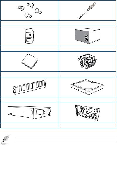
Installation tools and components
1 Bag of screws |
Phillips (cross) screwdriver |
PC chassis |
Power supply unit |
AMD AM4 CPU |
AMD AM4/AM3 compatible CPU Fan |
DDR4 DIMM |
SATA hard disk drive |
SATA optical disc drive (optional) |
Graphics card |
The tools and components in the table above are not included in the motherboard package.
xv

xvi

Product Introduction |
1 |
1.1Motherboard overview
1.1.1Before you proceed
Take note of the following precautions before you install motherboard components or change any motherboard settings.
•Unplug the power cord from the wall socket before touching any component.
•Before handling components, use a grounded wrist strap or touch a safely grounded object or a metal object, such as the power supply case, to avoid damaging them due to static electricity.
•Hold components by the edges to avoid touching the ICs on them.
•Whenever you uninstall any component, place it on a grounded antistatic pad or in the bag that came with the component.
•Before you install or remove any component, ensure that the ATX power supply is switched off or the power cord is detached from the power supply. Failure to do so may cause severe damage to the motherboard, peripherals, or components.
Chapter 1
ROG CROSSHAIR VI EXTREME |
1-1 |

1.1.2Motherboard layout
1 Chapter
Refer to 1.1.9 Internal connectors and 2.3.1 Rear I/O connection for more information about rear panel connectors and internal connectors.
1-2 |
Chapter 1: Product Introduction |

Layout contents
Connectors/Jumpers/Buttons and switches/Slots
1. ATX power connectors (24-pin EATXPWR; 8-pin EATX12V_1; 4-pin EATX12V_2; 4-pin EZ_PLUG)
2. AM4 CPU socket
3. DDR4 DIMM slots
4. AURA RGB headers (4-pin RGB_HEADER1-2)
5. ROG Monoblock connector (9 pin WB_SENSOR)
6.CPU, CPU optional, water pump+, extension, radiator, and chassis fan
|
connectors (4-pin CPU_FAN; 4-pin CPU_OPT; 4-pin W_PUMP+; 5-pin EXT_ |
1-23 |
|
FAN; 4-pin RAD1A-D_FAN; 4-pin RAD2A-D_FAN;4-pin CHA_FAN) |
|
7. |
ProbeIt |
1-32 |
8. |
RESET button (RESET) |
1-9 |
9. |
Power-on button (START) |
1-9 |
10. |
Q-Code LED |
1-13 |
11. |
LN2 Mode jumper (3-pin LN2_MODE) |
1-19 |
12. |
Slow Mode Switch (SLOW_MODE) |
1-11 |
13. |
RSVD switch (RSVD) |
1-11 |
14. |
ReTry button (RETRY_BUTTON) |
1-10 |
15. |
Safe Boot button (SAFE_BOOT) |
1-10 |
16. |
USB 3.1 Gen 2 front panel connector (U31G2_1) |
1-21 |
17. |
M.2 sockets (M.2_1(Socket 3); M.2_2(Socket 3)) |
1-30 |
18. |
USB 3.1 Gen 1 connectors (20-1 pin U31G1_78; U31G1_910) |
1-21 |
19. |
AMD® Serial ATA 6.0 Gb/s connectors (7-pin SATA6G_1-8) |
1-20 |
20. |
Water in, water out, and water flow connectors (2-pin W_IN; 2-pin W_OUT; |
1-31 |
|
3-pin W_FLOW) |
|
|
|
|
21. |
System panel connectors (10-1 pin F_PANEL; 4-pin SPEAKER) |
1-26 |
22. |
USB 2.0 connector (10-1 pin USB15) |
1-22 |
23. |
ROG extension connector (18-1 pin ROG_EXT) |
1-27 |
24. |
Thermal sensor connector (2-pin T_SENSOR) |
1-27 |
25. |
TPM connector (14-1 pin TPM) |
1-31 |
26. |
Addressable RGB header (4-1 pin ADD_HEADER) |
1-29 |
27. |
Front panel audio connector (10-1 pin AAFP) |
1-24 |
28. |
LED connector (5-pin LED2_SCON1) |
1-30 |
Chapter 1
ROG CROSSHAIR VI EXTREME |
1-3 |
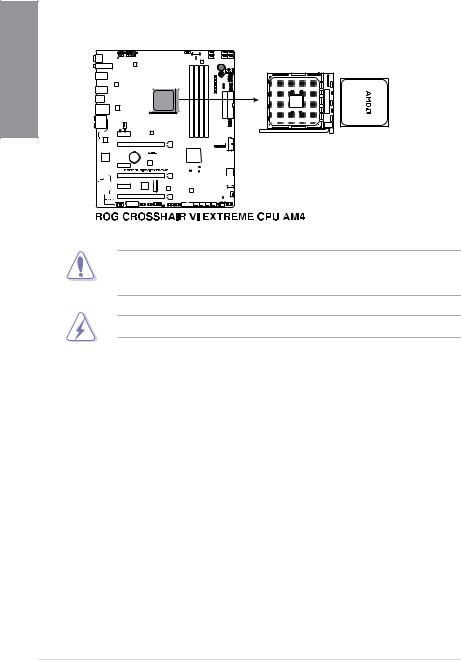
1.1.3Central Processing Unit (CPU)
The motherboard comes with an AM4 socket designed for AMD® Ryzen™ / 7th Generation A-series / Athlon™ Series CPU up to 8-core.
1 Chapter
The AM4 socket has a different pinout design. Ensure that you use a CPU designed for the AM4 socket. The CPU fits in only one correct orientation. DO NOT force the CPU into the socket to prevent bending the connectors on the socket and damaging the CPU!
Ensure that all power cables are unplugged before installing the CPU.
1-4 |
Chapter 1: Product Introduction |
1.1.4System memory
The motherboard comes with four Double Data Rate 4 (DDR4) Dual Inline Memory Modules (DIMM) slots.
A DDR4 module is notched differently from a DDR, DDR2, or DDR3 module. DO NOT install a DDR, DDR2, or DDR3 memory module to the DDR4 slot.
Recommended memory configurations
Chapter 1
ROG CROSSHAIR VI EXTREME |
1-5 |

1 Chapter
Memory configurations
You may install 2 GB, 4 GB, 8 GB, and 16 GB unbuffered and non ECC DDR4 DIMMs into the DIMM sockets.
• You may install varying memory sizes in Channel A and Channel B. The system maps the total size of the lower-sized channel for the dual-channel configuration. Any excess memory from the higher-sized channel is then mapped for single-channel operation.
•This motherboard does not support DIMMs made up of 512 Mb (64 MB) chips or less (Memory chip capacity counts in Megabit, 8 Megabit/Mb = 1 Megabyte/MB).
• The default memory operation frequency is dependent on its Serial Presence Detect (SPD), which is the standard way of accessing information from a memory module. Under the default state, some memory modules for overclocking may operate at a lower frequency than the vendor-marked value.
•For system stability, use a more efficient memory cooling system to support a full memory load (4 DIMMs) or overclocking condition.
•Always install the DIMMS with the same CAS Latency. For an optimum compatibility, we recommend that you install memory modules of the same version or data code (D/C) from the same vendor. Check with the vendor to get the correct memory modules.
1-6 |
Chapter 1: Product Introduction |
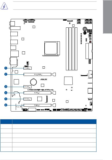
1.1.5Expansion slots
Unplug the power cord before adding or removing expansion cards. Failure to do so may cause you physical injury and damage motherboard components.
Slot No. Slot Description
1PCIe 2.0 x1_1 slot
2PCIe 3.0 x16/x8_1 slot
3PCIe 2.0 x1_2 slot
4 PCIe 3.0 x8_2 slot
5PCIe 2.0 x1_3 slot
6PCIe 2.0 x4_3 slot
Chapter 1
ROG CROSSHAIR VI EXTREME |
1-7 |
1 Chapter
AMD Ryzen™ Processors
VGA Configuration |
PCIe operating mode |
||
|
|
||
PCIe_x16/x8_1 |
PCIe_x8_2 |
||
|
|||
|
|
|
|
Single VGA/PCIe card |
x16 |
N/A |
|
|
|
|
|
Dual VGA/PCIe card |
x8 |
x8 |
|
|
|
|
|
AMD 7th Generation A-series / Athlon™ Processors
VGA Configuration |
|
PCIe operating mode |
|
|
PCIe_x16/x8_1 |
PCIe_x8_2 |
|
PCIe_x4_3 |
|
|
|
|||
|
|
|
|
|
Single VGA/PCIe card |
x8 |
N/A |
|
N/A |
|
|
|
|
|
Dual VGA/PCIe card |
x8 |
N/A |
|
x4 |
|
(PCI Express 2.0) |
|||
|
|
|
|
|
•We recommend that you provide sufficient power when running CrossFireX™ or SLI® mode.
•Connect chassis fans to the motherboard chassis fan connectors when using multiple graphics cards for better thermal environment.
1-8 |
Chapter 1: Product Introduction |
1.1.6Onboard buttons and switches
Onboard buttons and switches allow you to fine-tune performance when working on a bare or open-case system. This is ideal for overclockers and gamers who continually change settings to enhance system performance.
|
|
|
|
|
|
|
|
|
|
|
|
|
|
|
|
|
|
|
|
|
|
|
|
|
|
|
|
|
|
|
|
|
|
|
|
|
|
|
|
|
|
|
|
|
1 |
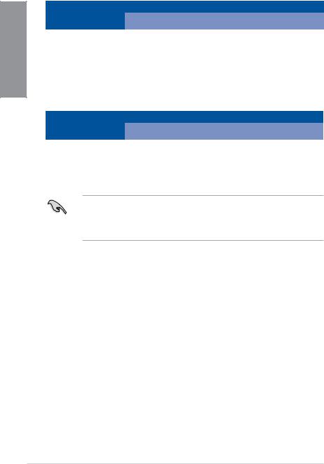
1. |
Power-on button (START) |
Chapter |
|||||||||||||||||||||||||||||||||||||||||||
|
|||||||||||||||||||||||||||||||||||||||||||||
|
The motherboard comes with a power-on button that allows you to power up or wake |
|
|||||||||||||||||||||||||||||||||||||||||||
|
up the system. The button also lights up when the system is plugged to a power source |
|
|||||||||||||||||||||||||||||||||||||||||||
|
indicating that you should shut down the system and unplug the power cable before |
|
|||||||||||||||||||||||||||||||||||||||||||
|
removing or installing any motherboard component. |
|
|||||||||||||||||||||||||||||||||||||||||||
|
|
|
|
|
|
|
|
|
|
|
|
|
|
|
|
|
|
|
|
|
|
|
|
|
|
|
|
|
|
|
|
|
|
|
|
|
|
|
|
|
|
|
|
|
|
|
|
|
|
|
|
|
|
|
|
|
|
|
|
|
|
|
|
|
|
|
|
|
|
|
|
|
|
|
|
|
|
|
|
|
|
|
|
|
|
|
|
|
|
|
|
|
|
|
|
|
|
|
|
|
|
|
|
|
|
|
|
|
|
|
|
|
|
|
|
|
|
|
|
|
|
|
|
|
|
|
|
|
|
|
|
|
|
|
|
|
|
|
|
|
|
|
|
|
|
|
|
|
|
|
|
|
|
|
|
|
|
|
|
|
|
|
|
|
|
|
|
|
|
|
|
|
|
|
|
|
|
|
|
|
|
|
|
|
|
|
|
|
|
|
|
|
|
|
|
|
|
|
|
|
|
|
|
|
|
|
|
|
|
|
|
|
|
|
|
|
|
|
|
|
|
|
|
|
|
|
|
|
|
|
|
|
|
|
|
|
|
|
|
|
|
|
|
|
|
|
|
|
|
|
|
|
|
|
|
|
|
|
|
|
|
|
|
|
|
|
|
|
|
|
|
|
|
|
|
|
|
|
|
|
|
|
|
|
|
|
|
|
|
|
|
|
|
|
|
|
|
|
|
|
|
|
|
|
|
|
|
|
|
|
|
|
|
|
|
|
|
|
|
|
|
|
|
|
|
|
|
|
|
|
|
|
|
|
|
|
|
|
|
|
|
|
|
|
|
|
|
|
|
|
|
|
|
|
|
|
|
|
|
|
|
|
|
|
|
|
|
|
|
|
|
|
|
|
|
|
|
|
|
|
|
|
|
|
|
|
|
|
|
|
|
|
|
|
|
|
|
|
|
|
|
|
|
|
|
|
|
|
|
|
|
|
|
|
|
|
|
|
|
|
|
|
|
|
|
|
|
|
|
|
|
|
|
|
|
|
|
|
|
|
|
|
|
|
|
|
|
|
|
|
|
|
|
|
|
|
|
|
|
|
|
|
|
|
|
|
|
|
|
|
|
|
|
|
|
|
|
|
|
|
|
|
|
|
|
|
|
|
|
|
|
|
|
|
|
|
|
|
|
|
|
|
|
|
|
|
|
|
|
|
|
|
|
|
|
|
|
|
|
|
|
|
|
|
|
|
|
|
|
|
|
|
|
|
|
|
|
|
|
|
|
|
|
|
|
|
|
|
|
|
|
|
|
|
|
|
|
|
|
|
|
|
|
|
|
|
|
|
|
|
|
|
|
|
|
|
|
|
|
|
|
|
|
|
|
|
|
|
|
|
|
|
|
|
|
|
|
|
|
|
|
|
|
|
|
|
|
|
|
|
|
|
|
|
|
|
|
|
|
|
|
|
|
|
|
|
|
|
|
|
|
|
|
|
|
|
|
|
|
|
|
|
|
|
|
|
|
|
|
|
|
|
|
|
|
|
|
|
|
|
|
|
|
|
|
|
|
|
|
|
|
|
|
|
|
|
|
|
|
|
|
|
|
|
|
|
|
|
|
|
|
|
|
|
|
|
|
|
|
|
|
|
|
|
|
|
|
|
|
|
|
|
|
|
|
|
|
|
|
|
|
|
|
|
|
|
|
|
|
|
|
|
|
|
|
|
|
|
|
|
|
|
|
|
|
|
|
|
|
|
|
|
|
|
|
|
|
|
|
|
|
|
|
|
|
|
|
|
|
|
|
|
|
|
|
|
|
|
|
|
|
|
|
|
|
|
|
|
|
|
|
|
|
|
|
|
|
|
|
|
|
|
|
|
|
|
|
|
|
|
|
|
|
|
|
|
|
|
|
|
|
|
|
|
|
|
|
|
|
|
|
|
|
|
|
|
|
|
|
|
|
|
|
|
|
|
|
|
|
|
|
|
|
|
|
|
|
|
|
|
|
|
|
|
|
|
|
|
|
|
|
|
|
|
|
|
|
|
|
|
|
|
|
|
|
|
|
|
|
|
|
|
|
|
|
|
|
|
|
|
|
|
|
|
|
|
|
|
|
|
|
|
|
|
|
|
|
|
|
|
|
|
|
|
|
|
|
|
|
|
|
|
|
|
|
|
|
|
|
|
|
|
|
|
|
|
|
|
|
|
|
|
|
|
|
|
|
|
|
|
|
|
|
|
|
|
|
|
|
|
|
|
|
|
|
|
|
|
|
|
|
|
|
|
|
|
|
|
|
|
|
|
|
|
|
|
|
|
|
|
|
|
|
|
|
|
|
|
|
|
|
|
|
|
|
|
|
|
|
|
|
|
|
|
|
|
|
|
|
|
|
|
|
|
|
|
|
|
|
|
|
|
|
|
|
|
|
|
|
|
|
|
|
|
|
|
|
|
|
|
|
|
|
|
|
|
|
|
|
|
|
|
|
|
|
|
|
|
|
|
|
|
|
|
|
|
|
|
|
|
|
|
|
|
|
|
|
|
|
|
|
|
|
|
|
|
|
|
|
|
|
|
|
|
|
|
|
|
|
|
|
|
|
|
|
|
|
|
|
|
|
|
|
|
|
|
|
|
|
|
|
|
|
|
|
|
|
|
|
|
|
|
|
|
|
|
|
|
|
|
|
|
|
|
|
|
|
|
|
|
|
|
|
|
|
|
|
|
|
|
|
|
|
|
|
|
|
|
|
|
|
|
|
|
|
|
|
|
|
|
|
|
|
|
|
|
|
|
|
|
|
|
|
|
|
|
|
|
|
|
|
|
|
|
|
|
|
|
|
|
|
|
|
|
|
|
|
|
|
|
|
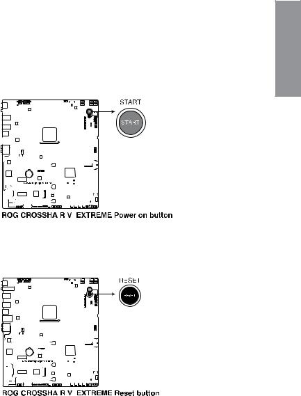
2.RESET button (RESET)
Press the reset button to reboot the system.
|
|
|
|
|
|
|
|
|
|
|
|
|
|
|
|
|
|
|
|
|
|
|
|
|
|
|
|
|
|
|
|
|
|
|
|
|
|
|
|
|
|
|
|
|
|
|
|
|
|
|
|
|
|
|
|
|
|
|
|
|
|
|
|
|
|
|
|
|
|
|
|
|
|
|
|
|
|
|
|
|
|
|
|
|
|
|
|
|
|
|
|
|
|
|
|
|
|
|
|
|
|
|
|
|
|
|
|
|
|
|
|
|
|
|
|
|
|
|
|
|
|
|
|
|
|
|
|
|
|
|
|
|
|
|
|
|
|
|
|
|
|
|
|
|
|
|
|
|
|
|
|
|
|
|
|
|
|
|
|
|
|
|
|
|
|
|
|
|
|
|
|
|
|
|
|
|
|
|
|
|
|
|
|
|
|
|
|
|
|
|
|
|
|
|
|
|
|
|
|
|
|
|
|
|
|
|
|
|
|
|
|
|
|
|
|
|
|
|
|
|
|
|
|
|
|
|
|
|
|
|
|
|
|
|
|
|
|
|
|
|
|
|
|
|
|
|
|
|
|
|
|
|
|
|
|
|
|
|
|
|
|
|
|
|
|
|
|
|
|
|
|
|
|
|
|
|
|
|
|
|
|
|
|
|
|
|
|
|
|
|
|
|
|
|
|
|
|
|
|
|
|
|
|
|
|
|
|
|
|
|
|
|
|
|
|
|
|
|
|
|
|
|
|
|
|
|
|
|
|
|
|
|
|
|
|
|
|
|
|
|
|
|
|
|
|
|
|
|
|
|
|
|
|
|
|
|
|
|
|
|
|
|
|
|
|
|
|
|
|
|
|
|
|
|
|
|
|
|
|
|
|
|
|
|
|
|
|
|
|
|
|
|
|
|
|
|
|
|
|
|
|
|
|
|
|
|
|
|
|
|
|
|
|
|
|
|
|
|
|
|
|
|
|
|
|
|
|
|
|
|
|
|
|
|
|
|
|
|
|
|
|
|
|
|
|
|
|
|
|
|
|
|
|
|
|
|
|
|
|
|
|
|
|
|
|
|
|
|
|
|
|
|
|
|
|
|
|
|
|
|
|
|
|
|
|
|
|
|
|
|
|
|
|
|
|
|
|
|
|
|
|
|
|
|
|
|
|
|
|
|
|
|
|
|
|
|
|
|
|
|
|
|
|
|
|
|
|
|
|
|
|
|
|
|
|
|
|
|
|
|
|
|
|
|
|
|
|
|
|
|
|
|
|
|
|
|
|
|
|
|
|
|
|
|
|
|
|
|
|
|
|
|
|
|
|
|
|
|
|
|
|
|
|
|
|
|
|
|
|
|
|
|
|
|
|
|
|
|
|
|
|
|
|
|
|
|
|
|
|
|
|
|
|
|
|
|
|
|
|
|
|
|
|
|
|
|
|
|
|
|
|
|
|
|
|
|
|
|
|
|
|
|
|
|
|
|
|
|
|
|
|
|
|
|
|
|
|
|
|
|
|
|
|
|
|
|
|
|
|
|
|
|
|
|
|
|
|
|
|
|
|
|
|
|
|
|
|
|
|
|
|
|
|
|
|
|
|
|
|
|
|
|
|
|
|
|
|
|
|
|
|
|
|
|
|
|
|
|
|
|
|
|
|
|
|
|
|
|
|
|
|
|
|
|
|
|
|
|
|
|
|
|
|
|
|
|
|
|
|
|
|
|
|
|
|
|
|
|
|
|
|
|
|
|
|
|
|
|
|
|
|
|
|
|
|
|
|
|
|
|
|
|
|
|
|
|
|
|
|
|
|
|
|
|
|
|
|
|
|
|
|
|
|
|
|
|
|
|
|
|
|
|
|
|
|
|
|
|
|
|
|
|
|
|
|
|
|
|
|
|
|
|
|
|
|
|
|
|
|
|
|
|
|
|
|
|
|
|
|
|
|
|
|
|
|
|
|
|
|
|
|
|
|
|
|
|
|
|
|
|
|
|
|
|
|
|
|
|
|
|
|
|
|
|
|
|
|
|
|
|
|
|
|
|
|
|
|
|
|
|
|
|
|
|
|
|
|
|
|
|
|
|
|
|
|
|
|
|
|
|
|
|
|
|
|
|
|
|
|
|
|
|
|
|
|
|
|
|
|
|
|
|
|
|
|
|
|
|
|
|
|
|
|
|
|
|
|
|
|
|
|
|
|
|
|
|
|
|
|
|
|
|
|
|
|
|
|
|
|
|
|
|
|
|
|
|
|
|
|
|
|
|
|
|
|
|
|
|
|
|
|
|
|
|
|
|
|
|
|
|
|
|
|
|
|
|
|
|
|
|
|
|
|
|
|
|
|
|
|
|
|
|
|
|
|
|
|
|
|
|
|
|
|
|
|
|
|
|
|
|
|
|
|
|
|
|
|
|
|
|
|
|
|
|
|
|
|
|
|
|
|
|
|
|
|
|
|
|
|
|
|
|
|
|
|
|
|
|
|
|
|
|
|
|
|
|
|
|
|
|
|
|
|
|
|
|
|
|
|
|
|
|
|
|
|
|
|
|
|
|
|
|
|
|
|
|
|
|
|
|
|
|
|
|
|
|
|
|
|
|
|
|
|
|
|
|
|
|
|
|
|
|
|
|
|
|
|
|
|
|
|
|
|
|
|
|
|
|
|
|
|
|
|
|
|
|
|
|
|
|
|
|
|
|
|
|
|
|
|
|
|
|
|
|
|
|
|
|
|
|
|
|
|
|
|
|
|
|
|
|
|
|
|
|
|
|
|
|
|
|
|
|
|
|
|
|
|
|
|
|
|
|
|
|
|
|
|
|
|
|
|
|
|
|
|
|
|
|
|
|
|
|
|
|
|
|
|
|
|
|
|
|
|
|
|
|
|
|
|
|
|
|
|
|
|
|
|
|
|
|
|
|
|
|
|
|
|
|
|
|
|
|
|
|
|
|
|
|
|
|
|
|
|
|
|
|
|
|
|
|
|
|
|
|
|
|
|
|
|
ROG CROSSHAIR VI EXTREME |
1-9 |
||||||||||||||||||||||||||||||||||||||||||
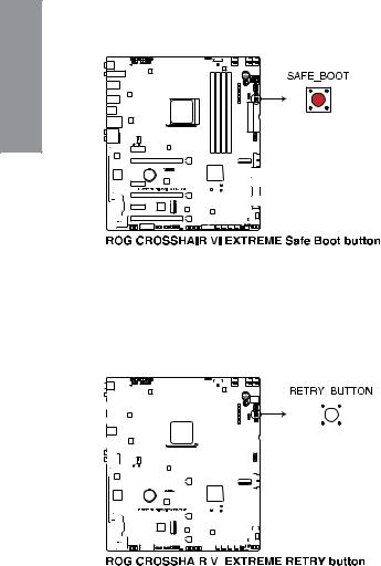
3. |
Safe Boot button (SAFE_BOOT) |
|
The Safe Boot button can be pressed anytime to force the system to reboot into the |
|
BIOS safe mode. This button temporarily applies safe settings to the BIOS while |
1 Chapter |
retaining any overclocked settings allowing you to modify the settings causing boot |
failure. Use this button when overclocking or tweaking the settings of your system. |
|
|
4.ReTry button (RETRY_BUTTON)
The ReTry button is specially designed for overclockers and is most useful during the booting process where the Reset button is rendered useless. When pressed, it forces the system to reboot while retaining the same settings to be retried in quick succession to achieve a successful POST.
|
|
|
|
|
|
|
|
|
|
|
|
|
|
|
|
|
|
|
|
|
|
|
|
|
|
|
|
|
|
|
|
|
|
|
|
|
|
|
|
|
|
|
|
|
|
|
|
|
|
|
|
|
|
|
|
|
|
|
|
|
|
|
|
|
|
|
|
|
|
|
|
|
|
|
|
|
|
|
|
|
|
|
|
|
|
|
|
|
|
|
|
|
|
|
|
|
|
|
|
|
|
|
|
|
|
|
|
|
|
|
|
|
|
|
|
|
|
|
|
|
|
|
|
|
|
|
|
|
|
|
|
|
|
|
|
|
|
|
|
|
|
|
|
|
|
|
|
|
|
|
|
|
|
|
|
|
|
|
|
|
|
|
|
|
|
|
|
|
|
|
|
|
|
|
|
|
|
|
|
|
|
|
|
|
|
|
|
|
|
|
|
|
|
|
|
|
|
|
|
|
|
|
|
|
|
|
|
|
|
|
|
|
|
|
|
|
|
|
|
|
|
|
|
|
|
|
|
|
|
|
|
|
|
|
|
|
|
|
|
|
|
|
|
|
|
|
|
|
|
|
|
|
|
|
|
|
|
|
|
|
|
|
|
|
|
|
|
|
|
|
|
|
|
|
|
|
|
|
|
|
|
|
|
|
|
|
|
|
|
|
|
|
|
|
|
|
|
|
|
|
|
|
|
|
|
|
|
|
|
|
|
|
|
|
|
|
|
|
|
|
|
|
|
|
|
|
|
|
|
|
|
|
|
|
|
|
|
|
|
|
|
|
|
|
|
|
|
|
|
|
|
|
|
|
|
|
|
|
|
|
|
|
|
|
|
|
|
|
|
|
|
|
|
|
|
|
|
|
|
|
|
|
|
|
|
|
|
|
|
|
|
|
|
|
|
|
|
|
|
|
|
|
|
|
|
|
|
|
|
|
|
|
|
|
|
|
|
|
|
|
|
|
|
|
|
|
|
|
|
|
|
|
|
|
|
|
|
|
|
|
|
|
|
|
|
|
|
|
|
|
|
|
|
|
|
|
|
|
|
|
|
|
|
|
|
|
|
|
|
|
|
|
|
|
|
|
|
|
|
|
|
|
|
|
|
|
|
|
|
|
|
|
|
|
|
|
|
|
|
|
|
|
|
|
|
|
|
|
|
|
|
|
|
|
|
|
|
|
|
|
|
|
|
|
|
|
|
|
|
|
|
|
|
|
|
|
|
|
|
|
|
|
|
|
|
|
|
|
|
|
|
|
|
|
|
|
|
|
|
|
|
|
|
|
|
|
|
|
|
|
|
|
|
|
|
|
|
|
|
|
|
|
|
|
|
|
|
|
|
|
|
|
|
|
|
|
|
|
|
|
|
|
|
|
|
|
|
|
|
|
|
|
|
|
|
|
|
|
|
|
|
|
|
|
|
|
|
|
|
|
|
|
|
|
|
|
|
|
|
|
|
|
|
|
|
|
|
|
|
|
|
|
|
|
|
|
|
|
|
|
|
|
|
|
|
|
|
|
|
|
|
|
|
|
|
|
|
|
|
|
|
|
|
|
|
|
|
|
|
|
|
|
|
|
|
|
|
|
|
|
|
|
|
|
|
|
|
|
|
|
|
|
|
|
|
|
|
|
|
|
|
|
|
|
|
|
|
|
|
|
|
|
|
|
|
|
|
|
|
|
|
|
|
|
|
|
|
|
|
|
|
|
|
|
|
|
|
|
|
|
|
|
|
|
|
|
|
|
|
|
|
|
|
|
|
|
|
|
|
|
|
|
|
|
|
|
|
|
|
|
|
|
|
|
|
|
|
|
|
|
|
|
|
|
|
|
|
|
|
|
|
|
|
|
|
|
|
|
|
|
|
|
|
|
|
|
|
|
|
|
|
|
|
|
|
|
|
|
|
|
|
|
|
|
|
|
|
|
|
|
|
|
|
|
|
|
|
|
|
|
|
|
|
|
|
|
|
|
|
|
|
|
|
|
|
|
|
|
|
|
|
|
|
|
|
|
|
|
|
|
|
|
|
|
|
|
|
|
|
|
|
|
|
|
|
|
|
|
|
|
|
|
|
|
|
|
|
|
|
|
|
|
|
|
|
|
|
|
|
|
|
|
|
|
|
|
|
|
|
|
|
|
|
|
|
|
|
|
|
|
|
|
|
|
|
|
|
|
|
|
|
|
|
|
|
|
|
|
|
|
|
|
|
|
|
|
|
|
|
|
|
|
|
|
|
|
|
|
|
|
|
|
|
|
|
|
|
|
|
|
|
|
|
|
|
|
|
|
|
|
|
|
|
|
|
|
|
|
|
|
|
|
|
|
|
|
|
|
|
|
|
|
|
|
|
|
|
|
|
|
|
|
|
|
|
|
|
|
|
|
|
|
|
|
|
|
|
|
|
|
|
|
|
|
|
|
|
|
|
|
|
|
|
|
|
|
|
|
|
|
|
|
|
|
|
|
|
|
|
|
|
|
|
|
|
|
|
|
|
|
|
|
|
|
|
|
|
|
|
|
|
|
|
|
|
|
|
|
|
|
|
|
|
|
|
|
|
|
|
|
|
|
|
|
|
|
|
|
|
|
|
|
|
|
|
|
|
|
|
|
|
|
|
|
|
|
|
|
|
|
|
|
|
|
|
|
|
|
|
1-10 |
|
|
|
|
|
|
|
|
|
|
|
|
|
|
|
|
|
|
|
|
|
|
|
|
|
|
|
|
|
|
|
|
|
|
|
|
|
|
|
|
|
|
|
Chapter 1: Product Introduction |
5. |
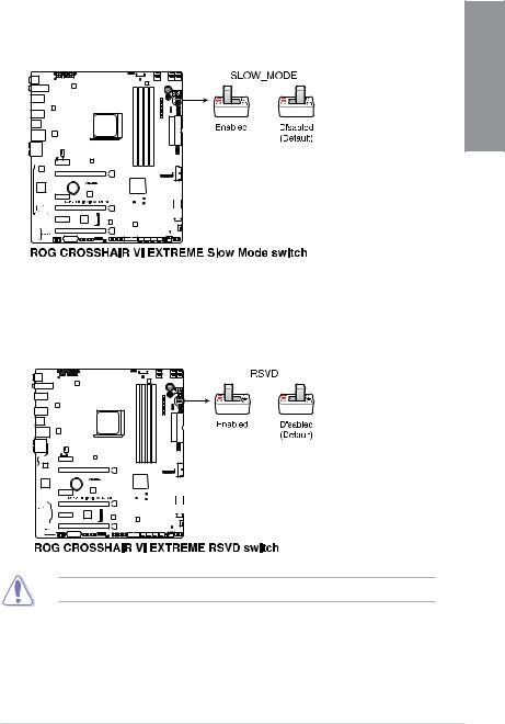
Slow Mode Switch (SLOW_MODE) |
|
|
Slow Mode Switch is employed during LN2 benching. The system may crash due to |
|
|
the CPU being unstable when using extreme overclocking, enabling slow mode will |
|
|
decrease the processor frequency and stabilize the system, allowing overclockers to |
1 |
|
keep track of their overclocking data. |
|
|
|
Chapter |
6.RSVD switch (RSVD)
This switch is reserved for ASUS-authorized technicians only.
Ensure to set this switch to disabled, enabling this switch may cause system failure.
ROG CROSSHAIR VI EXTREME |
1-11 |
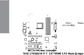
1.1.7Jumper
1. LN2 Mode jumper (3-pin LN2_MODE)
With LN2 mode activated, the ROG motherboard is optimized to remedy the cold-boot
bug during POST and help the system boot successfully. Chapter1 


|
|
|
|
|
|
1-12 |
|
Chapter 1: Product Introduction |
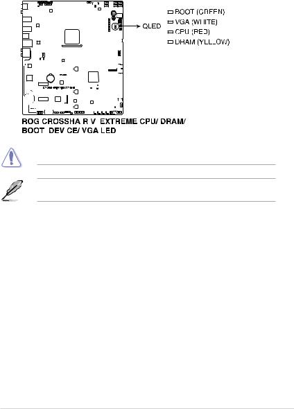
1.1.8Onboard LEDs
1. |
Q LEDs (BOOT, VGA, DRAM, CPU) |
|
||||||||||||||||||||||||||||||||||||||||||||
|
Q LEDs check key components (CPU, DRAM, VGA card, and booting devices) in |
|
||||||||||||||||||||||||||||||||||||||||||||
|
sequence during motherboard booting process. If an error is found, the corresponding |
1 |
||||||||||||||||||||||||||||||||||||||||||||
|
LED remains lit until the problem is solved. This user-friendly design provides an |
|||||||||||||||||||||||||||||||||||||||||||||
|
Chapter |
|||||||||||||||||||||||||||||||||||||||||||||
|
intuitive way to locate the root problem within seconds. |
|||||||||||||||||||||||||||||||||||||||||||||
|
|
|||||||||||||||||||||||||||||||||||||||||||||
|
|
|
|
|
|
|
|
|
|
|
|
|
|
|
|
|
|
|
|
|
|
|
|
|
|
|
|
|
|
|
|
|
|
|
|
|
|
|
|
|
|
|
|
|
|
|
|
|
|
|
|
|
|
|
|
|
|
|
|
|
|
|
|
|
|
|
|
|
|
|
|
|
|
|
|
|
|
|
|
|
|
|
|
|
|
|
|
|
|
|
|
|
|
|
|
|
|
|
|
|
|
|
|
|
|
|
|
|
|
|
|
|
|
|
|
|
|
|
|
|
|
|
|
|
|
|
|
|
|
|
|
|
|
|
|
|
|
|
|
|
|
|
|
|
|
|
|
|
|
|
|
|
|
|
|
|
|
|
|
|
|
|
|
|
|
|
|
|
|
|
|
|
|
|
|
|
|
|
|
|
|
|
|
|
|
|
|
|
|
|
|
|
|
|
|
|
|
|
|
|
|
|
|
|
|
|
|
|
|
|
|
|
|
|
|
|
|
|
|
|
|
|
|
|
|
|
|
|
|
|
|
|
|
|
|
|
|
|
|
|
|
|
|
|
|
|
|
|
|
|
|
|
|
|
|
|
|
|
|
|
|
|
|
|
|
|
|
|
|
|
|
|
|
|
|
|
|
|
|
|
|
|
|
|
|
|
|
|
|
|
|
|
|
|
|
|
|
|
|
|
|
|
|
|
|
|
|
|
|
|
|
|
|
|
|
|
|
|
|
|
|
|
|
|
|
|
|
|
|
|
|
|
|
|
|
|
|
|
|
|
|
|
|
|
|
|
|
|
|
|
|
|
|
|
|
|
|
|
|
|
|
|
|
|
|
|
|
|
|
|
|
|
|
|
|
|
|
|
|
|
|
|
|
|
|
|
|
|
|
|
|
|
|
|
|
|
|
|
|
|
|
|
|
|
|
|
|
|
|
|
|
|
|
|
|
|
|
|
|
|
|
|
|
|
|
|
|
|
|
|
|
|
|
|
|
|
|
|
|
|
|
|
|
|
|
|
|
|
|
|
|
|
|
|
|
|
|
|
|
|
|
|
|
|
|
|
|
|
|
|
|
|
|
|
|
|
|
|
|
|
|
|
|
|
|
|
|
|
|
|
|
|
|
|
|
|
|
|
|
|
|
|
|
|
|
|
|
|
|
|
|
|
|
|
|
|
|
|
|
|
|
|
|
|
|
|
|
|
|
|
|
|
|
|
|
|
|
|
|
|
|
|
|
|
|
|
|
|
|
|
|
|
|
|
|
|
|
|
|
|
|
|
|
|
|
|
|
|
|
|
|
|
|
|
|
|
|
|
|
|
|
|
|
|
|
|
|
|
|
|
|
|
|
|
|
|
|
|
|
|
|
|
|
|
|
|
|
|
|
|
|
|
|
|
|
|
|
|
|
|
|
|
|
|
|
|
|
|
|
|
|
|
|
|
|
|
|
|
|
|
|
|
|
|
|
|
|
|
|
|
|
|
|
|
|
|
|
|
|
|
|
|
|
|
|
|
|
|
|
|
|
|
|
|
|
|
|
|
|
|
|
|
|
|
|
|
|
|
|
|
|
|
|
|
|
|
|
|
|
|
|
|
|
|
|
|
|
|
|
|
|
|
|
|
|
|
|
|
|
|
|
|
|
|
|
|
|
|
|
|
|
|
|
|
|
|
|
|
|
|
|
|
|
|
|
|
|
|
|
|
|
|
|
|
|
|
|
|
|
|
|
|
|
|
|
|
|
|
|
|
|
|
|
|
|
|
|
|
|
|
|
|
|
|
|
|
|
|
|
|
|
|
|
|
|
|
|
|
|
|
|
|
|
|
|
|
|
|
|
|
|
|
|
|
|
|
|
|
|
|
|
|
|
|
|
|
|
|
|
|
|
|
|
|
|
|
|
|
|
|
|
|
|
|
|
|
|
|
|
|
|
|
|
|
|
|
|
|
|
|
|
|
|
|
|
|
|
|
|
|
|
|
|
|
|
|
|
|
|
|
|
|
|
|
|
|
|
|
|
|
|
|
|
|
|
|
|
|
|
|
|
|
|
|
|
|
|
|
|
|
|
|
|
|
|
|
|
|
|
|
|
|
|
|
|
|
|
|
|
|
|
|
|
|
|
|
|
|
|
|
|
|
|
|
|
|
|
|
|
|
|
|
|
|
|
|
|
|
|
|
|
|
|
|
|
|
|
|
|
|
|
|
|
|
|
|
|
|
|
|
|
|
|
|
|
|
|
|
|
|
|
|
|
|
|
|
|
|
|
|
|
|
|
|
|
|
|
|
|
|
|
|
|
|
|
|
|
|
|
|
|
|
|
|
|
|
|
|
|
|
|
|
|
|
|
|
|
|
|
|
|
|
|
|
|
|
|
|
|
|
|
|
|
|
|
|
|
|
|
|
|
|
|
|
|
|
|
|
|
|
|
|
|
|
|
|
|
|
|
|
|
|
|
|
|
|
|
|
|
|
|
|
|
|
|
|
|
|
|
|
|
|
|
|
|
|
|
|
|
|
|
|
|
|
|
|
|
|
|
|
|
|
|
|
|
|
|
|
|
|
|
|
|
|
|
|
|
|
|
|
|
|
|
|
|
|
|
|
|
|
|
|
|
|
|
|
|
|
|
|
|
|
|
|
|
|
|
|
|
|
|
|
|
|
|
|
|
|
|
|
|
|
|
|
|
|
|
|
|
|
|
|
|
|
|
|
|
|
|
|
|
|
|
|
|
|
|
|
|
|
|
|
|
|
|
|
|
|
|
|
|
|
|
|
|
|
|
|
|
|
|
|
|
|
|
|
|
|
|
|
|
|
|
|
|
|
|
|
|
|
|
|
|
|
|
|
|
|
|
|
|
|
|
|
|
|
|
|
|
|
|
|
|
|
|
|
|
|
|
|
|
|
|
|
|
|
|
|
|
|
|
|
|
|
|
|
|
|
|
|
|
|
|
|
|
|
|
|
|
|
|
|
|
|
|
|
|
|
|
|
|
|
|
|
|
|
|
|
|
|
|
|
|
|
|
|
|
|
|
|
|
|
|
|
|
|
|
|
|
|
|
|
|
|
|
|
|
|
|
|
|
|
|
|
|
|
|
|
|
|
|
|
|
|
|
|
|
|
|
|
|
|
|
|
|
|
|
|
|
|
|
|
|
|
|
|
|
|
|
|
|
|
|
|
|
|
|
|
|
|
|
|
|
|
|
|
|
|
|
|
|
|
|
|
|
|
|
|
|
|
|
|
|
|
|
|
|
|
|
|
|
|
|
|
|
|
|
|
|
|
|
|
|
|
|
|
The order which the LEDs light up may vary per CPU.
The Q LEDs provide the most probable cause of an error code as a starting point for troubleshooting. The actual cause may vary from case to case.
ROG CROSSHAIR VI EXTREME |
1-13 |
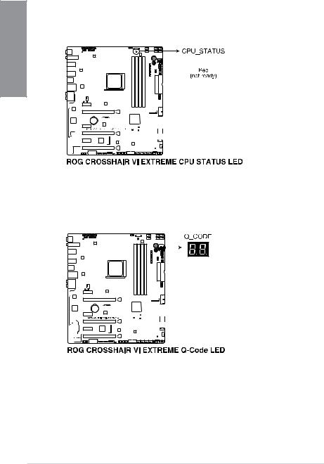
2.CPU status LED (CPU_STATUS)
This LED will indicate the current status of your CPU. A red light indicates that the CPU is not ready to boot, and the LED will turn off once the problem is solved. This userfriendly design helps you quickly identify whether your CPU is ready to boot or not.
1 Chapter
3.Q-Code LED
The Q-Code LED design provides you with a 2-digit error code that displays the system status. Refer to the Q-Code table on the following page for details.
The Q-Code LED provides the most probable cause of an error code as a starting point for troubleshooting. The actual cause may vary from case to case.
1-14 |
Chapter 1: Product Introduction |
 Loading...