

Page 1

R
MEW-AM
Socket 370 Intel® 810
microATX Motherboard
USER’S MANUAL
Page 2

USER'S NOTICE
No part of this manual, including the products and software described in it, may be reproduced, transmitted, transcribed, stored in a retrieval system, or translated into any language in
any form or by any means, except documentation kept by the purchaser for backup purposes,
without the express written permission of ASUSTeK COMPUTER INC. (“ASUS”).
ASUS PROVIDES THIS MANUAL “AS IS” WITHOUT WARRANTY OF ANY KIND,
EITHER EXPRESS OR IMPLIED, INCLUDING BUT NOT LIMITED T O THE IMPLIED
WARRANTIES OR CONDITIONS OF MERCHANTABILITY OR FITNESS FOR A PARTICULAR PURPOSE. IN NO EVENT SHALL ASUS, ITS DIRECTORS, OFFICERS,
EMPLOYEES OR AGENTS BE LIABLE FOR ANY INDIRECT, SPECIAL, INCIDENTAL, OR CONSEQUENTIAL DAMAGES (INCLUDING DAMAGES FOR LOSS OF
PROFITS, LOSS OF BUSINESS, LOSS OF USE OR DATA, INTERRUPTION OF BUSINESS AND THE LIKE), EVEN IF ASUS HAS BEEN ADVISED OF THE POSSIBILITY
OF SUCH DAMAGES ARISING FROM ANY DEFECT OR ERROR IN THIS MANUAL
OR PRODUCT.
Product warranty or service will not be extended if: (1) the product is repaired, modified or
altered, unless such repair, modification of alteration is authorized in writing by ASUS; or (2)
the serial number of the product is defaced or missing.
Products and corporate names appearing in this manual may or may not be registered trademarks or copyrights of their respective companies, and are used only for identification or
explanation and to the owners’ benefit, without intent to infringe.
• QuickStart and JumperFree are trademarks of ASUSTeK Computer Inc.
• Intel, LANDesk, and Pentium are registered trademarks of Intel Corporation.
• IBM and OS/2 are registered trademarks of International Business Machines.
• Symbios is a registered trademark of Symbios Logic Corporation.
• Windows and MS-DOS are registered trademarks of Microsoft Corporation.
• Adobe and Acrobat are registered trademarks of Adobe Systems Incorporated.
The product name and revision number are both printed on the product itself. Manual revi-
sions are released for each product design represented by the digit before and after the period
of the manual revision number. Manual updates are represented by the third digit in the manual
revision number.
For previous or updated manuals, BIOS, drivers, or product release information, contact ASUS
at http://www.asus.com.tw or through any of the means indicated on the following page.
SPECIFICATIONS AND INFORMATION CONTAINED IN THIS MANUAL ARE FURNISHED FOR INFORMATIONAL USE ONLY, AND ARE SUBJECT TO CHANGE AT
ANY TIME WITHOUT NOTICE, AND SHOULD NOT BE CONSTRUED AS A COMMITMENT BY ASUS. ASUS ASSUMES NO RESPONSIBILITY OR LIABILITY FOR
ANY ERRORS OR INACCURACIES THAT MA Y APPEAR IN THIS MANUAL, INCLUDING THE PRODUCTS AND SOFTWARE DESCRIBED IN IT.
Copyright © 1999 ASUSTeK COMPUTER INC. All Rights Reserved.
Product Name: ASUS MEW-AM
Manual Revision: 1.02 E439
Release Date: October 1999
2 ASUS MEW-AM User’s Manual
Page 3

ASUS CONTACT INFORMATION
ASUSTeK COMPUTER INC. (Asia-Pacific)
Marketing
Address: 150 Li-Te Road, Peitou, Taipei, Taiwan 112
Telephone: +886-2-2894-3447
Fax: +886-2-2894-3449
Email: info@asus.com.tw
Technical Support
MB/Other (tel): English: +886-2-2890-7121
Notebook (tel): English: +886-2-2890-7122
Server (tel): English: +886-2-2890-7123
Fax: +886-2-2895-9254
Email: tsd@asus.com.tw
Newsgroup: news2.asus.com.tw
WWW: www.asus.com.tw
FTP: ftp.asus.com.tw/pub/ASUS
ASUS COMPUTER INTERNATIONAL (America)
Marketing
Address: 6737 Mowry Avenue, Mowry Business Center, Building 2
Newark, CA 94560, USA
Fax: +1-510-608-4555
Email: info-usa@asus.com.tw
Technical Support
Fax: +1-510-608-4555
BBS: +1-510-739-3774
Email: tsd@asus.com
WWW: www.asus.com
FTP: ftp.asus.com/Pub/ASUS
ASUS COMPUTER GmbH (Europe)
Marketing
Address: Harkortstr. 25, 40880 Ratingen, BRD, Germany
Fax: +49-2102-4420-66
Email: sales@asuscom.de
Technical Support
Hotline: MB/Other: +49-2102-9599-0 Notebook: +49-2102-9599-10
Fax: +49-2102-9599-11
Online Support: www.asuscom.de/de/support
WWW: www.asuscom.de
FTP: ftp.asuscom.de/pub/ASUSCOM
ASUS MEW-AM User’s Manual 3
Page 4

CONTENTS
1. INTRODUCTION ............................................................................. 7
1.1 How This Manual Is Organized .................................................. 7
1.2 Item Checklist ............................................................................. 7
2. FEATURES ........................................................................................ 8
2.1 The ASUS MEW-AM Motherboard ........................................... 8
2.1.1 Specifications..................................................................... 8
2.1.2 Performance ....................................................................... 9
2.2 ASUS MEW-AM Part Definitions ........................................... 10
2.3 ASUS MEW-AM Part Locations.............................................. 11
3. HARDWARE SETUP ..................................................................... 12
3.1 Motherboard Layout ................................................................. 12
3.3 Hardware Setup Procedure ....................................................... 13
3.2 Layout Contents ........................................................................ 13
3.4 Motherboard Settings................................................................ 14
3.5 System Memory (DIMM) ......................................................... 15
3.5.1 General DIMM Notes ...................................................... 15
3.5.2 DIMM Installation ........................................................... 16
3.6 Central Processing Unit (CPU) ................................................. 17
3.7 Expansion Cards ....................................................................... 18
3.7.1 Expansion Card Installation Procedure............................ 18
3.8 External Connectors.................................................................. 19
3.9 Power Connection Procedures .................................................. 27
4. BIOS SETUP.................................................................................... 28
4.1 Managing and Updating Your BIOS ......................................... 28
4.1.1 Upon First Use of the Computer System ......................... 28
4.1.2 Updating BIOS Procedures (only when necessary)......... 29
4.2 BIOS Setup Program ................................................................ 31
4.2.1 BIOS Menu Bar ............................................................... 32
4.2.2 Legend Bar....................................................................... 32
4.3 Main Menu................................................................................ 34
4.3.1 Primary & Secondary Master/Slave ................................ 35
4.3.2 Keyboard Features ........................................................... 38
4.4 Advanced Menu ........................................................................ 40
4.4.1 I/O Device Configuration ................................................ 42
4.5 Security Menu ........................................................................... 43
4.6 Power Menu .............................................................................. 45
4.6.1 General Power Settings.................................................... 45
4.6.2 Power-Up Events ............................................................. 45
4.7 Boot Menu ................................................................................ 46
4.7.1 Boot Sequence ................................................................. 46
4.8 Exit Menu ................................................................................. 47
4 ASUS MEW-AM User’s Manual
Page 5

CONTENTS
5. SOFTWARE SETUP ........................................................................ 49
5.1 ASUS Smart Motherboard Support CD.................................... 49
5.1.2 Support CD Submenus..................................................... 50
5.2 Operating Systems .................................................................... 52
5.3 Starting Windows For the First Time........................................ 52
5.3.1 Intel 82802 Firmware Hub Device Found ....................... 53
5.4 ASUS LiveUpdate .................................................................... 54
5.3.2 PCI Multimedia Audio Device Found ............................. 55
5.5 Driver ........................................................................................ 56
5.5.1 VGA Driver Setup ........................................................... 56
5.6 Other ......................................................................................... 58
5.6.1 INF Update Utility for 810 Chipset ................................. 58
5.6.2 Intel Security Driver ........................................................ 59
5.6.3 YAMAHA S-YXG50....................................................... 60
5.6.4 YAMAHA XGStudio....................................................... 62
5.6.5 Microsoft DirectX 6.0 Driver .......................................... 63
5.6.6 PC-cillin 98 ...................................................................... 64
5.6.7 Adobe Acrobat Reader V4.0 ............................................ 65
5.7 Uninstalling Programs .............................................................. 66
6. SOFTWARE REFERENCE ............................................................ 67
6.1 Display Properties ..................................................................... 67
6.2 ASUS Update............................................................................ 71
6.3 Using Yamaha XGstudio Player ............................................... 73
6.3.1 Yamaha XGstudio Player Control Panel.......................... 73
6.4 Using Yamaha XGstudio Mixer ................................................ 74
6.4.1 Yamaha XGstudio Mixer Control Panel .......................... 74
6.5 Hardware Information............................................................... 76
7. APPENDIX........................................................................................ 77
7.1 PCI-L101 Fast Ethernet Card ................................................... 77
ASUS MEW-AM User’s Manual 5
Page 6

FCC & DOC COMPLIANCE
Federal Communications Commission Statement
This device complies with FCC Rules Part 15. Operation is subject to the following
two conditions:
• This device may not cause harmful interference, and
• This device must accept any interference received, including interference that
may cause undesired operation.
This equipment has been tested and found to comply with the limits for a Class B
digital device, pursuant to Part 15 of the FCC Rules. These limits are designed to
provide reasonable protection against harmful interference in a residential installation. This equipment generates, uses and can radiate radio frequency energy and, if
not installed and used in accordance with manufacturer's instructions, may cause
harmful interference to radio communications. However, there is no guarantee that
interference will not occur in a particular installation. If this equipment does cause
harmful interference to radio or television reception, which can be determined by
turning the equipment off and on, the user is encouraged to try to correct the interference by one or more of the following measures:
• Re-orient or relocate the receiving antenna.
• Increase the separation between the equipment and receiver.
• Connect the equipment to an outlet on a circuit different from that to which
the receiver is connected.
• Consult the dealer or an experienced radio/TV technician for help.
WARNING! Any changes or modifications to this product not expressly ap-
proved by the manufacturer could void any assurances of safety or performance
and could result in violation of Part 15 of the FCC Rules.
Canadian Department of Communications Statement
This digital apparatus does not exceed the Class B limits for radio noise emissions
from digital apparatus set out in the Radio Interference Regulations of the Canadian Department of Communications.
This Class B digital apparatus complies with Canadian ICES-003.
Cet appareil numérique de la classe B est conforme à la norme NMB-003 du Canada.
6 ASUS MEW-AM User’s Manual
Page 7

1. INTRODUCTION
1.1 How This Manual Is Organized
This manual is divided into the following sections:
1) INTRODUCTION Manual information and checklist
2) FEATURES Product information and specifications
3) HARDWARE SETUP Instructions on setting up the motherboard
4) BIOS SETUP Instructions on setting up the BIOS software
5) SOFTW ARE SETUP Instructions on setting up the included software
6) SOFTWARE REFERENCE Reference material for the included software
7) APPENDIX Optional items
1.2 Item Checklist
Check that your package is complete. If you discover damaged or missing items,
please contact your retailer.
(1) ASUS Motherboard
Sections/Checklist
1. INTRODUCTION
(1) Serial COM2 connector with bracket
(1) 80-conductor ribbon cable for internal UltraDMA/66 or UltraDMA/33 IDE
drives (NOTE: The 80-conductor cable has a 40-pin connector.)
(1) Ribbon cable for (1) 5.25” and (2) 3.5” floppy disk drives
(1) Bag of spare jumper caps
(1) Support CD with drivers and utilities
(1) This Motherboard User’s Manual
ASUS PCI-L101 Wake-On-LAN 10/100 fast ethernet card (optional)
ASUS MEW-AM User’s Manual 7
Page 8

2.1 The ASUS MEW-AM Motherboard
The MEW -AM motherboard from ASUS is designed for the new PC user who wants
simple features in a small package.
2.1.1 Specifications
• Latest Intel Socket 370 Processor Support! Supports Intel’s Celeron proces-
2. FEATURES
Specifications
• Latest Intel 810-DC100 Chipset! The 810-DC100 (GMCH+ICH) supports 66/
• Integrated Graphics! Controller supports 3D hyper pipelined architecture, par-
• ASUS Graphics Driver! You can gain about 12% performance over that of the
2. FEATURES
sor designed for Socket 370 and packaged in Plastic Pin Grid Array (PPGA).
100MHz FSB, UltraDMA/66, and 4MB 32-bit 100MHz SDRAM display cache
controller.
allel data processing and compression, precise pixel interpolation, full 2D hardware acceleration, and motion video acceleration. Optional onboard 4MB
SDRAM display cache allows up to 1024x768x16bit color for 3D graphics and
1600x1200x8bit color for 2D graphics.
standard graphics driver (2D highend graphics WinMark) using ASUS’ custom
graphics driver. ASUS custom graphics driver also provides more features and
provides selection of higher refresh rates and resolutions.
• V ersatile Memory Support! DRAM controller supports asymmetrical address-
ing and two DIMM sockets support Intel PC100-compliant SDRAMs (16, 32,
64, 128, or 256MB) up to 512MB. (supports a maximum of 4 sides)
• Latest Low Pin Count Multi-I/O: Provides two high-speed UAR T compatible
serial ports and one parallel port with EPP and ECP capabilities.
• Integrated IDE! Controller supports UltraDMA/66 up to 66MB/s, UltraDMA/
33 up to 33MB/s, and PIO Mode 4 up to 17MB/s.
• Desktop Management Interface (DMI) V2.3! Supports DMI through BIOS,
which allows hardware to communicate within a standard protocol creating a
higher level of compatibility. (Requires DMI-enabled components.)
• Peripheral Wake-Up! Supports Wake-On-LAN, Wake-On-Ring, and BIOS
Wake-Up.
• Firmware Hub! Provides security and other latest power computing features.
• Smart BIOS! 4Mb firmware gives a new easy-to-use interface which provides
more control and protection over the motherboard. Provides boot block write
protection and HD/SCSI/MO/ZIP/CD/Floppy boot selection. Hardware random
number generator supports new security software for data protection and secured Internet transactions.
• Enhanced ACPI & Anti-Boot Virus Protection! Programmable BIOS (Flash
EEPROM), offering enhanced ACPI for W indows 98 compatibility , built-in firmware-based virus protection, and autodetection of most devices for virtually automatic setup.
8 ASUS MEW-AM User’s Manual
Page 9

2. FEATURES
• Highest Audio Quality! AC’97 DAC/ADC (software audio) built into the au-
dio codec reduces noise to improve audio quality and performance for a SNR
(signal to noise ratio) of +90dB. These features greatly improve voice synthesis
and recognition. If more quality is required, an optional onboard Crystal PCI
audio improves audio quality beyond software audio.
2.1.2 Performance
• UltraPerformance! Onboard IDE Bus Master controller with two connectors
that support four IDE devices in two channels. Supports UltraDMA/66,
UltraDMA/33 (IDE DMA Mode 2), PIO Modes 3 & 4, and supports Enhanced
IDE devices, such as Tape Backup, CD-ROM, CD-R/RW, and LS-120 drives.
• Dual Speeds! CPU frequency can operate at either 66MHz or 100MHz while
system memory operates at either 100MHz or 66MHz. (100MHz CPU with 66MHz
SDRAM setting not supported) This asynchronous design can optimize the VGA
performance under shared memory configuration. Of course 100MHz/100MHz
synchronous host/DRAM clock is recommended for maximum performance.
Intelligence
2. FEATURES
• Double or Quadruple the IDE T ransfer Speed! IDE transfers using UltraDMA/
33 Bus Master IDE can handle rates up to 33MB/s and up to 66MB/s using
UltraDMA/66 technology. The best of all is that these new technology is compatible with existing ATA-2 IDE specifications so there is no need to upgrade
current IDE devices or cables.
• Concurrent PCI! Concurrent PCI allows multiple PCI transfers from PCI mas-
ter buses to memory to CPU.
• SDRAM Optimized Performance! ASUS smart series motherboards support
the new generation memory, Synchronous Dynamic Random Access Memory
(SDRAM), which increases the data transfer rate to 800MB/s max using PC100
SDRAM.
• ACPI Ready! ACPI (Advanced Configuration and Power Interface) is also imple-
mented on all ASUS smart series motherboards. ACPI provides more Energy
Saving Features for future operating systems (OS) supporting OS Direct Power
Management (OSPM) functionality . W ith these features implemented in the OS,
PCs can be ready around the clock, yet satisfy all the energy saving standards.
To fully utilize the benefits of ACPI, an ACPI-supported OS such as Windows
98 must be used.
• Extreme Graphics! The integrated motion compensation allows for smooth
MPEG1 or MPEG2 video playback. Fast 3D graphics engine allows for an exciting gameplay experience.
ASUS MEW-AM User’s Manual 9
Page 10

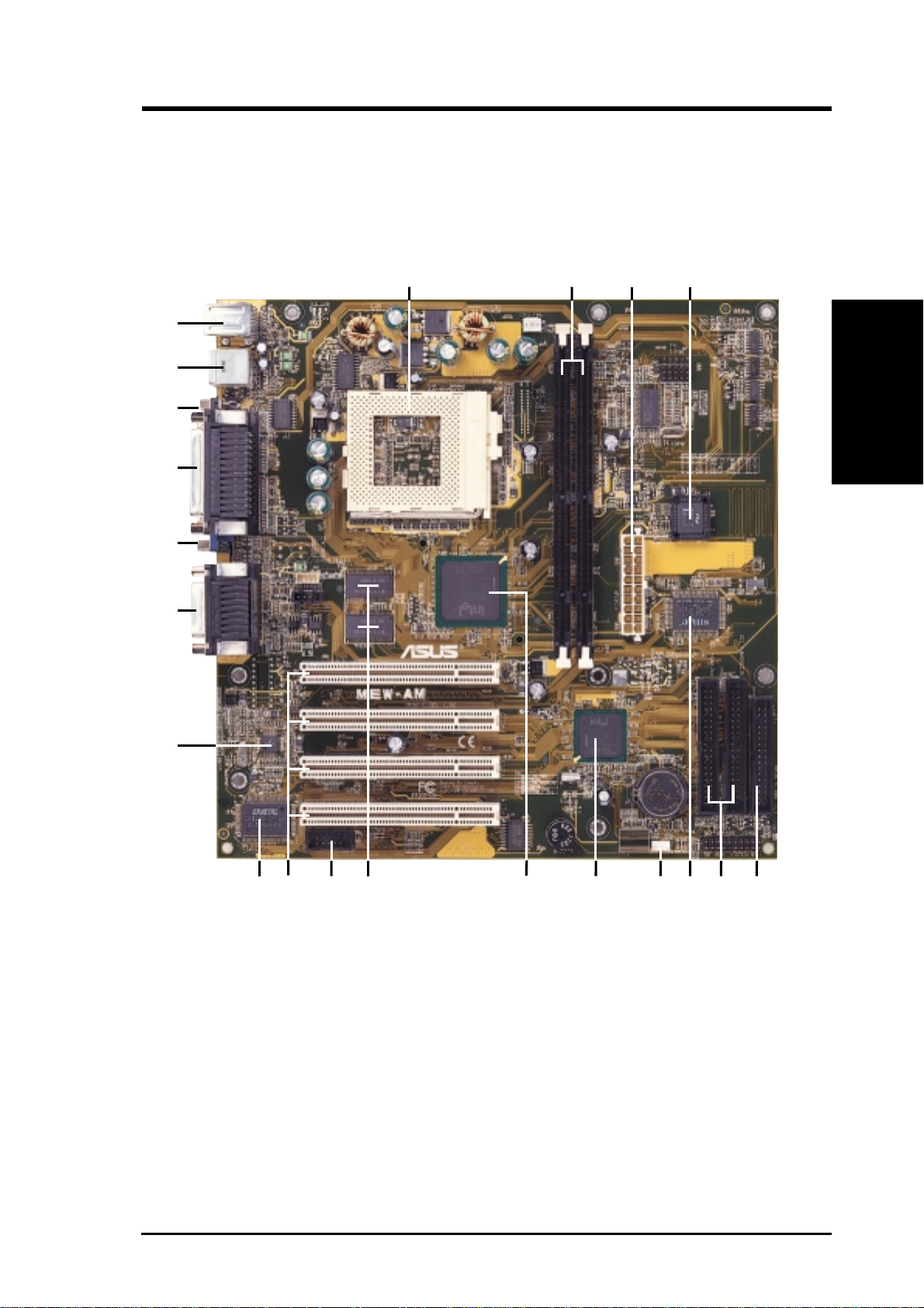
2.2 ASUS MEW-AM Part Definitions
The following are part descriptions for the motherboard parts shown on the next
page.
Part Definitions
2. FEATURES
10
11
12
13
14
15
16
17
18
19
20
21
2. FEATURES
Socket 370 for Intel Celeron 370 processors
1
DIMM Sockets
2
ATX Power Connector for connection to an ATX power supply
3
Four Mbit Firmware Hub (programmable BIOS)
4
Floppy Disk Drive Connector
5
Primary and Secondary IDE Connectors
6
Low Pin Count Multi-I/O Chipset
7
Wake-On-LAN Connector
8
Intel I/O Controller Hub (ICH)
9
Intel 810-DC100 (GMCH-DC100) Integrated Graphics Chipset
High-speed 4MB SDRAM for integrated AGP VGA
Serial COM2 Header
Four PCI Slots
Crystal Audio Chipset (optional)
AC’97 V2.1 Audio CODEC
Joystick, MIDI, Line Out, Line In, Microphone In Connectors (optional)
VGA Monitor Output Connector
Parallel Connector
Serial COM1 Connector
USB Connectors
PS/2 Mouse, PS/2 Keyboard Connectors
10 ASUS MEW-AM User’s Manual
Page 11
2. FEATURES
2.3 ASUS MEW-AM Part Locations
21
20
19
18
17
16
2
31
4
2. FEATURES
Part Locations
15
14
13
12
10
8
6
7911
5
ASUS MEW-AM User’s Manual 11
Page 12

3. HARDWARE SETUP
3.1 Motherboard Layout
PS2KBMS
T: Mouse
B: Keyboard
USB
T: Port 1
B: Port 2
COM1
Socket 370
CPU_FAN
FS4
FS3
FS2
FS1
External
Frequency
Selection
FS0
Motherboard Layout
3. H/W SETUP
PRINTER
PARALLEL PORT
VGA
Line
Out
Line
In
Mic
GAME_AUDIO
In
32-bit PCI
Audio
Chipset
Audio
Codec
CD_IN
2 MB
SDRAM
2 MB
SDRAM
PCI Slot 1
MEW-AM
PCI Slot 2
PCI Slot 3
PCI Slot 4
COM2
Intel 810
Graphics &
Memory
Controller
Hub (GMCH)
DIMM Socket 1 (64/72-bit, 168-pin module)
DIMM Socket 2 (64/72-bit, 168-pin module)
(ATXPWR)
Row
01
0
3
2
1
ATX Power Connector
Intel I/O
Controller
Hub (ICH)
CR2032 3V
Lithium Cell
CMOS Power
RTCLR
WOL_CON
4Mbit
Firmware
Hub
(FWH)
Super I/O
PRIMARY IDE
SECONDARY
PANEL
IDE
FLOPPY
(Grayed items are optional at the time of purchase.)
12 ASUS MEW-AM User’s Manual
Page 13

3. HARDWARE SETUP
3.2 Layout Contents
Motherboard Settings
1) FS0, FS1, FS2, FS3, FS4 p.14 CPU External Clock (BUS) Frequency Setting
Expansion Slots
1) DIMM1, DIMM2 p.15 168-Pin DIMM Memory Support
2) Socket 370 p.17 Central Processing Unit (CPU) Socket
3) PCI1, PCI2, PCI3, PCI4 p.18 32-bit PCI Bus Expansion Slots
Connectors
1) PS2KBMS p.19 PS/2 Mouse Connector (6-pin female)
2) PS2KBMS p.19 PS/2 Keyboard Connector (6-pin female)
3) USB p.20 Universal Serial Bus Ports 1 & 2 (Two 4-pin female)
4) PRINTER p.20 Parallel Port Connector (25-pin female)
5) COM1 p.20 Serial Port COM1 Connector (9-pin male)
6) VGA p.21 Monitor (VGA) Output Connector (15-pin female)
7) GAME_AUDIO p.21 Joystick/MIDI Connector (15-pin female) (optional)
8) GAME_AUDIO p.21 Audio Port Connectors (Three 1/8” female) (optional)
9) PRIMARY/SECONDAR Y IDE p.22 Primary/Secondary IDE Connectors (Two 40-1pins)
10) FLOPPY p.22 Floppy Disk Drive Connector (34-1pins)
11) WOL_CON p.23 Wake-On-LAN Connector (3 pins)
12) COM2 p.23 Serial Port COM2 Header (10-1 pins)
13) CPU_FAN, CHA_FAN p.24 CPU and Chassis Fan Connectors (3 pins)
14) LED (PANEL) p.25 System Message LED (2 pins)
15) KEYLOCK (PANEL) p.25 Keyboard Lock Switch Lead (2 pins)
16) EXSMI (PANEL) p.25 System Management Interrupt Switch Lead (2 pins)
17) SPEAKER (PANEL) p.25 System Warning Speaker Connector (4 pins)
18) PWRSW (PANEL) p.25 ATX Power / Soft-Off Switch Lead (2 pins)
19) HDLED (PANEL) p.25 IDE Activity LED (2 pins)
20) PLED (PANEL) p.25 System Power LED Lead (3-1 pins)
21) RESET (PANEL) p.25 Reset Switch Lead (2 pins)
22) CD_IN p.26 Internal Audio Connector (4-pins) (optional)
23) ATXPWR p.26 ATX Power Supply Connector (20 pins)
3. H/W SETUP
Layout Contents
3.3 Hardware Setup Procedure
Before using your computer, you must complete the following steps:
• Check Motherboard Settings
• Install Memory Modules
• Install the Central Processing Unit (CPU)
• Install Expansion Cards
• Connect Ribbon Cables, Panel Wires, and Power Supply
ASUS MEW-AM User’s Manual 13
Page 14

3.4 Motherboard Settings
WARNING! Computer motherboards and expansion cards contain very delicate
Integrated Circuit (IC) chips. To protect them against damage from static electricity, you should follow some precautions whenever you work on your computer.
1. Unplug your computer when working on the inside.
2. Use a grounded wrist strap before handling computer components. If you do
3. Hold components by the edges and try not to touch the IC chips, leads or con-
4. Place components on a grounded antistatic pad or on the bag that came with the
1) CPU External Frequency Setting (FS0, FS1, FS2, FS3, FS4)
System Memory
3. H/W SETUP
3. HARDWARE SETUP
not have one, touch both of your hands to a safely grounded object or to a metal
object, such as the power supply case.
nectors, or other components.
component whenever the components are separated from the system.
Current PCI bus is limited to 33MHz, Socket 370 Celeron processors limited to
66MHz, and SDRAM limited to the DIMM type 66/100/133MHz. (66MHz
SDRAM is not supported on this motherboard.) Other settings are for experienced users only.
Recommended
CPU Setting
NOTE: For updated processor settings, please visit ASUS’ web site (see ASUS
CONTACT INFORMATION)
WARNING! CPU frequencies above 66MHz exceed the specifications for cur-
rent Celeron processors and are not guaranteed to be stable. Premature wearing of
the processor may result when overclocking. Be sure that the DIMM you use can
handle the specified SDRAM MHz or else bootup will not be possible.
14 ASUS MEW-AM User’s Manual
Page 15
3. HARDWARE SETUP
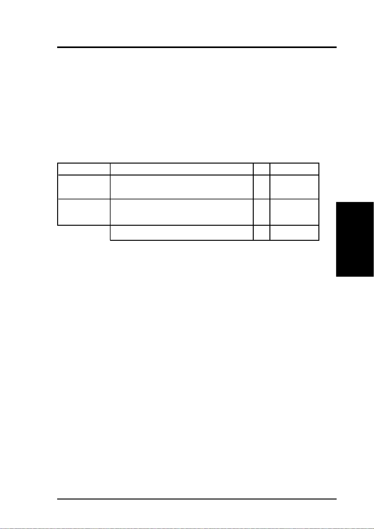
3.5 System Memory (DIMM)
NOTE: No hardware or BIOS setup is required after adding or removing memory.
This motherboard uses only Dual Inline Memory Modules (DIMMs). Sockets are
available for 3.3Volt (power level) unbuffered Synchronous Dynamic Random Ac-
cess Memory (SDRAM).
This chipset does not support ECC. However, ECC memory modules may still be
used, but the ECC function will not be available.
Install memory in any combination as follows:
Location 168-pin DIMM SDRAM Total Memory
DIMM1 Single-Sided/Double-Sided x1
(Rows 0&1) 16, 32, 64, 128MB, or 256MB
DIMM2 Single-Sided/Double-Sided x1
(Rows 2&3)
16, 32, 64, 128MB, or 256MB
Total System Memory (Max 512MB) =
NOTE: At the time this User’s Manual was written, 256MB DIMMs are only avail-
able as Double-Sided registered memory (128Mbit cells). Using 2x2x2 SDRAM can
greatly improve the onboard graphics’ performance.
3.5.1 General DIMM Notes
• This motherboard operates at 100MHz, therefore PC100-compliant modules must
be used because of the strict timing issues involved under this speed.
• ASUS motherboards support SPD (Serial Presence Detect) DIMMs. This is the
memory of choice for best performance vs. stability.
• SDRAM chips are generally thinner with higher pin density than EDO (Extended Data Output) chips.
• BIOS shows SDRAM memory on bootup screen.
• Single-sided DIMMs come in 16, 32, 64,128MB; double-sided come in 32, 64,
128, 256MB.
3. H/W SETUP
System Memory
ASUS MEW-AM User’s Manual 15
Page 16
3. HARDWARE SETUP
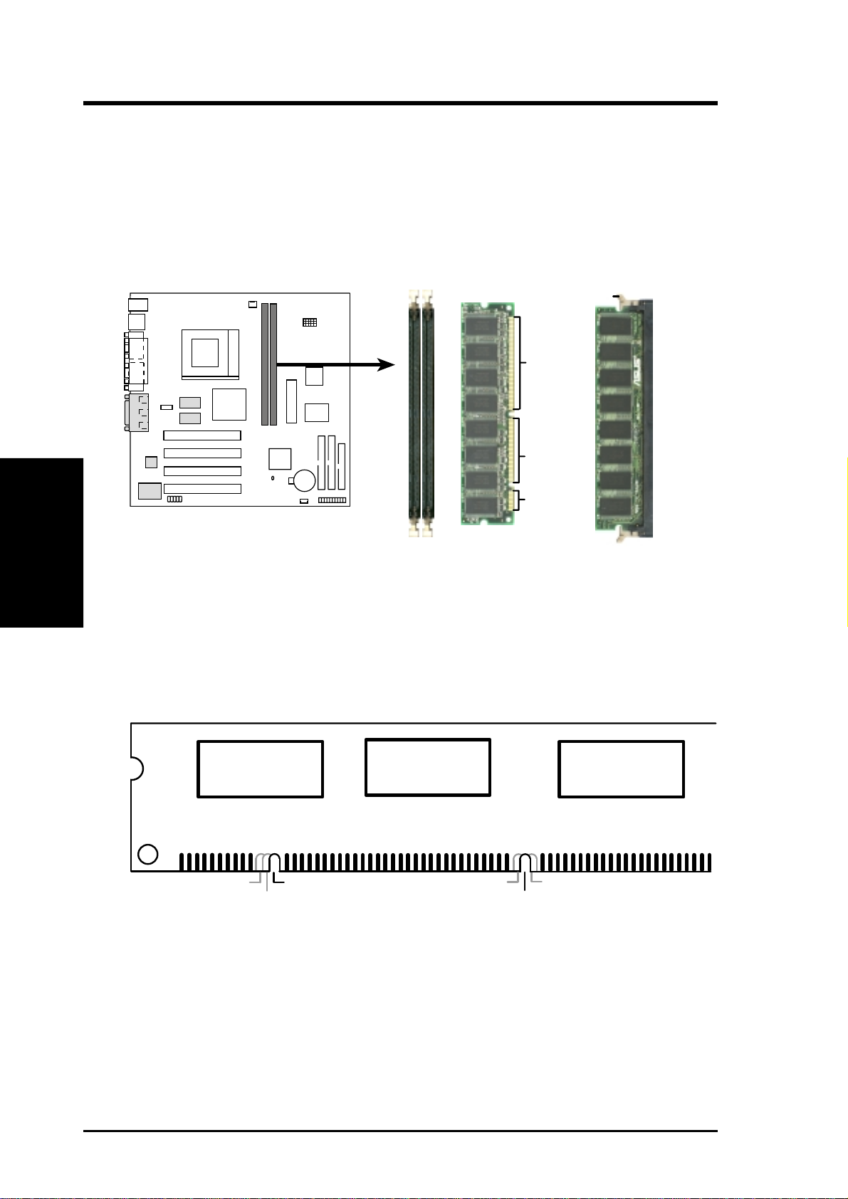
3.5.2 DIMM Installation
Insert the module(s) as shown. Because the number of pins are different on either
side of the breaks, the module will only fit in the orientation shown. DIMM modules are longer and have different pin contact on each side and therefore have a
higher pin density. SIMMs have the same pin contact on both sides.
Lock
88 Pins
3. H/W SETUP
CPU
1
MEW-AM
60 Pins
20 Pins
MEW-AM 168-Pin DIMM Sockets
FRONT
The DIMMs must be 3.3V Unbuffered for this motherboard. To determine the DIMM
type, check the notches on the DIMMs (see figure below).
168-Pin DIMM Notch Key Definitions (3.3V)
DRAM Key Position
RFU
Buffered
Unbuffered
Voltage Key Position
5.0V
Reserved
3.3V
The notches on the DIMM will shift between left, center, or right to identify the type
and also to prevent the wrong type from being inserted into the DIMM slot on the
motherboard. You must ask your retailer the correct DIMM type before purchasing.
This motherboard supports four clock signals per DIMM slot.
16 ASUS MEW-AM User’s Manual
Page 17
3. HARDWARE SETUP
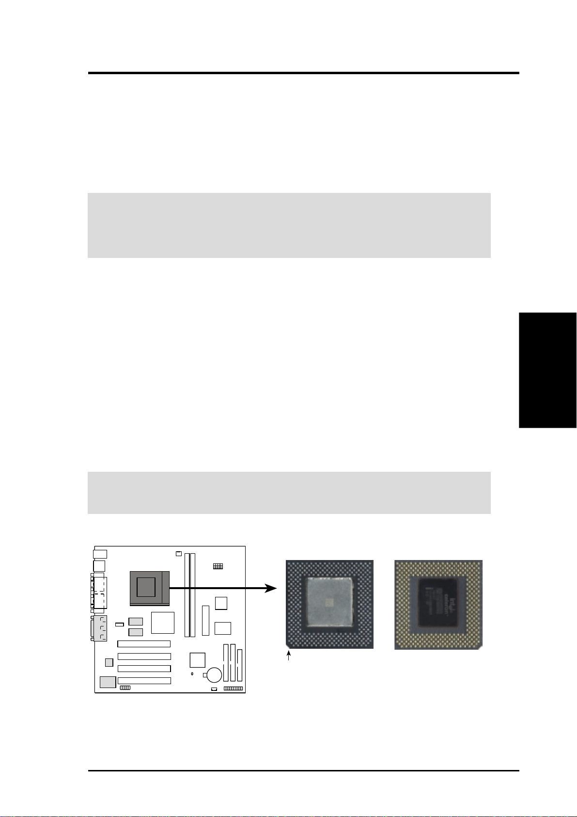
3.6 Central Processing Unit (CPU)
The motherboard provides a ZIF Socket 370. The CPU that came with the motherboard should have a fan attached to it to prevent overheating. If this is not the case,
then purchase a fan before you turn on your system.
WARNING! Be sure that there is sufficient air circulation across the processor’s
heatsink by regularly checking that your CPU fan is working. W ithout sufficient
circulation, the processor could overheat and damage both the processor and the
motherboard. You may install an auxiliary fan, if necessary.
To install a CPU, first turn off your system and remove its cover. Locate the ZIF
socket and open it by first pulling the lever sideways away from the socket then
upwards to a 90-degree angle. Insert the CPU with the correct orientation as shown.
The notched corner should point towards the end of the lever . Because the CPU has
a corner pin for two of the four corners, the CPU will only fit in the orientation as
shown. The picture is for reference only; you should have a CPU fan that covers the
face of the CPU. With the added weight of the CPU fan, no force is required to
insert the CPU. Once completely inserted, close the socket’s lever while holding
down the CPU.
NOTE: Do not forget to set the correct Bus Frequency and Multiple (frequency
multiple setting is available only on unlocked processors) for your Socket 370 processor or else boot-up may not be possible.
3. H/W SETUP
Expansion Cards
CAUTION! Be careful not to scrape the motherboard when mounting a clamp-
style processor fan or else damage may occur to the motherboard.
Socket 370 CPU (Top) Socket 370 CPU (Bottom)
1
MEW-AM
Notch
MEW-AM Socket 370
ASUS MEW-AM User’s Manual 17
Page 18

3. HARDWARE SETUP
3.7 Expansion Cards
WARNING! Make sure that you unplug your power supply when adding or
removing expansion cards or other system components. Failure to do so may
cause severe damage to both your motherboard and expansion cards.
3.7.1 Expansion Card Installation Procedure
1. Read the documentation for your expansion card and make any necessary hardware or software settings for your expansion card, such as jumpers or switches.
2. Remove your computer system’s cover and the bracket plate with screw on the
slot you intend to use. Keep the bracket for possible future use.
3. Carefully align the card’s connectors and press firmly.
4. Secure the card on the slot with the screw you removed above.
Expansion Cards
3. H/W SETUP
5. Replace the computer system’s cover.
6. Set up the BIOS if necessary.
7. Install the necessary software drivers for your expansion card.
18 ASUS MEW-AM User’s Manual
Page 19
3. HARDWARE SETUP
3.8 External Connectors
WARNING! Some pins are used for connectors or power sources. These are
clearly distinguished from jumpers in the Motherboard Layout. Placing jumper
caps over these connector pins will cause damage to your motherboard.
IMPORTANT: Ribbon cables should always be connected with the red stripe to
Pin 1 on the connectors. Pin 1 is usually on the side closest to the power connector on hard drives and CD-ROM drives, but may be on the opposite side on
floppy disk drives. Check the connectors before installation because there may
be exceptions. Look on IDE ribbon cable must be less than 46 cm (18 in.), with
the second drive connector no more than 15 cm (6 in.) from the first connector.
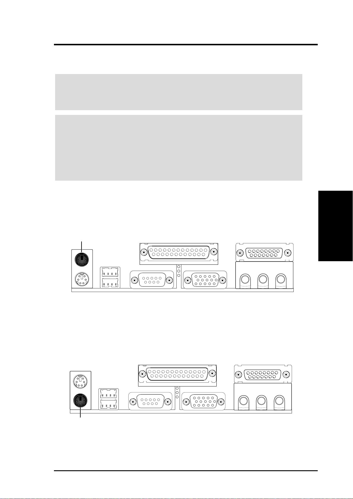
1) PS/2 Mouse Connector (6-pin PS2KBMS)
The system will direct IRQ12 to the PS/2 mouse if one is detected. If one is not
detected, expansion cards can use IRQ12.
PS/2 Mouse (6-pin Female)
2) PS/2 Keyboard Connector (6-pin PS2KBMS)
This connection is for a standard keyboard using an PS/2 plug (mini DIN). This
connector will not allow standard AT size (large DIN) keyboard plugs. You
may use a DIN to mini DIN adapter on standard AT keyboards.
Connectors
3. H/W SETUP
PS/2 Keyboard (6-pin Female)
ASUS MEW-AM User’s Manual 19
Page 20
3. H/W SETUP
Connectors
3. HARDWARE SETUP
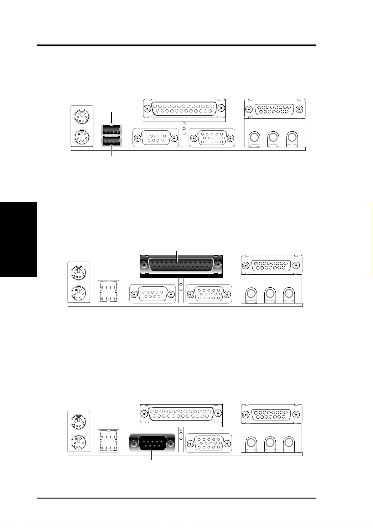
3) Universal Serial Bus Ports (Two 4-pin USB)
Two USB ports are available for connecting USB devices.
USB 1
Universal Serial Bus (USB) 2
4) Parallel Port Connector (25-pin PRINTER)
The parallel connector is used for a single parallel device such as a printer or a
portable drive. See Parallel Port in 4.4.1 I/O Device Configuration for settings.
NOTE: Serial printers must be connected to the serial port.
Parallel (Printer) Port (25-pin Female)
5) Serial Port Connector (9-pin COM1)
One serial port is ready for a mouse or other serial devices. A second serial port
is available using a serial port bracket connected from the motherboard to an
expansion slot opening. See Serial Port A or B in 4.4.1 I/O Device Configura-
tion for settings.
Serial Port (9-pin Male) COM 1
20 ASUS MEW-AM User’s Manual
Page 21
3. HARDWARE SETUP
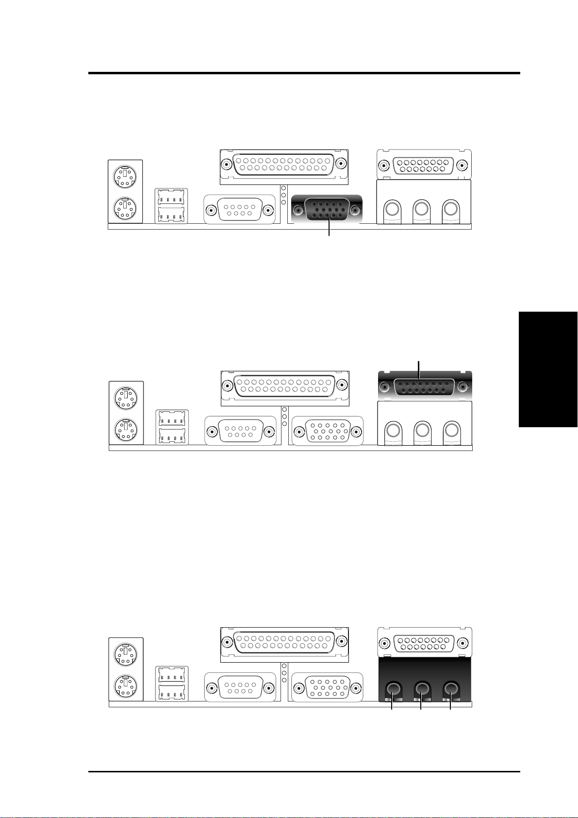
6) Monitor Output Connector (15-pin VGA)
This connector is for output to a VGA-compatible device.
VGA Monitor (15-pin Female)
7) Joystick/MIDI Connector (15-pin GAME_AUDIO) (optional)
You may connect game joysticks or game pads to this connector for playing
games. Connect MIDI devices for playing or editing professional audio.
Joystick/Midi (15-pin Female)
NOTE: The onboard game port is to be used only if you are not using any PCI
or ISA audio card with a game port.
8) Audio Port Connectors (Three 1/8” GAME_AUDIO) (optional)
Line Out (lime) can be connected to headphones or preferably powered speak-
ers. Line In (light blue) allows tape players or other audio sources to be recorded by your computer or played through the Line Out (lime). Mic (pink)
allows microphones to be connected for inputting voice.
Connectors
3. H/W SETUP
MicLine InLine Out
1/8" Stereo Audio Connectors
ASUS MEW-AM User’s Manual 21
Page 22
3. H/W SETUP
Connectors
3. HARDWARE SETUP
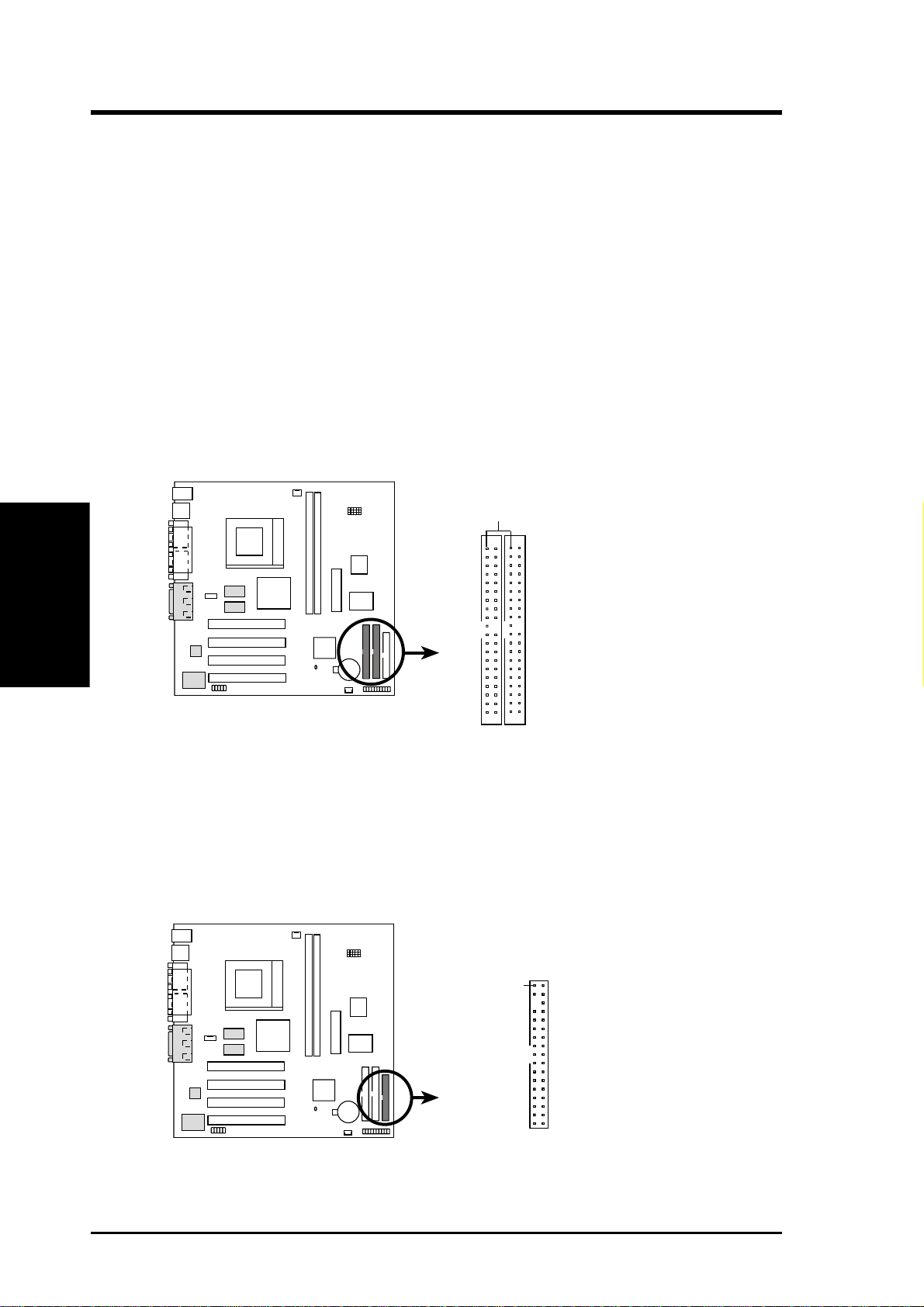
9) Primary / Secondary IDE Connectors (Two 40-1pin IDE)
These connectors support the provided IDE hard disk ribbon cable.
After connecting the single end to the board, connect the two plugs at the other
end to your hard disk(s). If you install two hard disks, you must configure the
second drive to Slave mode by setting its jumper accordingly. Please refer to
your hard disk documentation for the jumper settings. (Pin 20 is removed to
prevent inserting in the wrong orientation when using ribbon cables with
pin 20 plugged).
TIP: You may configure two hard disks to be both Masters with two ribbon
cables – one for the primary IDE connector and another for the secondary IDE
connector and select the boot disk through Boot Sequence in 4.7 Boot Menu.
IMPORTANT: UltraDMA/66 IDE devices must use an 80-wire IDE cable
or else devices will automatically be limited to UltraDMA/33 mode.
PIN 1
1
MEW-AM
Primary IDE Connector
MEW-AM IDE Connectors
NOTE: Orient the red markings
on the IDE ribbon cable to
Secondary IDE Connector
PIN 1
10) Floppy Disk Drive Connector (34-1pin FLOPPY)
This connector supports the provided floppy drive ribbon cable. After connecting the single end to the board, connect the two plugs on the other end to the
floppy drives. (Pin 5 is removed to prevent inserting in the wrong orienta-
tion when using ribbon cables with pin 5 plugged).
NOTE: Orient the red markings on
the floppy ribbon cable to
PIN 1
PIN 1
1
MEW-AM
MEW-AM Floppy Disk Drive Connector
22 ASUS MEW-AM User’s Manual
Page 23
3. HARDWARE SETUP
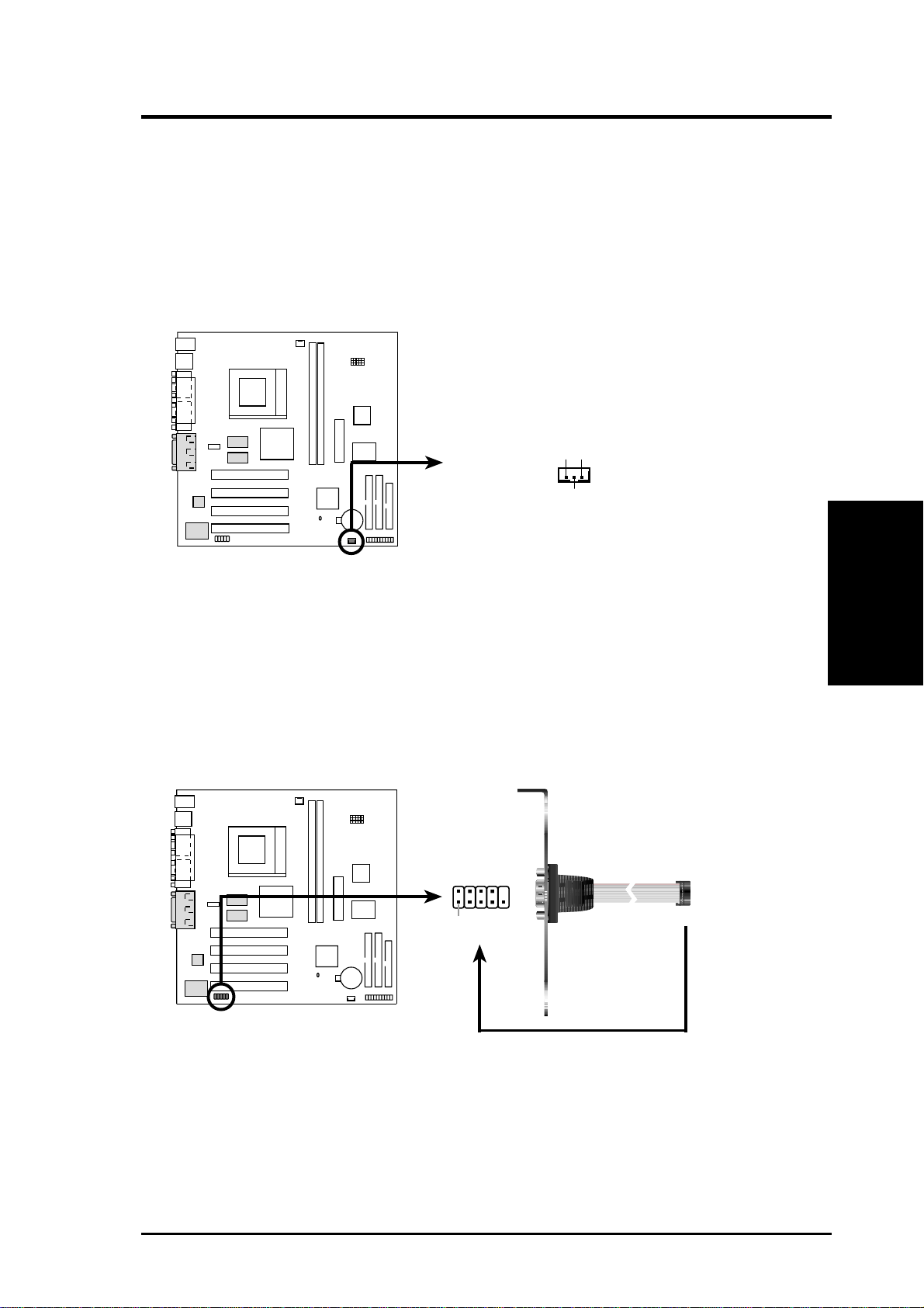
11) Wake-On-LAN Connector (3-pin WOL_CON)
This connector connects to a LAN card with a Wake-On-LAN output, such as
the ASUS PCI-L101 Ethernet card. The connector powers up the system when a
wakeup packet or signal is received through the LAN card.
IMPORTANT: This feature requires that your system has an ATX power supply with at least 720mA +5V standby power.
IMPORTANT: Requires an ATX power
supply with at least 720mA +5 volt
standby power
1
MEW-AM
+5 Volt Standby PME
Ground
MEW-AM Wake-On-LAN Connector
12) Serial Port Header (10-1 pin COM2)
The optional serial port bracket can be used to add an additional serial port for
additional serial devices.
Connectors
3. H/W SETUP
1
MEW-AM
MEW-AM Serial COM2 Bracket
ASUS MEW-AM User’s Manual 23
Pin 1
to COM2 Header
Page 24
3. HARDWARE SETUP
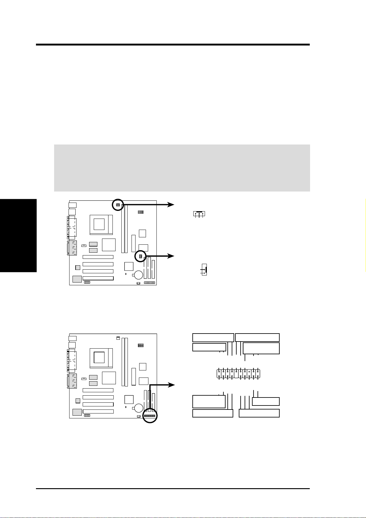
13) CPU Fan Connectors (3-pin CPU_FAN)
This connector supports a cooling fan of 350mA (4.2 Watts) or less. Orientate
the fan so that the heat sink fins allow airflow to go across the onboard heat
sink(s) instead of the expansion slots. Depending on the fan manufacturer, the
wiring and plug may be different. The red wire should be positive, while the
black should be ground. Connect the fan’s plug to the board taking into consid-
eration the polarity of the connector.
NOTE: The “Rotation” signal cannot be monitored on this motherboard.
WARNING! The CPU and/or motherboard will overheat if there is no airflow
across the CPU and onboard heatsinks. Damage may occur to the motherboard
and/or the CPU fan if these pins are incorrectly used. These are not jumpers,
do not place jumper caps over these pins.
3. H/W SETUP
Connectors
CPU Fan Power
GND
+12V
Rotation
1
MEW-AM
Chassis Fan Power
+12V
GND
MEW-AM 12-Volt Cooling Fan Power
The following PANEL illustration is used for items 14-21
Keyboard Lock
Message LED
Keylock
MSGLED-
MSGLED+
Ground
External SMI Lead
ExtSMI#
Speaker
Connector
Ground
+5V
Speaker
1
MEW-AM
Ground
IDELED-
PWRBTN
IDELED+
ATX Power
Switch*
HDLED
*
Requires an ATX power supply.
MEW-AM System Panel Connectors
24 ASUS MEW-AM User’s Manual
Reset Ground
Ground
PWRLED-
PWRLED+
PWRLED-
Reset SW
Power LED
Page 25

3. HARDWARE SETUP
14) Message LED Lead (2-pin LED)
This indicates whether a message has been received from a fax/modem. The
LED will remain lit when there is no signal and flash when there is data received. This function requires an ACPI OS as well as application and driver
support.
15) Keyboard Lock Switch Lead (2-pin KEYLOCK)
This 2-pin connector connects to the case-mounted key switch to allow keyboard locking.
16) System Management Interrupt Lead (2-pin EXSMI)
This allows the user to manually place the system into a suspend mode or “Green”
mode, where system activity is decreased to save electricity and expand the life
of certain components when the system is not in use. This 2-pin connector connects to the case-mounted suspend switch. If you do not have a switch for the
connector, you may use the “Turbo Switch.” SMI is activated when it detects a
short to open moment and therefore leaving it shorted will not cause any problems. This may require one or two presses depending on the position of the
switch. The keyboard can always allow wake-up but not the SMI lead.
17) System Warning Speaker Connector (4-pin SPEAKER)
This 4-pin connector connects to the case-mounted speaker . You may leave this
disconnected if you connect the chassis speaker to the INT_SPKA. All three
sources (LINE_OUT, INT_SPKA, SPEAKER) will allow you to here system
beeps and warnings. Only LINE_OUT will allow you to hear system beeps before the integrated audio has been properly initialized.
18) ATX Power Switch Lead (2-pin PWRSW)
The system power is controlled by a momentary switch connected to this lead.
Pressing the button once will switch the system between ON and SOFT OFF.
Pushing the switch while in the ON mode for more than 4 seconds will turn the
system off. The system power LED shows the status of the system’s power.
19) IDE Activity LED (2-pin HDLED)
This connector supplies power to the cabinet’s IDE activity LED. Read and
write activity by devices connected to the Primary or Secondary IDE connectors
will cause the LED to light up.
20) System Power LED Lead (3-1 pin PLED)
This 3-1 pin connector connects the system power LED, which lights when the
system is powered ON and flashes when it is in standby (suspend) mode.
Connectors
3. H/W SETUP
21) Reset Switch Lead (2-pin RESET)
This 2-pin connector connects to the case-mounted reset switch for rebooting
your computer without having to turn off your power switch. This is a preferred
method of rebooting to prolong the life of the system’s power supply.
ASUS MEW-AM User’s Manual 25
Page 26

3. H/W SETUP
Connectors
3. HARDWARE SETUP
22) Internal Audio Connector (4-pin CD_IN) (optional)
These connectors allow you to receive stereo audio input from such sound sources
as a CD-ROM, TV tuner, or MPEG card.
CD_IN
1
MEW-AM
MEW-AM Internal Audio Connector
23) ATX Power Supply Connector (20-pin block ATXPWR)
This connector connects to an ATX power supply. The plug from the power supply will only insert in one orientation because of the different hole sizes. Find the
proper orientation and push down firmly making sure that the pins are aligned.
Ground
Ground
Left Audio Channel
Right Audio Channel
IMPORTANT: Make sure that your ATX power supply can supply at least 10mA
on the +5-volt standby lead (+5VSB). You may experience difficulty in powering ON your system if your power supply cannot support the load. For WakeOn-LAN support, your ATX power supply must supply at least 720mA +5VSB.
1
MEW-AM
MEW-AM ATX Power Connector
+12.0 Volts
+5V Standby
Power Good
Ground
+5.0 Volts
Ground
+5.0 Volts
Ground
+3.3 Volts
+3.3 Volts
+5.0 Volts
+5.0 Volts
-5.0 Volts
Ground
Ground
Ground
Power Supply On
Ground
-12.0 Volts
+3.3 Volts
26 ASUS MEW-AM User’s Manual
Page 27

3. HARDWARE SETUP
3.9 Power Connection Procedures
1. After all connections are made, close the system case cover.
2. Be sure that all switches are off (in some systems, marked with
3. Connect the power supply cord to the power supply located on the back of
your system case according to your system user’s manual.
4. Connect the power cord to a power outlet that is equipped with a surge protector.
5. You may then turn on your devices in the following order:
a. Your monitor
b. External SCSI devices (starting with the last device on the chain)
c. Your system power
For ATX power supplies, you need to switch ON the power supply if a
switch is provided as well as press the ATX power switch on the front of
the case.
6. The power LED on the front panel of the system case will light. For ATX
power supplies, the system LED will light when the ATX power switch is
pressed. The LED on the monitor may light up or switch between orange and
green after the system’s if it complies with “green” standards or if it has a
power standby feature. The system will then run power-on tests. While the
tests are running, additional messages will appear on the screen. If you do not
see anything within 30 seconds from the time you turn on the power, the system may have failed a power-on test. Check your jumper settings and connections again or call your retailer for assistance.
).
3. H/W SETUP
Power Connections
7. During power-on, hold down <Delete> to enter BIOS setup. Follow the instructions in 4. BIOS SETUP.
* Powering Off your computer: You must first exit or shut down your operat-
ing system before switching off the power switch. For ATX power supplies,
you can press the ATX power switch after exiting or shutting down your operating system. If you use Windows 95/98, click the Start button, click Shut
Down, and then click Shut down the computer?. The power supply should
turn off after Windows shuts down.
NOTE: The message “Y ou can now safely turn of f your computer” will not appear
when shutting down with ATX power supplies.
ASUS MEW-AM User’s Manual 27
Page 28

4. BIOS SETUP
4. BIOS SETUP
4.1 Managing and Updating Your BIOS
4.1.1 Upon First Use of the Computer System
It is recommended that you save a copy of the original motherboard BIOS
along with a Flash Memory Writer utility (AFLASH.EXE) to a bootable
floppy disk in case you need to reinstall the BIOS later . AFLASH.EXE is a
Flash Memory Writer utility that updates the BIOS by uploading a new
BIOS file to the programmable flash ROM on the motherboard. This file
works only in DOS mode. To determine the BIOS version of your motherboard, check the last four numbers of the code displayed on the upper lefthand corner of your screen during bootup. Larger numbers represent a newer
BIOS file.
1. Type FORMAT A:/S at the DOS prompt to create a bootable system
floppy disk. DO NOT copy AUTOEXEC.BAT & CONFIG.SYS to the
disk.
2. Type COPY D:\AFLASH\AFLASH.EXE A:\ (assuming D is your CD-
4. BIOS SETUP
Updating BIOS
3. Reboot your computer from the floppy disk. NOTE: BIOS setup must
4. In DOS mode, type A:\AFLASH <Enter> to run AFLASH.
ROM drive) to copy AFLASH.EXE to the just created boot disk.
NOTE: AFLASH works only in DOS mode. It will not work with DOS
prompt in W indows and will not work with certain memory drivers that
may be loaded when you boot from your hard drive. It is recommended
that you reboot using a floppy.
specify “Floppy” as the first item in the boot sequence.
IMPORTANT! If “unknown” is displayed after Flash Memory:, the memory
chip is either not programmable or is not supported by the ACPI BIOS and therefore, cannot be programmed by the Flash Memory Writer utility.
ASUS MEW-AM User’s Manual28
Page 29

4. BIOS SETUP
5. Select 1. Save Current BIOS to File from the Main menu and press
<Enter>. The Save Current BIOS To File screen appears.
6. T ype a filename and the path, for example, A:\XXX-XX.XXX and then
press <Enter>.
4.1.2 Updating BIOS Procedures (only when necessary)
1. Download an updated ASUS BIOS file from the Internet (WWW or
FTP) (see ASUS CONTACT INFORMATION on page 3 for details)
and save to the disk you created earlier.
2. Boot from the disk you created earlier.
3. At the “A:\” prompt, type AFLASH and then press <Enter>.
4. At the Main Menu, type 2 and then press <Enter>. The Update BIOS
Including Boot Block and ESCD screen appears.
5. T ype the filename of your new BIOS and the path, for example, A:\XXX-
XX.XXX, and then press <Enter>.
NOTE: To cancel this operation, press <Enter>.
Updating BIOS
4. BIOS SETUP
ASUS MEW-AM User’s Manual 29
Page 30

4. BIOS SETUP
6. When prompted to confirm the BIOS update, press Y to start the up-
date.
7. The utility starts to program the new BIOS information into the flash
ROM. The boot block will be updated automatically only when necessary. This will minimize the chance of a failed updating. When the programming is finished, Flashed Successfully will be displayed.
4. BIOS SETUP
Updating BIOS
8. Follow the onscreen instructions to continue.
WARNING! If you encounter problems while updating the new BIOS,
DO NOT turn off your system since this might prevent your system from
booting up. Just repeat the process, and if the problem still persists, update the original BIOS file you saved to disk above. If the Flash Memory
Writer utility was not able to successfully update a complete BIOS file,
your system may not be able to boot up. If this happens, your system will
need servicing.
ASUS MEW-AM User’s Manual30
Page 31

4. BIOS SETUP
4.2 BIOS Setup Program
This motherboard supports a programmable BIOS that can be updated using the
provided utility as described in 4.1 Managing and Updating Your BIOS.
The utility is used if you are installing a motherboard, reconfiguring your system,
or prompted to “Run Setup”. This section describes how to configure your system
using this utility.
Even if you are not prompted to use the Setup program, at some time in the future
you may want to change the configuration of your computer. For example, you
may want to enable the Security Password Feature or make changes to the power
management settings. It will then be necessary to reconfigure your system using
the BIOS Setup program so that the computer can recognize these changes and
record them in the CMOS RAM of the BIOS.
The BIOS on the motherboard stores the Setup utility. When you start up the computer, the system provides you with the opportunity to run this program. This appears during the Power-On Self Test (POST). Press <Delete> to call up the Setup
utility . If you are a little bit late in pressing the mentioned key, POST will continue
with its test routines, thus preventing you from calling up Setup. If you still need to
call Setup, restart the system by pressing <Ctrl> + <Alt> + <Delete>, or by pressing the Reset button on the system chassis. You can also restart by turning the
system off and then back on again. But do so only if the first two methods fail.
The Setup program has been designed to make it as easy to use as possible. It is a
menu-driven program, which means you can scroll through the various sub-menus
and make your selections among the predetermined choices.
To access the BIOS Setup program, press the <Delete> key after
the computer has run through its POST.
NOTE: Because the BIOS software is constantly being updated, the following
BIOS screens and descriptions are for reference purposes only and may not reflect your BIOS screens exactly.
4. BIOS SETUP
Program Information
ASUS MEW-AM User’s Manual 31
Page 32

4. BIOS SETUP
4.2.1 BIOS Menu Bar
The top of the screen has a menu bar with the following selections:
MAIN Use this menu to make changes to the basic system configuration.
ADVANCED Use this menu to enable and make changes to the advanced
features.
POWER Use this menu to configure and enable Power Management
features.
BOOT Use this menu to configure the default system device used to lo-
cate and load the Operating System.
EXIT Use this menu to exit the current menu or specify how to exit the
Setup program.
To access the menu bar items, press the right or left arrow key on the keyboard
until the desired item is highlighted.
4.2.2 Legend Bar
At the bottom of the Setup screen you will notice a legend bar. The keys in the
legend bar allow you to navigate through the various setup menus. The following
table lists the keys found in the legend bar with their corresponding alternates and
Menu Introduction
4. BIOS SETUP
functions.
Navigation Key(s) Function Description
<F1> or <Alt + H> Displays the General Help screen from anywhere in the BIOS
<Esc> Jumps to the Exit menu or returns to the main menu from a sub-
← or → (keypad arrow) Selects the menu item to the left or right
↑ or ↓ (keypad arrow) Moves the highlight up or down between fields
- (minus key) Scrolls backward through the values for the highlighted field
+ (plus key) or spacebar Scrolls forward through the values for the highlighted field
<Enter> Brings up a selection menu for the highlighted field
<Home> or <PgUp> Moves the cursor to the first field
<End> or <PgDn> Moves the cursor to the last field
Setup
menu
<F5> Resets the current screen to its Setup Defaults
<F10> Saves changes and exits Setup
ASUS MEW-AM User’s Manual32
Page 33

4. BIOS SETUP
General Help
In addition to the Item Specific Help window, the BIOS setup program also provides a General Help screen. This screen can be called up from any menu by simply pressing <F1> or the <Alt> + <H> combination. The General Help screen lists
the legend keys with their corresponding alternates and functions.
Saving Changes and Exiting the Setup Program
See 4.8 Exit Menu for detailed information on saving changes and exiting the
setup program.
Scroll Bar
When a scroll bar appears to the right of a help window, it indicates that there is
more information to be displayed that will not fit in the window. Use <PgUp> and
<PgDn> or the up and down arrow keys to scroll through the entire help document. Press <Home> to display the first page, press <End> to go to the last page.
To exit the help window, press <Enter> or <Esc>.
Sub-Menu
Note that a right pointer symbol (as shown in the left view)
appears to the left of certain fields. This pointer indicates that
a sub-menu can be launched from this field. A sub-menu contains additional options for a field parameter . To call up a submenu, simply move the highlight to the field and press <Enter>. The sub-menu will then immediately appear. Use the
legend keys to enter values and move from field to field within
a sub-menu just as you would within a menu. Use the <Esc>
key to return to the main menu.
Take some time to familiarize yourself with each of the legend keys and their
corresponding functions. Practice navigating through the various menus and submenus. If you accidentally make unwanted changes to any of the fields, use the set
default hot key <F5>. While moving around through the Setup program, note that
explanations appear in the Item Specific Help window located to the right of each
menu. This window displays the help text for the currently highlighted field.
4. BIOS SETUP
Menu Introduction
NOTE: The item heading in square brackets represents the default setting for
that field.
ASUS MEW-AM User’s Manual 33
Page 34

4. BIOS SETUP
4.3 Main Menu
When the Setup program is accessed, the following screen appears:
4. BIOS SETUP
Main Menu
System Time [XX:XX:XX]
Sets your system to the time that you specify (usually the current time). The
format is hour, minute, second. Valid values for hour, minute and second
are Hour: (00 to 23), Minute: (00 to 59), Second: (00 to 59). Use the
<Tab> or <Shift> + <Tab> keys to move between the hour, minute, and
second fields.
System Date [XX/XX/XXXX]
Sets your system to the date that you specify (usually the current date). The
format is month, day , year . Valid values for month, day, and year are Month:
(1 to 12), Day: (1 to 31), Year: (100 year range). Use the <Tab> or <Shift>
+ <Tab> keys to move between the month, day, and year fields.
Legacy Diskette A [1.44M, 3.5 in.], Legacy Diskette B [None]
Sets the type of floppy drives installed. Configuration options: [None] [360K,
5.25 in.] [1.2M , 5.25 in.] [720K , 3.5 in.] [1.44M, 3.5 in.] [2.88M, 3.5 in.]
ASUS MEW-AM User’s Manual34
Page 35

4. BIOS SETUP
4.3.1 Primary & Secondary Master/Slave
NOTE: Before attempting to configure a hard disk drive, make sure you
have the configuration information supplied by the manufacturer of the
drive. Incorrect settings may cause your system to not recognize the installed hard disk. To allow the BIOS to detect the drive type automatically, select [Auto].
Type [Auto]
Select [Auto] to automatically detect an IDE hard disk drive. If automatic
detection is successful, the correct values will be filled in for the remaining
fields on this sub-menu. If automatic detection fails, your hard disk drive
may be too old or too new . Y ou can try updating your BIOS or enter the IDE
hard disk drive parameters manually.
NOTE: After the IDE hard disk drive information has been entered into
BIOS, new IDE hard disk drives must be partitioned (such as with FDISK)
and then formatted before data can be read from and write on. Primary IDE
hard disk drives must have its partition set to active (also possible with
FDISK).
4. BIOS SETUP
Master/Slave Drives
Other options for the Type field are:
[None] - to disable IDE devices
ASUS MEW-AM User’s Manual 35
Page 36

4. BIOS SETUP
IMPORT ANT: If your hard disk was already formatted on an older previous system,
incorrect parameters may be detected. You will need to enter the correct parameters
manually or use low-level format if you do not need the data stored on the hard disk.
If the parameters listed differ from the ones used when the disk was
formatted, the disk will not be readable. If the auto-detected parameters
do not match the ones that should be used for your disk, you should enter
the correct ones manually by setting [User Type HDD].
[User Type HDD]
Master/Slave Drives
4. BIOS SETUP
Manually enter the number of cylinders, heads and sectors per track for
your drive. Refer to your drive documentation or look on the drive for this
information. If no drive is installed or if you are removing a drive and not
replacing it, select [None].
Translation Method [LBA]
Select the hard disk drive type in this field. When Logical Block Addressing
is enabled, 28-bit addressing of the hard drive is used without regard for
cylinders, heads, or sectors. Note that Logical Block Access may decrease
the access speed of the hard disk. However, LBA Mode is necessary for
drives with greater than 504MB in storage capacity . Configuration options:
[LBA] [LARGE] [Normal] [Match Partition Table] [Manual]
Cylinders
This field configures the number of cylinders. Refer to your drive documentation to determine the correct value to enter into this field. NOTE: To
make changes to this field, the Type field must be set to [User Type HDD]
and the Translation Method field must be set to [Manual].
ASUS MEW-AM User’s Manual36
Page 37

4. BIOS SETUP
Head
This field configures the number of read/write heads. Refer to your drive
documentation to determine the correct value to enter into this field. NOTE:
To make changes to this field, the Type field must be set to [User Type
HDD] and the Translation Method field must be set to [Manual].
Sector
This field configures the number of sectors per track. Refer to your drive
documentation to determine the correct value to enter into this field. NOTE:
To make changes to this field, the Type field must be set to [User Type
HDD] and the Translation Method field must be set to [Manual].
CHS Capacity
This field shows the drive’s maximum CHS capacity calculated automati-
cally by the BIOS from the drive information you entered.
Maximum LBA Capacity
This field shows the drive’s maximum LBA capacity calculated automati-
cally by the BIOS from the drive information you entered.
Multi-Sector Transfers [Maximum]
This option automatically sets the number of sectors per block to the highest number supported by the drive. This field can also be configured manually . Note that when this field is automatically configured, the set value may
not always be the fastest value for the drive. Refer to the documentation that
came with your hard drive to determine the optimal value and set it manually. NOTE: To make changes to this field, the Type field must be set to
[User Type HDD]. Configuration options: [Disabled] [2 Sectors] [4 Sectors] [8 Sectors] [16 Sectors] [32 Sectors] [Maximum]
SMART Monitoring [Disabled]
This allows the enabling or disabling of the S.M.A.R.T. (Self-Monitoring,
Analysis and Reporting Technology) system which utilizes internal hard
disk drive monitoring technology . This feature is normally disabled because
system resources used in this feature may decrease system performance.
Configuration options: [Disabled] [Enabled]
PIO Mode [4]
This option lets you set a PIO (Programmed Input/Output) mode for the
IDE device. Modes 0 through 4 provide successively increased performance.
Configuration options: [0] [1] [2] [3] [4]
4. BIOS SETUP
Master/Slave Drives
Ultra DMA Mode [Disabled]
Ultra DMA capability allows improved transfer speeds and data integrity
for compatible IDE devices. Set to [Disabled] to suppress Ultra DMA capability. NOTE: To make changes to this field, the Type field must be set to
[User Type HDD]. Configuration options: [0] [1] [2] [3] [4] [Disabled]
ASUS MEW-AM User’s Manual 37
Page 38

4. BIOS SETUP
Other options for “Type:” are:
[CD-ROM] - for IDE CD-ROM drives
[LS-120] - for LS-120 compatible floppy disk drives
[ZIP-100] - for ZIP-100 compatible disk drives
[MO] - for IDE magneto optical disk drives
[Other ATAPI Device] - for IDE devices not listed here
After using the legend keys to make your selections on this sub-menu, press
the <Esc> key to exit back to the Main menu. When the Main menu appears, you will notice that the drive size appear in the field for the hard disk
drive that you just configured.
4.3.2 Keyboard Features
Keyboard Features
4. BIOS SETUP
Boot Up NumLock Status [On]
This field controls the state of the NumLock key when the system boots.
When switched on, the numeric keypad generates numbers instead of controlling cursor operations. Configuration options: [Off] [On]
ASUS MEW-AM User’s Manual38
Page 39

4. BIOS SETUP
Keyboard Auto-Repeat Rate [30/Sec]
This field controls the speed at which the system registers repeated keystrokes. Configuration options: [6/Sec] [8/Sec] [10/Sec] [12/Sec] [15/Sec]
[20/Sec] [24/Sec] [30/Sec]
Keyboard Auto-Repeat Delay [1/2 Sec]
This field sets the delay before keystrokes begin to repeat. Configuration
options: [1/4 Sec] [1/2 Sec] [3/4 Sec] [1 Sec]
CPU Type, CPU Speed, Cache RAM, Installed Memory
These fields display the CPU and memory information detected by the system during bootup. You do not need to make changes to these fields. These
are display only fields.
ASUS MEW-AM User’s Manual 39
4. BIOS SETUP
Keyboard Features
Page 40

4. BIOS SETUP
4.4 Advanced Menu
Advanced Menu
4. BIOS SETUP
Plug & Play O/S [No]
This field allows you to use a Plug-and-Play (PnP) operating system to configure the PCI bus slots instead of using the BIOS. When [Yes] is selected,
interrupts may be reassigned by the OS. When a non-PnP OS is installed or
you want to prevent reassigning of interrupt settings, select the default setting of [No]. Configuration options: [No] [Yes]
Boot Virus Detection [Enabled]
This field allows you to set boot virus detection, ensuring a virus-free boot
sector. With this new solution, your computer is protected against boot virus threats earlier in the boot cycle, that is, before they have a chance to load
into your system. The system halts and displays a warning message when it
detects a virus. If this occurs, you can either allow the operation to continue
or use a virus-free bootable floppy disk to restart and investigate your system. Because of conflicts with new operating systems, for example, during
installation of new software, you may have to set this to [Disabled] to prevent write errors. Configuration options: [Disabled] [Enabled]
Quick Power On Self Test [Enabled]
This field speeds up the Power-On Self Test (POST) routine by skipping
retesting a second, and third time. A complete test of the system memory
can be done on the first test. Configuration options: [Disabled] [Enabled]
ASUS MEW-AM User’s Manual40
Page 41

4. BIOS SETUP
Halt On [All Errors]
This field determines which types of errors will cause the system to halt.
Configuration options: [All Errors] [No Error] [All but Keyboard] [All but
Disk] [All but Disk/Keyboard]
Reset Configuration Data [No]
The Extended System Configuration Data (ESCD) contains information
about non-PnP devices and holds the complete record of how the system
was configured the last time it was booted. Set this field to [Y es] only when
you want to clear the ESCD. Configuration options: [No] [Yes]
Onboard PCI IDE Enable [Both]
You can select to enable the primary IDE channel, secondary IDE channel,
both, or disable both channels (for systems with only SCSI drives). Configuration options: [Both] [Primary] [Secondary] [Disabled]
ASUS MEW-AM User’s Manual 41
Advanced Menu
4. BIOS SETUP
Page 42

4. BIOS SETUP
4.4.1 I/O Device Configuration
Floppy Disk Access Control [R/W]
When set to [Read Only], this field protects files from being copied to floppy
disks by allowing reads from the floppy disk drive but not writes. The setup
default [R/W] allows both reads and writes. Configuration options: [R/W]
[Read Only]
I/O Device Config.
4. BIOS SETUP
Serial Port A [3F8H/IRQ4], Serial Port B [2F8H/IRQ3]
These fields allow you to set the addresses for the onboard serial connectors.
Serial Port A and Serial Port B must have different addresses. Configuration
options: [3F8H/IRQ4] [2F8H/IRQ3] [3E8H/IRQ4] [2E8H/IRQ3] [Disabled]
Parallel Port [378H/IRQ7]
This field sets the address of the onboard parallel port connector. If you
disable this field, Parallel Port Mode configuration will not be available.
Configuration options: [Disabled] [378H/IRQ7] [278H/IRQ5]
Parallel Port Mode [EPP1.9+SPP]
This field allows you to set the operation mode of the parallel port. Configuration options: [SPP] [EPP1.9+SPP] [ECP] [ECP+EPP1.9] [Mono-directional] [EPP1.7+SPP] [ECP+EPP1.7]
ASUS MEW-AM User’s Manual42
Page 43

4. BIOS SETUP
4.5 Security Menu
Supervisor Password / User Password
These two options set the system passwords. Supervisor Password sets a
password that will be used to protect the system and the Setup utility; User
Password sets a password that will be used exclusively on the system. By
default, the system comes without any passwords. To specify a password,
highlight the type you want and then press <Enter>. A password prompt
appears on the screen. T ake note that the password is case sensitive, and can
be up to 8 alphanumeric characters long. Type in your password and then
press <Enter>. The system confirms your password by asking you to type it
again.
Password on boot [Disabled]
To implement password protection during bootup, set your password in the
Supervisor Password / User Password fields and select [Enabled] for this
field. The passwords will not take effect if you disable this field.
Security Menu
4. BIOS SETUP
ASUS MEW-AM User’s Manual 43
Page 44

4. BIOS SETUP
Forgot the password?
If you forgot the password, you can clear the password by erasing the CMOS
Real Time Clock (RTC) RAM. The RAM data containing the password
information is powered by the onboard button cell battery. To erase the
R TC RAM: (1) Unplug your computer, (2) Short the solder points, (3) Turn
ON your computer, (4) Hold down <Delete> during bootup and enter BIOS
setup to re-enter user preferences.
4. BIOS SETUP
Security Menu
ASUS MEW-AM User’s Manual44
Page 45

4. BIOS SETUP
4.6 Power Menu
4.6.1 General Power Settings
Auto Suspend Timeout [20 Min]
This field sets the time period of inactivity before the system goes into suspend mode. Configuration options: [Off] [1~2 Min] [2~3 Min]...[1 Hour]
HDD Power Down [15 Min]
This field shuts down any IDE hard disk drives in the system after a period of
inactivity as set in this user-configurable field. This feature does not af fect SCSI
hard drives. Configuration options: [Disabled] [1 Min] [2 Min] ...[15 Min]
State after a Power Failure [Auto]
This allows you to set whether you want your system to reboot after the
power has been interrupted. [Off] leaves your system off and [On] reboots
your system. [Auto] returns your computer back to the state it was in before
the power failure. Configuration options: [Off] [Auto] [On]
4.6.2 Power-Up Events
On External Activity
Serial Port [Off]
This feature allows your computer to be powered up from Soft-off mode
when the device connecting to the serial port (such as an external modem)
reveives a call. Configuration options: [Off] [On]
Power Menu
4. BIOS SETUP
PCI Bus [Off]
This feature allows your computer to be powered up from Soft-off mode
when a PCI device (such as a modem or network card) receives a call. Configuration options: [Off] [On]
ASUS MEW-AM User’s Manual 45
Page 46

4. BIOS SETUP
4.7 Boot Menu
4.7.1 Boot Sequence
The Boot menu allows you to select among the four possible types of boot
devices listed using the up and down arrow keys. By using the <+> or
<Space> key, you can promote devices and by using the <-> key, you can
4. BIOS SETUP
Boot Menu
demote devices. Promotion or demotion of devices alters the priority which
the system uses to search for a boot device on system power up. Configuration options: [Removable Devices] [ATAPI CD-ROM] [IDE Hard Drive]
[Other Boot Device]
Removable Device [Legacy Floppy]
Configuration options: [Disabled] [Legacy Floppy] [LS120] [ZIP-100]
[ATAPI MO]
ATAPI CD-ROM
This field allows you to select which ATAPI CD-ROM drive to use in the
boot sequence. Pressing [Enter] will show the product IDs of all your connected ATAPI CD-ROM drives.
IDE Hard Drive
This field allows you to select which IDE hard disk drive to use in the boot
sequence. Pressing [Enter] will show the product IDs of all connected IDE
hard disk drives.
Other Boot Device Select [INT18 Device (Network)]
Configuration options: [Disabled] [SCSI Boot Device] [INT18 Device (Network)]
ASUS MEW-AM User’s Manual46
Page 47

4. BIOS SETUP
4.8 Exit Menu
Once you have made all of your selections from the various menus in the
Setup program, you should save your changes and exit Setup. Select Exit
from the menu bar to display the following menu:
NOTE: Pressing <Esc> does not exit this menu. You must select one of the
options from this menu or <F10> from the legend bar to exit this menu.
Exit Saving Changes
Once you are finished making your selections, choose this option from the
Exit menu to ensure the values you selected are saved to the CMOS RAM.
The CMOS RAM is sustained by an onboard backup battery and stays on
even when the PC is turned off. Once this option is selected, a confirmation is asked. Select [Yes] to save changes and exit.
NOTE: If you attempt to exit the Setup program without saving your changes,
the program will prompt you with a message asking if you want to save your
changes before exiting. Pressing <Enter> will then save changes while exiting.
Exit Discarding Changes
This option should only be used if you do not want to save the changes you
have made to the Setup program. If you have made changes to fields other
than system date, system time, and password, the system will ask for confirmation before exiting.
Load Setup Defaults
This option allows you to load the default values for each of the parameters
on the Setup menus. When this option is selected or if <F5> is pressed, a
confirmation is requested. Select [Yes] to load default values. You can now
select Exit Saving Changes or make other changes before saving the val-
ues to the non-volatile RAM.
Exit Menu
4. BIOS SETUP
ASUS MEW-AM User’s Manual 47
Page 48

4. BIOS SETUP
(This page was intentionally left blank.)
4. BIOS SETUP
ASUS MEW-AM User’s Manual48
Page 49

5. SOFTWARE SETUP
5.1 ASUS Smart Motherboard Support CD
NOTE: The support CD contents are subject to change at any time without notice.
T o begin using your support CD disc, just insert it into your CD-ROM drive and the
support CD installation menu should appear. If the menu does not appear, double
click or run D:\ASSETUP.EXE (assuming that your CD-ROM drive is drive D:).
5.1.1 Support CD Main Menu
Motherboard Info
Browse This CD
User’s Manual
Technical Support Form
Read Me
Exit
Main Menu (home button
only on other screens)
Back (arrow button only
on certain screens)
Navigation Button Descriptions
Motherboard Info displays information on your motherboard, BIOS, and CPU.
Browse This CD allows you to see the contents of the ASUS Support CD.
User’s Manual displays the motherboard user’s manual in pdf format.
Technical Support Form opens up a blank Technical Support Request Form for
you to fill and print out when you run into technical difficulties and need technical
assistance.
Read Me opens up a file containing additional notes.
Home returns you to the main menu of the support CD. (only on other screens)
Exit allows you to close the support CD.
Back returns you one screen back on the support CD.
ASUS MEW-AM User’s Manual 49
Page 50

5. SOFTWARE SETUP
5.1.2 Support CD Submenus
NOTE: The support CD contents are subject to change at any time without notice.
Installation Submenu
ASUS Probe: Not available on this motherboard.
ASUS LiveUpdate: Installs a program to help you
update your BIOS or download a BIOS image file.
Driver: Installs the necessary drivers for your on-
board components to work properly.
Other: Allows you to install additional software and
utilities to help you make better use of your new
motherboard.
Driver
Network Driver Setup: Not available on this moth-
erboard.
5. S/W SETUP
Windows 98
VGA Driver Setup: Intel’s 810 System and Graph-
ics Controller Driver.
Audio Driver Setup: See 5.3.2 PCI Multimedia
Audio Device Found.
Other
INF Update Utility for 810 Chipset: This utility in-
stalls INF files in Windows for the following items:
System and Graphics, LPC Interface, SM Bus, PCI
Bridge, Bus Master IDE, USB Host, Controllers
Intel Security Driver: Installs a security controller
for your Windows 95/98. Read the Release Notes dur ing installation and the Readme file at the end of the
installation for more information.
YAMAHA S-YXG50: Installs Yamaha’s software
synthesizer for playing MIDI files on a personal com-
puter through software alone without usinga hardware sound source such as a sound card. (YAMAHA, Soft Synthesizer, S-YXG50, Midplug, and XG
studio are all trademarks of Yamaha Corp. Copyright 1996-1999 Yamaha Corporation, All Rights Reserved)
YAMAHA XGStudio: Installs Yamaha’s XGStudio Mixer.
Microsoft DirectX 6.0 Driver: Installs Microsoft’s DirectX 6.0 driver for Windows 95/98. Microsoft’s
DirectX is necessary for most multimedia applications to run.
50 ASUS MEW-AM User’s Manual
Page 51

5. SOFTWARE SETUP
PC-cillin 98: Installs Trend’s PC-cillin virus protection software. V iew the online help for more informa-
tion.
Adobe Acrobat Reader: Installs the Adobe Acrobat Reader software necessary to view user’s manuals
saved in PDF format. Updated or other language versions of this motherboard's manual is available in
PDF format at any of our web sites.
Exit: Returns to the Installation menu.
DOS Utility Submenu
Flash BIOS Utility (DOS V ersion): Provides information on the Flash BIOS utility (AFLASH.EXE).
Choose “Restart in MS-DOS mode” then type
“aflash” from the AFLASH folder on the support CD.
ASUS Contact Information Submenu
This page gives Marketing and Technical Support
contact information which is similar to the one in
the beginning of this User’s Manual.
Windows 98
5. S/W SETUP
ASUS MEW-AM User’s Manual 51
Page 52

5. SOFTWARE SETUP
5.2 Operating Systems
Although ASUS motherboards passed testing on several operating systems, the operating system shown in these sections will be that of Microsoft’s Windows 98. You
should always use the latest operating system and updates when using new hardware to ensure full compliancy . For W indows 95, you must use OSR 2.0 or later . For
Windows NT 4.0, you must use Service Pack 3.0 or later.
5.3 Starting Windows For the First Time
When you start Windows 98 for the first time after installing your motherboard,
Windows will detect all plug-and-play devices. You can either follow the Add New
Hardware Wizard to install the device drivers or click Cancel. When prompted to
restart, select No and then follow the normal setup procedures later in this section.
IMPORTANT: Selecting No for the initial restart prompt is a necessary step
because W indows may load an older display driver that is incompatible with the
onboard VGA chip. Always use the driver available on the ASUS Support CD or
an applicable driver update from your ASUS vendor or from the ASUS web site.
5. S/W SETUP
Windows 98
NOTE: Because there are various motherboard settings, options, and expansion
cards, the following can only be used as a general reference and not an exact reflection of your system.
52 ASUS MEW-AM User’s Manual
Page 53

5. SOFTWARE SETUP
5.3.1 Intel 82802 Firmware Hub Device Found
(2) Click here and
(1) Click here.
(3) Insert the Windows 98
CD into your CD-ROM
drive, browse to it, and
then click here.
then click Next.
(4) Click here.
ASUS MEW-AM User’s Manual 53
Windows 98
5. S/W SETUP
Page 54

5. SOFTWARE SETUP
5.3.2 PCI Multimedia Audio Device Found
(2) Click here and
(1) Click here.
(3) Browse to the here and
then click Next.
then click Next.
5. S/W SETUP
Windows 98
(5) Click here.
(4) Click here.
(6) Click here.
54 ASUS MEW-AM User’s Manual
Page 55

5. SOFTWARE SETUP
5.4 ASUS LiveUpdate
Insert the Support CD that came with your motherboard into your CD-ROM drive
or double-click the CD drive icon in My Computer to bring up the setup screen.
(1) Click here.
(2) Click here.
(3) Click here.
(5) Click here.
(4) Click here.
(6) Click here.
Windows 98
5. S/W SETUP
ASUS MEW-AM User’s Manual 55
55
Page 56

5. SOFTWARE SETUP
5.5 Driver
5.5.1 VGA Driver Setup
Insert the Support CD that came with your motherboard into your CD-ROM drive
or double-click the CD drive icon in My Computer to bring up the setup screen.
(1) Click here.
(2) Click here.
5. S/W SETUP
Windows 98
(3) Click here.
(6) Click here. (7) Click here.
(4) Click here.
(5) Click here.
(8) Click here to
install to the
default folder.
56 ASUS MEW-AM User’s Manual
(9) Click here.
Page 57

5. SOFTWARE SETUP
(10) Click here and then
click Finish to restart.
(11) Click here.
(12) Click here.
(14) Click here.
(16) Click here.
(13) Click here.
(15) Click here.
(17) Click here.
(18) Br owse to
E:\VGA\WIN98 and
then click here.
(19) To install other driv-
ers, click here and
then click Finish.
ASUS MEW-AM User’s Manual 57
Page 58

5. SOFTWARE SETUP
5.6 Other
5.6.1 INF Update Utility for 810 Chipset
Insert the Support CD that came with your motherboard into your CD-ROM drive
or double-click the CD drive icon in My Computer to bring up the setup screen.
(1) Click here.
(2) Click here.
(3) Click here.
(5) Click her e only after you
have read the license
agreement.
(4) Click here.
(6) Click here.
(7) Click here to install the
driver to the default folder .
(8) Click here and then follow
the online instructions.
58 ASUS MEW-AM User’s Manual
Page 59

5. SOFTWARE SETUP
5.6.2 Intel Security Driver
Insert the Support CD that came with your motherboard into your CD-ROM drive
or double-click the CD drive icon in My Computer to bring up the setup screen.
(1) Click here.
(2) Click here.
(3) Click here.
(4) Click here.
(5) Click here. (6) Click here.
(8) Click here and then follow
(7) Click here.
the online instructions.
ASUS MEW-AM User’s Manual 59
Page 60

5. SOFTWARE SETUP
5.6.3 YAMAHA S-YXG50
Insert the Support CD that came with your motherboard into your CD-ROM drive
or double-click the CD drive icon in My Computer to bring up the setup screen.
(1) Click here.
(3) Click here.
(2) Click here.
(4) Click here.
(6) Click here.
(5) Enter the information requested
and the click here
(7) Click here only if you accept
the terms of the agreement.
*
.
* The serial number can be found on the software license
agreement card.
60 ASUS MEW-AM User’s Manual
(8) Click here.
Page 61

5. SOFTWARE SETUP
(9) Click here.
(10) Click here.
(11) Click here.
ASUS MEW-AM User’s Manual 61
Page 62

5. SOFTWARE SETUP
5.6.4 YAMAHA XGStudio
Insert the Support CD that came with your motherboard into your CD-ROM drive
or double-click the CD drive icon in My Computer to bring up the setup screen.
(2) Click here.
(1) Click here.
(3) Click here.
(5) Click here only after
you have carefully read
the license agreement.
(7) Click here.
(4) Click here.
(6) Click here.
(8) Click here.
62 ASUS MEW-AM User’s Manual
(9) Click here.
Page 63

5. SOFTWARE SETUP
5.6.5 Microsoft DirectX 6.0 Driver
Insert the Support CD that came with your motherboard into your CD-ROM drive
or double-click the CD drive icon in My Computer to bring up the setup screen.
(1) Click here.
(3) Click here.
(2) Click here.
(4) Click here only after you
have read the license
agreement.
(5) Click here.
(6) Click here.
ASUS MEW-AM User’s Manual 63
Windows 98
5. S/W SETUP
Page 64

5. SOFTWARE SETUP
5.6.6 PC-cillin 98
Insert the Support CD that came with your motherboard into your CD-ROM drive
or double-click the CD drive icon in My Computer to bring up the setup screen.
(1) Click here.
(3) Click here.
(2) Click here.
(4) Click here.
5. S/W SETUP
Windows 98
64 ASUS MEW-AM User’s Manual
(5) Click here only if you
accept the terms of the
license agreement.
(7) Click here.
(6) Click here.
(8) Click here and then
follow the online
instructins to finish
installation.
Page 65

5. SOFTWARE SETUP
5.6.7 Adobe Acrobat Reader V4.0
Insert the Support CD that came with your motherboard into your CD-ROM drive
or double-click the CD drive icon in My Computer to bring up the setup screen.
(2) Click here.
(1) Click here.
(3) Click here.
(5) Click here only if you
accept the terms of the
license agreement.
(7) T o install other drivers
or programs, click here
and then click Finish.
(4) Click here.
(6) Click here.
Windows 98
5. S/W SETUP
ASUS MEW-AM User’s Manual 65
Page 66

5. SOFTWARE SETUP
5.7 Uninstalling Programs
Add/Remove Programs is a basic component within Windows. You may use this
function if a program does not provide its own uninstall program.
5. S/W SETUP
Windows 98
66 ASUS MEW-AM User’s Manual
Page 67

6. SOFTWARE REFERENCE
6.1 Display Properties
The motherboard’s built-in 2D/3D AGP VGA supports professional graphics de-
sign, gaming, learning, and business applications.
NOTE: Depending on your system configuration, components, and options, your
system may not show all of the settings displayed in the following pictures.
Windows 98
T o open the Properties dialog box, right-click the desktop and select Properties, then
select the Settings tab, and the Advanced button.
General
The Display box displays the current font size
of the selected monitor . To use a different font
size, click the arrow, and then click the font
size you want.
The Compatibility box allows you to specify
when to apply changes to system color settings. NOTE: Some programs might not dis-
play colors correctly without being restarted
after you make changes. To avoid this problem, close the program, change the color settings, and then open the program again.
6. S/W REFERENCE
Adapter
Shows what type of display adapter you are
currently using. To install the software for a
new display adapter, click Change.
For detailed instructions and refer ences to software and utilities, please use the
programs’ online help and electronic documentations.
ASUS MEW-AM User’s Manual 67
Page 68

6. S/W REFERENCE
6. S/W REFERENCE
Display Properties
Windows 98
Monitor
Shows what type of monitor you are currently
using. T o install the software for a new monitor, click Change.
Performance
Specifies the degree of acceleration you want
for your graphics hardware. Full acceleration
is the fastest and is recommended for most
computers. If your ocmputer is having problems and you suspect graphics acceleration
to be the cause, use the highest setting at
which you do not have problems.
6. SOFTWARE REFERENCE
Color Management
Lists all the color profile currently associated
with your monitor. Click a profile to make it
the active profile. Otherwise, the default profile is the active profile.
ASUS MEW-AM User’s Manual68
Page 69

6. SOFTWARE REFERENCE
Information
Gives information on your graphics device
such as chipset, memory , BIOS, and drivers.
Internet links are also available for easy access to the ASUS Web page for new updated
drivers and notices.
Color (Desktop)
Allows you to adjust the quality of your display according to your preference. Gamma
correction is available only in 16-bit color
and 24-bit color (true color, 16.7M-color)
modes. In 16-bit color and 8-bit color (standard color, 256-color) modes, the gamma cor rection function is not supported.
Windows 98
Display Properties
6. S/W REFERENCE
6. S/W REFERENCE
Color (Direct3D/Game)
This is the same as the color adjustments for
the desktop but this applies to direct3D applications and games.
ASUS MEW-AM User’s Manual 69
Page 70

6. S/W REFERENCE
6. S/W REFERENCE
Display Properties
Windows 98
Display
Allows you to adjust the display position,
size, and refresh rate.
6. SOFTWARE REFERENCE
Change current refresh rate
Allows you to adjust the currently displayed resolution refresh rate.
Change refresh rate
Allows you to adjust the default refresh rates for
each resolution and color settings.
Display (2)
Allows you to select the output device–PC
Monitor or Digital Flat Panel (DFP)
NOTE: DFP only works in 1024x768 or less
resolutions.
ASUS MEW-AM User’s Manual70
Page 71

6. SOFTWARE REFERENCE
6.2 ASUS Update
ASUS Update is a utility that allows you to update your motherboard’s BIOS
and other drivers. The use of this utility with the Internet requires that you
are properly connected to the internet through an Internet Service Provider .
Start ASUS Update
Launch the utility from Start | Programs |
ASUS Utility | ASUS Update V2.00
Select the update method:
Update BIOS from local disk allows you to
specify a BIOS image file on your local disk.
Windows 98
6. S/W REFERENCE
Update BIOS/Driver from Internet will automatically download an updated BIOS image file from the Internet if available and start
the update process.
Download BIOS/Driver from Internet allows you to download a BIOS image file for
you to upate later.
Select an internet site
Choose the site that is closest to you or choose
Auto Select.
Updating from local disk
If you chose Update BIOS from local disk,
you will be prompted to locate the file.
ASUS MEW-AM User’s Manual 71
Page 72

6. SOFTWARE REFERENCE
6. S/W REFERENCE
Windows 98
You will be prompted that running applications will be closed in order to continue with
the BIOS update process.
ASUS MEW-AM User’s Manual72
Page 73

6. SOFTWARE REFERENCE
6.3 Using Yamaha XGstudio Player
To start the Yamaha XGstudio, click Start, point to Programs, point to YAMAHA
XGstudio, and then click XGstudio Player.
6.3.1 Yamaha XGstudio Player Control Panel
Closes the player . NOTE: You can also close
the player by pressing <Alt>+<F4>.
Minimizes the player to an icon.
Displays the Set Play List dialog box where
you can create a list of songs to play automatically. NOTE: You can also display the
Set Play List dialog box by pressing
<Ctrl>+<O>.
Designates the song after the song currently
playing as the new current-play song.
Designates the last song in the Play List as
the new current-play song.
Displays the control panel for the Soft Synthesizer features.
Speeds up the tempo of the song being played.
Windows 98
YAMAHA S-YXG50
6. S/W REFERENCE
6. S/W REFERENCE
Loads and plays the MIDO file currently selected in Play List. When all the songs in the
Play List have finished, playing stops automatically and the song at the beginning of
the list is designated as the current-play song.
Pauses the playing of a song. Click this button again or click to resume playing.
Stops the playing of a song and returns the
start-play location to the beginning of the
song.
Designates the first song in the Play List as
the new current-play song.
Designates the song just before the currently
playing song as the new current-play song.
Slows down the tempo of the song being
played.
NOTE: The tempo is reset to 0 for each new
song.
Displays the Set Sound Source dialog box.
Displays Help. NOTE: You can also display
Help by pressing <F1>.
Increases/decreases the volume level of the
song being played by dragging the slider up/
down.
ASUS MEW-AM User’s Manual 73
Page 74

6. S/W REFERENCE
6.4 Using Yamaha XGstudio Mixer
Windows 98
To start the Yamaha XGstudio, click Start, point to Programs, point to YAMAHA
XGstudio, and then click XGstudio Mixer.
6.4.1 Yamaha XGstudio Mixer Control Panel
6. SOFTWARE REFERENCE
Song Name Display Panel
Exit
Minimize
Image Switcher
Smart Arranger
Voice Select
Slider Function
Assign Slider
Image Switcher
(AVI file): Video image
Displays the AVI file with the same name as the MIDI file being played. If
one is not available, the preset DEFAULT.AVI file is played.
(BMP file): Still image
Displays the BMP file with the same name as the MIDI file being played. If
one is not available, the preset
Image Display Area
Select Previous
Play
Select Next
Realtime Slider
DEFAULT.BMP file is played
Tempo Display
Panel
Transpose Display
Panel
Song
Stop
Pause
Master
Volume
Slider
(LED velocity meter): Animation
Displays the volume (amount of velocity) of each MIDI channel.
(SCOPE velocity meter): Animation
Displays the volume (amount of velocity) of each MIDI channel graphically
in a radio chart.
(drum and percussion): Animation
Displays animation with lights that match the drums and percussion used in
the drum channel (10ch).
ASUS MEW-AM User’s Manual74
Page 75

6. SOFTWARE REFERENCE
Smart Arranger
The Smart Arranger allows you to easily change the mood of a song. You can switch
between seven ensemble voice sets with these buttons. To return to the original
voice set, click
Piano Orchestra Mallet Techno
Choir Robot Nature Return
.
Windows 98
6. S/W REFERENCE
ASUS MEW-AM User’s Manual 75
Page 76

6. S/W REFERENCE
6.5 Hardware Information
Windows 98
6. SOFTWARE REFERENCE
(1) Click here.
ASUS MEW-AM User’s Manual76
Page 77

7. APPENDIX
7.1 PCI-L101 Fast Ethernet Card
7. APPENDIX
ASUS LAN Card
LAN Activity
Output Signal
LEDs
RJ45
Wake on LAN
Output Signal
Intel
Chipset
ASUS
Motherboard type
Other
If you are using the ASUS PCI-L101 on an ASUS motherboard, leave the jumper on
its defaut setting of “ASUS.” If you are using another brand of motherboard, set the
jumper to “Other.” Connect the Wake on LAN (WOL) output signal to the
motherboard’s WOL_CON in order to utilize the wake on LAN feature of the moth-
erboard. Connect the LAN activity output signal (LAN_LED) to the system cabinet’s
front panel LAN_LED in order to display the LAN data activity.
ASUS MEW-AM User’s Manual 77
Page 78

7.1.1 Features
• Intel 82558 Ethernet LAN Controller (Fully integrated 10BASE-T/100BASE-TX)
• Wake-On-LAN Remote Control Function Supported
• PCI Bus Master Complies to PCI Local Bus Rev. 2.1 specifications
• Consists of MAC & PHY (10/100Mbps) interfaces
• Complies to IEEE 802.3 10BASE-T and IEEE 802.3u 100BASE-TX interfaces
• Fully supports 10BASE-T & 100BASE-TX operations through a single RJ45 port
ASUS LAN Card
7. APPENDIX
• Supports 32-bit Bus Master Technology / PCI Rev. 2.1
• Enhancements on ACPI & APM
• Adheres to PCI Bus Power Management Interface Rev . 1.0, ACPI Rev. 1.0, and
• IEEE 802.3u auto-negotiation for 10Mbps/100Mbps Network Data Transfer
• Provides LED indicators for monitoring network conditions
• Plug and Play
7. APPENDIX
Device Class Power Management Rev. 1.0
Rates.
7.1.2 Software Driver Support
• NetWare ODI Drivers - Novell Netware 3.x, 4.x, DOS, OS/2 Client
• NDIS 2.01 Drivers - Microsoft LAN Manager, Microsoft Windows 3.11, IBM
LAN Server
• NDIS 3.0 Drivers - Microsoft W indows NT , Microsoft W indows 95, Microsoft
Windows 3.11
7.1.3 Question and Answer
Q: What is Wake-On-LAN ?
A: The Wake-On-LAN feature provides the capability to remotely power on sys-
tems supporting Wake-On-LAN by simply sending a wake-up frame. With this
feature, remotely uploading/downloading data to/from systems during off-peak
hours will be feasible.
Q: What can Wake-On-LAN do for you ?
A: Wake-On-LAN is a remote management tool with advantages that can reduce
system management workload, provide flexibility to the system administrator’s
job, and then of course save you time-consuming efforts and costs.
Q: What components does Wake-On-LAN require to be enable?
A: To enable Wake-On-LAN function, your system requires Ethernet LAN adapter
card that can activate W ake-On-LAN function, a client with W ake-On-LAN capa-
bility , and software such as LDCM Rev . 3.10 or up that can trigger wake-up frame.
ASUS MEW-AM User’s Manual78
Page 79

®
Goes Mobile!Goes Mobile!
Goes Mobile!
Goes Mobile!Goes Mobile!
M8300/8200 Series
Thin & Light Convertible Notebook PC
13.3” or 12.1” TFT Color Display
233/266/300/333/366/400+MHz
L7300/7200 Series
All-in-One Compact Notebook PC
13.3” or 12.1” TFT Color Display
300/333/366/400+MHz
F7400 Series
Professional Notebook PC
14.1” TFT Color Display
300/333/366/400+MHz
Built-in DVD/MPEG2 Decoder
Page 80

®
Ultra-Fast CD-ROM
• Supports high speed CD-Audio playback
• Supports high speed digital audio extraction
• Supports UltraDMA/33 transfer mode
• Compatible with all CD formats
• Supports multi-read function (CD-R/CD-RW)
Drive Interface Type: ATAPI/Enhanced IDE supporting PIO mode 4, multi-
word DMA mode 2, UltraDMA/33
Disc Formats: Audio CD, CD-ROM (mode 1 & mode 2), Mixed
mode, CD-ROM/XA (mode 2, form 1 & form 2),
V ideo CD, CD-I, Photo CD (single & multi-session),
Karaoke CD, CD Extra, I-Trax, CD-R, CD-RW
Disk Size: 8 cm and 12 cm
OS Compatibility: DOS 6.xx, W indows 3.x/95/98, OS/2 W arp, Netware,
SCO UNIX
Cache Buffer Size: 128KB
Data Transfer Rate: CD-S500 7500 KBps maximum
CD-S450 6750 KBps maximum
CD-S400 6000 KBps maximum
Access Time: 75ms
 Loading...