

ASUS MESN User Manual

®
MES-N
Socket 370 NLX Motherboard
USER’S MANUAL

USER'S NOTICE
No part of this manual, including the products and software described in it, may be reproduced, transmitted, transcribed, stored in a retrieval system, or translated into any language in
any form or by any means, except documentation kept by the purchaser for backup purposes,
without the express written permission of ASUSTeK COMPUTER INC. (“ASUS”).
ASUS PROVIDES THIS MANUAL “AS IS” WITHOUT WARRANTY OF ANY KIND,
EITHER EXPRESS OR IMPLIED, INCLUDING BUT NOT LIMITED T O THE IMPLIED
WARRANTIES OR CONDITIONS OF MERCHANT ABILITY OR FITNESS FOR A PARTICULAR PURPOSE. IN NO EVENT SHALL ASUS, ITS DIRECTORS, OFFICERS,
EMPLOYEES OR AGENTS BE LIABLE FOR ANY INDIRECT, SPECIAL, INCIDENTAL, OR CONSEQUENTIAL DAMAGES (INCLUDING DAMAGES FOR LOSS OF
PROFITS, LOSS OF BUSINESS, LOSS OF USE OR DATA, INTERRUPTION OF BUSINESS AND THE LIKE), EVEN IF ASUS HAS BEEN ADVISED OF THE POSSIBILITY
OF SUCH DAMAGES ARISING FROM ANY DEFECT OR ERROR IN THIS MANUAL
OR PRODUCT.
Product warranty or service will not be extended if: (1) the product is repaired, modified or
altered, unless such repair, modification of alteration is authorized in writing by ASUS; or (2)
the serial number of the product is defaced or missing.
Products and corporate names appearing in this manual may or may not be registered trademarks or copyrights of their respective companies, and are used only for identification or
explanation and to the owners’ benefit, without intent to infringe.
• SiS is a trademark of Silicon Integrated Corporation.
• Intel, Celeron, LANDesk, and Pentium are trademarks of Intel Corporation.
• IBM and OS/2 are registered trademarks of International Business Machines.
• Symbios is a registered trademark of Symbios Logic Corporation.
• Windows and MS-DOS are registered trademarks of Microsoft Corporation.
• Adobe and Acrobat are registered trademarks of Adobe Systems Incorporated.
• YAMAHA, DS-XG, XGstudio, Ystation32 are trademarks of Yamaha Corporation.
The product name and revision number are both printed on the product itself. Manual revi-
sions are released for each product design represented by the digit before and after the period
of the manual revision number. Manual updates are represented by the third digit in the manual
revision number.
For previous or updated manuals, BIOS, drivers, or product release information, contact ASUS
at http://www.asus.com.tw or through any of the means indicated on the following page.
SPECIFICATIONS AND INFORMATION CONTAINED IN THIS MANUAL ARE FURNISHED FOR INFORMATIONAL USE ONLY, AND ARE SUBJECT TO CHANGE AT
ANY TIME WITHOUT NOTICE, AND SHOULD NOT BE CONSTRUED AS A COMMITMENT BY ASUS. ASUS ASSUMES NO RESPONSIBILITY OR LIABILITY FOR
ANY ERRORS OR INACCURACIES THAT MA Y APPEAR IN THIS MANUAL, INCLUDING THE PRODUCTS AND SOFTWARE DESCRIBED IN IT.
Copyright © 1999 ASUSTeK COMPUTER INC. All Rights Reserved.
Product Name: ASUS MES-N
Manual Revision: 1.01 E392
Release Date: July 1999
2 ASUS MES-N User’s Manual

ASUS CONTACT INFORMATION
ASUSTeK COMPUTER INC. (Asia-Pacific)
Marketing
Address: 150 Li-Te Road, Peitou, Taipei, Taiwan 112
Telephone: +886-2-2894-3447
Fax: +886-2-2894-3449
Email: info@asus.com.tw
Technical Support
Tel (English): +886-2-2894-3447 ext. 706
Tel (Chinese): +886-2-2894-3447 ext. 111
Fax: +886-2-2895-9254
Email: tsd@asus.com.tw
Newsgroup: news2.asus.com.tw
WWW: www.asus.com.tw
FTP: ftp.asus.com.tw/pub/ASUS
ASUS COMPUTER INTERNATIONAL (America)
Marketing
Address: 6737 Mowry Avenue, Mowry Business Center, Building 2
Newark, CA 94560, USA
Fax: +1-510-608-4555
Email: info-usa@asus.com.tw
Technical Support
Fax: +1-510-608-4555
BBS: +1-510-739-3774
Email: tsd-usa@asus.com.tw
WWW: www.asus.com
FTP: ftp.asus.com.tw/pub/ASUS
ASUS COMPUTER GmbH (Europe)
Marketing
Address: Harkort Str. 25, 40880 Ratingen, BRD, Germany
Telephone: 49-2102-445011
Fax: 49-2102-442066
Email: sales@asuscom.de
Technical Support
Hotline: 49-2102-499712
BBS: 49-2102-448690
Email: tsd@asuscom.de
WWW: www.asuscom.de
FTP: ftp.asuscom.de/pub/ASUSCOM
ASUS MES-N User’s Manual 3

CONTENTS
1. INTRODUCTION ............................................................................. 7
1.1 How This Manual Is Organized .................................................. 7
1.2 Item Checklist ............................................................................. 7
2. FEATURES ........................................................................................ 8
2.1 The ASUS MES-N Motherboard ................................................ 8
2.1.1 Specifications..................................................................... 8
2.1.2 Performance ....................................................................... 9
2.1.3 Intelligence....................................................................... 10
2.2 Motherboard Parts..................................................................... 11
3. HARDWARE SETUP ..................................................................... 12
3.1 Motherboard Layout ................................................................. 12
3.2 Riser Card Parts & Layout ........................................................ 14
3.3 Hardware Setup Procedure ....................................................... 17
3.4 Motherboard Settings................................................................ 17
3.5 System Memory (DIMM) ......................................................... 24
3.5.1 General DIMM Notes ...................................................... 24
3.5.2 DIMM Memory Installation ............................................ 25
3.6 Central Processing Unit (CPU) ................................................. 26
3.7 Expansion Cards ....................................................................... 27
3.7.1 Expansion Card Installation Procedure............................ 27
3.7.2 Assigning IRQs for Expansion Cards .............................. 27
3.7.3 Assigning DMA Channels for ISA Cards ........................ 28
3.8 External Connectors.................................................................. 29
3.8.1 Back Panel Connectors .................................................... 29
3.8.2 Midboard Connectors ...................................................... 32
3.8.3 Riser Card Connectors ..................................................... 35
3.9 Power Connection Procedures .................................................. 41
4. BIOS SETUP.................................................................................... 42
4.1 Flash Memory Writer Utility .................................................... 42
4.1.1 Main Menu....................................................................... 42
4.1.2 Managing and Updating Your BIOS ................................ 44
4.2 BIOS Setup Program ................................................................ 45
4.2.1 BIOS Menu Bar ............................................................... 46
4.2.2 Legend Bar....................................................................... 46
4.3 Main Menu................................................................................ 48
4 ASUS MES-N User’s Manual

CONTENTS
4.3.1 Primary & Secondary Master/Slave ................................ 49
4.4 Advanced .................................................................................. 54
4.4.1 Chip Configuration .......................................................... 55
4.4.2 I/O Device Configuration ................................................ 57
4.4.3 PCI Configuration............................................................ 59
4.4.4 Shadow Configuration ..................................................... 62
4.5 Power Menu .............................................................................. 63
4.5.1 Power Up Control ............................................................ 65
4.5.2 Hardware Monitor............................................................ 66
4.6 Boot Menu ................................................................................ 67
4.7 Exit Menu ................................................................................. 69
5. SOFTWARE SETUP ....................................................................... 71
5.1 Operating Systems .................................................................... 71
5.1.1 Windows 98 First Time Installation................................. 71
5.2 MES-N Support CD .................................................................. 72
5.2.1 Installation Menu ............................................................. 72
5.3 Install ASUS PC Probe Vx.xx .................................................. 73
5.4 Install Bus Master IDE Driver .................................................. 74
5.5 Install VGA Driver.................................................................... 75
For Windows 95 .................................................................... 76
5.6 Install Audio Driver (only with onboard audio option) ............ 76
5.7 Install YAMAHA XG-STUDIO................................................ 77
5.8 Install YAMAHA YST ATION32 .............................................. 78
5.9 Install Network Driver .............................................................. 79
5.10 Install PC-Cillin 98 Vx.xx ........................................................ 80
5.11 Install ADOBE AcroBat Reader Vx.x ...................................... 81
5.12 Uninstalling Programs .............................................................. 82
6. SOFTWARE REFERENCE ........................................................... 83
6.1 ASUS PC Probe ........................................................................ 83
6.2 SiS 620 Display Properties ....................................................... 89
6.3 Using YAMAHA XGstudio Player........................................... 93
6.4 Using YAMAHA XGstudio Mixer ........................................... 95
6.5 YSTATION32 ........................................................................... 97
7. APPENDIX..................................................................................... 103
7.1 ASUS PCI-L101 Fast Ethernet Card ...................................... 103
ASUS MES-N User’s Manual 5

FCC & DOC COMPLIANCE
Federal Communications Commission Statement
This device complies with FCC Rules Part 15. Operation is subject to the following
two conditions:
• This device may not cause harmful interference, and
• This device must accept any interference received, including interference that
may cause undesired operation.
This equipment has been tested and found to comply with the limits for a Class B
digital device, pursuant to Part 15 of the FCC Rules. These limits are designed to
provide reasonable protection against harmful interference in a residential installation. This equipment generates, uses and can radiate radio frequency energy and, if
not installed and used in accordance with manufacturer's instructions, may cause
harmful interference to radio communications. However, there is no guarantee that
interference will not occur in a particular installation. If this equipment does cause
harmful interference to radio or television reception, which can be determined by
turning the equipment off and on, the user is encouraged to try to correct the interference by one or more of the following measures:
• Re-orient or relocate the receiving antenna.
• Increase the separation between the equipment and receiver.
• Connect the equipment to an outlet on a circuit different from that to which
the receiver is connected.
• Consult the dealer or an experienced radio/TV technician for help.
WARNING! Any changes or modifications to this product not expressly ap-
proved by the manufacturer could void any assurances of safety or performance
and could result in violation of Part 15 of the FCC Rules.
Canadian Department of Communications Statement
This digital apparatus does not exceed the Class B limits for radio noise emissions
from digital apparatus set out in the Radio Interference Regulations of the Canadian Department of Communications.
This Class B digital apparatus complies with Canadian ICES-003.
Cet appareil numérique de la classe B est conforme à la norme NMB-003 du Canada.
6 ASUS MES-N User’s Manual
1. INTRODUCTION
1.1 How This Manual Is Organized
This manual is divided into the following sections:
1) INTRODUCTION Manual information and checklist
2) FEATURES Product information and specifications
3) HARDWARE SETUP Instructions on setting up the motherboard
4) BIOS SETUP Instructions on setting up the BIOS software
5) SOFTWARE SETUP Instructions on setting up the included software
6) SOFTWARE REFERENCE Reference material for the included software
7) APPENDIX Optional items and general reference
1.2 Item Checklist
Check that your package is complete. If you discover damaged or missing items,
please contact your retailer.
Sections/Checklist
1. INTRODUCTION
1.2.1 Motherboard
(1) ASUS Motherboard
(1) Support CD with drivers and utilities
(1) This Motherboard User’s Manual
(1) NLX form-factor system housing, riser card, and power supply
ASUS slim CD-ROM (optional)
LCD panel connector with bracket (for LCD model only)
ASUS IrDA-compliant infrared module (optional)
ASUS PCI-L101 Wake-On-LAN 10/100 Fast Ethernet Card (optional)
NOTE: This motherboard only works with ASUS riser cards. See your dealer for
more information.
1.2.2 Riser Card
(1) ASUS Riser Card
(1) Ribbon cable for master and slave UltraDMA/33 & UltraDMA/66 IDE drives
(1) Ribbon cable for (1) 3.5” floppy disk drive
(1) FDC slim CD-ROM cable
(1) Bag of spare jumper caps
ASUS MES-N User’s Manual 7

2. FEATURES
Features
2. FEATURES
2.1 The ASUS MES-N Motherboard
The ASUS MES-N motherboard is carefully designed for the demanding PC user
who wants many intelligent features in a small package.
2.1.1 Specifications
• Intel Processor Support: Supports Intel’s Celeron processor designed for the
Socket 370 and packaged in Plastic Pin Grid Array (PPGA).
• SiS AGPset: SiS 620 AGPset with built-in 6326 AGP 2X graphics controller
supports a 100MHz Front Side Bus (FSB) and UltraDMA/66, which allows burst
mode data transfer rates of up to 66.6MB/sec.
• Enhanced ACPI & Anti-Boot Virus BIOS: Programmable BIOS (Flash
EEPROM), offering enhanced ACPI for W indows 98 compatibility , built-in firmware-based virus protection, and autodetection of most devices for virtually automatic setup.
• PC100 Memory Support: Equipped with two DIMM sockets to support Intel
PC100-compliant SDRAMs (up to 512MB).
• 100/10Mbps LAN: Features an onboard Intel 82559 Ethernet LAN Controller
(fully integrated 10BASE-T/100BASE-TX) and a LAN Activity LED for monitoring network conditions.
• Integrated Graphics: Integrated AGP 2X graphics controller can use shared
system memory or optional dedicated onboard VGA memory (up to 8MB
SDRAM).
• Onboard PCI Audio with AC’97 CODEC (optional): Features Yamaha’s PCI
audio chip with 3D surround and positioning capability and connected to an
audio CODEC that enhances DAC, ADC, and analog mixing quality.
• Riser Card: Provides NLX power, IDE, floppy disk drive, LAN wake-up con-
nectors, PCI/ISA slots, and USB/infrared support.
• Wake-On-LAN Connector: Supports Wake-On-LAN activity through an op-
tional Ethernet card (see 7.1 ASUS PCI-L101 Fast Ethernet Card).
• Super Multi-I/O: Provides two high-speed UART compatible serial ports and
one parallel port with EPP and ECP capabilities.
• Desktop Management Interface (DMI): Supports DMI through BIOS, which
allows hardware to communicate within a standard protocol creating a higher
level of compatibility. (Requires DMI-enabled components.)
• IrDA: Supports an optional infrared port module on the riser card for wireless
interface.
• Slim CD-ROM: Supports an optional ASUS slim CD-ROM drive for ASUS’
custom designed NLX form factor.
8 ASUS MES-N User’s Manual

2. FEATURES
• UltraDMA/66 & UltraDMA/33: Comes with an onboard PCI Bus Master IDE
controller with two connectors that support four IDE devices on two channels.
Supports UltraDMA/66, UltraDMA/33, PIO Modes 3 & 4 and Bus Master IDE
DMA Mode 2, and Enhanced IDE devices, such as Tape Backup, CD-ROM, CDR/RW, and LS-120 drives.
2.1.2 Performance
• 66/100MHz Asynchr onous & 100/100MHz Synchronous Host/DRAM Clock
Support: CPU frequency can operate at 66MHz or 100MHz while system
memory operates at 100MHz or 66MHz. This can optimize the VGA performance under shared memory configuration.
• High-Speed Data Transfer Interface: This motherboard with its chipset and
support for Ultra DMA/66 doubles the Ultra DMA/33 burst transfer rate to
66.6MB/s. Ultra DMA/66 is backward compatible with both DMA/33 and DMA
and with existing DMA devices and systems so there is no need to upgrade current EIDE/IDE drives and host systems. (Ultra DMA/66 requires a 40-pin 80conductor cable to be enabled and/or for Ultra DMA Mode 4.)
Smart Series
2. FEATURES
• Concurrent PCI: Concurrent PCI allows multiple PCI transfers from PCI mas-
ter buses to memory to CPU.
• SDRAM Optimized Performance: ASUS smart series motherboards support
the new generation memory, Synchronous Dynamic Random Access Memory
(SDRAM), which increases the data transfer rate to 800MB/s max using PC100compliant SDRAM.
• ACPI Ready: ACPI (Advanced Configuration and Power Interface) is also implemented on all ASUS smart series motherboards. ACPI provides more Energy
Saving Features for future operating systems (OS) supporting OS Direct Power
Management (OSPM) functionality . W ith these features implemented in the OS,
PCs can be ready around the clock, yet satisfy all the energy saving standards.
To fully utilize the benefits of ACPI, an ACPI-supported OS, such as Windows
98, must be used.
• PC’98 Compliant: Both the BIOS and hardware levels of the motherboard meets
PC’98 compliancy . The new PC’98 requirements for systems and components are
based on the following high-level goals: Support for Plug and Play compatibility
and power management for configuring and managing all system components,
and 32-bit device drivers and installation procedures for W indows 95/98/NT.
ASUS MES-N User’s Manual 9

2. FEATURES
2.1.3 Intelligence
• Fan Status Monitoring and Alarm: To prevent system overheat and system
damage, the CPU, power supply, and system fans can be monitored for RPM
and failure. All the fans are set for its normal RPM range and alarm thresholds.
• Temperature Monitoring and Alert: To prevent system overheat and system
damage, this motherboard supports Socket 370 processor thermal sensing.
2. FEATURES
Smart Series
• Voltage Monitoring and Alert: System voltage levels are monitored to ensure
stable current to critical motherboard components. Voltage specifications are
more critical for future processors, so monitoring is necessary to ensure proper
system configuration and management.
• System Resources Alert: Today’s operating systems such as Windows 95/98/
NT , and OS/2, require much more memory and hard drive space to present enormous user interfaces and run large applications. The system resource monitor
will warn the user before the system resources are used up to prevent possible
application crashes. Suggestions will give the user information on managing
their limited resources more efficiently.
• Auto Fan Off: The system fans will power off automatically even in sleep
mode. This function reduces both energy consumption and system noise, and is
an important feature to implement silent PC systems.
• Remote Ring On (requires modem): This allows a computer with this
motherboard to be turned on remotely through an internal or external modem.
With this feature, users can access their computer from anywhere in the world!
• Message LED (requires ACPI OS support): Chassis LEDs now act as information providers. Through the way a particular LED illuminates, the user can
determine the stage the computer is in. A simple glimpse provides useful information to the user.
• Keyboard Wake Up: Keyboard Wake Up can be enabled or disabled to allow
the computer to be powered ON using your keyboard.
10 ASUS MES-N User’s Manual
2. FEATURES
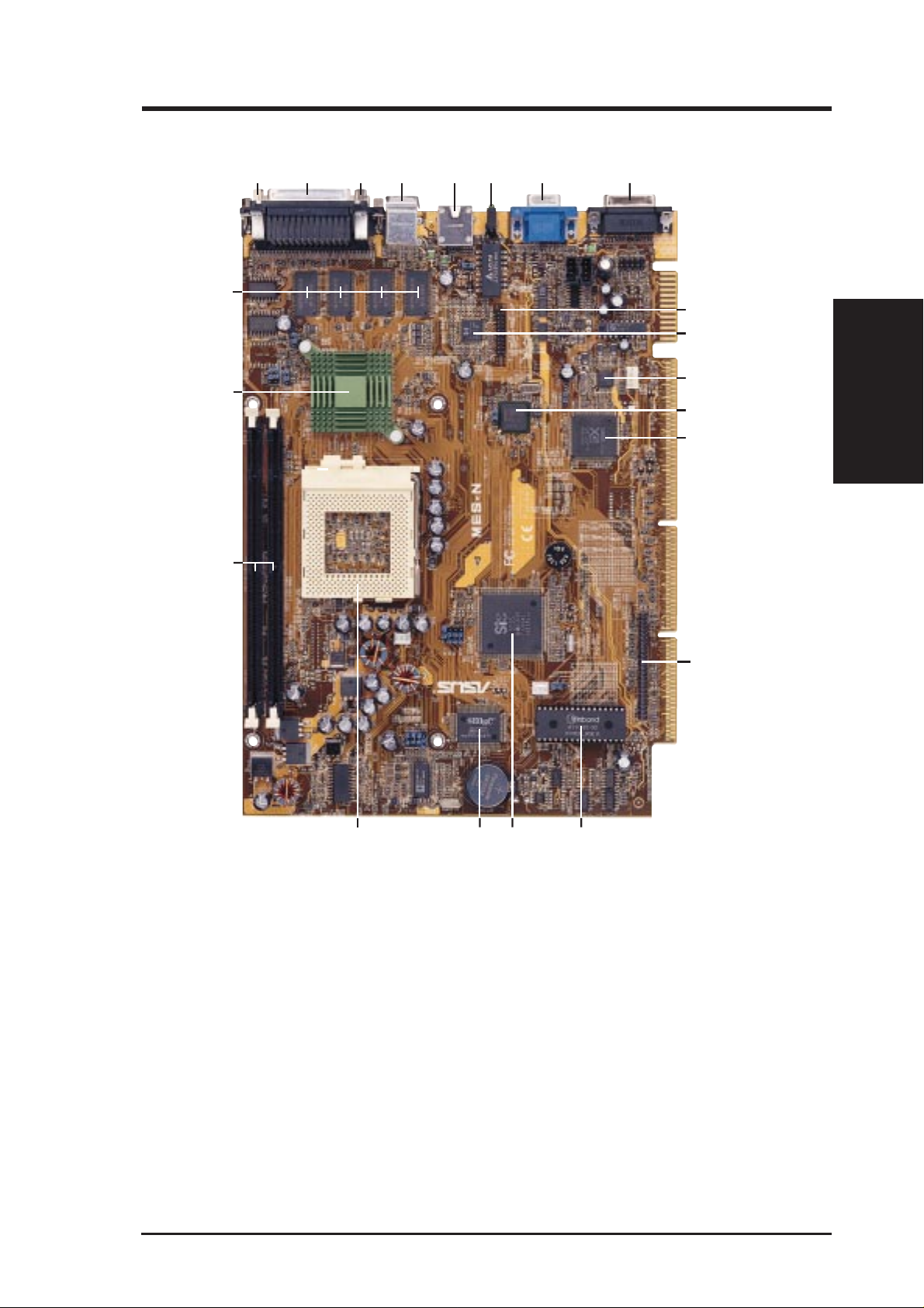
2.2 Motherboard Parts
321 456 7 8
21
9
10
T: T op
B: Bottom
20
19
18 17 16
15
11
12
13
14
2. FEATURES
Motherboard Parts
COM1 Connector (B)
1
Parallel Connector (
2
COM2 Connector (
3
4
PS/2 Mouse (
RJ-45 Connector
5
6
LAN LED
VGA Connector
7
Joystick/MIDI Connector
8
9
LCD Header (w/ LCD Chip onboard)
LCD Chip (optional)
10
11
Audio CODEC (optional)
T)/Keyboard (B) Connector
T)
B)
ASUS MES-N User’s Manual 11
12
LAN Controller Chip (optional)
13
Y amaha Audio Chip (on audio model only)
14
Slim CD-ROM Connector
15
Programmable Flash EEPROM
16
SiS South Bridge
with Integrated Hardware Monitoring
17
Multi-I/O Chip
18
CPU ZIF Socket 370
19
DIMM Sockets
20
SiS Chipset with Heatsink
21
Optional VGA Memory (up to 8MB)
3. HARDWARE SETUP
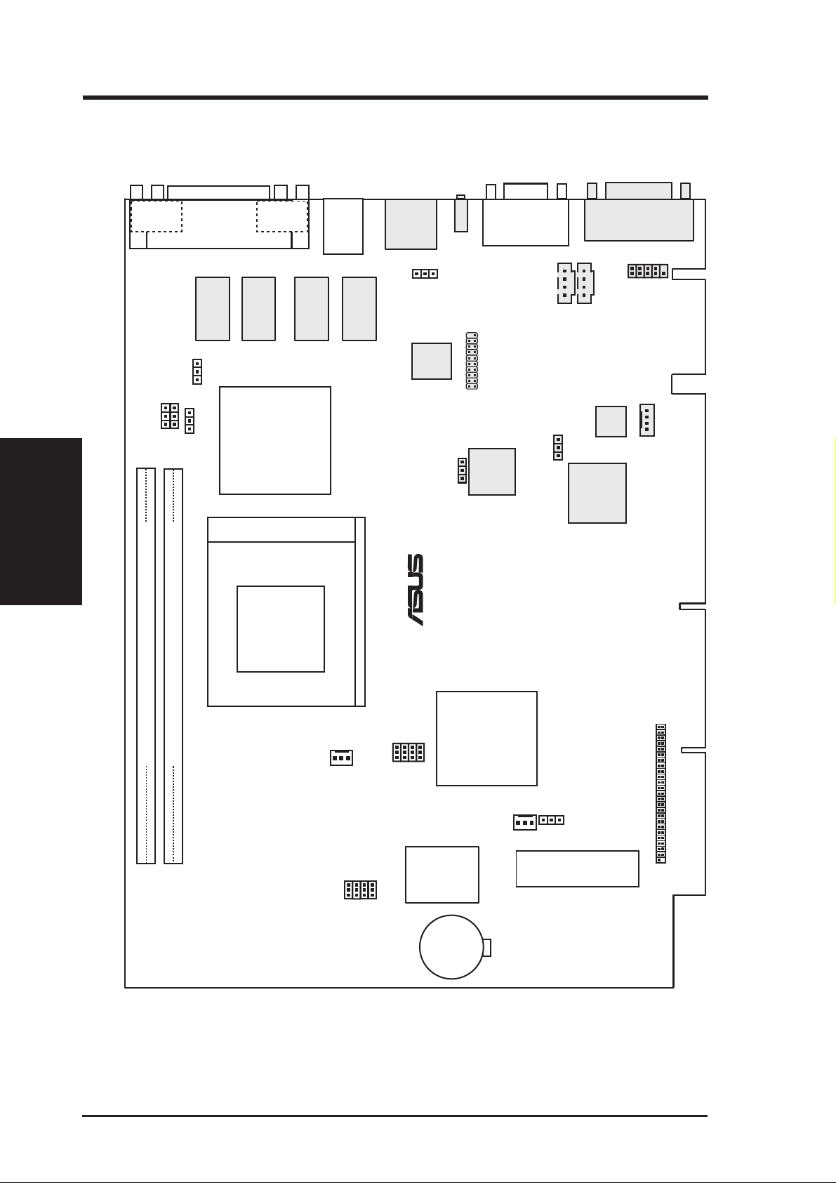
3.1 Motherboard Layout
COM 1
VIRQ
Motherboard Layout
3. H/W SETUP
Parallel
Port
Connector
2 MB
SDRAM
PCTS
VEN_DIS
SiS 620
SCTS
AGP 2X VGA)
Socket 370
COM 2
2 MB
SDRAM
Chipset
(Integrated
PS/2
TOP:
KB
MOUSE
BOTTOM:
MS
KEYBOARD
2 MB
SDRAM
2 MB
SDRAM
RJ-45
KB_UP
LCD
Encoder
®
LAN
VGA
LAN_LED
LCDHD
Intel Fast
Ethernet
Joystick/MIDI
GAME
JACK_CON
CD_IN AUX_IN
Audio
AUDIO_EN
Codec
Yamaha
Audio
Chipset
MODEM
MES-N
SiS5595
with Hardware
BF3
BF2
BF1
BF0
DIMM Socket 2 (64/72-bit, 168-pin module)
DIMM Socket 1 (64/72-bit, 168-pin module)
CPU_FAN
FREQ
MULT
32
10
Row
FS0
FS1
FS2
FS3
Super I/O
BUS
FREQ
Grayed items are optional at the time of purchase.
Monitor
Keyboard
Controller
CR2032 3V
Lithium Cell
(CMOS Power)
CHASIS_FAN
&
CL_RTC
Flash EEPROM
(Programmable BIOS)
CDROM Connector
12 ASUS MES-N User’s Manual

3. HARDWARE SETUP
Motherboard Settings
1) KB_UP p.18 Keyboard Wake Up Setting (Enable/Disable)
2) VEN_DIS p.18 Onboard VGA Setting (Enable/Disable)
3) VIRQ p.19 VGA IRQ Setting (Enable/Disable)
4) AUDIOEN p.19 Onboard Audio Setting (Enable/Disable)
5) LAN p.20 Onboard LAN Setting (Enable/Disable)
6) PCTS p.20 Primary Cable Type Status (80 pin/40 pin)
7) SCTS p.21 Secondary Cable Type Status (80 pin/40 pin)
8) FS0, FS1, FS2, FS3 p.22 CPU External Frequency Setting
9) BF0, BF1, BF2, BF3 p.23 CPU Core:External Frequency Multiple Setting
10) CL_RTC p.53 CMOS RTC RAM Setting
Sockets
1) DIMM1, DIMM2 p.24 168-Pin DIMM Memory Support
2) Socket 370 p.26 Central Processing Unit (CPU) Socket
Back Panel Connectors
1) PARALLEL p.29 Parallel Port Connector (25-pin female)
2) COM1/COM2 p.29 Serial Port Connector (Two 9-pin male)
3) PS2KBMS p.30 PS/2 Mouse Port Connector (6-pin female)
4) PS2KBMS p.30 PS/2 Keyboard Port Connector (6-pin female)
5) RJ-45 p.30 Fast-Ethernet Port Connector (optional)
6) LAN_LED p.30 LAN Diagnostic LEDs
7) VGA p.31 Monitor (VGA) Output Connector (15-pin female)
8) GAME p.31 Joystick/MIDI Connector (15-pin female) (optional)
Midboard Connectors
1) CHASIS_, CPU_FAN p.32 Chassis & CPU Fan Connectors (Two 3 pins)
2) CDROM p.32 CDROM Connector (50-1 pins)
3) CD_IN/AUX_IN/MODEM_IN p.33 Internal Audio Connectors (Four 4 pins)
4) JACK_CON p.33 Audio Jack Connector (10-1 pins)
5) LCDHD p.34 LCD Output Header (20-1 pins)
3. H/W SETUP
Motherboard Contents
ASUS MES-N User’s Manual 13
3. HARDWARE SETUP
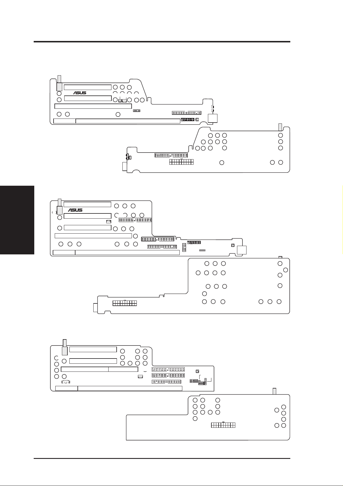
3.2 Riser Card Layout
3.2.1 NLX-R
PCI2
®
CHASS_DET
NLX_EXT
NLX-R
PCI1
ISA
NLX-R Riser Card Front
LAN LED
WOL_CON
HEAD_SPK
NLX_SLOT
FLOPPY
FCON
MIC-CON
USB
Riser Card Parts & Layout
3. H/W SETUP
3.2.2 B9-N
CHASS_DET
NLX_EXT
B9-N Riser Card Front
PCI3
®
PCI2
PCI1
ISA
B9-N
WAKEUP
IR
CIR
NLX-R Riser Card Back
IDEA
IDEB
FLOPPY
NLX_SLOT
ATXPWR
POWER
IDE1
LED_CTRL
IR
HEAD_SPK
JP-2K
USB1
B9-N Riser Card Back
3.2.3 Yeong-Yang
PCI1
SWITCH
YEONG-YANG
CDIN
NLX_EXT
Yeong-Yang Riser Card Front
14 ASUS MES-N User’s Manual
SLOT1
PCI2
SLOT1A
WOL_CON
RISER
IDE2
IDE1
FLOPPY
Yeong-Yang Riser Card Back
MIC
USB
IR
Panel
PWRLED
HDD_LED
RESET
PWRSW
SPKR
Power

3. HARDWARE SETUP
Expansion Slots
1) ISA (NLX-R) p.27 16-bit ISA Bus Expansion Slot
ISA (B9-N) 16-bit ISA Bus Expansion Slot
SLOT1/1A (Yeong-Yang) 16-bit ISA Bus Expansion Slot
2) PCI1, PCI2 (NLX-R) p.27 32-bit PCI Bus Expansion Slots
PCI1, PCI2, PCI3 (B9-N) 32-bit PCI Bus Expansion Slots
PCI1, PCI2 (Yeong-Yang) 32-bit PCI Bus Expansion Slots
Connectors
1) LAN_LED (NLX-R) p.35 LAN Activity Connector (2 pins)
WOL_CON (NLX-R) LAN Activity Connector (3 pins)
WAKEUP (B9-N) LAN Activity Connector (3 pins)
WOL_CON (Yeong-Yang) LAN Activity Connector (3 pins)
2) MIC-CON (NLX-R) p.35 Front Panel Microphone Connector (2 pins)
JP-2K (B9-N) Front Panel Microphone Connector (2 pins)
MIC (Yeong-Yang) Front Panel Microphone Connector (2 pins)
3) POWER (NLX-R) p.36 NLX Power Supply Connector (20 pins)
ATXPWR (B9-N) NLX Power Supply Connector (20 pins)
Power (Yeong-Yang) NLX Power Supply Connector (20 pins)
4) IDE1 (NLX-R) p.36 IDE Connector (40-1 pins)
IDEA, IDEB (B9-N) IDE Connectors (40-1 pins)
IDE1, IDE2 (Yeong-Yang) IDE Connectors (40-1 pins)
5) FLOPPY (NLX-R) p.37 3.5” Floppy Disk Drive Connnector (34-1 pins)
FLOPPY (B9-N) 3.5” Floppy Disk Drive Connnector (34-1 pins)
FLOPPY (Yeong-Yang) 3.5” Floppy Disk Drive Connnector (34-1 pins)
6) USB (NLX-R) p.37 Universal Serial Bus (USB) Ports (Two 4-pin sockets)
USB1 (B9-N) Universal Serial Bus (USB) Ports (Two 4-pin sockets)
USB (Yeong-Yang) USB Module Connector (5-1 pins)
7) IR, CIR (NLX-R) p.38 IrDA-Compliant Infrared Module (Lenses)
IR (B9-N) Infrared Module Connector (10-1 pins)
IR (Yeong-Yang) Infrared Module Connector (5-1 pins)
8) CDIN (Yeong-Yang) p.39 Stereo Audio In Connector (4 pins)
9) FCON/HEAD_SPK (NLX-R) p.39 Front Panel Connector (16-1 pins)
LED_CTRL/HEAD_SPK (B9-N) Front Panel Connector (16-1 pins)
Panel (Yeong-Yang) Front Panel Connectors (13 pins)
3. H/W SETUP
Riser Card Contents
ASUS MES-N User’s Manual 15

(This page was intentionally left blank.)
16 ASUS MES-N User’s Manual

3. HARDWARE SETUP
3.3 Hardware Setup Procedure
NOTE: The following procedure assumes that you have already installed the
motherboards in an appropriate housing or case.
Before using your computer, you must complete the following steps:
1. Check Motherboard Settings
2. Install Memory Modules
3. Install the Central Processing Unit (CPU)
4. Install Expansion Cards
5. Connect Ribbon Cables, Panel Wires, and Power Supply
3.4 Motherboard Settings
This section explains in detail how to change your motherboard’s function settings
through the use of switches and/or jumpers.
W ARNING! Computer motherboards and expansion cards contain very delicate
Integrated Circuit (IC) chips. To protect them against damage from static electricity, you should follow some precautions whenever you work on your computer.
1. Unplug your computer when working on the inside.
2. Use a grounded wrist strap before handling computer components. If you do
not have one, touch both of your hands to a safely grounded object or to a metal
object, such as the power supply case.
3. Hold components by the edges and try not to touch the IC chips, leads or connectors, or other components.
4. Place components on a grounded antistatic pad or on the bag that came with the
component whenever the components are separated from the system.
3. H/W SETUP
Motherboard Settings
ASUS MES-N User’s Manual 17
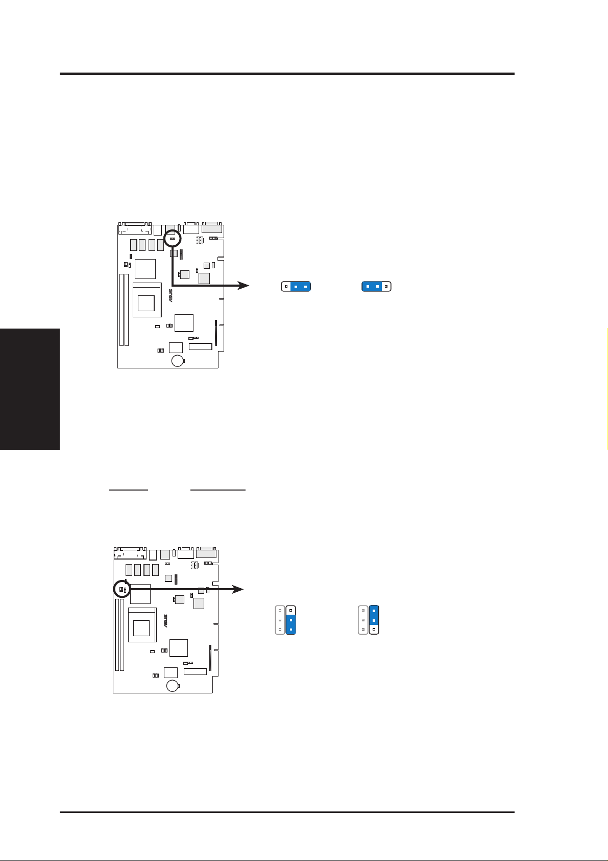
1) Keyboard Power Up Setting (3-pin KB_UP)
This allows you to disable or enable the keyboard power up function. Set this
jumper to Enable if you wish to use your keyboard (by pressing any key or the
spacebar depending on your motherboard) to power up your computer. This
feature requires an NLX power supply that can supply at least 300mA on the
+5VSB lead. The default is set to Disable because not all computers have the
appropriate NLX power supply. Your computer will not power ON if you set
this to Enable and do not have the appropriate NLX power supply.
Motherboard Settings
3. H/W SETUP
3. HARDWARE SETUP
TOP:
MOUSE
BOTTOM:
KEYBOARD
KB_UP
®
MES-N
321
Disable
(Default)
321
Enable
MES-N Keyboard Wake Up
2) Onboard VGA Setting (VEN_DIS)
The onboard AGP VGA may be enabled or disabled using this switch. Disable
the onboard VGA if you are using a VGA card on the expansion slot.
Setting VEN_DIS
Enable [2-3] (default)
Disable [1-2]
TOP:
MOUSE
BOTTOM:
KEYBOARD
VEN_DIS
®
MES-N
3
2
1
Disable
3
2
1
Enable
(Default)
MES-N Onboard VGA Setting
18 ASUS MES-N User’s Manual
3. HARDWARE SETUP
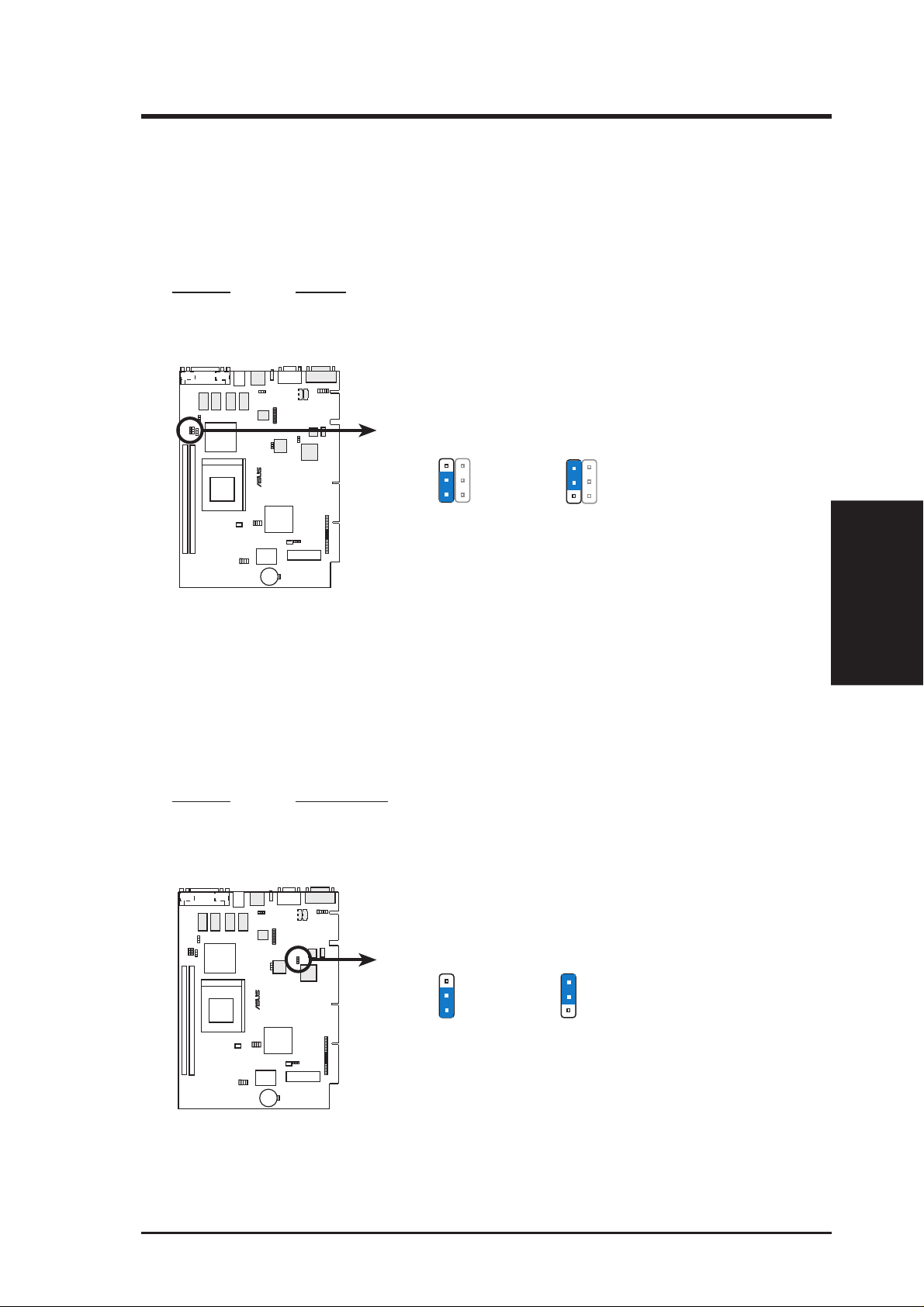
3) VGA IRQ Setting (VIRQ)
VIRQ allows you to set the VGA interrupt method. Some TV tuners or MPEG
cards may require the interrupt to be assigned by the onboard chipset, in which
case VIRQ must be enabled (default setting). The default enables the chipset’s
internal interrupt routing.
Setting VIRQ
Enable [2-3] (default)
Disable [1-2]
TOP:
MOUSE
BOTTOM:
KEYBOARD
VIRQ
®
MES-N
3
2
1
Disable
3
2
1
Enable
(Default)
MES-N Onboard VGA IRQ Setting
4) Onboard Audio Setting (AUDIOEN)
The onboard 32-bit PCI audio may be enabled or disabled using this jumper.
Disable the onboard audio if you are using an audio card on the expansion slot.
NOTE: This setting is available only on motherboards with the onboard audio
option.
Setting AUDIOEN
Enable [2-3] (default)
Disable [1-2]
TOP:
MOUSE
BOTTOM:
KEYBOARD
3. H/W SETUP
Motherboard Settings
®
MES-N
3
2
1
Disable
MES-N Onboard Audio Setting
ASUS MES-N User’s Manual 19
AUDIO_EN
3
2
1
Enable
(Default)
3. HARDWARE SETUP
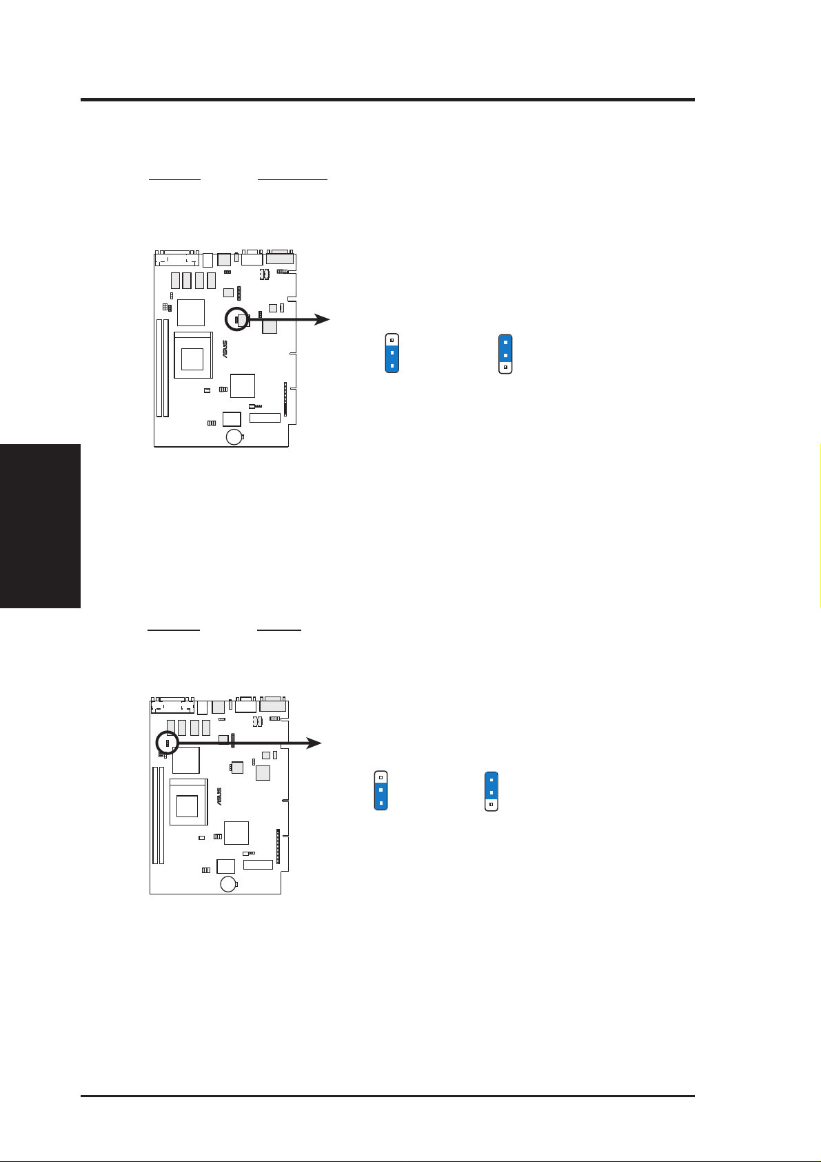
5) Onboard LAN Setting (LAN_EN) available on LAN model only
The onboard LAN may be enabled or disabled by this jumper.
Setting LAN_EN
Enable [1-2] (default)
Disable [2-3]
TOP:
MOUSE
BOTTOM:
KEYBOARD
LAN
Motherboard Settings
3. H/W SETUP
MES-N Onboard LAN Setting
6) Primary Cable Type Status (PCTS)
Setting this jumper to 80-pin will allow an UltraDMA/66 IDE device that is
connected to the primary IDE connector with a 40-pin 80-conductor IDE cable
to handle transfer rates up to 66MB/s.
Setting PCTS
40 pin [2-3] (default)
80 pin [1-2]
®
MES-N
TOP:
MOUSE
BOTTOM:
KEYBOARD
Disable
3
2
1
3
2
1
Enable
(Default)
PCTS
®
MES-N
80-pin Cable
3
2
1
3
2
1
40-pin Cable
(Default)
MES-N Primary Cable Type Status
20 ASUS MES-N User’s Manual
3. HARDWARE SETUP
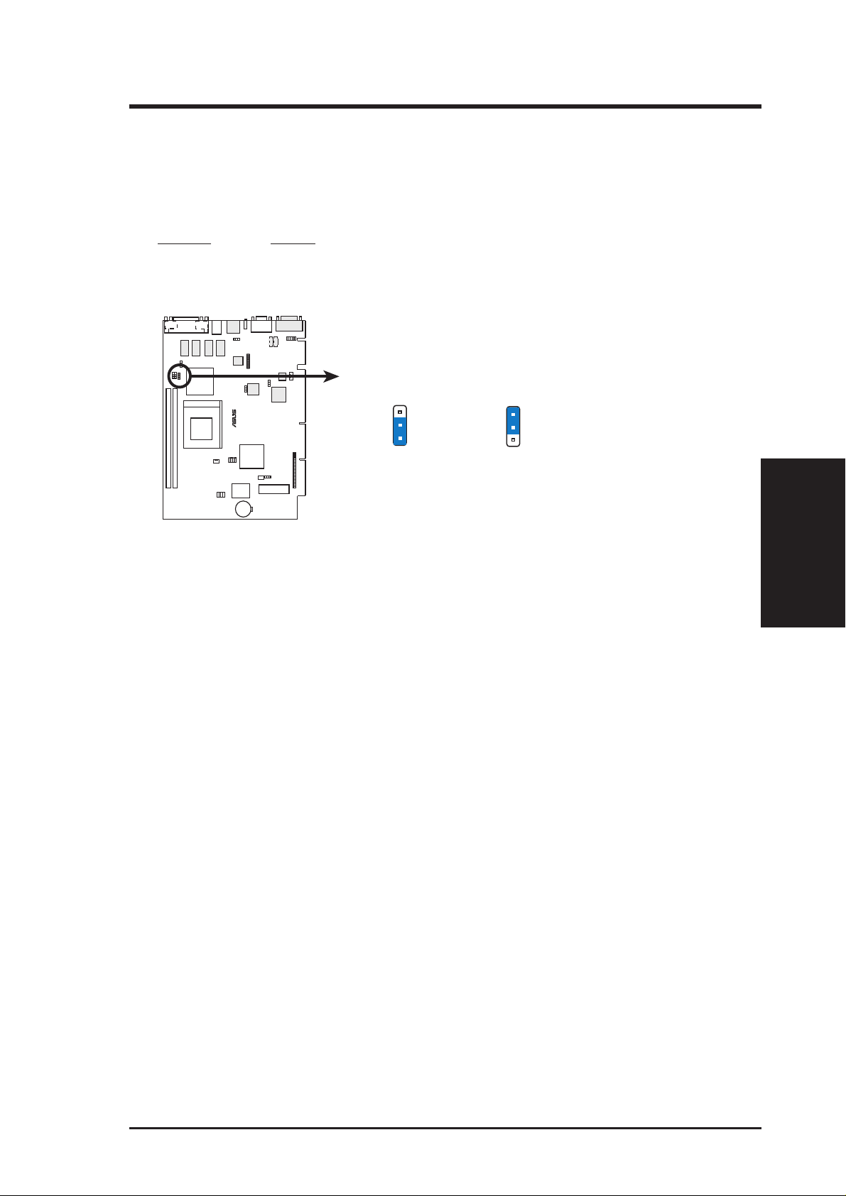
7) Secondary Cable Type Status (SCTS)
Setting this jumper to 80-pin will allow an UltraDMA/66 IDE device that is
connected to the secondary IDE connector with a 40-pin 80-conductor IDE cable
to handle transfer rates up to 66MB/s.
Setting SCTS
40 pin [2-3] (default)
80 pin [1-2]
TOP:
MOUSE
BOTTOM:
KEYBOARD
SCTS
®
MES-N
80-pin Cable
3
2
1
MES-N Secondary Cable Type Status
3
2
1
40-pin Cable
(Default)
3. H/W SETUP
Motherboard Settings
ASUS MES-N User’s Manual 21
3. HARDWARE SETUP
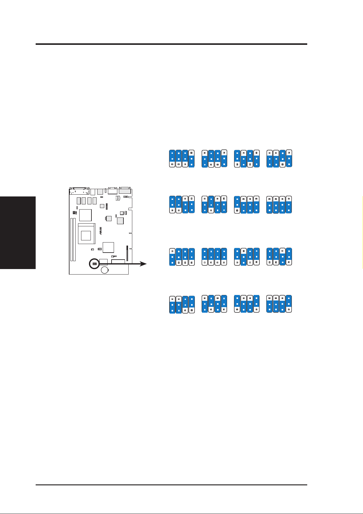
8) CPU External Frequency Setting (FS0, FS1, FS2, FS3)
This option tells the clock generator what frequency to send to the CPU, DRAM,
and the AGPset. This allows the selection of the CPU’ s External frequency . The
CPU external frequency multiplied by the Frequency Multiple equals the CPU’ s
Internal frequency (the advertised CPU speed). NOTE: You may set the memory
speed independently from the CPU external frequency. Depending on your
memory type PC66 (66MHz) or PC100 (100MHz), select the appropriate “RAM”
speed along with the appropriate “CPU” speed.
Motherboard Settings
3. H/W SETUP
MES-N CPU External
Frequency Setting
Sync
HOST
SDRAM
PCI
TOP:
MOUSE
BOTTOM:
KEYBOARD
HOST
®
MES-N
SDRAM
PCI
Async
HOST
SDRAM
PCI
HOST
SDRAM
PCI
3
2
1
66.6MHZ
→
→
66.6MHZ
→
33.0MHZ
3
2
1
100.0MHZ
→
→
100.0MHZ
→
3
2
1
→
66.7MHZ
→
100.0MHZ
→
33.3MHZ
3
2
1
100.0MHZ
→
→
→
FS1
FS2
FS0
FS1
FS2
FS0
33.3MHZ
FS1
FS2
FS0
FS1
FS2
FS0
66.7MHZ
33.3MHZ
FS3
FS3
FS3
FS3
3
2
1
3
2
1
3
2
1
3
2
1
FS1
FS2
FS0
75.0MHZ
75.0MHZ
30.0MHZ
FS1
FS2
FS0
112MHZ
112MHZ
37.3MHZ
FS1
FS2
FS0
90MHZ
90MHZ
30MHZ
FS1
FS2
FS0
112.0MHZ
74.7MHZ
37.3MHZ
FS3
3
2
1
FS3
3
2
1
FS3
3
2
1
FS3
3
2
1
FS1
FS2
FS0
83.3MHZ
83.3MHZ
33.0MHZ
FS1
FS2
FS0
124MHZ
124MHZ
31MHZ
FS1
FS2
FS0
95.0MHZ
63.3MHZ
31.7MHZ
FS1
FS2
FS0
124.0MHZ
82.7MHZ
31.0MHZ
FS3
3
2
1
FS3
3
2
1
FS3
3
2
1
FS3
3
2
1
FS1
FS2
FS0
95.0MHZ
95.0MHZ
31.7MHZ
FS1
FS2
FS0
133MHZ
133MHZ
33MHZ
FS1
FS2
FS0
100.0MHZ
75.0MHZ
30.0MHZ
FS1
FS2
FS0
133.0MHZ
88.9MHZ
33.0MHZ
FS3
FS3
FS3
FS3
22 ASUS MES-N User’s Manual
3. HARDWARE SETUP
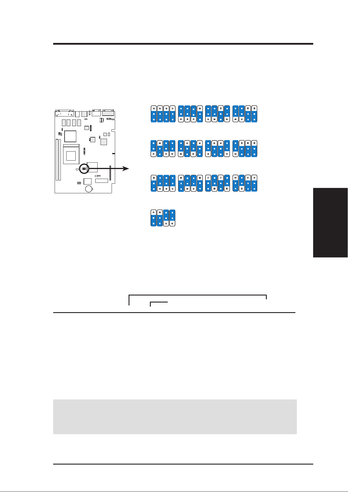
9) CPU Core:External Frequency Multiple Setting (BF0, BF1, BF2, BF3)
This option sets the frequency multiple between the Internal frequency of the
CPU and the CPU’ s External frequency . These must be set in conjunction with the
CPU External frequency.
BF2
BF1
TOP:
MOUSE
BOTTOM:
KEYBOARD
®
MES-N
MES-N CPU Core:Bus
Frequency Multiple
Selection
BF2
BF1
BF3
3
2
1
2.0x(2/1)
BF3
3
2
1
4.0x(4/1) 4.5x(9/2) 5.0x(5/1)
BF3
3
2
1
6.0x(6/1)
BF3
3
2
1
8.0x(8/1)
BF2
BF2
BF2
BF1
BF1
BF1
BF0
BF3
2.5x(5/2)
BF0
BF3
BF0
BF3
6.5x(13/2)
BF0
BF2
BF2
BF2
BF1
BF1
BF1
BF0
BF0
BF0
BF3
BF3
BF3
BF2
BF2
BF1
BF1
BF0
BF3
3.5x(7/2)3.0x(3/1)
BF3
BF0
5.5x(11/2)
BF0
BF3
7.5x(15/2)7.0x(7/1)
BF2
BF2
BF2
BF1
BF1
BF1
BF0
BF0
BF0
Set the jumpers by the Internal speed of your processor as follows:
(CPU External Frequency) (Frequency Multiple)
Intel CPU Model Speed Mult Freq. FS0 FS1 FS2 FS3 BF3 BF2 BF1 BF0
Celeron (PPGA) 500MHz 7.5x 66MHz [1-2] [2-3] [2-3] [2-3] [1-2] [2-3] [1-2] [1-2]
Celeron (PPGA) 466MHz 7.0x 66MHz [1-2] [2-3] [2-3] [2-3] [1-2] [2-3] [1-2] [2-3]
Celeron (PPGA) 433MHz 6.5x 66MHz [1-2] [2-3] [2-3] [2-3] [1-2] [2-3] [2-3] [1-2]
Celeron (PPGA) 400MHz 6.0x 66MHz [1-2] [2-3] [2-3] [2-3] [1-2] [2-3] [2-3] [2-3]
Celeron (PPGA) 366MHz 5.5x 66MHz [1-2] [2-3] [2-3] [2-3] [2-3] [1-2] [1-2] [1-2]
Celeron (PPGA) 333MHz 5.0x 66MHz [1-2] [2-3] [2-3] [2-3] [2-3] [1-2] [1-2] [2-3]
Celeron (PPGA) 300MHz 4.5x 66MHz [1-2] [2-3] [2-3] [2-3] [2-3] [1-2] [2-3] [1-2]
W ARNING! Frequencies above 100MHz exceed the specifications for the on-
board chipset and are not guaranteed to be stable. PCI frequencies above 33MHz
exceed the specifications for PCI cards and are not guaranteed to be stable.
3. H/W SETUP
Motherboard Settings
For updated processor settings, visit the ASUS web site (see ASUS CONTACT INFORMATION)
ASUS MES-N User’s Manual 23
3.5 System Memory (DIMM)
NOTE: No hardware or BIOS setup is required after adding or removing memory.
This motherboard uses only Dual Inline Memory Modules (DIMMs). Sockets are
available for 3.3Volt (power level) unbuffered Synchronous Dynamic Random Ac-
cess Memory (SDRAM).
The SiS chipset does not support ECC. However, ECC memory modules may still
be used, but the ECC function will not be available.
Memory speed setup is recommended through SDRAM Configuration in 4.4.1
Chip Configuration.
Install memory in any combination as follows:
DIMM Location 168-pin DIMM Total Memory
Socket 1 (Rows 0&1) SDRAM 8, 16, 32, 64, 128, 256MB x1
Socket 2 (Rows 2&3) SDRAM 8, 16, 32, 64, 128, 256MB x1
System Memory
3. H/W SETUP
3. HARDWARE SETUP
Total System Memory (Max 512MB) =
3.5.1 General DIMM Notes
• VGA shared memory with one DIMM: When using only one DIMM as shared
memory for the onboard VGA, it must be inserted into Socket 1, leaving Socket
2 empty.
• At the time this User’s Manual was written, 256MB DIMMs are either available
as registered memory or 128Mbit DIMMs.
• For the system CPU bus to operate at 100MHz, use only PC100-compliant
DIMMs. When this motherboard operates at 100MHz, most system will not
even boot if non-compliant modules are used because of the strict timing issues
involved under this speed. If your DIMMs are not PC100-compliant, set the
CPU external frequency to 66MHz RAM to ensure system stability. NOTE: If
your motherboard supports asynchronous mode, set the memory clock frequency
to 66MHz.
• ASUS motherboards support SPD (Serial Presence Detect) DIMMs. This is the
memory of choice for best performance vs. stability.
• SDRAM chips are generally thinner with higher pin density than EDO (Extended Data Output) chips.
• BIOS shows SDRAM memory on bootup screen.
24 ASUS MES-N User’s Manual
3. HARDWARE SETUP
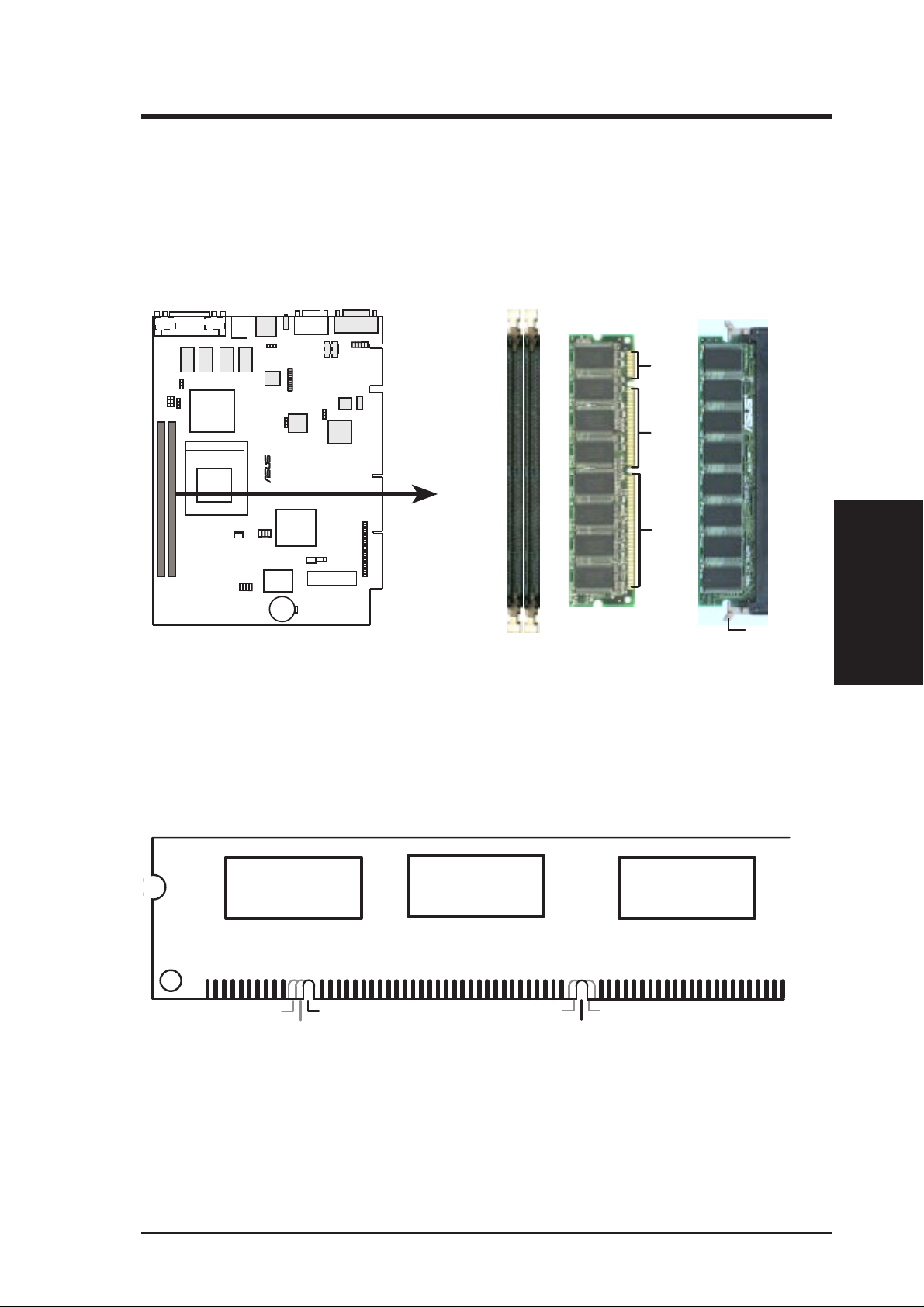
3.5.2 DIMM Memory Installation
Insert the module(s) as shown. Because the number of pins are different on either
side of the breaks, the module will only fit in the orientation as shown. DIMM
modules are longer and have different pin contact on each side and therefore have a
higher pin density. SIMM modules have the same pin contact on both sides.
TOP:
MOUSE
BOTTOM:
KEYBOARD
20 Pins
®
60 Pins
MES-N
88 Pins
Lock
MES-N 168-pin DIMM Memory Sockets
The DIMMs must be 3.3V Unbuffered for this motherboard. T o determine the DIMM
type, check the notches on the DIMMs (see figure below).
168-Pin DIMM Notch Key Definitions (3.3V)
3. H/W SETUP
System Memory
DRAM Key Position
RFU
Buffered
Unbuffered
Voltage Key Position
5.0V
Reserved
3.3V
The notches on the DIMM module will shift between left, center, or right to identify
the type and also to prevent the wrong type from being inserted into the DIMM slot
on the motherboard. You must ask your retailer the correct DIMM type before purchasing. This motherboard supports four clock signals.
ASUS MES-N User’s Manual 25
3. H/W SETUP
CPU
3. HARDWARE SETUP
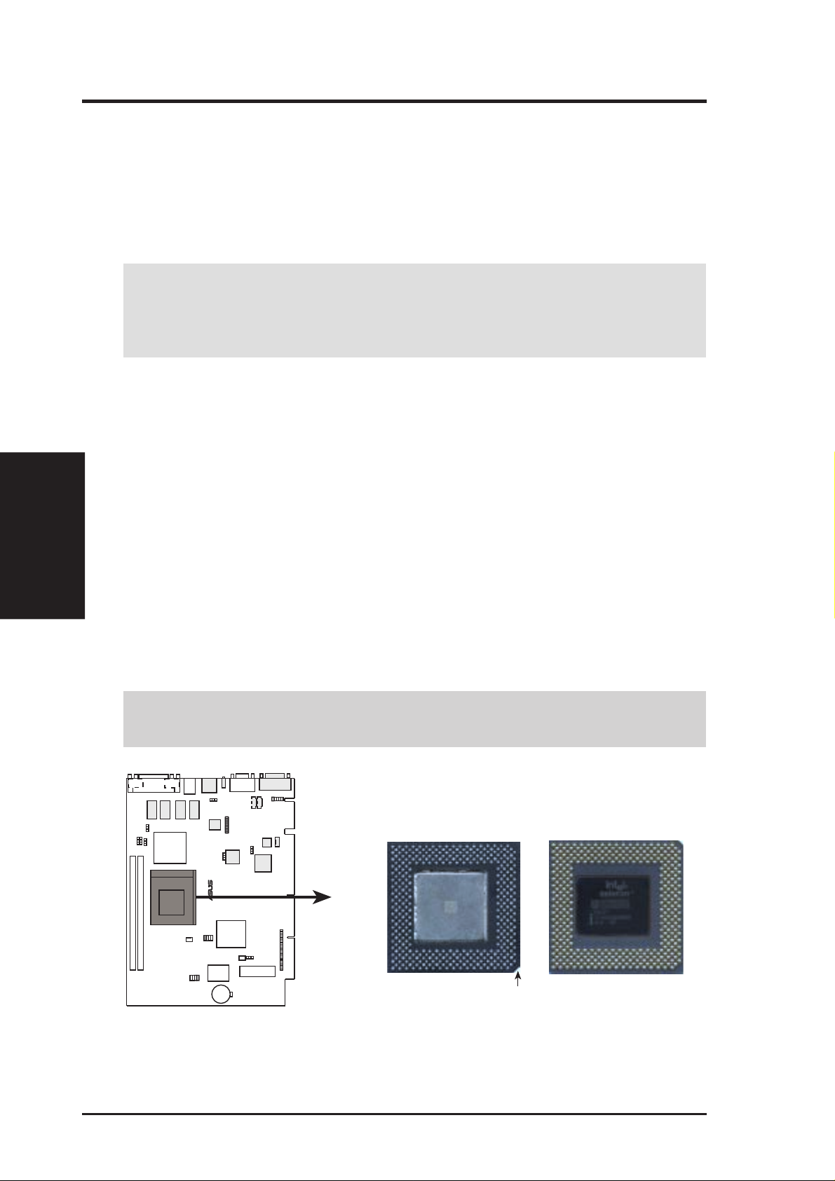
3.6 Central Processing Unit (CPU)
This motherboard provides a ZIF (Zero Insertion Force) Socket 370. The CPU for
your motherboard should have a fan attached to it to prevent overheating. If this is
not the case, then purchase a fan before you turn on your system.
WARNING! Be sure that there is sufficient air circulation across the processor’s
heatsink by regularly checking that your CPU fan is working. W ithout sufficient
circulation, the processor could overheat and damage both the processor and the
motherboard. You may install an auxiliary fan, if necessary.
To install a CPU, first turn off your system and remove its cover. Locate the ZIF
socket and open it by first pulling the lever sideways away from the socket then
upwards to a 90-degree angle. Insert the CPU with the correct orientation as shown.
The notched corner should point toward the end of the lever . Because the CPU has
a corner pin for two of the four corners, the CPU will only fit in the orientation as
shown. The picture below is for reference only; you should have a CPU fan that
covers the face of the CPU. With the added weight of the CPU fan, no force is
required to insert the CPU. Once completely inserted, push the socket’ s lever down
while holding down the CPU.
NOTE: Do not forget to set the correct Bus Frequency and Multiple for your Socket
370 processor or else your system may start. Socket 370 processors provide internal
thermal sensing so that a socket mounted thermal resistor is not needed.
CAUTION! Be careful not to scrape the motherboard when mounting a clamp-
style processor fan or else damage may occur to the motherboard.
TOP:
MOUSE
BOTTOM:
KEYBOARD
Socket 370 CPU (Top) Socket 370 CPU (Bottom)
®
MES-N
Notch
MES-N Socket 370
26 ASUS MES-N User’s Manual

3. HARDWARE SETUP
3.7 Expansion Cards
WARNING! Make sure that you unplug your power supply when adding or
removing expansion cards or other system components. Failure to do so may
cause severe damage to both your motherboard and expansion cards.
3.7.1 Expansion Card Installation Procedure
1. Read the documentation for your expansion card and make any necessary hardware settings for your expansion card, such as jumpers or switches.
2. Remove your computer system’s cover and the bracket plate on the slot you
intend to use. Keep the bracket for possible future use.
3. Carefully align the card’s connectors and press firmly.
4. Secure the card on the slot with the screw you removed above.
5. Replace the computer system’s cover.
6. Set up the BIOS if necessary
(such as IRQ xx Used By ISA: Yes)
7. Install the necessary software drivers for your expansion card.
3.7.2 Assigning IRQs for Expansion Cards
Some expansion cards need to use an IRQ to operate. Generally, an IRQ must be
exclusively assigned to one use. In a standard design, there are 16 IRQs available
but most of them are already in use, leaving 6 IRQs free for expansion cards. If your
motherboard has PCI audio onboard, an extra IRQ will be used, leaving 5 IRQs
free. If your motherboard has ISA audio onboard, an extra 3 IRQs will be used,
leaving 3 IRQs free.
Both ISA and PCI expansion cards may require IRQs. System IRQs are available to
cards installed in the ISA expansion bus first, then any remaining IRQs are available
to PCI cards. Currently, there are two types of ISA cards.
The original ISA expansion card design, now referred to as “Legacy” ISA cards,
requires that you configure the card’s jumpers manually and then install it in any
available slot on the ISA bus. To see a map of your used and free IRQs in Windows
98, the Control Panel icon in My Computer, contains a System icon, which gives
you a Device Manager tab. Double-clicking on a specific hardware device gives you
the Resources tab which shows the Interrupt number and address. Make sure that no
two devices use the same IRQ or your computer will experience problems when
those two devices are in use at the same time.
3. H/W SETUP
Expansion Cards
ASUS MES-N User’s Manual 27

To simplify this process, this motherboard complies with the Plug and Play (PnP)
specification, which was developed to allow automatic system configuration whenever a PnP-compliant card is added to the system. For PnP cards, IRQs are assigned
automatically from those available.
If the system has both Legacy and PnP ISA cards installed, IRQs are
assigned to PnP cards from those not used by Legacy cards. The PCI and PnP configuration of the BIOS setup utility can be used to indicate which IRQs are being
used by Legacy cards. For older Legacy cards that do not work with the BIOS, you
can contact your vendor for an ISA Configuration Utility.
An IRQ number is automatically assigned to PCI expansion cards after those used
by Legacy and PnP ISA cards. In the PCI bus design, the BIOS automatically assigns an IRQ to a PCI slot that has a card in it that requires an IRQ. To install a PCI
card, you need to set something called the INT (interrupt) assignment. Since all the
PCI slots on this motherboard use an INTA #, be sure that the jumpers on your PCI
cards are set to INT A.
Expansion Cards
3. H/W SETUP
3. HARDWARE SETUP
3.7.3 Assigning DMA Channels for ISA Cards
Some ISA cards, both legacy and PnP, may also need to use a DMA (Direct Memory
Access) channel. DMA assignments for this motherboard are handled the same way
as the IRQ assignment process described earlier . T o select a DMA channel, see PCI/
PNP ISA DMA Resour ce Exclusion in 4.4.3 PCI Configuration. NOTE: The onboard audio by default uses DMA1.
IMPORTANT: To avoid conflicts, reserve the necessary IRQs and DMAs for
legacy ISA cards (see PCI/PNP ISA IRQ Resource Exclusion and PCI/PNP
DMA IRQ Resource Exclusion in 4.4.3 PCI Configuration). Choose Ye s in
IRQ xx Used By ISA and DMA x Used By ISA for those IRQs and DMAs you
want to reserve).
28 ASUS MES-N User’s Manual
3. HARDWARE SETUP
3.8 External Connectors
WARNING! Some pins are used for connectors or power sources. These are
clearly distinguished from jumpers in 3.1 Motherboard Layout. Placing jumper
caps over these connector pins will cause damage to your motherboard.
IMPORTANT: Ribbon cables should always be connected with the red stripe to
Pin 1 on the connectors. Pin 1 is usually on the side closest to the power connector on hard drives and CD-ROM drives, but may be on the opposite side on
floppy disk drives. Check the connectors before installation because there may
be exceptions. IDE ribbon cables must be less than 46 cm (18 in.), with the
second drive connector no more than 15 cm (6 in.) from the first connector.
3.8.1 Back Panel Connectors
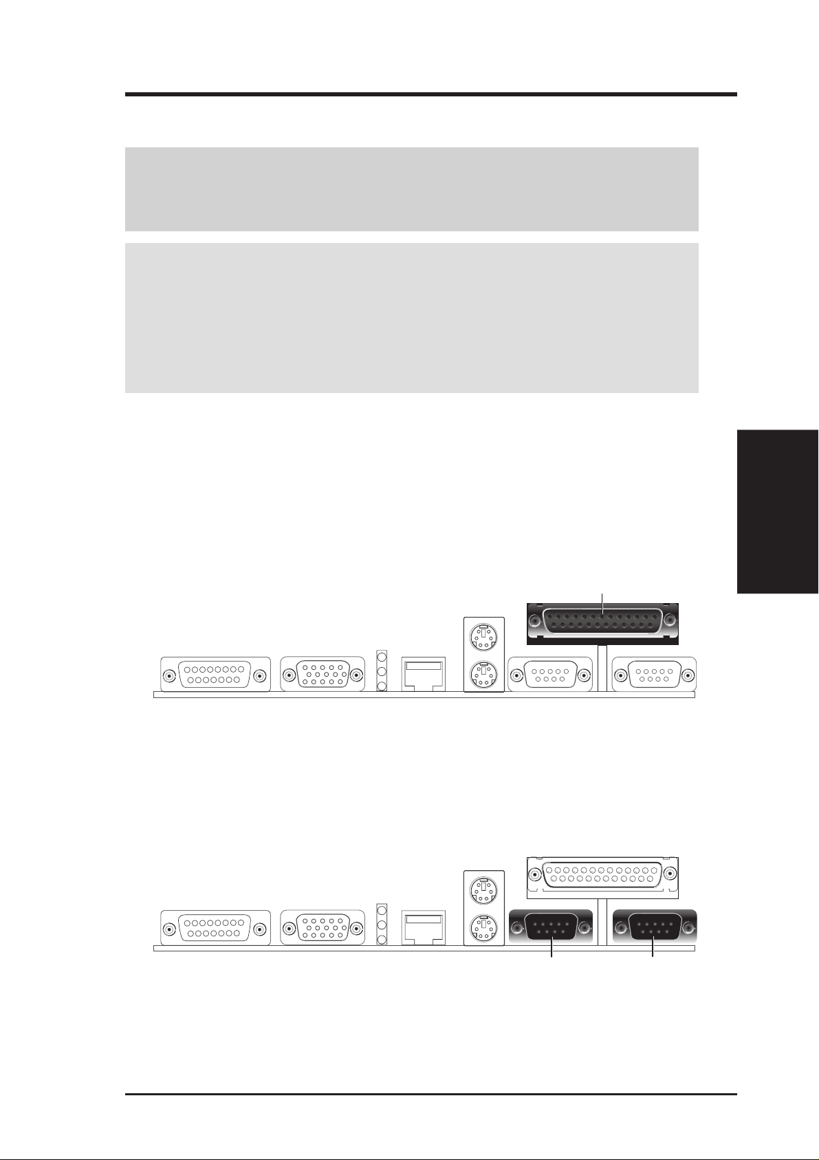
1) Parallel Connector (25-pin PRINTER)
You can enable the parallel port and choose the IRQ through Onboard Parallel
Port (see 4.4.2 I/O Device Configuration). NOTE: Serial printers must be
connected to the serial port.
Parallel Port (25-pin female)
2) Serial Port Connectors (Two 9-pin COM1 and COM2)
The two serial ports can be used for pointing devices or other serial devices. See
Onboard Serial Port 1 and Onboard Serial Port 2 in 4.2.2 I/O Device Con-
figuration for settings.
Connectors
3. H/W SETUP
COM 2 COM 1
Serial Ports (9-pin male)
ASUS MES-N User’s Manual 29
3. H/W SETUP
Connectors
3. HARDWARE SETUP
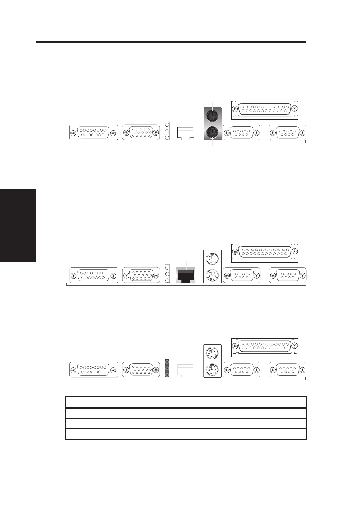
3) PS/2 Mouse Connector
The system will direct IRQ12 to the PS/2 mouse if one is detected. If not detected, expansion cards can use IRQ12. See PS/2 Mouse Function Control in
4.4 Advanced Menu.
PS/2 Mouse (6-pin female)
PS/2 Keyboard (6-pin female)
4) PS/2 Keyboard Connector (6-pin PS2KBMS)
This connector is for a standard keyboard using a PS/2 plug (mini DIN). This
connector will not allow standard AT size (large DIN) keyboard plugs. You
may use a DIN to mini DIN adapter on standard AT keyboards.
5) Fast-Ethernet Port Connector (RJ-45)
The RJ-45 connector is optional at the time of purchase. This connector allows the
motherboard to connect to a Local Area Network (LAN) through a network hub.
RJ-45
6) LAN Diagnostic LEDs (LAN_LED)
These diagnostic LEDs help indicate if there is a problem with the network
connector, cable, or hub.
1
Green
2
Yellow
3
Green
LED on LED off
1 Speed 10Mbps 100Mbps
2 Activity No data Data transfer
3 Link Bad connection Good connection
30 ASUS MES-N User’s Manual
 Loading...