

Page 1

Copyright Information
No part of this manual, including the products and software described in it, may be reproduced, transmitted, transcribed, stored in a retrieval system, or translated into any language in any form or by any means, except documentation kept by the purchaser for backup purposes, without the express written permission of ASUSTeK COMPUTER INC. (“ASUS”).
ASUS PROVIDES THIS MANUAL “AS IS” WITHOUT WARRANTY OF ANY KIND, EITHER EXPRESS OR
IMPLIED, INCLUDING BUT NOT LIMITED T O THE IMPLIED WARRANTIES OR CONDITIONS OF MERCHANTABILITY OR FITNESS FOR A PARTICULAR PURPOSE. IN NO EVENT SHALL ASUS, ITS DIRECTORS, OFFICERS, EMPLOYEES OR AGENTS BE LIABLE FOR ANY INDIRECT , SPECIAL, INCIDENTAL,
OR CONSEQUENTIAL DAMAGES (INCLUDING DAMAGES FOR LOSS OF PROFITS, LOSS OF BUSINESS, LOSS OF USE OR DATA, INTERRUPTION OF BUSINESS AND THE LIKE), EVEN IF ASUS HAS
BEEN ADVISED OF THE POSSIBILITY OF SUCH DAMAGES ARISING FROM ANY DEFECT OR ERROR
IN THIS MANUAL OR PRODUCT.
Product warranty or service will not be extended if: (1) the product is repaired, modified or altered, unless such
repair, modification of alteration is authorized in writing by ASUS; or (2) the serial number of the product is defaced
or missing.
Products and corporate names appearing in this manual may or may not be registered trademarks or copyrights of
their respective companies, and are used only for identification or explanation and to the owners’ benefit, without
intent to infringe.
SPECIFICATIONS AND INFORMATION CONTAINED IN THIS MANUAL ARE FURNISHED FOR INFORMA TIONAL USE ONL Y, AND ARE SUBJECT TO CHANGE A T ANY TIME WITHOUT NOTICE, AND SHOULD
NOT BE CONSTRUED AS A COMMITMENT BY ASUS. ASUS ASSUMES NO RESPONSIBILITY OR LIABILITY FOR ANY ERRORS OR INACCURACIES THAT MAY APPEAR IN THIS MANUAL, INCLUDING
THE PRODUCTS AND SOFTWARE DESCRIBED IN IT.
Copyright © 2004 ASUSTeK COMPUTER INC. All Rights Reserved.
Limitation of Liability
Circumstances may arise where because of a default on ASUS’ part or other liability, you are entitled to recover
damages from ASUS. In each such instance, regardless of the basis on which you are entitled to claim damages from
ASUS, ASUS is liable for no more than damages for bodily injury (including death) and damage to real property and
tangible personal property; or any other actual and direct damages resulted from omission or failure of performing
legal duties under this Warranty Statement, up to the listed contract price of each product.
ASUS will only be responsible for or indemnify you for loss, damages or claims based in contract, tort or infringement under this Warranty Statement.
This limit also applies to ASUS’ suppliers and its reseller. It is the maximum for which ASUS, its suppliers, and your
reseller are collectively responsible.
UNDER NO CIRCUMSTANCES IS ASUS LIABLE FOR ANY OF THE FOLLOWING: (1) THIRD-PARTY
CLAIMS AGAINST YOU FOR DAMAGES; (2) LOSS OF, OR DAMAGE TO, YOUR RECORDS OR DAT A; OR
(3) SPECIAL, INCIDENTAL, OR INDIRECT DAMAGES OR FOR ANY ECONOMIC CONSEQUENTIAL
DAMAGES (INCLUDING LOST PROFITS OR SAVINGS), EVEN IF ASUS, ITS SUPPLIERS OR YOUR RESELLER IS INFORMED OF THEIR POSSIBILITY.
Page 2

Notebook PC
Drivers and Utilities
Product Name: Notebook PC Support CD
Manual Revision: 1 E1472
Release Date: February 2004
Page 3

Software Reference
Table of Contents
Support CD for Windows............................................................5
New Windows Installation .................................................................................................. 5
Drivers for Windows........................................................................................................... 5
Device Manager................................................................................................................. 9
VGA Driver ........................................................................................................................... 10
VGA Driver Setup............................................................................................................. 12
ASUS_WLAN .......................................................................................................................13
Wireless LAN Driver Setup .............................................................................................. 14
INTEL_Calexico ................................................................................................................... 17
PROSet Setup ................................................................................................................. 18
INTEL Calexico Setup...................................................................................................... 18
PROSet Utility ..................................................................................................................20
ATK0100 ............................................................................................................................... 23
ATK0100 Setup................................................................................................................ 24
Audio .................................................................................................................................... 24
Audio Setup .....................................................................................................................26
CPU Hotfix ........................................................................................................................... 26
CPU Hotfix Setup 1 of 2................................................................................................... 28
CPU Hotfix Setup 2 of 2................................................................................................... 28
INFupdate............................................................................................................................. 29
INFupdate Setup.............................................................................................................. 30
LAN....................................................................................................................................... 31
LAN Driver Setup ............................................................................................................. 32
Configuring your LAN....................................................................................................... 33
Modem.................................................................................................................................. 37
Modem Setup................................................................................................................... 38
Modem Configuration....................................................................................................... 38
USB2.0.................................................................................................................................. 41
USB2.0 Setup .................................................................................................................. 42
USB Usage ...................................................................................................................... 42
2
Page 4

LiveUpdate........................................................................................................................... 43
LiveUpdate Setup ............................................................................................................ 44
Using LiveUpdate............................................................................................................. 45
PC-cillin 2002....................................................................................................................... 47
Welcome to PC-cillin 2002............................................................................................... 48
Personal Firewall ............................................................................................................. 49
PC-cillin for Wireless........................................................................................................ 49
Trojan System Cleaner .................................................................................................... 49
ScriptTrap Technology ..................................................................................................... 50
Emergency Lock .............................................................................................................. 50
User Interface ..................................................................................................................50
About Intelligent Update................................................................................................... 51
New product registration method ..................................................................................... 51
About viruses ...................................................................................................................51
How viruses are created .................................................................................................. 52
Accessing the Trend Micro Virus Encyclopedia ............................................................... 52
Viewing the Trend Micro Virus list.................................................................................... 52
Contacting Technical Support .......................................................................................... 52
PC-cillin 2002 Feature Screens ....................................................................................... 54
Software Reference
Power4 Gear ........................................................................................................................ 55
Power4 Gear Setup ......................................................................................................... 56
ASUS Probe ......................................................................................................................... 61
Probe2 Setup ................................................................................................................... 62
ASUS Probe Reference ................................................................................................... 63
TouchPad ............................................................................................................................. 67
Touchpad Setup ............................................................................................................... 68
Synaptics® TouchPad Features....................................................................................... 69
Property Pages ................................................................................................................ 72
Frequently Asked Questions ............................................................................................ 79
3
Page 5

Software Reference
WinFlash .............................................................................................................................. 81
WINFLASH Setup ............................................................................................................ 82
Using WINFLASH ............................................................................................................ 83
BIOS Setup ................................................................................85
Updating your BIOS ......................................................................................................... 86
BIOS Setup Program ....................................................................................................... 86
Main ................................................................................................................................. 90
Advanced ......................................................................................................................... 91
Advanced (sub-menu)...................................................................................................... 92
Display ............................................................................................................................. 95
Security ............................................................................................................................ 96
Security (sub-menu)......................................................................................................... 98
Power............................................................................................................................... 99
Boot................................................................................................................................ 100
Boot (sub-menu) ............................................................................................................ 101
Boot................................................................................................................................ 102
Exit ................................................................................................................................. 103
4
Page 6

Support CD for Windows
The Notebook PC you purchased may or may not be preloaded with an operating system.
The support CD included with this Notebook PC provides all the necessary drivers and
utilities in order for you to use your Notebook PC with Microsoft® Windows® XP (referred
to as “Windows” in this User’s Manual).
The levels of hardware and software support may vary depending on the installed operating system. Operating
systems not pre-installed on this Notebook PC may produce different results than the ones described in the
provided user’s manuals.
If your Notebook PC is not preloaded with any operating system, or you want to install another operating
system other than the preloaded one, the following pages will give step-by-step installation procedures for
typical system configurations under the Windows
online help provided with each of the applications after installation. The following are contents of a typical
support CD. Variations may be found for each territory or language. If the autorun menu does not appear,
double clicking the CD-ROM disc drive icon in “My Computer” (may be the (D:) drive or (E:) drive on hard
drives with two partitions) or running SETUP.EXE (through Start menu “Run...”) located in the root of the
support CD, will bring up the autorun menu.
New Windows Installation
If you install a new operating system on your Notebook PC, there will be many hardware devices without
drivers. Use the provided support CD to correct this problem.
®
operating system. For application usage, please see the
Software Reference
Drivers for Windows
Next page gives descriptions of each support CD item. Due to ongoing improvements in the support CD,
there may be some differences between this User’s Manual and your support CD. The names in quotations
are the actual driver names displayed in the System Properties of MS Windows. Windows cannot contain all
the device drivers from every manufacturer, with every update; therefore the provided support CD will
contain the best driver for your built-in devices and should be used in place of any Windows default drivers.
Note: Devices varies from model to model and may differ from your system.
5
Page 7

Software Reference
Required Drivers
Some drivers may already be provided in Windows. If you have any problems with these drivers, visit the
Microsoft W indows Update site. A link is provided in Microsoft Windows Explorer under “Tools.”
VGA (Display) “Intel(R) 82852/82855 GM/GME Graphics Controller” Driver
Installing the VGA driver first will make viewing other setup screens much easier. This installs display
drivers for your operating system in order to properly use the Notebook PC’ s built-in graphics controller and
to provide optimal display features. Once the display driver is installed, you can change your display’s
resolution and color through Display Properties.
This device is shown under Windows Device Manager “ Display adapters.”
ASUS_WLAN “ASUS 802.11g Network Adapter” Driver
Required on models with ASUS internal wireless LAN. Installs the required network driver for the Notebook
PC’s optional internal wireless LAN controller. If you purchased the optional internal wireless LAN, you
need to install this driver. If you did not purchase the optional internal wireless LAN, you cannot install this
driver.
This device is shown under Windows Device Manager “ Network Adapters.”
INTEL_Calexico “Intel(R) PRO/Wireless LAN 2100 3B Mini PCI Adapter” Driver
Required on models with INTEL internal wireless LAN. Installs the required network driver for the Notebook
PC’s optional internal wireless LAN controller. If you purchased the optional internal wireless LAN, you
need to install this driver. If you did not purchase the optional internal wireless LAN, you cannot install this
driver.
This device is shown under Windows Device Manager “ Network Adapters.”
ATK0100 “ATK0100 ACPI UTILITY”
This utility is required for special utilities provided in the support CD. This installs drivers for the Notebook
PC’s Advanced Configuration and Power Interface (ACPI) for features utilizing power management functions.
This device is shown under Windows Device Manager “System devices.”
Audio “SoundMAX Integrated Digital Audio” Driver
This installs audio drivers for your operating system in order to properly use the Notebook PC’ s built-in sound
controller. All audio functions are configured through Windows and help can be located within Windows
documentation or Windows help files.
This device is shown under Windows Device Manager “Sound, video and game contr ollers.”
CPU_HotFix
This installs Windows support files for advanced features in new processors used in Notebook PCs.
6
Page 8

INFupdate “Intel 828XX” Drivers
This installs drivers for the Notebook PC’s specific chipset.
This device is shown under Windows “System devices.”
LAN “Realtek RTL8139 Family PCI Fast Ethernet NIC” Driver
Installs the required LAN driver for the Notebook PC’s built-in PCI Fast-Ethernet controller. Fast-Ethernet
supports both 10 Base-T or 100 Base-TX networks at half or full duplex.
This device is shown under Windows Device Manager “Network Adapters.”
Modem “SoftK56 Data Fax” Driver
Installs the necessary driver in order for your operating system to have the correct files for the Notebook PC
with built-in modem and drivers for integration with the internal audio. With third-party software, fax and
speaker phone capabilities are possible using this Notebook PC.
This device is shown under Windows Device Manager “Modems.”
USB2.0 “Intel(r) 82801DB/DBM USB 2.0 Enhanced Host Controller” Driver
This installs USB drivers for your operating system in order to properly use the Notebook PC’s high-speed
USB 2.0 ports.
This device is shown under Windows Device Manager “Universal Serial Bus controllers.”
Software Reference
Recommended Utilities
LiveUpdate Utility
This utility helps you easily upgrade your Notebook PC’s BIOS through an Internet connection.
PC-cillin_2002 Utility
Installs T r end’s PC-cillin 2002, a world-class anti-virus protection software for the new Internet era, to keep
your PC virus-free. This very powerful anti-virus software is bundled with each Notebook PC to protect your
investment. As software become more and more a part of our daily lives, measures have to be taken to
protect them. You may skip this software if you have your own anti-virus software.
Power_Gear (Power4 Gear Utility (Requires ATK0100)
Power4 Gear is a custom utility designed for this Notebook PC that allows you to use predefined or user
defined values for multi-selectable power saving modes or “gears”. You can “shift” between the “gears”
using the taskbar icon or the “Power Gear” key above the keyboard.
7
Page 9

Software Reference
Probe2 ASUS Probe Utility (Requires ATK0100)
Installs ASUS Probe utility to monitor the Notebook PC’s CPU temperature and other resources. This is an
optional software to help you better manage your Notebook PC’s resources.
TouchPad “Synaptics PS/2 TouchPad” Driver
Shown under Windows “Mice and other pointing devices.” Installs “Synaptics® TouchPad” utility. The
Notebook PC already supports built-in or externally connected keyboard and PS/2 mouse devices. However,
the provided device driver will provide enhancements and features to the T ouchPad to increase the functionality
of the TouchPad. For detailed information, see the Software Reference in the next section. To access help,
right-click the TouchPad icon on the taskbar and select Help.
WinFlash Utility (Requires ATK0100)
Installs a BIOS update utility for W indows so that you can conveniently update your Notebook PC’s BIOS
without having to restart your Notebook PC in DOS mode.
Other Support CD items
[Read Me] Text File
Gives you notes concerning this support CD or the Notebook PC.
[Technical Support Form] Text File
Opens up a T echnical Support Request Form so that you will understand what kind of information is needed
if you run into problems and require technical assistance.
[AFLASH2] DOS Utility
This utility allows you to upgrade your Notebook PC’s BIOS in DOS mode. You enter DOS mode by
booting to a DOS system on a floppy disk, CD, or USB drive instead of entering the Windows operating
system. AFLASH2.EXE can be found in the Aflash folder of the support CD.
8
Page 10
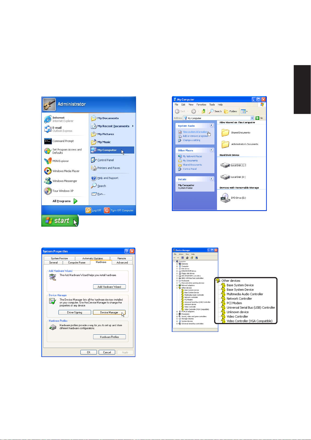
Device Manager
“Device Manager” will be used in many device driver installations, upgrades, and verification processes.
Refer to the following steps on accessing the device manager.
Software Reference
1. Click the “start” button.
2. Click the “My Computer” icon.
4. Click the “Hardware” tab.
5. Click the “Device Manager” button.
3. Click the “View system information” link.
After a new Windows installation, it is normal
to see several question marks under “Other
devices” representing hardware devices that
Windows cannot recognize. After installing
the drivers from the provided support CD,
those question marks will go away.
9
Page 11

Software Reference
10
Page 12

VGA Driver
(Required Driver)
Topics Covered:
VGA Driver Setup
Display Settings for Windows XP
Software Reference
Screens will vary depending on your operating system but the contents should be the same.
11
Page 13
Software Reference
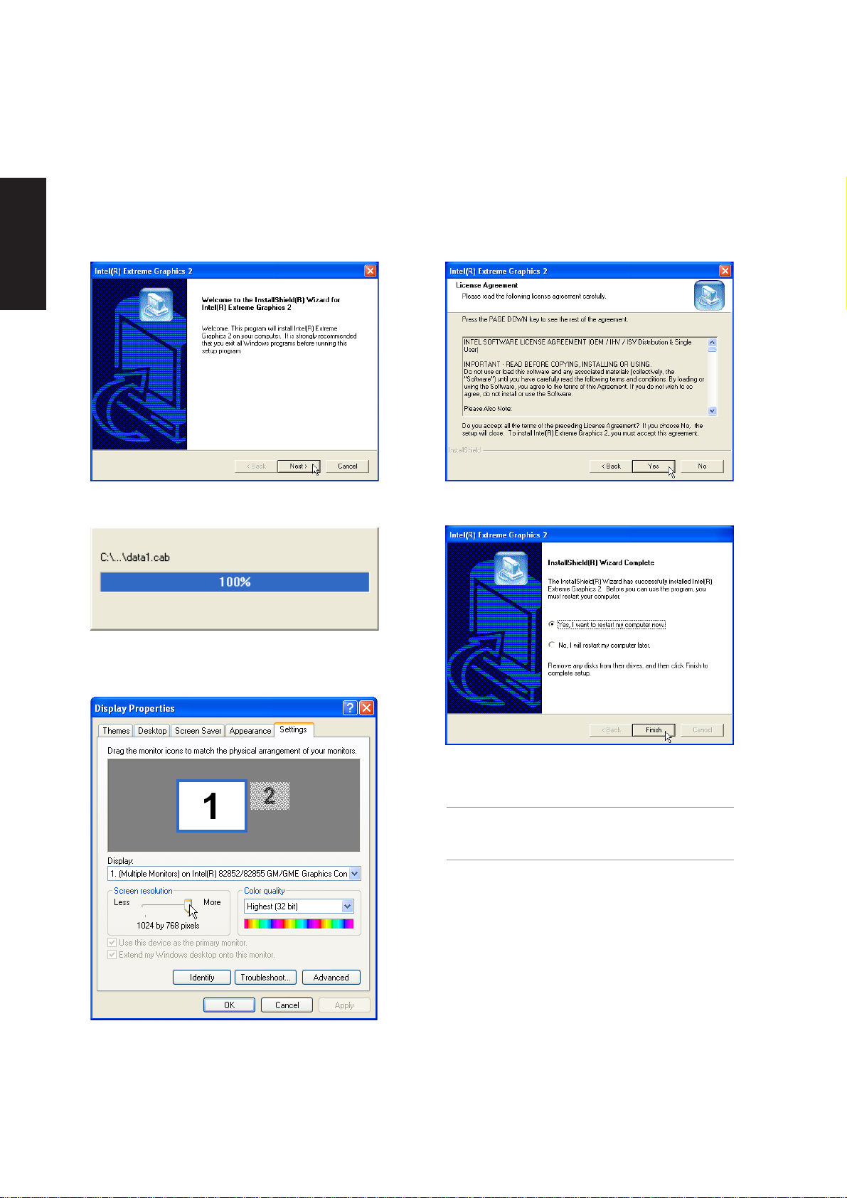
VGA Driver Setup
Running setup will give you the following wizard. See next page for VGA settings.
1. On the “Welcome” screen, click Next after
reading the message.
3. Wait while files are being copied to your
Windows.
2. On the “License Agreement” screen, click Next
after reading the message.
4. Setup is now complete, select “Y es...” and click
Finish in order to restart Windows with a higher
screen resolution*.
*Windows may have already provided the
highest screen resolution support for this
graphics controller.
12
5. Set the screen resolution: Right-click the
desktop and select Properties. Click on the
Settings tab and slide the pointer to the right.
Page 14

ASUS_WLAN
(Required driver for models with ASUS wireless LAN)
Topics Covered:
Wireless LAN Driver Setup
Wireless LAN Utility Setup
Wireless LAN Utility Quick Start
Software Reference
Screens will vary depending on your operating system but the contents should be the same.
13
Page 15
Software Reference
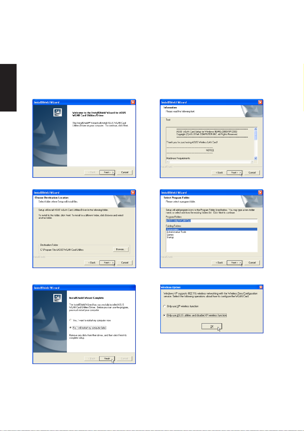
Wireless LAN Driver Setup
This setup will install both drivers and utilities for the wireless LAN device. Running setup will give you the
following wizard:
1. Click Next after reading the “W elcome” screen.
3. On the “Choose Destination Location” screen,
click Next to continue or first change the path.
2. Click Next after reading the “Information” screen.
4. On the “Select Program Folder” screen, click
Next to continue or enter a dif ferent folder name.
5. Click Finish on the “Setup Complete” screen.
14
6. Select to use “...ASUS Utilities...” for added
features while using the wireless LAN device.
Page 16
ASUS WLAN Utility Setup (Cont’)
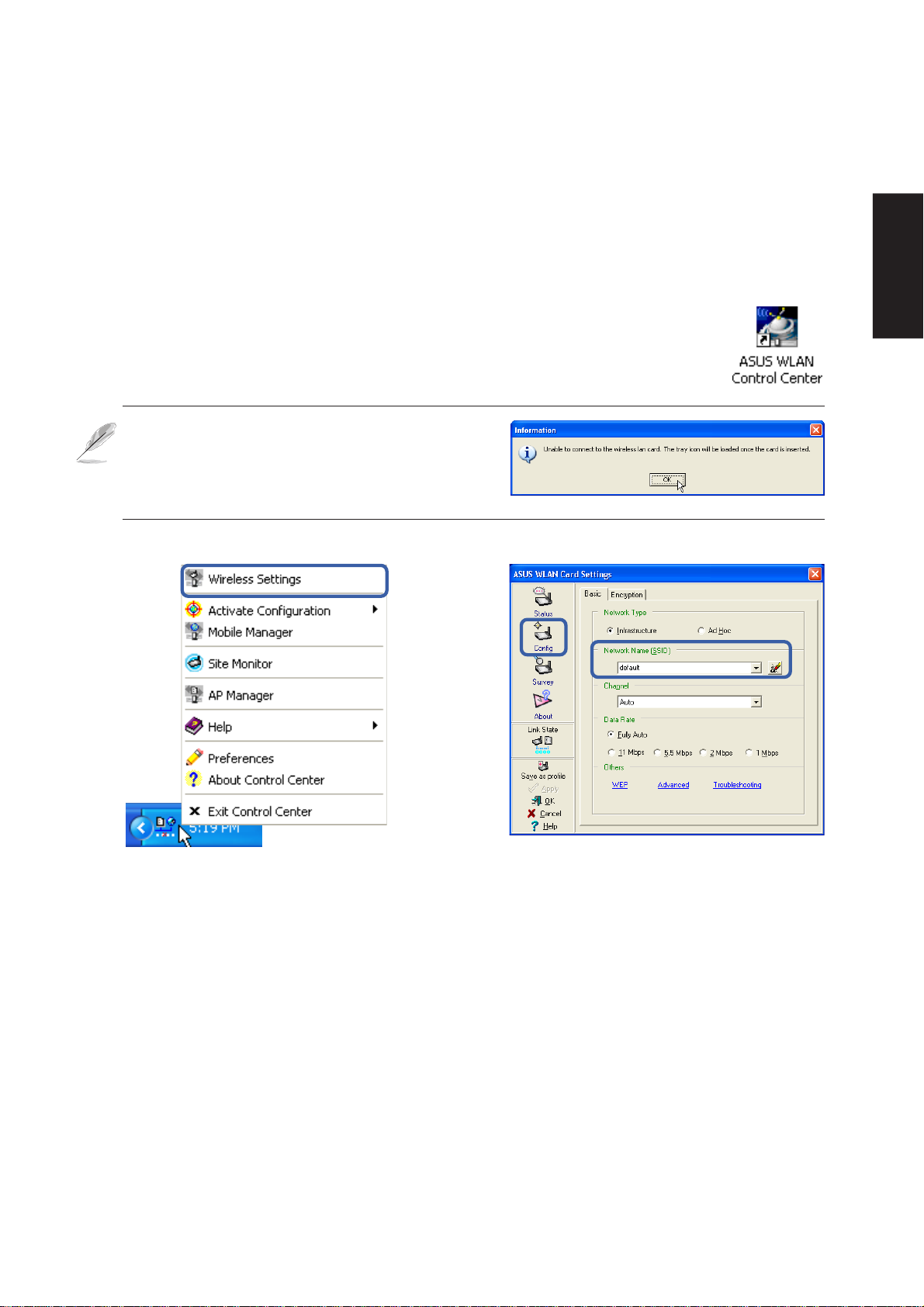
ASUS WLAN Utility Quick Start
After installing the ASUS WLAN driver and utility , the utility will automatically start with
Windows. If you need to start it manually , you can launch the utility using the desktop icon
or through Windows start. You will need to make some wireless LAN settings before
being able to use your wireless connection.
If you receive this message when trying to launch
the ASUS WLAN Control Center . Your Notebook
PC model may use Intel Calexico wireless LAN.
See the next few pages on setting up and using
the Intel Calexico wireless LAN.
Software Reference
(Right-Click Menu)
1. Right-click the ASUS WLAN icon and select
“Wireless Settings”
2. Set the Network Name (SSID) to the same
name as the SSID set in your wireless access
point.
15
Page 17
Software Reference
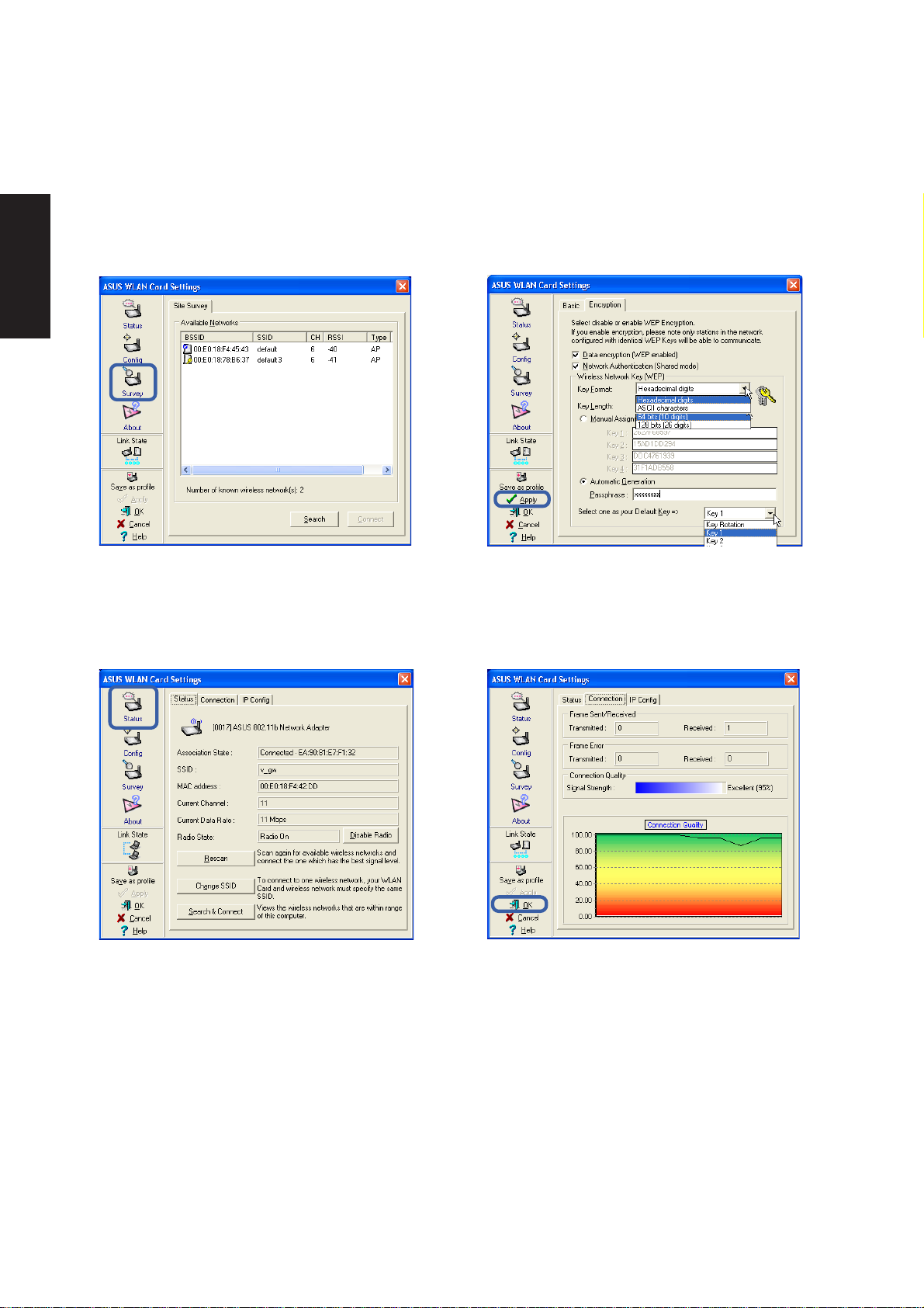
ASUS WLAN Utility Quick Start (Cont.)
3. Use “Site Survey” if you don’t know the name
of your access point(s).
5. Check the “Status” page to see the “Association
State”. It should show “Connected xx:xx:xx:xx:xx:xx”.
4. Encryption settings must also match those set
in the access point. Talk with your network
administrator if necessary. Click Apply to save
your settings
6. You can also see the connection quality on
the “Connection” page. Click OK to exit the utility .
16
Page 18

INTEL_Calexico
(Required driver for models with Intel wireless LAN)
Topics Covered:
Wireless LAN Driver Setup
Wireless LAN Utility Setup
Wireless LAN Utility Quick Start
Software Reference
Screens will vary depending on your operating system but the contents should be the same.
17
Page 19
Software Reference
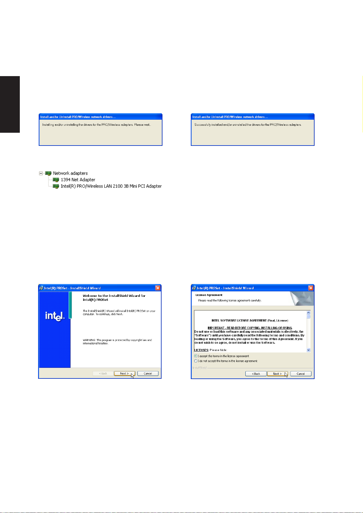
INTEL Calexico Setup
This is the wireless LAN driver . Running setup will automatically install the driver.
When complete, you will see “Intel(R) PRO/
Wireless LAN 2100 3B Mini PCI Adapter” in
device manager.
PROSet Setup
This is the wireless LAN utility . Running setup will give you the following wizard.
1. On the “Welcome” screen, click Next after
reading the message.
2. On the “License Agreement” screen, click Next
after reading the message and selecting “I
accept...”.
18
Page 20
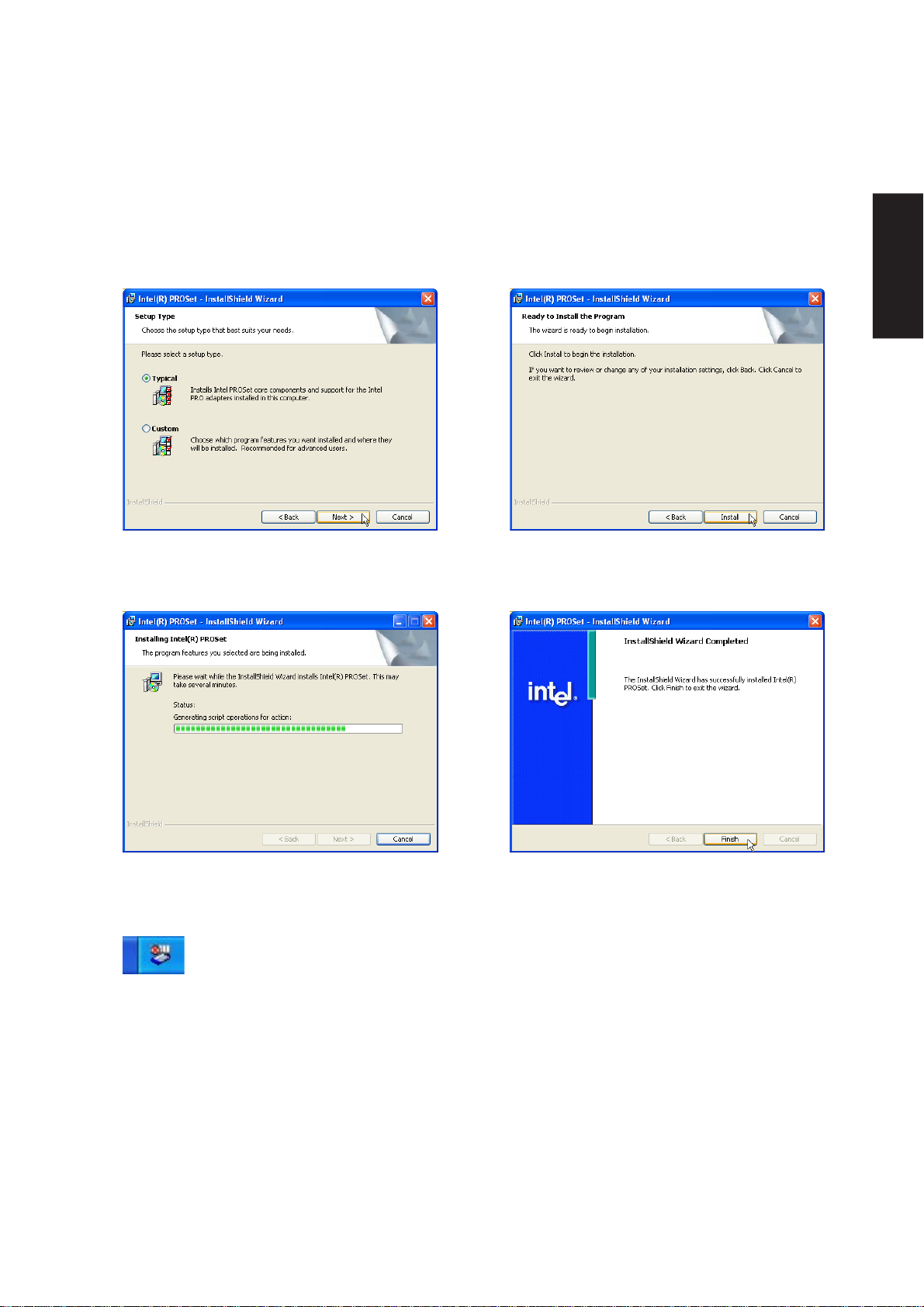
PROSet Setup (Cont.)
Software Reference
3. On “Setup Type” screen, select T ypical and
click Next to continue.
5. Wait while files are installed and configured.
After setup, the PROSet icon will
appear on the Windows taskbar.
4. Click Install to continue.
6. Setup is now complete, click Finish to exit the
wizard.
19
Page 21
Software Reference
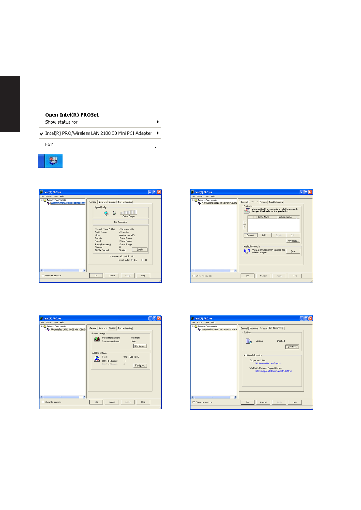
PROSet Utility
This is the wireless LAN utility . You can use the Help button for more information.
Launch Intel PROSet utility by rightclicking the icon on the taskbar and
selecting “Open Intel(R) PROSet”.
This is the main page that gives the wireless LAN
status. Select “Switch radio: On or Off” to enable
or disable the built-in wireless LAN.
If the icon is not available, launch Intel PROSet
utility through Windows start button and find “Intel
Network Adapters”.
The “Networks” page is used to search and add
wireless LAN networks including Ad hoc (peer to
peer) connections.
This is the “Adapter” page that allows you to
configure power and Ad Hoc settings.
20
The “Troubleshooting” page is used to view
wireless LAN statistics and find the
manufacturer’s contact information.
Page 22
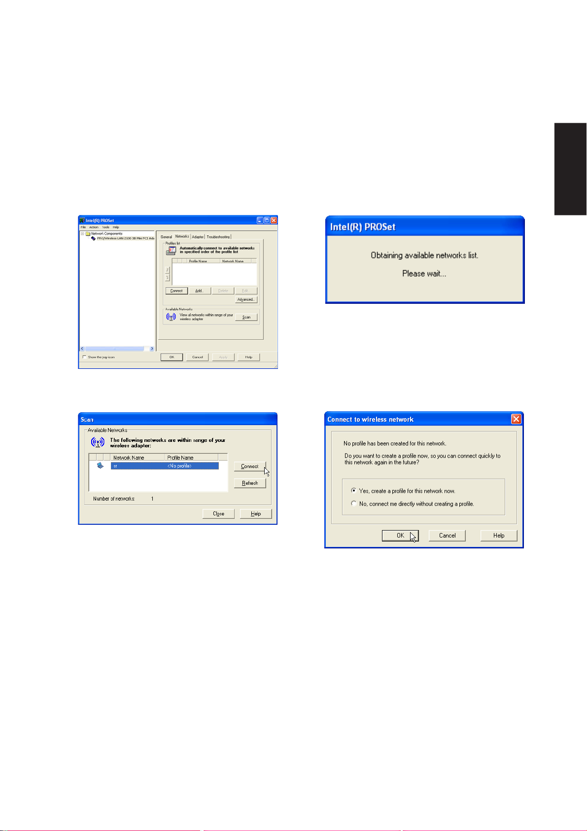
Connecting to a wireless LAN
Follow these steps to connect to a wireless LAN.
Click Scan on the Networks page.
Software Reference
Intel PROSet will scan for Access Points or peers
with broadcasting enabled.
Once a wireless LAN connection is discovered,
you can click the Connect button.
If there is no record of this connection, you will
be allowed to create a profile so that you can
easily roam between different wireless
connections.
21
Page 23
Software Reference
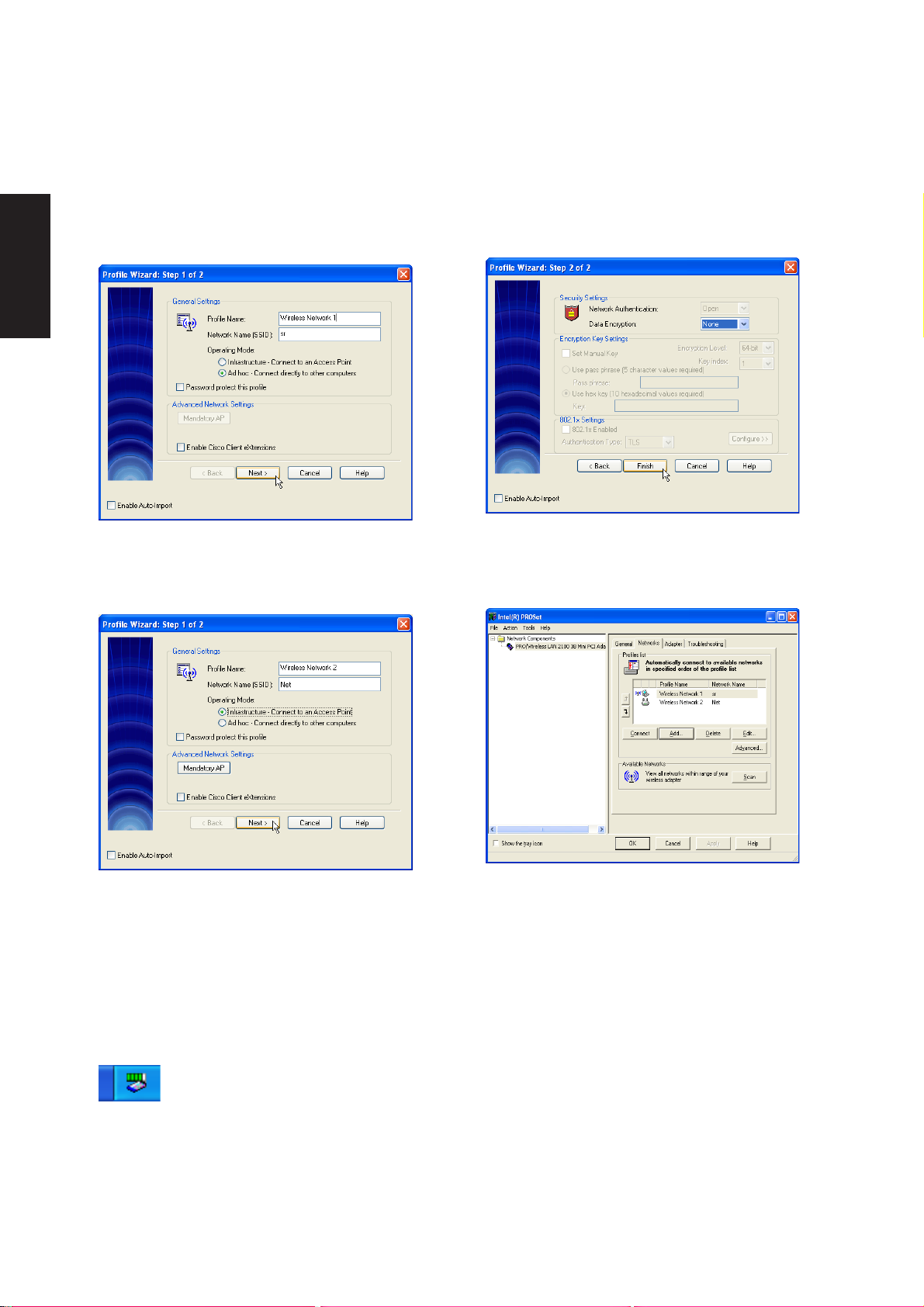
Connecting to a wireless LAN (Cont.)
Type a “Profile Name”. The “SSID” and “Operating
Mode” will be automatically set. Ad hoc
connections are usually to a nearby computer and
probably uses the owner’s name or initials.
Add other wireless connections if necessary.
Acess Points may have their broadcasting service
disabled to prevent unwanted connections. You
need to obtain the SSID and enter it manually.
Security settings may also be required on the next
page.
Make settings on this page if necessary.
Your defined wireless connections will show on
this page.
22
When complete, the taskbar icon will
show green bars indicating a good
connection and the signal strength.
Page 24

Topics Covered:
ATKACPI Setup
ATK0100
(Required Utility)
Software Reference
Screens will vary depending on your operating system but the contents should be the same.
23
Page 25
Software Reference
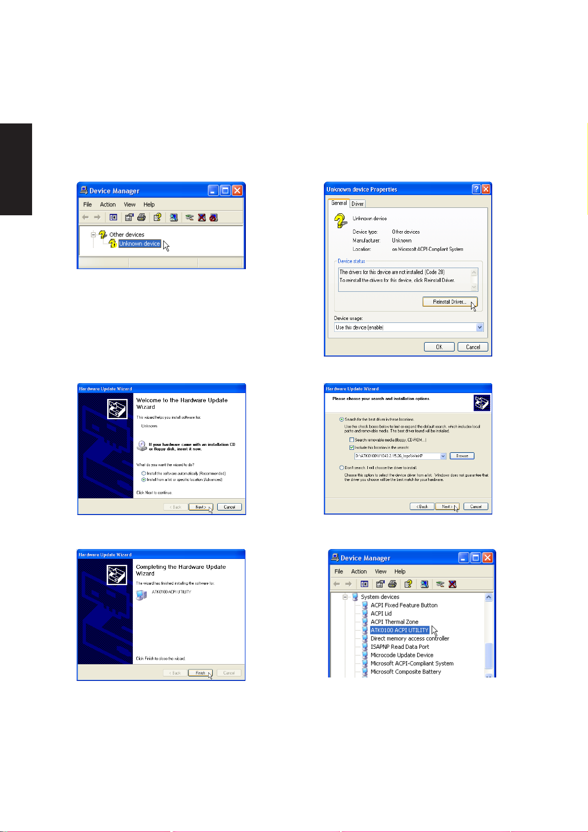
ATK0100 Setup
This utility requires that you manually install it from Device Manager . No software operation is required.
1. Double click Unknown device.
2. Click Reinstall Driver.
24
3. Select “Install from...” and click Next. 4. Browse to your operating system folder
in the “A TK0100” folder and click Next.
5. Click Finish when setup is complete. 6. “ATK0100 ACPI UTILITY” should show
under System devices.
Page 26

Topics Covered:
Audio Setup
Realtek Audio Utility
Audio
(Required Driver)
Software Reference
Screens will vary depending on your operating system but the contents should be the same.
25
Page 27
Software Reference
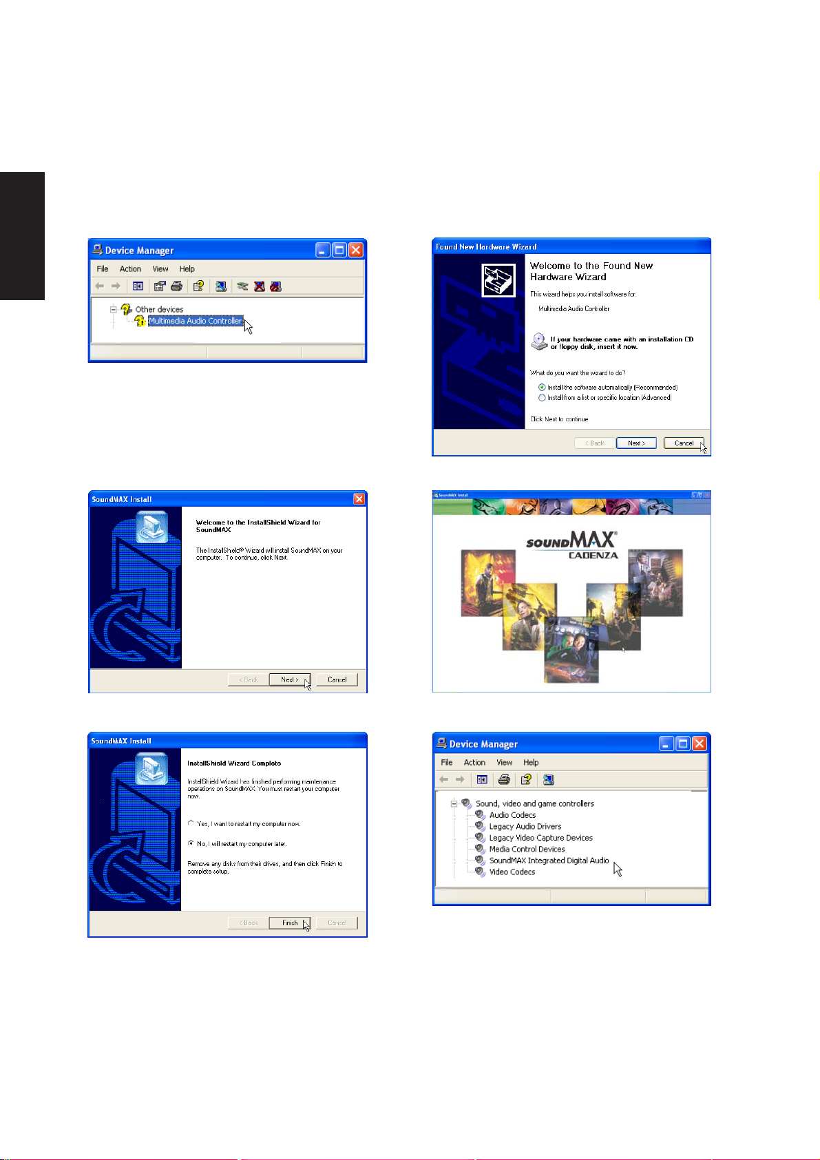
Audio Setup
Running setup will give you the following wizard:
1. Normally , you will get a “Found New Hardware
Wizard” as shown on the next step. If not, double
click the Audio Controller with a question mark in
“Device Manager”.
2. On the “Found New Hardware Wizard” screen,
click Cancel in order to use the audio setup program.
3. On the “Welcome” screen, click Next to begin
the setup wizard.
5. Select No... and click Finish in order to install
other drivers and utilities.
26
4. Wait while files are being copied to your hard
drive.
6. When the device driver is properly setup, it will
appear as the above in “Device Manager”.
Page 28

CPU Hotfix
Topics Covered:
CPU Hotfix Setup 1
CPU Hotfix Setup 2
(Required Driver)
Software Reference
Screens will vary depending on your operating system but the contents should be the same.
27
Page 29
Software Reference
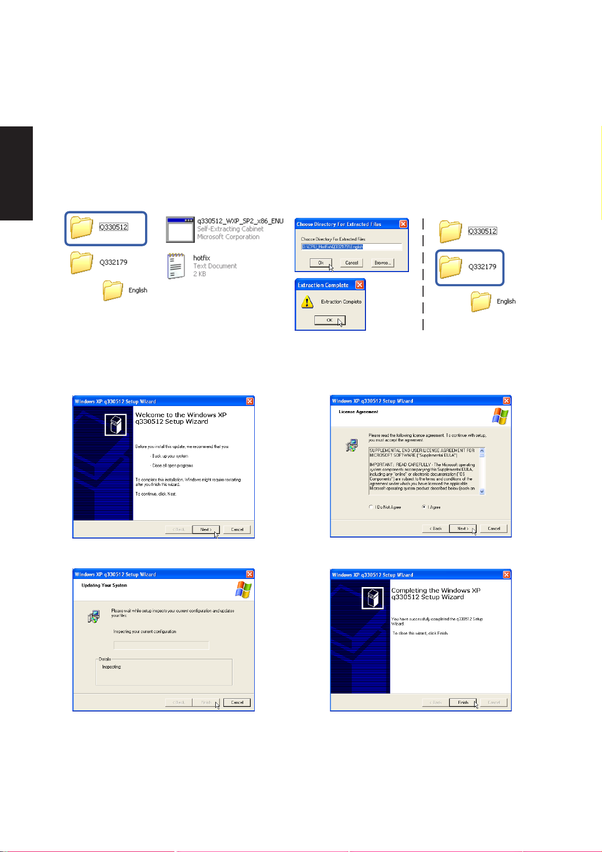
CPU Hotfix Setup 1 of 2
T wo setups are required. There are several languages available in each folder. After setup, restart Windows
and your Windows will be able to utilize advanced features in Intel’s latest mobile processor. The first file
will extract to a separate folder. Read “hotfix” for setup instructions.
CPU Hotfix Setup 2 of 2
The second file has a setup wizard as follows.
28
1. Click Next on the welcome screen.
3. Wait while setup is in progress. 4. Click Finish after setup is complete.
2. Click Next after selecting “I Agree” on the
License Agreement.
Page 30

INFupdate
Topics Covered:
Intel INF Update Setup
(Required Driver)
Software Reference
Screens will vary depending on your operating system but the contents should be the same.
29
Page 31

Software Reference
INFupdate Setup
Running setup will give you the following wizard. No other configurations are necessary .
1. On the “Welcome” screen, click Next after
reading the message.
3. On the “Readme” screen, click Next after
reading the message.
2. On the “License Agreement” screen, click Yes
after reading the message.
4. Setup is now complete, select “No...” and click
Finish in order to install other items.
30
Page 32

Topics Covered:
LAN Driver Setup
Configuring your LAN
LAN
(Required Driver)
Software Reference
Screens will vary depending on your operating system but the contents should be the same.
31
Page 33

Software Reference
LAN Driver Setup
Running setup will give you the following wizard.
1. On the “Welcome” screen, click Next after
reading the message.
2. Setup is now complete, click Finish to exit the
wizard.
32
Page 34

Configuring your LAN
Joining a Domain or Workgroup (Windows XP)
Software Reference
(1) Click Start and My Computer.
(3) Your computer name, workgroup or
domain information is shown here. Click
Change to view options.
(2) Click View system information.
You cannot use spaces or symbols in the
computer name. In the example here, a warning
is given when trying to use “Notebook PC”. Y ou
can use the single word “Notebook” instead.
33
Page 35

Software Reference
Joining a Domain or Workgroup (Windows XP) Cont’
(4a) Domain:
The primary server in the domain will perform
routing functions and security verifications for
your computer. Select Domain and enter an
existing domain you wish to join. NOTE: After
clicking “OK”, you will be asked for the Domain
Controller’s Administrator password to join the
domain in Windows XP.
(4b) Workgroup:
If your network does not have a domain or
you are not authorized to join a domain, select
Workgroup and type in an existing name or
create your own (by typing an unused
workgroup name)
Administrator Name or Password not
accepted: You cannot login with the
Administrator name and use one password,
then use the Administrator name with another
password to add to a domain. You must login
using another name. See Windows
documentation to “Add New User” from User
Accounts in the Control Panel.
34
Page 36

Joining a Domain or Workgroup (Windows XP) Cont’
(5) After you restart your computer, you should
see some contents through Entire
Network.
Viewing Your Network
Software Reference
(6) Clicking on “My Network Places” will display
networks which you have installed protocols
for. Clicking a network protocol such as “MS
Windows Network” will display all the servers
available under that protocol.
35
Page 37

Software Reference
36
Page 38

Topics Covered:
Modem Setup
Modem Configuration
Modem
(Required Driver)
Software Reference
Screens will vary depending on your operating system but the contents should be the same.
37
Page 39

Software Reference
Modem Setup
Running setup will give you the following wizard.
1. On the “Welcome” screen, click Next after
reading the message.
2. Setup is now complete, click OK to exit the
wizard.
Modem Configuration
Use New Connection W izard in “Network Connections” to start the configuration wizard to your modem.
The New Connection W izard also allows configuration for other communication devices (if available) such
as LAN, ISDN, ADSL, or Bluetooth.
1. Double-click New Connection Wizard in
Network Connections
38
2. Select “Connect to the Internet” and click Next.
Page 40

Modem Configuration (Cont’)
Software Reference
3. Select “Set up my connection manually” and
click Next.
5. Select your modem and click Next.
4. Select “Connect using a dial-up modem” and
click Next.
6. Enter any name to represent your ISP.
7. Enter the dial up number for your ISP.
8. Select one of the security preferences and click
Next.
39
Page 41

Software Reference
Modem Configuration (Cont’)
9. Enter your ISP account name and password
and click Next.
MS.SD
MMC
11. Connect a telephone cable from your
Notebook PC to a telephone jack.
10. Select “Add a shortcut...” and click Finish.
40
12. When you click on the link, the connection
window will show. Click Dial to connect to your
ISP.
Page 42

Topics Covered:
2.0
USB Setup
Manual Setup
USB2.0
(Required Driver)
Software Reference
Screens will vary depending on your operating system but the contents should be the same.
41
Page 43

Software Reference
USB2.0 Setup
Running setup (in Windows XP) will give you the following message. USB 2.0 driveres are provided in
Windows XP SP1 and W indows 2000 SP4. Please visit Microsoft’s web site for information on obtaining a
service pack (SP) if you do not have the latest W indows version.
USB Usage
Simply plug in your USB device to use the USB port. For USB 2.0 speeds, the driver must be properly
installed. Without the driver, your USB device can still use the port at USB 1.1 speeds.
42
Page 44

LiveUpdate
Topics Covered:
LiveUpdate Setup
Using LiveUpdate
Resetting Your BIOS
(Recommended Utility)
Software Reference
Screens will vary depending on your operating system but the contents should be the same.
43
Page 45

Software Reference
LiveUpdate Setup
Running setup will give you the following wizard:
On the “Choose Destination Location” screen,
click Next to continue or you may first change
the destination folder.
On the “Setup Complete” screen, click Finish.
On the “Select Program Folder” screen, click Next
to continue or enter a different folder name.
If you don’t have “ATK0100” installed, you will
get this message. You must “ATK0100” before
using this utility .
44
Page 46

Using LiveUpdate
Software Reference
Close other software to ensure no conflicts.
Newer versions will be shown. Check the items
to update or select “Check all”.
Click OK to connect to the “Live Update” server .
Click OK to download and install the update.
When update is complete, click OK to exit.
You may be instructed to “reset your BIOS”. It
entails pressing [F2] on bootup to enter BIOS
setup and selecting Load Setup Defaults, and
then Exit Saving Changes on the “Exit” menu.
45
Page 47

Software Reference
46
Page 48

PC-cillin 2002
(Recommended Utility)
Topics Covered:
PC-cillin 2002 Features
About Viruses
Technical Support
PC-cillin 2002 Feature Screens
Software Reference
Screens will vary depending on your operating system but the contents should be the same.
47
Page 49

Software Reference
Welcome to PC-cillin 2002
Trend Micro PC-cillin 2002 provides next generation secure computing for today’s personal computers.
More than just antivirus software, PC-cillin includes a Personal Firewall, Site filter, Internet mail scanning,
and more for all your secure computing needs.
Designed for the home or small office user , the friendly interface lets you quickly become familiar with all
the powerful features of the software. However, the program behind the interface uses the latest technology
and provides you with protection from the nastiest viruses, sneakiest Trojans, and the meanest hackers. With
firewall technology , the T rojan System Cleaner tool, and more, PC-cillin gives you peace of mind whenever
you connect to the Internet. And now that Trend Micro's award winning ICSA approved scan engine also
includes ScriptTrap technology, personal computing has never been more secure.
Here's what PC-cillin will do "straight out of the box":
• Checks for viruses every time you open, copy, move, or save a file
• Protects against downloading infected files from the Internet or FTP sites
• Guards against malicious Java applets and Microsoft ActiveX controls while surfing the Web
• Detects and cleans live Trojans installed on your system
• Monitors your Microsoft Word and Microsoft Excel sessions for macro viruses, using MacroTrap
• Scans and cleans all files on your hard drive
• Scans all program files for viruses
• Checks all your saved documents for macro viruses
Here's what you can do with just a click of a button:
• Scan every file on your system and clean any infected files
• Scan any file from Windows Explorer or My Computer by right-clicking the file icon
• Scan floppy disks and clean any infected files
• Check all of your Word and Excel document(s) for macro viruses
• Scan your email attachments as they are being downloaded from an Internet (POP3) mail server
• Protect your computer against attacks from the Internet using a combination of cloaking and firewall
functions
• Make whatever Web sites you want "off limits" to other users of the computer
• Protect your handheld devices with updated Personal Digital Assistant (PDA) virus pattern files
48
Page 50

Personal Firewall
PC-cillin 2002 provides secure Internet computing with its new Personal Firewall feature. Easy to operate,
the Personal Firewall protects your computer from unwanted Internet connections. The Personal Firewall is
ideal for computers using always-on broadband (DSL, cable modem) connections, or for those computers
that are often online. Even computers that only connect to the Internet for short periods of time are still
vulnerable to hacker attacks and need protection.
With adjustable security levels, a trusted site list, and a port blocking function, the Personal Firewall gives
you the control to keep your computer safe from malicious code like spyware and Trojan horses. The Personal
Firewall is comprised of the following components:
Cloaking: Prevents your computer from being found. Cloaking hides the entry points (ports) of your computer
making it appear to be disconnected from a network. Hackers using techniques like NetBIOS browsing, port
scanning, or ICMP packet special processing will be unable to locate your computer.
Firewall: Provides a barrier between your computer and the network (LAN, Internet). This barrier examines
and filters network traffic coming into your computer. By filtering network traffic, the firewall prevents
malicious programs or files from entering your computer. The firewall protects against attacks hackers
commonly use including: Ping of Death, IP conflict, SYN flooding, and others.
Trojan Backdoor Blocking: If a hacker has already broken into your system, he or she could have installed a
Trojan (small hidden program) onto your computer (unlike viruses, T rojans do not replicate themselves, but
can still wreak havoc on your system). To avoid being traced, the hacker can then use your computer to
attack other computers. The T rojan Backdoor Blocking function prevents hackers from using your computer
by blocking Back Orifice, Back Orifice 2000, Net Bus, Deep Throat and other known back door programs.
Software Reference
There may be Web sites that you know are safe and will not attack your computer. Using the Trusted Sites
function, the Personal Firewall lets you add these safe sites to a list. Your computer can connect to any W eb
site on this list because they will not be filtered.
PC-cillin for Wireless
Malicious code and other threats hidden inside files, email, or on the W eb can enter your Palm, Pocket PC, or
EPOC device during beaming, synchronization, or Internet access. Trend Micro PC-cillin for Wireless provides
portable, easy-to-use antivirus security for wireless devices; to defend against potential threats. Best of all,
PC-cillin for Wireless is bundled with PC-cillin 2002 providing you with secure computing on both your
desktop and handheld.
Trojan System Cleaner
PC-cillin automatically runs the Trojan System Cleaner (TSC) during initial installation, and every time
Real-time Scan runs. The TSC detects the activity of T rojan horse programs, recovers system files which are
modified by Trojans, stop their processes, and deletes files dropped from Trojans.
49
Page 51

Software Reference
Traditional antivirus products only scan "files", they open files and check for virus code. But they don't
check and clean system files and can't clean or delete Trojan horse programs (also known as T rojans) if it is
already run in the system.
The TSC uses patterns to define how to clean a T rojan. These patterns are built into T rend Micro virus pattern
files and are kept up-to-date. Whenever TSC is executed, it finds the newest pattern file and tries to read
Trojan clean section from the pattern file.
ScriptTrap Technology
With the addition of ScriptT rap technology , PC-cillin now more than ever provides rock-solid protection for
your computer. PC-cillin not only guards against harmful known script-based viruses ("I Love You" and
"Anna Kournikova"), but can also protect your PC from new , unknown script-based threats.
Using the following processes, ScriptTrap automatically scans for scripting viruses based on "what they do"
rather than how they are written:
lexical analysis- divides the script's source code into components, called tokens, based on punctuation and
other keys.
semantic parsing- attempts to determine the meaning of each component.
Emergency Lock
PC-cillin also includes an Internet Emergency Lock function that lets you immediately disable all Internet
activity if you suspect an attack. Enabling the Emergency Lock function immediately stops all traffic to and
from the Internet.
User Interface
Designed for the home or small office user , the program's friendly interface quickly familiarizes you with the
powerful features of PC-cillin 2002. The interface now includes a Simple and Standard mode. Using a tab
interface, you can easily switch between the two modes.
Simple mode: Perform common PC-cillin tasks such as: view a simplified version of your system status, and
scan all drives. In addition, you can update and register your software.
Standard mode: Access more advanced PC-cillin 2002 functions including: viewing your system status in
more detail, selectively scanning folders, synchronizing your PDA, quarantining files, and viewing logs. In
the Standard mode, as in the Simple mode, you can also update and register your software.
50
Page 52

About Intelligent Update
Intelligent Update automatically searches for and downloads the latest files for PC-cillin 2002. This includes
pattern and program files for both the main program and PC-cillin for Wireless. In addition, Intelligent
Update ensures you have the latest Personal Firewall rules. This powerful function keeps PC-cillin and all its
components updated; offering you maximum protection with minimal user intervention.
Once your computer is running, PC-cillin checks for an Internet connection. When this feature is enabled
and your computer is online, PC-cillin automatically connects to the Trend Micro server to check if the latest
update is available. If newer components are on the server, a pop-up window appears asking if you want to
start downloading. If you choose not to download immediately , the pop-up window reappears in 10 minutes.
New product registration method
PC-cillin 2002 offers a new way to register your software online. On our Registration W eb page, simply type
your name and email address in the appropriate fields, receive your License Key via email, and insert it into
the correct field on the Register Now screen of the PC-cillin window .
Registration only takes a few minutes and Trend Micro provides technical support, virus pattern downloads,
and program updates for one year to all registered users, after which you must purchase renewal maintenance.
About viruses
Software Reference
A computer virus is a program that replicates. To do so, it needs to attach itself to other program files (for
example, .exe, .com, .dll) and execute whenever the host program executes. Beyond simple replication, a
virus almost always seeks to fulfill another purpose: to cause damage.
Called the damage routine, or payload, the destructive portion of a virus can range from overwriting critical
information kept on your hard disk's partition table to scrambling the numbers in your spreadsheets to just
taunting you with sounds, pictures, or obnoxious effects.
It is worth bearing in mind, however, that even without a "damage routine," viruses allowed to run unabated
will continue to propagate--consuming system memory, disk space, slowing network traffic and generally
degrading performance. Besides, virus code is often buggy and can also be the source of mysterious system
problems that take weeks to understand. So, whether a virus is harmful or not, its presence on your system
can lead to instability and should not be tolerated.
Some viruses, in conjunction with "logic bombs," do not make their presence known for months. Instead of
causing damage right away , these viruses do nothing but replicate--until the preordained trigger day or event
when they unleash their damage routines on the host system or across a network.
To learn more about any particular virus, or about viruses in general, you can access Trend Micro's online
V irus Encyclopedia at: www.antivirus.com/.
51
Page 53

Software Reference
How viruses are created
Until a few years ago, creating a virus required knowledge of a computer programming language. Today
anyone with even a little programming knowledge can create a virus. Usually , though, misguided individuals
who want to cause widespread, random damage to computers create viruses.
In the typical scenario, it is an individual, working alone, who writes a virus program and then introduces it
onto a single computer, network server , or the Internet. Why? Ego, revenge, sabotage, and basic disgruntlement
have all been cited as motivations. Recently , do-it-yourself "virus kits" have been popping up on the Internet,
and macro scripts are becoming both easier to learn and more powerful, putting the capacity to engineer
viruses in the hands of nearly everyone. In other words, no single, likely profile exists by which virus writers
can be described or understood.
So whatever the reason one may have for writing a virus, the important thing is to make certain your company
is not victimized, that data you are responsible for is safe, and that precious time is not wasted hunting down
(and cleaning up after) viruses.
Accessing the Trend Micro V irus Encyclopedia
PC-cillin includes access to the online Trend Micro virus encyclopedia, organized by name and virus type.
Use it to find out about tens of thousands of individual viruses, including the typical symptoms of a given
virus, its infection procedure, and the damage routine.
With the growing prevalence of Macro viruses, we have bolstered the number of Macro virus descriptions
included in the encyclopedia to well over 2000.
Of course, PC-cillin, which uses Trend’s award-winning, 32-bit, multi-threading scan engine, is capable of
detecting all viruses that are known to be in circulation, plus the many thousands more that exist as "proof of
concept" only in researcher's virus labs and on hacker's computers.
T o access the Trend Micro V irus Encyclopedia, on the PC-cillin menu bar , click Security Info > Encyclopedia..
Viewing the Trend Micro Virus list
The Virus Information Center contains a list of the Real-time top ten viruses. In addition, you can view
updated Security Alerts and Virus Advisories.
T o access the Trend Micro Virus list, on the PC-cillin menu bar click, Security Info > Virus List.
Contacting Technical Support
Trend Micro provides technical support, virus pattern downloads, and program updates for one year to all
registered users, after which you must purchase renewal maintenance.
Send an email to our highly trained technical support staff or visit our Web site to receive technical support.
52
Page 54

Trend Micro Technical Support
Email: support@trendmicro.com
URL: www.antivirus.com
To speed up your problem resolution, when you contact our staff please provide as much of the following
information as you can:
• Product serial number
• PC-cillin program, scan engine, pattern file, version number
• OS name and version
• Internet connection type
• Exact text of any error message given
• Steps to reproduce the problem
Before Contacting Technical Support
While our technical support staff is always pleased to handle your inquiries, there are a couple things you can
do to quickly find the answer you are seeking.
• Check the documentation: the manual and online help provide comprehensive information about PC-
cillin. Search both documents to see if they contain your solution.
Software Reference
• Visit our technical support Web site: our technical support Web site contains the most up-to-date
information about all Trend Micro products. Other inquiries that were already answered are also
posted on the support Web site.
53
Page 55

Software Reference
PC-cillin 2002 Feature Screens
PC-cillin 2002 Real-time Monitor
The Real-time Monitor is the quickest way to
access certain functions, for example to display
the PC-cillin or Settings windows. With the Realtime Monitor, you know at a glance if real-time
scanning is enabled (the lightning streak icon is
red) or disabled (the lightning streak icon is grey).
Configuration Screen
Double click the PC-cillin icon on the taskbar to
bring up the real-time scan information page. Or
right click and select “Configuration”.
The PC-cillin software has many features to
protect you from V irus threats. Use the Help for
more information.
The Emergency Lock is activated. All incoming
and outgoing Internet traffic is halted.
PC-cillin is connecting to the Trend Micro server
to download the latest updates.
Y our computer is currently under attack.
The real-time scanning function is enabled.
The real-time scanning function is disabled.
Real-time Status
Select “Real-time Status” by right clicking on the
PC-cillin icon and you will bring up information
on your virus pattern version, last scanned file,
and network activity .
Stop Network Activity
Click the large button with a computer and broken
network cable to stop all network activity if you
suspect harmful activities are being made to your
computer from the network.
54
Page 56

Power4 Gear
Topics Covered:
Power4 Gear Setup
Benefits of Power4 Gear
Power4 Gear Interface
Power4 Gear Configuration
Software Reference
Screens will vary depending on your operating system but the contents should be the same.
55
Page 57

Software Reference
Power4 Gear Setup
Running setup will give you the following wizard:
On the “Welcome” screen, click Next after reading
the message.
On the “Select Program Folder” screen, click Next
to continue or enter a different folder name.
On the “Select Program Folder” screen, click Next
to continue or enter a different folder name.
On the “Setup Complete” screen, click Finish.
If you don’t have “ATK0100” installed, you will
get this message. You must “ATK0100” before
using this utility .
56
Page 58

Benefits of Power4 Gear
Power4 Gear gives you control over power consumption items by allowing you to instantly “shift” from one
power consumption scheme to another. The four preferences or “gears” are shown below . You can change or
“shift” gears by using the Power4 Gear button above the keyboard or by using the task bar icon. Power4 Gear
can also be automatically activated when AC power is removed.
Power4 Gear Interface
Understanding the Power4 Gear buttons
Press the Power4 Gear button above the taskbar to shift between the four gears as labeled below.
The icon may vary depending on your Notebook PC model.
Software Reference
Maximum Performance
High Performance
Medium Performance
Maximum Power Savings
If your Notebook PC has overclocking
options and is enabled, the airplane
will be replaced with a rocket.
57
Page 59

Software Reference
Using the task bar icon
Right-click the icon on the taskbar for quick access to Power4 Gear settings.
If your Notebook PC
has overclocking
options and is enabled,
the airplane will be
replaced with a rocket.
Power4 Gear Modes
When you are using an AC adapter , the Power4 Gear button will switch between two modes as shown below .
When you remove the AC adapter, the Power4 Gear button will switch between three modes as shown
below. When you remove or apply the AC adapter, Power4 Gear will automatically shift you up or down into
the proper mode segment.
If your Notebook PC has
overclocking options and is
AC Mode
Segment
Battery Mode
Segment
58
enabled, the airplane will be
replaced with a rocket.
Page 60

Power4 Gear Configuration
Double click an item to bring up a menu of selections and
click on a value to change. To save, select “Save
Configuration” form the “File” pull-down menu. If you did
not save, you will be prompted to when you exit.
Maximum Performance High Performance
Medium Performance Maximum Power Savings
Software Reference
Renaming Settings
You can rename the four power saving levels as
you like using the same method to rename files
or folders in Windows.
See next page for available selections for each “gear”.
59
Page 61

Software Reference
Power Saving Details
System Standby Timer CPU Performance
Hard Drive Off Timer
Display Panel Off Timer
60
Display Panel Brightness
(in Medium Performance or Maximum Savings)
Page 62

ASUS Probe
Topics Covered:
ASUS Probe Setup
ASUS Probe Reference
Starting ASUS Probe
Using ASUS Probe Monitoring
ASUS Probe Task Bar Icon
Software Reference
Screens will vary depending on your operating system but the contents should be the same.
61
Page 63

Software Reference
Probe2 Setup
Running setup will give you the following wizard:
On the “Welcome” screen, click Next after reading
the message.
On the “Select Program Folder” screen, click Next
to continue or enter a different folder name.
On “Choose Destination Location” , click Next to
continue or enter another destination folder.
On the “Setup Complete” screen, deselect
“...restart my computer now” so you can install
other items and restart later. Click Finish.
62
Page 64

ASUS Probe Reference
ASUS Probe is a convenient utility to continuously monitor your computer system’s vital components,
such as fan rotations, voltages, and temperatures. It also has a utility that lets you review useful information about your computer, such as hard disk space, memory usage, and CPU type, CPU speed, and
internal/external frequencies through the DMI Explorer.
Starting ASUS Probe
If the ASUS Probe icon (magnifying glass) is not shown on the taskbar (see below), click the Windows
Start button, point to Programs, and then ASUS Utility, and then click Probe VX.XX.
When ASUS Probe starts, a splash screen appears allowing you to select whether to show the screen
again when you open ASUS Probe or not. To bypass this startup screen, clear the Show up in next
execution check box.
Software Reference
The ASUS Probe icon will appear on the taskbar’s system tray indicating that ASUS Probe is running. Clicking the icon once will allow open the ASUS Probe interface.
Windows XP Taskbar
Windows XP will hide taskbar items. Click the arrow to show running services.
63
Page 65

Software Reference
Using ASUS Probe Monitoring
Monitor Summary
Shows a summary of the items being monitored.
Settings
Lets you set threshold levels and polling intervals
or refresh times of the PC’s temperature, fan
rotation, and voltages.
Temperature Monitor
Shows the PC’s temperature.
History
Lets you record the temperature monitoring
activity by date, time, and target history. Click
the record button and select a date. To view a
previous recording, simply choose that date.
64
Page 66

Using ASUS Probe Monitoring (Cont’)
Information
Software Reference
Hard Drives
Shows the used and free space of the PC’s hard
disk drives and the file allocation table or file
system used. Information on other hard drives can
be accessed by clicking on the relevant drive letter.
DMI Explorer
Shows information pertinent to the PC, such as
CPU type, CPU speed, and internal/external frequencies, and memory size.
Memory
Shows the PC’s memory load, memory usage,
and paging file usage.
ASUS Probe Taskbar Icon
Right clicking the ASUS Probe icon will bring
up a menu to open or exit ASUS Probe and pause
or resume all system monitoring.
When the ASUS Probe
senses a problem with
your PC, portions of
the ASUS Probe icon changes to red and audio
alerts will be heard from the speaker.
65
Page 67

Software Reference
66
Page 68

TouchPad
(Recommended Utility)
Topics Covered:
TouchPad Setup
Overview of the TouchPad
Scrolling Properties Page
Tap Zones Properties Page
More Features Properties Page
Button Actions Properties Page
Touch Properties Page
Edge Motion Properties Page
Frequently Asked Questions
Software Reference
Screens will vary depending on your operating system but the contents should be the same.
67
Page 69

Software Reference
Touchpad Setup
Running setup will give you the following wizard:
On the “Choose Setup Language” screen, select
a language and click OK to continue.
On the “Information” screen, click Next after
reading the message.
On the “Welcome” screen, click Next after reading
the message.
On the “Start Copying Files” screen, click Next
after checking the current settings.
On the “Setup Complete” screen, select
“No,...”and click Finish.
68
Page 70

Synaptics® TouchPad Features
Your Synaptics TouchPad is much more powerful than an old-fashioned mouse. In addition to providing all
the features of an ordinary mouse, your TouchPad allows you to:
• Tap on the Pad Instead of Pressing the Buttons
• Drag Icons, Windows and Other Objects without Using Buttons
• Adjust the Overall Touch Sensitivity
• Customize Buttons and Taps
• Prevent Accidental Pointing While Typing (also known as Palm Check)
• Scroll Through a Document Without Using Scroll Bars
• Zoom In/Out and Pan on Documents
• Move the Pointer Long Distances
• Fine Tune the Pointer Movement
Tap on the Pad Instead of Pressing the Buttons
T apping on the surface of the pad is the same as clicking the left mouse or TouchPad button (i.e. the primary
T ouchPad button). Tapping is usually quicker and more convenient than using the button. T o double-click,
just tap twice. A light, quick tap works best; very hard or very slow taps are less likely to work.
Drag Icons, Windows and Other Objects without Using Buttons
Software Reference
Often, you need to hold the mouse or T ouchPad button down while moving the pointer (to move an icon or
window around the screen, for example). This action is called dragging. Just like clicking and double
clicking, you can also drag without using the button.
To move or drag an object (equivalent to pressing and holding the left TouchPad button):
1) Position the pointer over the object and tap twice, down-up-down, leaving your finger on the T ouch-
Pad on the second tap. This action is sometimes called tap-and-a-half.
2) Now move the selected object by sliding your finger across the TouchPad surface.
3) Lift your finger to drop the object.
Tap-and-a-Half
You might wonder what happens when you reach the edge of the pad and you are dragging an object. The
Synaptics T ouchPad has a feature called Locking Drags. This feature allows you to lift your finger from the
pad without ending the drag. You can drag an object across the screen using several finger strokes. T o end
a Locking Drag action, tap again. The Synaptics TouchPad also has a feature called Edge Motion to help
with long distance dragging. See Move the Pointer Long Distances for details.
The Tap and Drag and Locking Drags features are located on the Touch Properties Page in the Mouse
Properties dialog.
69
Page 71

Software Reference
Adjust the Overall Touch Sensitivity
You can control how much finger pressure you must apply before the TouchPad responds by adjusting the
T ouch Sensitivity slider . This slider is located on the Touch Properties Page in the Mouse Properties dialog.
At higher (more sensitive) T ouch Sensitivity settings, the TouchPad recognizes even a very slight touch. If
you see undesired or erratic pointer motion, try a lower setting. Lower (less sensitive) settings require a
firmer touch to move the pointer. In general, a lighter touch works best.
Customize Buttons and Taps
Most T ouchPads come with two buttons that work just like traditional mouse buttons. You can customize the
behavior of these buttons.
T apping on the TouchPad surface also performs the same action as pressing a button. T apping in the center
of the pad will always produce a left-click (the action of the primary button), but you can configure each of
the four corners of the T ouchPad surface to act as different buttons. These special corner regions are called
tap zones . With four corner tap zones, the center of the T ouchPad, and the two physical buttons you can turn
your TouchPad into a seven-button mouse!
A customization example:
Suppose you want to use your TouchPad like a three-button mouse. You can configure the left TouchPad
button to produce middle clicks when pressed. Remember that tapping on the TouchPad will produce left
clicks, and pressing the right TouchPad button will produce right clicks. For additional convenience, you
can configure the top right corner tap zone of the T ouchPad to produce right clicks. Looking at the T ouchPad
surface in the picture below , taps in the top right corner (the red shaded area) will produce right clicks, but
tapping anywhere else on the TouchPad (the solid gray area) produces left clicks.
An Example TouchPad
There are many different actions that you can assign to the buttons and tap zones. The following actions are
provided as built-in features with the Synaptics T ouchPad device driver . Additional actions might be available
if you have installed any third-party TouchPad Plug-In software.
• Jump to the Start Button. This action causes the pointer to jump to the Start button in the Windows
task bar and automatically opens the Start Menu.
• Jump to the current application’s menu. This action causes the pointer to jump to the leftmost entry in
the application’s window menu (usually the File menu) and automatically pops up the submenu.
• Minimize the current application. This action minimizes the current application’s window. If the current
application’s window is already minimized, this action will restore it to its normal size and location.
• Maximize the current application. This action maximizes the current application’ s window (expands
it to cover the full screen). If the current application’s window is already maximized, this action will
restore it to its normal size and location.
• Run a program of your choosing. This action allows you to specify the name of any program you
want to run automatically when you click the button or tap in the tap zone.
T o customize taps and buttons, go to the Button Actions Properties Page in the Mouse Properties dialog.
70
Page 72

Prevent Accidental Pointing While Typing
Unintentional pointer movement and accidental taps can be caused by accidentally brushing the surface of
the TouchPad with your palm or another part of your hand. The results of this contact can be observed as a
changing cursor location when typing, causing subsequent text to appear in the wrong place. Or text may
“spontaneously” be highlighted and replaced. Most often, this unwanted pointing activity occurs when typing
on the keyboard. The TouchPad can detect and prevent accidental and unwanted pointer movement while
you are typing.
If you see unwanted pointer movement occurring while you are typing, you can adjust the Palm Check slider
located on the Touch Properties Page in the Mouse Properties dialog. Move the slider thumb to the right
towards Maximum. Now accidental brushes of your hand on the TouchPad while you are typing are more
likely to be ignored.
On the other hand, in the midst of typing, you might purposefully use the TouchPad to point and click, and
sometimes the TouchPad may not seem to respond. In this case, move the slider thumb to the left towards
Minimum. Now pointing during typing is less likely to be interpreted as an accidental brush with the pad
surface, and will not be ignored.
Scroll Through A Document without Using Scroll Bars
Virtual Scrolling allows you to perform a very common task – scrolling documents – without having to
move the pointer away from your work. By simply sliding your finger up and down the right edge of the
T ouchPad, the contents of the current window will scroll vertically . Similarly , by sliding your finger left and
right along the bottom edge of the TouchPad, the contents will scroll horizontally. You no longer need to
laboriously maneuver the pointer to the small scroll bar elements; you can scroll no matter where the pointer
happens to be.
Software Reference
Virtual Scrolling works with document windows (like word processors and spreadsheets), and it also works
with file lists, font lists, and other scrollable items. As a rule, you can use Virtual Scrolling when you are
working in any window that has a scroll bar.
And V irtual Scrolling does more than just make scrolling more convenient. It also can make scrolling smoother.
When you scroll by dragging the scroll thumb with the mouse, many applications do not re-display the
document window until you release the mouse button. V irtual Scrolling makes navigation through documents
easier, because it forces the application to re-display the window contents as you scroll.
How do I use Virtual Scrolling?
To customize the V irtual Scrolling feature, go to the Scrolling Properties Page located in the Mouse Properties
dialog.
Zoom In/Out and Pan on Documents
Note that zooming and panning only work in applications that support the Microsoft Intellimouse. With
Intellimouse aware applications, you can zoom and/or pan to quickly maneuver your way through lengthy
documents. T o jump to a distant location within your document, zoom out, click on the desired location, then
zoom in. To scroll horizontally and vertically at the same time, simply pan in a diagonal direction!
71
Page 73

Software Reference
Move the Pointer Long Distances
Suppose you are dragging an object, scrolling at high speed (via Virtual Scrolling! ), or merrily moving the
pointer when you suddenly reach the edge of your TouchPad. Don’t despair , the Synaptics TouchPad Edge
Motion feature comes to the rescue! Edge Motion helps with long distance pointer motion. When you reach
an edge of the T ouchPad, the pointer (or scroll thumb when Virtual Scrolling) continues to move in the same
direction until you lift your finger from the TouchPad or move your finger away from the edge.
Edge Motion speed can be pressure-sensitive or constant. Pressure-sensitive speed means that the harder
you press, the faster the object or pointer moves.
You can configure the Edge Motion feature on the Edge Motion Properties Page in the Mouse Properties
dialog.
Fine Tune the Pointer Movement
The Synaptics TouchPad has many additional features to help you control the way your pointer moves.
Please take a look at the list of additional features.
Accessories
Your TouchPad is a productivity enhancing tool, designed for serious work. But we think it should also be
fun. W e have included two fun application programs that demonstrate some of the capabilities of the T ouchPad:
Pressure Graph and The Incomparable, Mysterious Synaptics MoodPad.
To run these applications, click once on the Synaptics TouchPad Icon in the Taskbar, go to the Accessories
menu and select the desired application.
More About the TouchPad
The T ouchPad detects your finger by capacitive sensing (it is not sensitive to heat or applied force). As your
finger approaches the pad, it alters the electric field in the vicinity of the pad surface. The TouchPad sensor
is just a circuit board with a matrix of conductive traces printed on the top surface. A special chip on the back
side of the TouchPad continuously measures the capacitance of these traces, and thus can determine the
presence and location of your finger.
T o get the most out of your T ouchPad, be sure that the T ouchPad driver software is installed. If the Synaptics
T ouchPad driver is properly installed, the Mouse Properties dialog will include several TouchPad tabs along
the top in addition to the standard mouse tabs.
Property Pages
The property pages allow you to customize TouchPad settings for your Notebook PC. The following pages
will describe each property page with the Synaptics logo. The “Buttons”, “Pointers”, and “Pointer Options”
pages come with Windows and should be described in Windows documentation.
72
Page 74

Scrolling Properties Page
The Scrolling properties page allows you to customize the
Virtual Scrolling capabilities of your TouchPad.
In some applications, the scroll zones which activate V irtual
Scrolling can be used for zooming too.
Enabling Virtual Scrolling of the
Active Window
Check the appropriate boxes on this page for the type of V irtual
Scrolling that you prefer:
• Horizontal Scrolling
• Vertical Scrolling
• Coasting
Choose where you want Virtual Scrolling to occur:
• Scroll Selected Item
- OR -
• Scroll Item Under Pointer
Software Reference
Customizing Scroll Zone Sizes
This page includes a small map of the TouchPad with the scroll zones shaded in red. See the Scroll Zone
T ouchPad Map for a more detailed description.
You can adjust the size of each zone by dragging one of the black resize handles on the TouchPad map. If
you are having trouble activating the V irtual Scrolling feature, you might want to try making the scroll zones
wider. If you find that scrolling sometimes gets activated when you didn’ t mean to scroll, try narrowing the
scroll zones.
Customizing Virtual Scrolling Speed
Y ou can control the speed of V irtual Scrolling by adjusting the Scrolling Speed slider on this page. Drag the
slider thumb to the right for faster scrolling.
73
Page 75

Software Reference
Tap Zones Properties Pages
The Tap Zones properties pages allow you to assign custom
actions to taps in the Touchpad’s corner zone regions (or tap
zone regions).
The Synaptics TouchPad driver may also control other
pointing devices attached to your system. If the Synaptics
T ouchPad driver is controlling more than one pointing device
on your system, the Synaptics pages on the Mouse control
panel will have a drop-down box listing all of the pointing
devices that are controlled. You may set separate settings for
each by selecting the appropriate device (settings which don’t
apply to a particular pointing device will be grayed out).
Customizing the Tap Zones
When the tap zones are enabled, each tap inside a corresponding tap zone region on your T ouchPad can have
a different meaning or action. For example, you can define the upper right corner tap zone to mean right
clicks. Then when you tap your finger on the upper right corner of your T ouchPad, it is as if you are clicking
the right mouse or TouchPad button.
This page includes a small map of the TouchPad with the active tap zones shaded in red. Next to each zone
is a text box specifying the action for that zone.
To Customize:
1. T o activate the corner tap zones, check the box next to the text Enable Tap Zones. An unchecked box
means that all taps on every part of the TouchPad surface will have left-click behavior.
2. T o change an action for a particular zone, locate the text box nearest the zone. The text box displays
the current action for this zone (for example, it might say No Zone which means that this particular
zone is disabled and any taps here will produce the default left-click action). Click on the down
arrow button located to the right of the text to display a list of actions. Select the desired action.
3. Each tap zone can be resized to be as large or as small as you desire by dragging one of the black
resize handles located on the TouchPad map.
74
Page 76

More Features Properties Page
The More Features properties page allows you to control the
following features of you Synaptics TouchPad:
Stop Pointer at Window Borders
This feature constrains the pointer to stay inside the active
window. When you try to move the pointer outside the
window, it stops at the edge. If you try a second time, the
pointer is free to leave the window .
Stopping the pointer at the window borders makes it easy to
access controls that lie around the edges of windows. For
example, to close or resize a window, you can casually toss
the pointer in the general direction of the close box or the
edge of the window, and the pointer will stop exactly where
you want it.
Snap to Default Button
This feature automatically moves the pointer to the Default Button when a dialog box appears on your
screen.
Slow Motion Key
Software Reference
Sometimes you might need more accuracy when pointing with the T ouchPad, such as in a drawing program.
The speed of the pointer can make this type of accuracy difficult to obtain. T o slow down the pointer movement,
you can specify a slow motion key. Then, for slow pointer movement, press and hold this key as you move
the pointer.
Constrained Pointer Key
At times you may want to restrict the pointer to move only horizontally or only vertically . You can specify a
constrained pointer key, then press and hold this key as you move the pointer. The initial pointer direction
when holding this key determines whether the pointer is constrained to move only horizontally or only
vertically.
Synaptics TouchPad Tray Icon
The Synaptics T ouchPad tray icon appears in the W indows Taskbar near the clock. Y ou can
choose between two icons:
This is the animated T ouch Meter icon. The size of the dot on the touch meter indicates the
amount of finger pressure. The icon turns blue while Virtual Scrolling is in progress.
This is the non-animated Synaptics logo icon.
You can access the “TouchPad Properties” dialog by double clicking on either tray icon.
75
Page 77

Software Reference
Button Actions Properties Page
The Button Actions properties page allows you to customize
the physical buttons of your TouchPad.
The Rocker Switch settings are available on Notebook PC’ s
with scroll buttons between the left and right buttons.
Customizing Button Assignments
You can customize the TouchPad buttons in the same way
that you customize the tap zones.
To Customize:
Each button has a text box that displays the current action
(for example, it might say Left, which means the left-click or primary-click action). To display a list of
possible actions, click on the down arrow button located to the right of the text. Select the desired action.
76
Page 78

Touch Properties Page
The Touch properties page allows you to customize the tap
response and sensitivity of your TouchPad.
Taps
Check the appropriate boxes in the T aps section of the T ouch
Properties Page for the tapping capabilities that you prefer:
• Tap to Click
• Tap and Drag
• Locking Drags
Touch Sensitivity
Use the Touch Sensitivity slider to control how much finger
pressure you must apply before the T ouchPad responds. See
Adjust the Overall Touch Sensitivity.
Palm Check
The Palm Check slider controls the TouchPad’s detection of accidental and unwanted pointing movement.
In addition to detecting palm contact with the TouchPad, the TouchPad can ignore much of the accidental
and unwanted pointer movement that may occur while typing (due to accidentally contacting your T ouchPad).
See Prevent Accidental Pointing While Typing for more details.
Software Reference
77
Page 79

Software Reference
Edge Motion Properties Page
The Edge Motion properties page allows you to customize
the long distance pointer motion capabilities of your
TouchPad. When your finger reaches the edge of your
TouchPad, the Edge Motion feature allows the pointer to
continue to move until you lift your finger. See Move the
Pointer Long Distances for more details about the Edge
Motion feature.
Enabling Edge Motion
Check the appropriate boxes on this page for the types of
Edge Motion that you desire:
• When Dragging
• Always
• When Scrolling
Customizing Edge Zone Sizes
This page includes a small map of the TouchPad with the edge zones shaded in red. See the Edge Zone
T ouchPad Map for a more detailed description. You can adjust the size of each zone by dragging one of the
black resize handles on the TouchPad map. If you are having trouble activating the Edge Motion feature,
you might want to try making the edge zones wider.
Customizing Edge Motion Speed
During Edge Motion, the speed at which the pointer (or dragged object or Virtual Scrolling scroll thumb)
moves can be pressure-sensitive or constant. With pressure-sensitive speed, the harder you press the faster
the object or pointer moves. For this type of speed, check the box labeled Control edge motion speed with
finger pressure.
If you prefer a constant speed for Edge Motion, you can adjust the speed with the Edge Motion speed slider
located on this page.
78
Page 80

Frequently Asked Questions
Q: When I use Virtual Scrolling, the pointer jumps over to the scroll bar, and then jumps back where it
came from when I’m done. Is this normal?
A: Yes.
Q: Why doesn’t the Virtual Scrolling feature work in some windows, even though they have a scroll bar?
A: In order to scroll, V irtual Scrolling must be able to “see” the window’s scroll bar. If the scroll bar is
partially obscured by another window, or partially off the screen, then Virtual Scrolling will not
activate in that window. In general, a window’s scroll bar must be entirely on the screen, and fully
visible, in order to use Virtual Scrolling in that window. There is an exception to this rule: Virtual
Scrolling has “special knowledge” about many common types of windows, and can scroll them even
if their scroll bars are not visible on the screen. A very small number of applications use nonstandard
scroll bars that might not work reliably with Virtual Scrolling.
Q: Why do some windows scroll smoothly, while others re-display their contents only occasionally as I
scroll?
A: The way a window responds to its scroll bars is entirely up to the application which owns that win-
dow. Some applications “smooth-scroll,” while others wait until you release the scroll bar before
updating their contents. Virtual Scrolling “knows” about many common applications and window
types, and uses this knowledge to “trick” many windows into smooth-scrolling (Microsoft ® Word
™ document windows, for example, do not normally smooth-scroll, but they do when you use Virtual Scrolling). If Virtual Scrolling does not “know” about a particular type of window, it still approximates smooth-scrolling by causing the window to re-display when your finger slows down or
stops. This can help you more accurately scroll to the right place in a document.
Software Reference
Q: Why does the scroll thumb sometimes “jump around” when I scroll, and not go exactly where the
pointer is?
A: Again, the application actually has complete control over the way the scroll thumb moves. Depending
upon the window contents, some applications will actually prevent you from moving the scroll thumb
to certain locations. Sometimes, the scroll thumb is only “allowed” to come to rest at one or two positions along the scroll bar! In these cases, even if you were to manually drag the scroll thumb with the
pointer, you would find that it would “jump” to a final location when you released it. V irtual Scrolling,
unfortunately, cannot control how applications manage their scroll bars.
79
Page 81

Software Reference
Frequently Asked Questions (Cont’)
Q: Why doesn’t Virtual Scrolling work properly with Microsoft Internet Explorer?
A: Make sure you are using Internet Explorer version 4.01 or later, and that the Use Smooth Scrolling
option on the Advanced page of the Internet Explorer Properties dialog is NOT checked.
Q: When I press and hold the shift key or the control key (CTRL), the pointer movement is either very
slow or restricted to move only horizontally or only vertically. What is happening?
A: The shift keys and the control keys are special and are used for various things, such as selecting
multiple files in Microsoft Windows Explorer or for zooming in and out on a spread sheet in Microsoft Excel. These keys can also be used for special pointer movement, such as for slowing the
pointer down or for constraining the pointer to move only horizontally or only vertically. For example, you can assign the left shift key to be the Slow Motion Key. Then when you press and hold
the left shift key, the pointer motion will be slower than usual. Note that you can still use this shift
key for other special behaviors! You can still press and hold the left shift key to select multiple files
in Microsoft Windows Explorer, but the pointer motion will also be a bit slower. If you see slow or
constrained pointer movement when pressing shift or CTRL and you want to turn off this special
behavior, go to the More Features Properties Page in the Mouse Properties dialog and uncheck the
appropriate boxes.
80
Page 82

Topics Covered:
WinFlash
Software Reference
WinFlash
Using WinFlash
Setup
Screens will vary depending on your operating system but the contents should be the same.
81
Page 83

Software Reference
WINFLASH Setup
Running setup will give you the following wizard:
On the “Welcome” screen, click Next after reading
the message.
On the “Select Program Folder” screen, click Next
to continue or enter a different folder name.
On the “Choose Destination Location” screen,
click Next to continue or you may first change
the destination folder.
On the “Setup Complete” screen, click Finish.
82
Page 84

Using WINFLASH
WINFLASH is a simple utility to update your Notebook PC’s BIOS. To run WINFLASH, access the All
Programs shortcut through the Start button.
Do not update your BIOS for no reason.
You will be warned that you should only update
your BIOS if you know it will solve a specific
problem. If you update your BIOS using the wrong
BIOS file, your Notebook PC may not boot up.
Example Only
When you enter WINFLASH, you will be
immediately asked for the BIOS image file.
Browse to the file and click Open.
Software Reference
Compare the BIOS ROM (your current BIOS)
to the BIOS image (the new BIOS). If this is
correct, click Flash to write the new BIOS to
your Notebook PC. You need to restart your
Notebook PC and “reset your BIOS”. See
instructions on the next page.
You may be instructed to “reset your BIOS”. It
entails pressing [F2] on bootup to enter BIOS
setup and selecting Load Setup Defaults, and
then Exit Saving Changes on the “Exit” menu.
83
Page 85

Software Reference
84
Page 86

BIOS Setup
Updating your BIOS ................................................................................... 86
BIOS Setup Program.................................................................................. 86
Main ............................................................................................................. 90
Advanced .................................................................................................... 91
Advanced (sub-menu) ............................................................................... 92
Display ........................................................................................................ 95
Security ....................................................................................................... 96
Security (sub-menu) .................................................................................. 98
Power .......................................................................................................... 99
Boot ........................................................................................................... 100
Boot (sub-menu) ...................................................................................... 101
Boot ........................................................................................................... 102
Exit............................................................................................................. 103
BIOS Setup
85
Page 87

BIOS Setup Program
This Notebook PC supports a programmable EEPROM that stores the BIOS software and can be updated using the provided flash memory writer utility. This Section will guide you through the BIOS
setup program by providing clear explanations for all the options. A default configuration has already
been set. If you are either installing new devices or expanding main memory , you will need to enter the
BIOS Setup to reconfigure your Notebook PC.
BIOS Setup
A battery backed-up CMOS RAM is used to record some basic system hardware information: clock,
date, time, the error handling, and etc., even when the power is off. When the Notebook PC is turned
back on, the system is configured with the values stored in the CMOS RAM.
The settings made in the BIOS Setup program intimately affect how the Notebook PC performs. It is
important, therefore, to first understand all the Setup options, and second, to make settings appropriate
for the way you use the Notebook PC.
The BIOS (Basic Input and Output System) Setup is a menu driven software utility that enables you to
make changes to the system configuration and tailor your Notebook PC to reflect installed hardware,
alter performance, and setup power saving functions. BIOS setup is used if you are setting up the
Notebook PC for the first time, reconfiguring your system, or prompted to “Run Setup” during bootup.
This section describes how to configure your system using this utility.
Even if you are not prompted to use the Setup program, at some time in the future you may want to
change the configuration of your Notebook PC. For example, you may want to enable the Security
Password Feature or make changes to the power management settings. It will then be necessary to
reconfigure your system using the BIOS setup program so that the computer can recognize these changes
and record them in the CMOS RAM of the EEPROM.
The Setup program has been designed to make it as easy to use as possible. It is a menu-driven program, which means you can scroll through the various sub-menus and make your selections among the
predetermined choices.
When you start up the computer, press [F2] to call up the Setup utility.
NOTE: Because the BIOS software is constantly being updated, the following BIOS
screens and descriptions are for reference purposes only and may not exactly reflect
your BIOS screens.
Updating your BIOS
This Notebook PC supports three BIOS update software as provided on the support CD: (1) “LiveUpdate”
is a Windows utility to automatically search for a newer BIOS file on the Internet and install it for you,
(2) “WinFlash” can be used in Windows to update your BIOS using a file that you specify, and (3)
“Aflash” is a DOS utility to allow BIOS updating without using the Windows operating system.
86
Page 88

BIOS Menu Bar
The top of the screen has a menu bar with the following selections. Highlighting a menu item with the
← or → (keypad arrow keys) will automatically display that page on the screen.
NOTE: Press [F2] to switch BIOS setup utility display color.
MAIN
Use this page to view basic system configurations such as BIOS version, CPU type, memory size, and
Date/Time.
ADVANCED
Use this page to enable and make changes to the advanced features such as IDE devices and internal
pointing device.
DISPLAY
Use this page to make changes to the Notebook PC’s internal and external display features.
SECURITY
Use this page to set passwords and control access to the BIOS setup utility and hard disk drive.
POWER
Use this page to configure power/performance management features.
BOOT
Use this page to configure storage devices used to load the Operating System.
EXIT
Use this page to load or save settings and to exit the BIOS setup program.
BIOS Setup
87
Page 89

BIOS Utility Help
On the right of each page will display help information to guide you through using the BIOS setup
utility. The keys in the legend bar allow you to navigate through the various setup menus. The following table lists the keys found in the legend bar and those that are not with their corresponding alternates
and functions.
BIOS Setup
Option box
Navigation Key(s) Function Description
[Enter] Brings up a selection menu or enter a sub-menu
[Tab] or [Shift-Tab] Scrolls though multiple fields for those that have them
++
−−
+ or
− (shift =) Increase or decrease a field value for those that have them
++
−−
←←
→→
← or
→ (keypad arrow) Selects the menu item to the left or right
←←
→→
↑↑
↓↓
↑ or
↓ (keypad arrows) Moves the highlight up or down between fields
↑↑
↓↓
[F1] Displays a general help screen from anywhere in the BIOS Setup
[F9] Load optimal default settings (confirmation will be asked)
[F10] Saves changes and exit (confirmation will be asked)
[Esc] Jumps to the Exit menu or returns to the main menu from a sub-menu
[Home] or [PgUp] Moves the cursor to the first field
[End] or [PgDn] Moves the cursor to the last field
[F2] or [F3] Scrolls forward or backward through display colors in the BIOS setup
utility as follow: Black/Blue on Gray, Gray on Blue, White on Black
[F7] Discard changes and exit (confirmation will be asked)
[F8] Load safe default settings (confirmation will be asked)
88
Page 90

General Help
In addition to the Item Specific Help window, the BIOS setup program also provides a General Help
screen. This screen can be called up from any menu by simply pressing [F1] or the [Alt] + [H] combination. The General Help screen lists the legend keys with their corresponding alternates and functions.
Scroll Bar
When a scroll bar appears to the right of a help window , it indicates that there is more information to be
displayed that will not fit in the window. Use [PgUp] and [PgDn] or the up and down arrow keys to
scroll through the entire help document. Press [Home] to display the first page, press [End] to go to the
last page. To exit the help window, press [Enter] or [Esc].
Sub-Menu
Note that a right pointer symbol appears to the left of certain fields. This pointer indicates that a submenu can be launched from this field. A sub-menu contains additional options for a field parameter. To
call up a sub-menu, simply move the highlight to the field and press [Enter]. The sub-menu will then
immediately appear. Use the legend keys to enter values and move from field to field within a submenu just as you would within a menu. Use the [Esc] key to return to the main menu.
T ake some time to familiarize yourself with each of the legend keys and their corresponding functions.
Practice navigating through the various menus and sub-menus. While moving around through the Setup
program, note that explanations appear in the Item Specific Help window located to the right of each
menu. This window displays the help text for the currently highlighted field.
BIOS Setup
Resetting Your BIOS
If you ever hear “resetting your
BIOS”, it entails pressing [F2] on
bootup to enter BIOS setup and then
selecting Load Optimal Defaults on
the “Exit” page. Or you may use [F9]
on any page.
89
Page 91

Main
When the Setup program is accessed, the main menu screen appears as shown:
BIOS Setup
System Overview
AMIBIOS
Version: [0202] (display field)
This displays the current BIOS version in the Notebook PC’s flash EEPROM.
Processor
Type: [Intel(R) Pentium(R) 4 CPU 1000M] (display field)
This displays the current CPU model.
Speed: [1000MHz] (display field)
This displays the CPU speed specified by the above processor.
System Memory
Size: [248MB] (display field)
Shows the amount of usable memory available to your operating system.
System Time
Sets your system to the time that you specify (usually the current time). The format is hour, minute,
second. Use the [Tab] or [Shift Tab] keys to move between the fields.
System Date
Sets your system to the date that you specify (usually the current date). The format is Day of the week,
Month, Day, Year. Use the [Tab] or [Shift Tab] keys to move between the fields.
90
Page 92

Advanced
Selecting this item from the previous menu displays the page as shown below.
BIOS Setup
Advanced Settings
> IDE Configuration (see next page)
Internal Pointing Device [Enabled]
This allows you to turn ON or OFF the Notebook PC’s built-in touchpad. Some external pointing
devices have extra functions that may not function without turning OFF the Notebook PC’s touchpad.
The configuration options are: [Enabled] [Disabled]
Internal Numeric Pad Lock [Enabled]
This allows you to turn ON or OFF the Notebook PC’s Numeric Keypad function. The configuration
options are: [Enabled] [Disabled]
NOTE: Item headings in square brackets represent the default settings for those fields.
91
Page 93

Advanced (sub-menu)
Selecting this item from the previous menu displays the page as shown below.
BIOS Setup
IDE Configuration
> Onboard PCI IDE Controller [Both] (shows enabled item)
This item allows you to enable or disable the IDE channels. The configuration options are: [Disabled]
[Primary] [Secondary] [Both]
> Primary/Secondary IDE Master/Slave (display field)
[Hard Disk] / [ATAPI CDROM]
This item automatically detects any IDE device connected here. Press [Enter] to edit device information. (Never used for normal use. Only used for troubleshooting by technical computer experts.)
[Not Detected]
If “Not Detected” is shown here, it means that there is no IDE device here, not properly connected, not
compatible, or in a nonworking condition.
92
Page 94

[Hard Disk] [ATAPI CDROM]
NOTE: Before attempting to configure a hard disk drive, make sure you have the configuration information supplied by the manufacturer of the drive. Incorrect settings
may cause your system to not recognize the installed hard disk. T o allow the BIOS to
detect the drive type automatically, select [AUTO].
BIOS Setup
Type [Auto]
Select Auto to automatically detect an IDE type drive. This option only works with standard built-in
IDE drives. If automatic detection is successful, the correct values will be filled in for the remaining
fields on this sub-menu. The configuration options are: [Not Installed] [Auto] [CDROM] [ARMD]
LBA/Large Type [Auto]
When Logical Block Addressing is enabled, 28-bit addressing of the hard drive is used without regard
for cylinders, heads, or sectors. Note that Logical Block Access may decrease the access speed of the
hard disk. However, LBA Mode is necessary for drives with greater than 504MB in storage capacity.
The configuration options are: [Disabled] [Auto]
Block [Auto]
Auto automatically sets the number of sectors per block to the highest number supported by the drive.
Disabled - The data transfer from and to the device occurs one sector at a time. Auto - The data transfer
from and to the device occurs multiple sectors at a time if the device supports it. The configuration
options are: [Disabled] [Auto]
PIO Mode [Auto]
When enabled, this option speeds up communication between the system and the IDE controller by
using enhanced I/O transfer modes (PIO Modes). Different speeds are supported by different generations of IDE devices. The configuration options are: [Auto] [0] [1] [2] [3] [4]
93
Page 95

DMA Mode [Auto]
When enabled, this option speeds up communication between the system and the IDE controller by
using DMA capability (for improved transfer speeds and data integrity) . Dif ferent speeds are supported
by different generations of IDE devices. SW = Single Word, MW = Multiple Word, U = Ultra
BIOS Setup
The configuration options are: [Auto] [SWDMA0...2] [MWDMA0...2] [UDMA0...4]
SMART Monitoring [Auto]
Self-Monitoring Analysis and Reporting T echnology (S.M.A.R.T .) is an interface between a computer's
BIOS and hard disk. It is a feature of the Enhanced Integrated Drive Electronics (EIDE) technology
that controls access to the hard drive. If S.M.A.R.T is enabled, the BIOS can receive analytical information from the hard drive and determine whether to send the user a warning message about possible
future failure of the hard drive. Ideally, this should allow you to take proactive actions to prevent
impending disk crashes. The configuration options are: [Auto] [Disabled] [Enabled]
32Bit Data Transfer [Enabled]
Enables or disables 32-bit data transfers for supported devices. The configuration options are: [Disabled] [Enabled]
Mode 0 = 16.7MB/s Mode 1 = 25.0MB/s
Mode 2 = 33.3MB/s (ATA/33) Mode 3 = 44.4MB/s
Mode 4 = 66.7MB/s (ATA/66) Mode 5 = 100MB/s (ATA/100)
94
Page 96

Display
Selecting this item from the previous menu displays the page as shown below.
BIOS Setup
Display Settings
Boot Type [CRT+LFP]
This sets the video output mode for your display during bootup. You can control the output through
software or hotkey once you are inside the Windows operating system. The configuration options are:
[CRT] [LFP] [CRT+LFP]
95
Page 97

Security
Selecting this item from the previous menu displays the page as shown below.
BIOS Setup
Security Settings
The BIOS Setup program allows you to specify passwords in the Security menu. The passwords control
access to the BIOS and certain Security menu options during system startup. The passwords are not
case sensitive. In other words, it makes no difference whether you enter a password using upper or
lowercase letters.
The BIOS Setup program allows you to specify two separate passwords: a “Supervisor” password and
a “User” password. When disabled, anyone may access all BIOS Setup program functions. When enabled, the Supervisor password is required for entering the BIOS Setup program and having full access
to all Security menu options.
96
Page 98

Change Supervisor Password / Change User Password
The system password protects the BIOS settings. When “Enabled”, you will be prompted for a password after you press [F2] to enter BIOS setup.
To set a password: Select “Change ... Password” and press [Enter], type a password (up to 8 letters/
numbers) and press [Enter], type the same password again and press [Enter] to confirm. (You can type
up to eight alphanumeric characters. Symbols and other keys are ignored.)
To remove a password: Select “Change ... Password” and press [Enter] without entering a password.
BIOS Setup
Boot Sector Virus Protection [Disabled]
This function will stop any attempt to modify hidden bootup files on your hard disk drive. This function
may prevent some applications from installing properly . The configuration options are: [Disabled] [Enabled]
> I/O Interface Security (see next page)
Primary Master HD Password
A hard disk password places a protection on the hard disk drive so that a password is necessary in order
to access the hard disk drive. When “Enabled”, the hard disk drive will be protected as follows:
• The protected hard disk drive will prompt for a password when accessed on the Notebook PC.
• The protected hard disk drive cannot be used as a master or slave drive on another computer.
• The protected hard disk drive cannot be formatted.
To Enable: Select “Enter” and press [Enter], type a password and press [Enter], type the same password again and press [Enter] to confirm. (You can type up to eight alphanumeric characters. Symbols
and other keys are ignored.)
To Disable: Select “Set” and press [Enter], enter the password and press [Enter].
97
Page 99

Security (sub-menu)
Selecting this item from the previous menu displays the page as shown below.
BIOS Setup
I/O Interface Security
MODEM Interface [UNLOCKED]
This allows you to enabled or disable the built-in modem. The configuration options are: [UNLOCKED]
[LOCKED]
LAN Network Interface [UNLOCKED]
This allows you to enabled or disable the built-in wired network. The configuration options are: [UNLOCKED] [LOCKED]
Wireless Network Interface [UNLOCKED]
This allows you to enabled or disable the built-in wireless network. The configuration options are:
[UNLOCKED] [LOCKED]
Cardbus/1394 Interfaces [UNLOCKED]
This allows you to enabled or disable the built-in PC card slot and 1394 port. The configuration options
are: [UNLOCKED] [LOCKED]
USB Interface [UNLOCKED]
This allows you to enabled or disable the built-in USB ports. The configuration options are: [UNLOCKED] [LOCKED]
98
Page 100

Power
Selecting this item from the previous menu displays the page as shown below.
Power Settings
BIOS Setup
Intel (R) SpeedStep(tm) tech. [Automatic]
This allows you to set the performance versus battery optimization method when AC power is applied
or removed. The configuration options are: [Maximum Performance] [Battery Optimized] [Reversed]
[Automatic] [Disabled]
LCD Power Saving [Enabled]
This allows you to set the performance versus battery optimization method when AC power is applied
or removed. Enabled will dim the LCD display when using battery power. The configuration options
are: [Disabled] [Enabled]
CPU Power Saving [Enabled]
This allows you to set the performance versus battery optimization method when AC power is applied
or removed. Enabled will decrease the CPU speed when using battery power . The configuration options
are: [Disabled] [Enabled]
Start Battery Refreshing
This function will start a software program to remove memory effects in the battery and recalibrate the
battery gauge. Even though this Notebook PC uses a Lithium-Ion battery which is not prone to memory
effects, memory effects will still occur at the end of the battery’ s life cycle. Remember that all rechargeable batteries only have a definite number of charge and discharge cycles depending on environment
and quality of the battery pack. Follow the instructions shown on the screen.
99
 Loading...