

Asus H310M-IM-A User’s Manual

H310M-IM-A
Industrial Motherboard

E15755
First Edition
September 2019
Copyright © 2019 ASUSTeK COMPUTER INC. All Rights Reserved.
No part of this manual, including the products and software described in it, may be reproduced,
transmitted, transcribed, stored in a retrieval system, or translated into any language in any form or by any
means, except documentation kept by the purchaser for backup purposes, without the express written
permission of ASUSTeK COMPUTER INC. (“ASUS”).
Product warranty or service will not be extended if: (1) the product is repaired, modied or altered, unless
such repair, modication of alteration is authorized in writing by ASUS; or (2) the serial number of the
product is defaced or missing.
ASUS PROVIDES THIS MANUAL “AS IS” WITHOUT WARRANTY OF ANY KIND, EITHER EXPRESS
OR IMPLIED, INCLUDING BUT NOT LIMITED TO THE IMPLIED WARRANTIES OR CONDITIONS OF
MERCHANTABILITY OR FITNESS FOR A PARTICULAR PURPOSE. IN NO EVENT SHALL ASUS, ITS
DIRECTORS, OFFICERS, EMPLOYEES OR AGENTS BE LIABLE FOR ANY INDIRECT, SPECIAL,
INCIDENTAL, OR CONSEQUENTIAL DAMAGES (INCLUDING DAMAGES FOR LOSS OF PROFITS,
LOSS OF BUSINESS, LOSS OF USE OR DATA, INTERRUPTION OF BUSINESS AND THE LIKE),
EVEN IF ASUS HAS BEEN ADVISED OF THE POSSIBILITY OF SUCH DAMAGES ARISING FROM ANY
DEFECT OR ERROR IN THIS MANUAL OR PRODUCT.
SPECIFICATIONS AND INFORMATION CONTAINED IN THIS MANUAL ARE FURNISHED FOR
INFORMATIONAL USE ONLY, AND ARE SUBJECT TO CHANGE AT ANY TIME WITHOUT NOTICE,
AND SHOULD NOT BE CONSTRUED AS A COMMITMENT BY ASUS. ASUS ASSUMES NO
RESPONSIBILITY OR LIABILITY FOR ANY ERRORS OR INACCURACIES THAT MAY APPEAR IN THIS
MANUAL, INCLUDING THE PRODUCTS AND SOFTWARE DESCRIBED IN IT.
Products and corporate names appearing in this manual may or may not be registered trademarks or
copyrights of their respective companies, and are used only for identication or explanation and to the
owners’ benet, without intent to infringe.
Offer to Provide Source Code of Certain Software
This product contains copyrighted software that is licensed under the General Public License (“GPL”),
under the Lesser General Public License Version (“LGPL”) and/or other Free Open Source Software
Licenses. Such software in this product is distributed without any warranty to the extent permitted by the
applicable law. Copies of these licenses are included in this product.
Where the applicable license entitles you to the source code of such software and/or other additional data,
you may obtain it for a period of three years after our last shipment of the product, either
(1) for free by downloading it from http://support.asus.com/download
or
(2) for the cost of reproduction and shipment, which is dependent on the preferred carrier and the location
where you want to have it shipped to, by sending a request to:
ASUSTeK Computer Inc.
Legal Compliance Dept.
15 Li Te Rd.,
Beitou, Taipei 112
Taiwan
In your request please provide the name, model number and version, as stated in the About Box of the
product for which you wish to obtain the corresponding source code and your contact details so that we
can coordinate the terms and cost of shipment with you.
The source code will be distributed WITHOUT ANY WARRANTY and licensed under the same license as
the corresponding binary/object code.
This offer is valid to anyone in receipt of this information.
ASUSTeK is eager to duly provide complete source code as required under various Free Open Source
Software licenses. If however you encounter any problems in obtaining the full corresponding source
code we would be much obliged if you give us a notication to the email address gpl@asus.com, stating
the product and describing the problem (please DO NOT send large attachments such as source code
archives, etc. to this email address).
ii

Contents
Chapter 1 Product overview
1.1 Package contents ......................................................................... 1-1
1.2 Features ........................................................................................ 1-1
1.3 Specications ............................................................................... 1-2
Chapter 2 Motherboard information
2.1 Before you proceed ..................................................................... 2-1
2.2 Motherboard layout ...................................................................... 2-2
2.3 Central Processing Unit (CPU) ................................................... 2-4
2.3.1 Installing the CPU ........................................................... 2-5
2.3.2 CPU heatsink and fan assembly installation ................... 2-7
2.4 System memory ........................................................................... 2-9
2.5 Jumpers ...................................................................................... 2-11
2.6 Connectors ................................................................................. 2-12
2.6.1 Rear panel connectors .................................................. 2-12
2.6.2 Internal connectors ....................................................... 2-14
Chapter 3 BIOS setup
3.1 BIOS setup program .................................................................... 3-1
3.1.1 BIOS menu screen .......................................................... 3-2
3.2 Main menu .................................................................................... 3-2
3.2.1 Language [English] ......................................................... 3-2
3.2.2 System Date [Day MM/DD/YYYY] .................................. 3-2
3.2.3 System Time [HH:MM:SS] .............................................. 3-2
3.2.4 Security ........................................................................... 3-2
3.3 Ai Tweaker menu .......................................................................... 3-4
3.3.1 CPU Power Enhancement .............................................. 3-4
3.3.2 CPU Core Ratio .............................................................. 3-4
3.3.3 DRAM Odd Ratio Mode .................................................. 3-5
3.3.4 DRAM Frequency ........................................................... 3-5
3.3.5 Power-saving & Performance Mode ............................... 3-5
3.3.6 DRAM Timing Control ..................................................... 3-6
3.3.7 DIGI+ VRM .................................................................... 3-13
3.3.8 Internal CPU Power Management ................................ 3-14
3.3.9 CPU Core/Cache Current Limit Max. ............................ 3-14
3.3.10 CPU Graphics Current Limit ......................................... 3-15
iii

3.3.11 Min. CPU Cache Ratio .................................................. 3-15
3.3.12 Max. CPU Cache Ratio ................................................. 3-15
3.3.13 Max. CPU Graphics Ratio ............................................. 3-15
3.3.14 DRAM Voltage .............................................................. 3-15
3.3.15 DRAM REF Voltage Control ......................................... 3-15
3.4 Advanced menu ......................................................................... 3-16
3.4.1 Platform Misc Conguration .......................................... 3-16
3.4.2 CPU Conguration ........................................................ 3-17
3.4.3 System Agent (SA) Conguration ................................. 3-19
3.4.4 PCH Conguration ........................................................ 3-20
3.4.5 PCH Storage Conguration .......................................... 3-20
3.4.6 PCH-FW Conguration ................................................. 3-21
3.4.7 Onboard Devices Conguration .................................... 3-21
3.4.8 APM Conguration ........................................................ 3-23
3.4.9 PCI Subsystem Settings ............................................... 3-24
3.4.10 USB Conguration ........................................................ 3-24
3.4.11 Network Stack Conguration ........................................ 3-24
3.4.12 NVMe Conguration ...................................................... 3-25
3.4.13 HDD Secure Erase ....................................................... 3-25
3.4.14 HDD/SSD SMART Information ..................................... 3-25
3.5 Monitor menu ............................................................................. 3-25
3.6 Boot menu .................................................................................. 3-29
3.7 Tool menu ................................................................................... 3-33
3.8 Exit menu .................................................................................... 3-34
Appendix
Notices .......................................................................................................A-1
ASUS contact information .......................................................................A-5
iv
Chapter 1
Product overview
1.1 Package contents
Check your industrial motherboard package for the following items.
1 x ASUS H310M-IM-A Motherboard
1 x Serial ATA 6.0 Gb/s cable
1 x M.2 screw package
1 x ASUS I/O Shield
NOTE: If any of the above items is damaged or missing, contact your
distributor or sales representative immediately.
1.2 Features
• Intel® socket 1151 for 9th/8th Gen Intel® Core™ i7/ i5/ i3, Pentium®, and
Celeron® processors
• Two DDR4 2666/2400/2133MHz Non-ECC un-buffered DIMMs up to 32GB
• 4 x SATA 6.0 Gb/s ports, 4 x USB 3.2 Gen 1 ports, 6 x USB 2.0 ports, 1 x
COM header, 1 x COM connector
• 1 x PCIe3.0/2.0 x16 slot, 2 x PCIe 2.0 x1 slots,1 x M.2 (Key M, 2260/2280) with
PCIe and SATA modes
• Multi-display: 1 x DVI-D, 1 x D-Sub
Chapter 1: General information
1-1
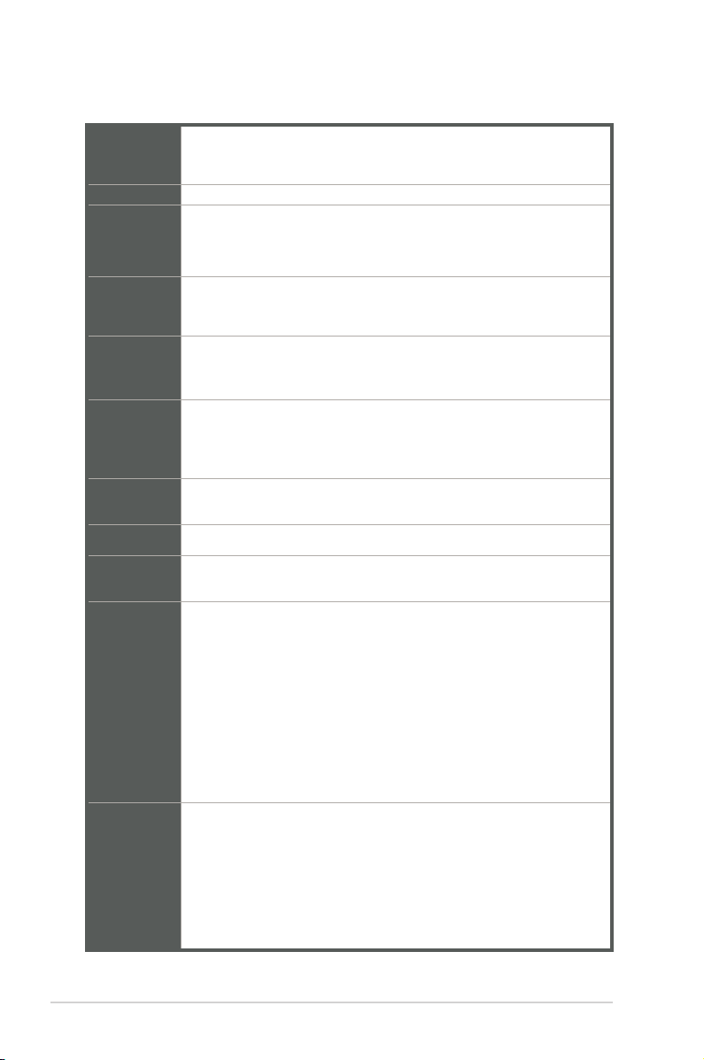
1.3 Specications
Intel® socket 1151 for 9th/8th Gen Intel® Core™ i7/ i5/ i3, Pentium®, and
CPU
Chipset Intel® H310 Chipset
Memory
Graphics
Expansion
slots
USB
Serial port
LAN
Audio
Rear panel
I/O ports
Front panel
I/O ports
Celeron® processors
Supports Intel® 14nm CPU
2 x DIMM, max.32GB, DDR4 2666*/2400/2133 MHz, non-ECC, un-
buffered memory
* DDR4 2666MHz and higher memory modules will run at max. 2666MHz on Intel® 8th Gen.
6 core or higher processors.
Multi-VGA output support: 1x DVI-D port, 1x D-Sub port with max.
resolution of 1920 x 1200 @60Hz
Supports up to 2 displays simultaneously
1 x PCI Express 3.0/2.0 x16 slot
2 x PCI Express 2.0 x1 slots
1 x PCI slot
- 4 x USB 3.2 Gen 1 ports (2 ports at the mid-board; 2 ports at the
rear panel)
- 6 x USB 2.0/1.1 ports (2 ports at the mid-board; 4 ports at the rear
panel)
1 x COM port (RS232)
1 x COM connector (RS232)
1X RJ45 Connector (1 x RTL8111H Gb LAN)
Realtek® ALC887-VD2 8-channel High Denition Audio CODEC
3 X Audio Jacks
2 x USB 3.2 Gen 1 ports
4 x USB 2.0/1.1 ports
1 x D-Sub port
1 x DVI-D port
1 x COM port (RS232)
3 x Audio jacks support 8-channel audio output
1 x LAN (RJ45) port
1 x P/S2 keyboard port
1 x P/S2 mouse port
1 x USB 3.2 Gen 1 connector supports additional 2 USB 3.2 Gen 1 ports
1 x USB 2.0/1.1 connector supports additional 2 USB 2.0/1.1 ports
1 x M.2 Socket 3 with M Key, Type 2260/2280 stroage devices support
(both SATA & PCIe x2 mode)
4 x SATA 6.0Gb/s connectors
1 x 4-pin CPU Fan connector
1 x 4-pin Chassis Fan connector for PWM & DC mode
1-2
(continued on the next page)
H310M-IM-A
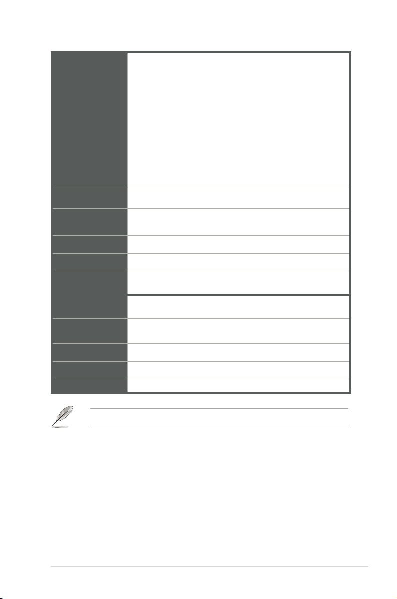
1 x Front panel audio connector(AAFP)
1 x System panel connector
1 x 24-pin ATX power connector
1 x 4-pin ATX power connector
Front panel I/O
ports
TPM 1 x TPM header (LPC)
1 x Chassis Intrusion connector
1 x Speaker connector
1 x COM connector(RS232)
1 x Parallel connector
1 x Clear CMOS header
1 x 14-1 pin TPM header
1 x LPC Debug header
BIOS features
Manageability WfM 2.0, DMI 2.0, WOL by PME
Watch dog timer Yes
Power
requirement
Operation
Temperature
Non-Operation
Temperature
Relative Humidity 0%~85%
OS support Linux, Windows® 10 (64-bit)
Form Factor Micro ATX Form Factor, 9.6”x 7.6” (24.4cm x 19.3cm)
NOTE: Specications are subject to change without notice.
128 Mb Flash ROM, UEFI AMI BIOS, PnP, SM BIOS 3.1, ACPI
6.1, Multi-language BIOS
ATX Mode
0~60°C
-40~85°C
Chapter 1: General information
1-3
Chapter 2
Motherboard information
2.1 Before you proceed
Take note of the following precautions before you install motherboard components
or change any motherboard settings.
CAUTION!
• Unplug the power cord from the wall socket before touching any
component.
• Before handling components, use a grounded wrist strap or touch a safely
grounded object or a metal object, such as the power supply case, to avoid
damaging them due to static electricity.
• Hold components by the edges to avoid touching the ICs on them.
• Whenever you uninstall any component, place it on a grounded antistatic
pad or in the bag that came with the component.
• Before you install or remove any component, always remove the AC power
by unplugging the power cord from the power outlet. Failure to do so may
cause severe damage to the motherboard, peripherals, or components.
2-1
Chapter 2: Motherboard information
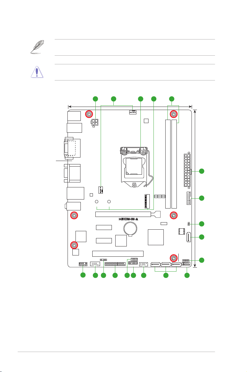
2.2 Motherboard layout
NOTE: Place six screws into the holes indicated by circles to secure the
motherboard to the chassis.
CAUTION! Do not overtighten the screws! Doing so can damage the
motherboard.
Place this side
towards the rear
of the chassis
KBMS
USB5-8
DVI
COM1
LAN_U32G1_34
AUDIO
Super
ALC
887
AAFP
1 52 43
ATX12V
VGA
CHA_FAN
RTL
8111H
2280 2260
PCIEX1_1
I/O
COM2
PCIEX1_2
CHASSIS
17
19.3cm(7.6in)
PCIEX16
ASM
1083
PCI
LPT
CPU_FAN
LGA1151
BATTERY
TPM
DIGI
+VRM
1
1
EATXPWR
DDR4 DIMM_B1* (64bit, 288-pin module)
DDR4 DIMM_A1* (64bit,288-pin module)
M.2(SOCKET3)
PCIE SATA IRST
X2 V X
M.2(SOCKET3)
ASM1480
128Mb
®
Intel
H310
LPC DEBUG
USB914
1213141516
BIOS
SATA6G_2
SATA6G_3SATA6G_4
8 1011
SPEAKER
F_PANEL
U32G1_12
CLRTC
SATA6G_1
24.4cm(9.6in)
1
6
1
7
1
8
1
9
H310M-IM-A
2-2
Connectors/Jumpers/Slots
1. ATX power connectors (24-pin EATXPWR, 4-pin ATX12V) 2-19
2. CPU and chassis fan connectors (4-pin CPU_FAN, 4-pin CHA_FAN) 2-16
3. Intel® LGA1151 CPU socket 2-4
4. M.2 socket 3 2-18
5. DDR4 DIMM slots 2-9
6. USB 3.2 Gen 1 connector (20-1 pin U32G1_12) 2-14
7. Clear RTC RAM (2-pin CLRTC) 2-11
8. Serial ATA 6.0Gb/s connectors (7-pin SATA6G_1-4) 2-20
9. Speaker connector (4-pin SPEAKER) 2-15
10. System panel connector (10-1 pin F_PANEL) 2-17
11. USB 2.0 connector (10-pin USB914) 2-15
12. TPM connector (14-1 pin TPM) 2-14
13. LPC debug header 2-16
14. LPT connector 2-20
15. Chassis Intrusion header 2-11
16. Serial port connector (10-1 pin COM2) 2-18
17. Front panel audio connector (10-1 pin AAFP) 2-19
Page
2-3
Chapter 2: Motherboard information
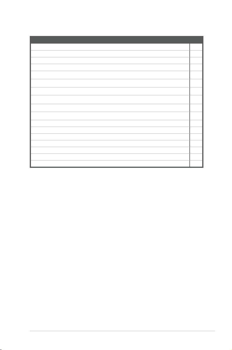
2.3 Central Processing Unit (CPU)
The motherboard comes with a surface mount LGA1151 socket designed for the
Intel® 9th/8th Generation Core™ i7 / Core™ i5 / Core™ i3, Pentium
processors.
H310M-IM-A CPU socket LGA1151
IMPORTANT: Unplug all power cables before installing the CPU.
CAUTION!
• Upon purchase of the motherboard, ensure that the PnP cap is on
the socket and the socket contacts are not bent. Contact your retailer
immediately if the PnP cap is missing, or if you see any damage to the
PnP cap/socket contacts/motherboard components. The manufacturer will
shoulder the cost of repair only if the damage is shipment/transit-related.
• Keep the cap after installing the motherboard. The manufacturer will
process Return Merchandise Authorization (RMA) requests only if the
motherboard comes with the cap on the LGA1151 socket.
• The product warranty does not cover damage to the socket contacts
resulting from incorrect CPU installation/removal, or misplacement/loss/
incorrect removal of the PnP cap.
®
, and Celeron®
H310M-IM-A
2-4
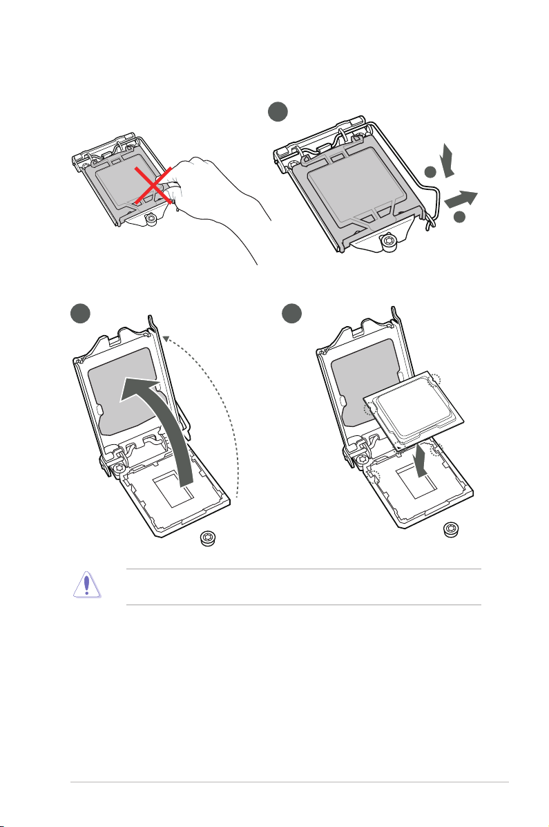
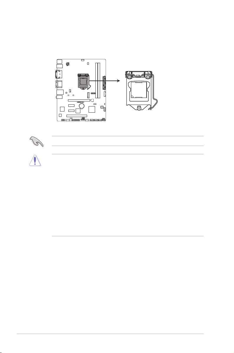
2.3.1 Installing the CPU
2 3
1
A
B
2-5
CAUTION! LGA1156 CPU is not compatible with the LGA1151 socket. DO
NOT install an LGA1156 CPU on the LGA1151 socket.
Chapter 2: Motherboard information
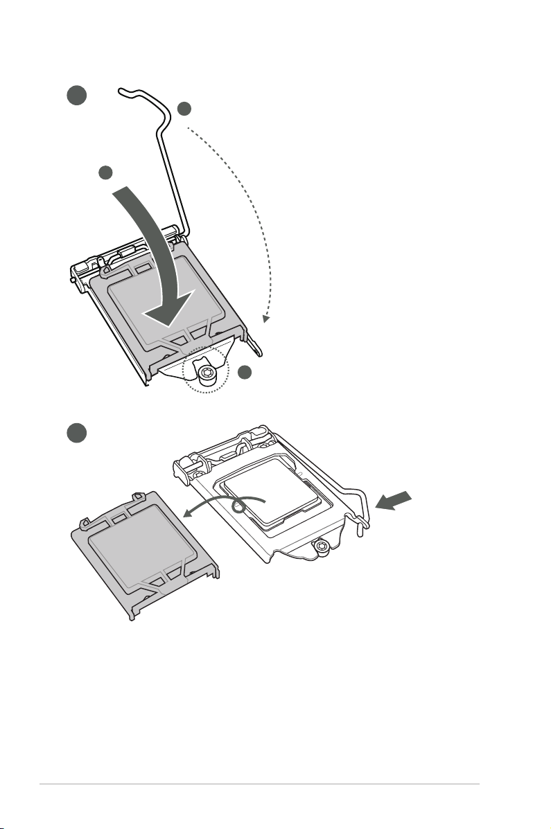
4
C
A
B
5
H310M-IM-A
2-6
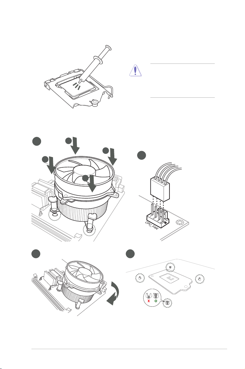
2.3.2 CPU heatsink and fan assembly installation
CAUTION! Apply the Thermal
Interface Material to the CPU
heatsink and CPU before you
install the heatsink and fan if
necessary.
To install the CPU heatsink and fan assembly
1
A
B
B
A
3 4
2
2-7
Chapter 2: Motherboard information
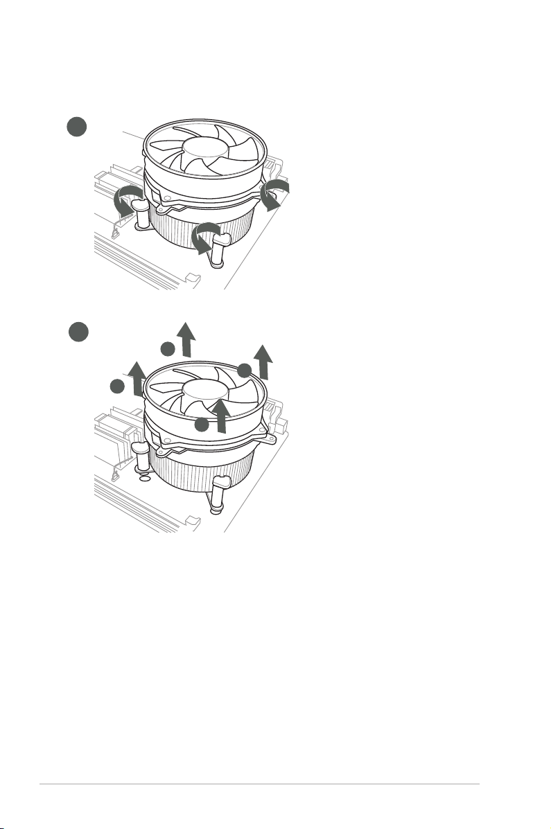
To uninstall the CPU heatsink and fan assembly
1
2
A
B
B
A
H310M-IM-A
2-8
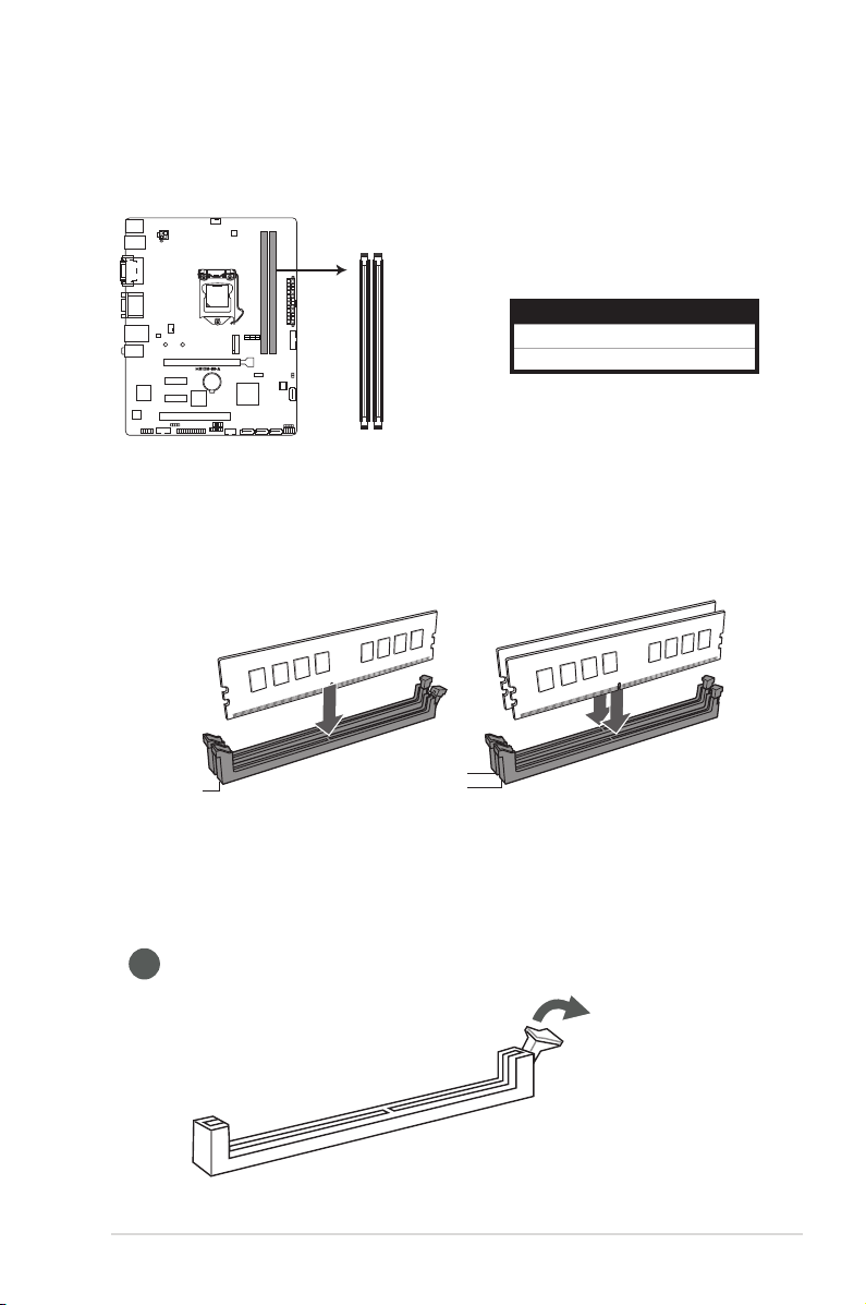
2.4 System memory
DDR4 DIMM sockets
This motherboard comes with two Double Data Rate 4 (DDR4) Dual Inline Memory Module
(DIMM) sockets. The gure below illustrates the location of the DDR4 DIMM sockets:
DIMM_B1*
DIMM_A1*
Channel Sockets
Channel A DIMM_A1*
Channel B DIMM_B1*
H310M-IM-A 288-pin
Recommendedmemoryconguration
DIMM_A1*
Installing a DIMM
1
2-9
DIMM_B1*
DIMM_A1*
Chapter 2: Motherboard information
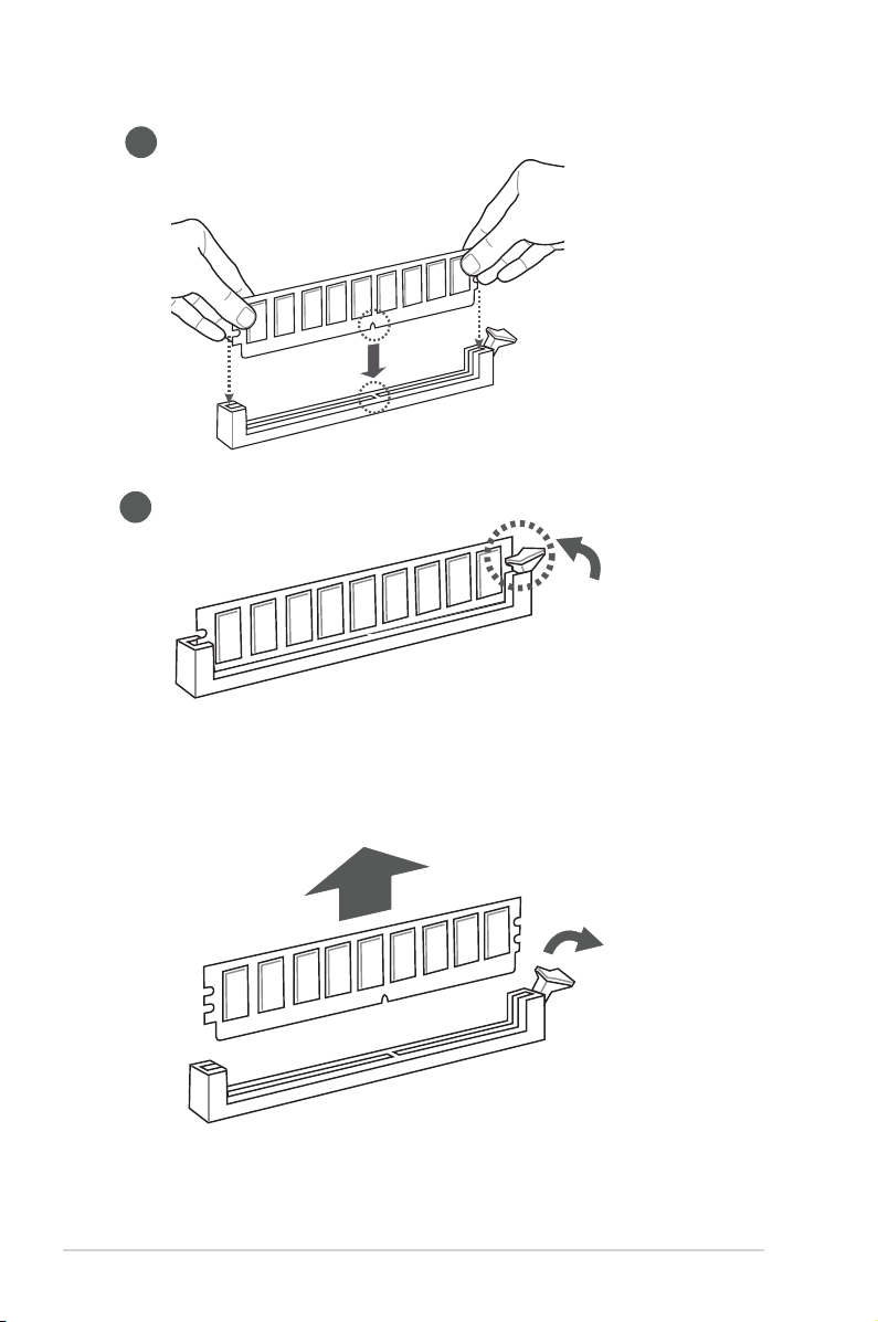
2
3
To remove a DIMM
H310M-IM-A
2-10
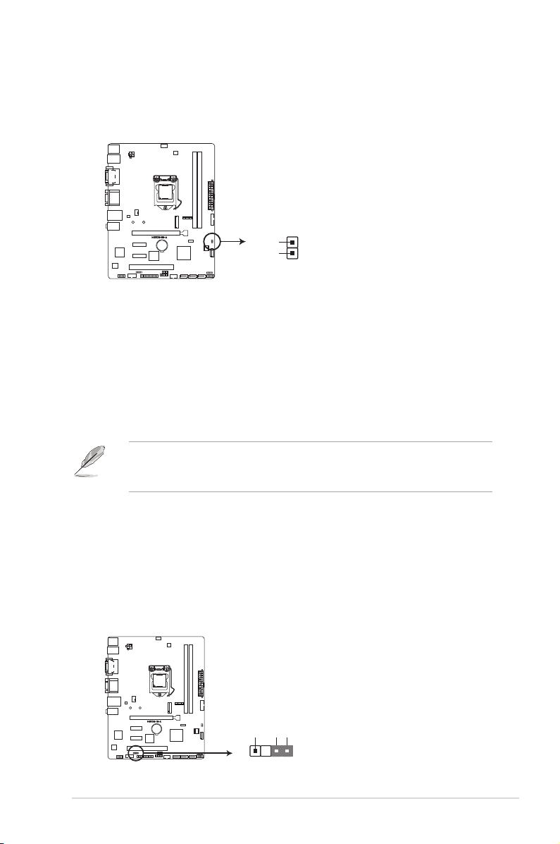
2.5 Jumpers
1. Clear RTC RAM (2-pin CLRTC)
This header allows you to clear the CMOS RTC RAM data of the system
setup information such as date, time, and system passwords.
CLRTC
GND
+3V_BAT
H310M-IM-A Clear RTC RAM
To erase the RTC RAM:
1. Turn OFF the computer and unplug the power cord.
2. Use a metal object such as a screwdriver to short the two pins.
3. Plug the power cord and turn ON the computer.
4. Hold down the <Del> key during the boot process and enter BIOS setup
to re-enter data.
NOTE: If the steps above do not help, remove the onboard battery and move
the jumper again to clear the CMOS RTC RAM data. After clearing the CMOS,
reinstall the battery.
PIN 1
2. Chassis intrusion jumper (4-1 pin CHASSIS)
This connector is for a chassis-mounted intrusion detection sensor or switch.
Connect one end of the chassis intrusion sensor or switch cable to this
connector. The chassis intrusion sensor or switch sends a high-level signal to
this connector when a chassis component is removed or replaced. The signal
is then generated as a chassis intrusion event.
Move the jumper cap to pins 1-2 when you intend to use the chassis intrusion
detection feature.
CHASSIS
+5VSB_MB
Chassis Signal
GND
PIN 1
H310M-IM-A Chassis intrusion connector
2-11
Chapter 2: Motherboard information
2.6 Connectors
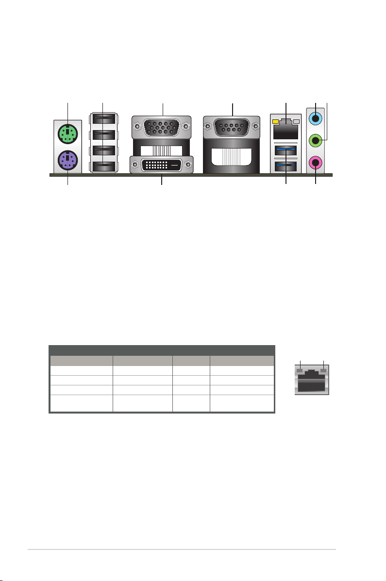
2.6.1 Rear panel connectors
1 2 5
3 4
10
6 7
911
8
1. PS/2 Mouse port (green). This port is for a PS/2 mouse.
2. USB 2.0 ports. These 4-pin Universal Serial Bus (USB) ports are for USB
2.0/1.1 devices.
3. D-Sub port. This 15-pin port is for a D-Sub monitor or other D-Sub
compatible devices.
4. Serial port connector (COM). This port connect a modem, or other devices
that conform with serial specication.
5. LAN (RJ-45) ports. These ports allow Gigabit connection to a Local Area
Network (LAN) through a network hub.
LAN port LED indications
Activity/Link LED Speed LED
Status Description Status Description
Off No link OFF 10Mbps connection
Orange Linked ORANGE 100Mbps connection
Orange (Blinking) Data activity GREEN 1Gbps connection
Orange (Blinking
then steady)
Ready to wake up
from S5 mode
Activity Link
LED
LAN port
Speed
LED
6. Line In port (light blue). This port connects to the tape, CD, DVD player, or
other audio sources.
7. Line Out port (lime). This port connects to a headphone or a speaker. In
the 4.1, 5.1and 7.1-channel congurations, the function of this port becomes
Front Speaker Out.
H310M-IM-A
2-12
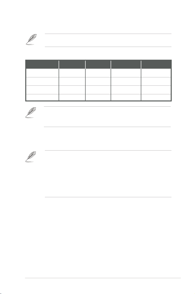
8. Microphone port (pink). This port connects to a microphone.
Refer to the audio conguration table for the function of the audio ports in 2.1,
4.1, 5.1, or 7.1-channel conguration.
Audio2.1,4.1,5.1or7.1-channelconguration
Port
Line Ourt (Rear
panel)
MIC(Rear panel) MIC
Headphone (Front
panel)
MIC (Front panel) MIC MIC MIC Side Speaker Out
Headset
2.1-channel
Front Speaker
Out
Headphone Headphone
4.1-channel 5.1-channel 7.1-channel
Front Speaker
Out
Rear Speaker
Out
Front Speaker Out Front Speaker Out
Rear Speaker Out Rear Speaker Out
Center/Subwoofer
Speaker Out
Center/Subwoofer
Speaker Out
Tocongurea7.1-channelaudiooutput:
Use a chassis with HD audio module in the front panel to support a
7.1-channel audio output.
9. USB 3.2 Gen 1 (up to 5Gbps) ports. These 9-pin Universal Serial Bus
(USB) ports are for USB 3.2 Gen 1 devices.
• USB 3.2 Gen 1 devices can only be used for data storage.
• We strongly recommend that you connect USB 3.2 Gen 1 devices to USB
3.2 Gen 1 ports for faster and better performance from your USB 3.2 Gen 1
devices.
• Due to the design of the Intel® 300 series chipset, all USB devices
connected to the USB 2.0 and USB 3.2 Gen 1 ports are controlled by the
xHCI controller. Some legacy USB devices must update their rmware for
better compatibility.
10. DVI-D port. This port is for any DVI-D compatible device.
11. PS/2 Keyboard port (purple). This port is for a PS/2 keyboard.
2-13
Chapter 2: Motherboard information
 Loading...