

ASUS g1s Service Manual
Disassembly procedure
A
Chapter
Disassembly Procedure
Please follow the information provided in this section to perform the complete
disassembly procedure of the notebook. Be sure to use proper tools described
before.
SUS G1S Series Notebook consists of various modules. This chapter describes the
procedures for the complete notebook disassembly. In addition, in between procedures,
the detailed disassembly procedure of individual modules will be provided for your service
needs.
The disassembly procedure consists of the following steps:
• Battery Module
• CPU Module
• Memory Module
• HDD Module
• Optical Drive Module
• Keyboard Module
• Top Case Module
• LCD Module
• Motherboard Module
• WLAN Module
2 - 1
BATTERY
CPU MODULE
REMOVAL
Disassembly procedure
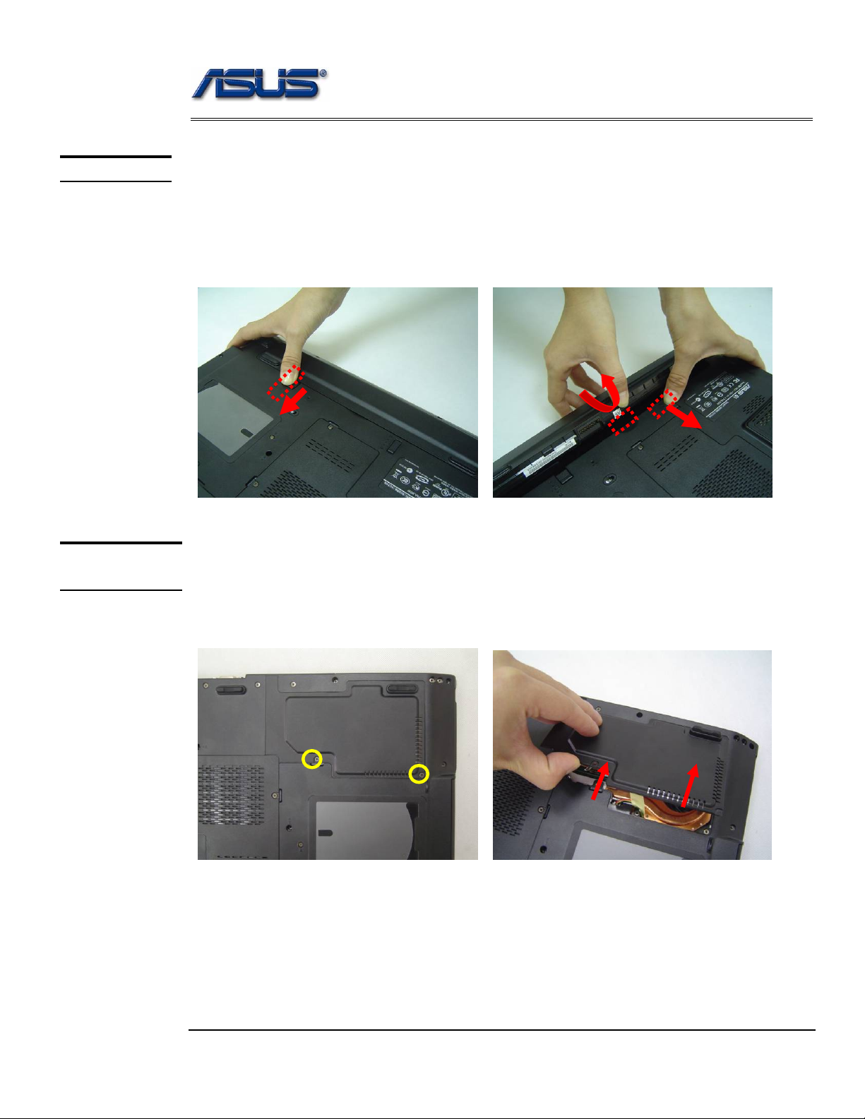
Battery Module
The illustration below shows how to remove the battery module.
Remove battery module
1.Slide the battery latch 1 to open battery lock
2.Slide the battery latch 2 and pull the whole battery away from the system.
1
3
2
3
CPU Module
The illustrations below show ho w to remove the CPU module from the notebook.
Replacement CPU
1. Remove 2 screws (M2*4) and take the CPU door away.
M2*4
2 - 2
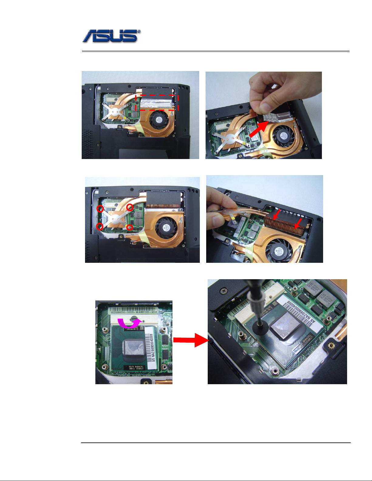
Disassembly procedure
2. Remove the Mylar.
3. Remove 4 screws (M2*5) aside the CPU. And take away the heat sink..
M2*5
4. Turn the non-removable screw here 180 degrees counter-clockwise to loosen the CPU.
2 - 3
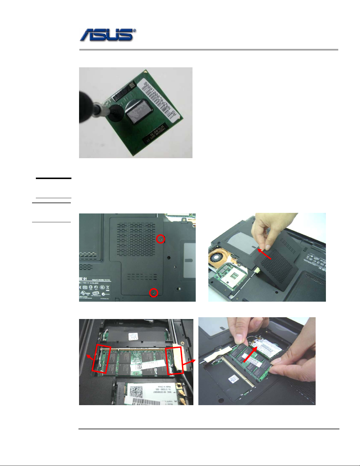
Disassembly procedure
5. Squeeze the vacuum handling pump and use it to lift the CPU away.
MEMORY
MODULE
MEMORY
REMOVAL
Memory Module
The illustration shows how to remove the memory module form the notebook.
Removing Memory module
1. Remove 2 screws on the memory cover and then remove the cover.
2. Unlock two latches to pop up the memory at 45 angles then pull out the memory at that angle.
2 - 4
Disassembly procedure
WLAN
MODULE
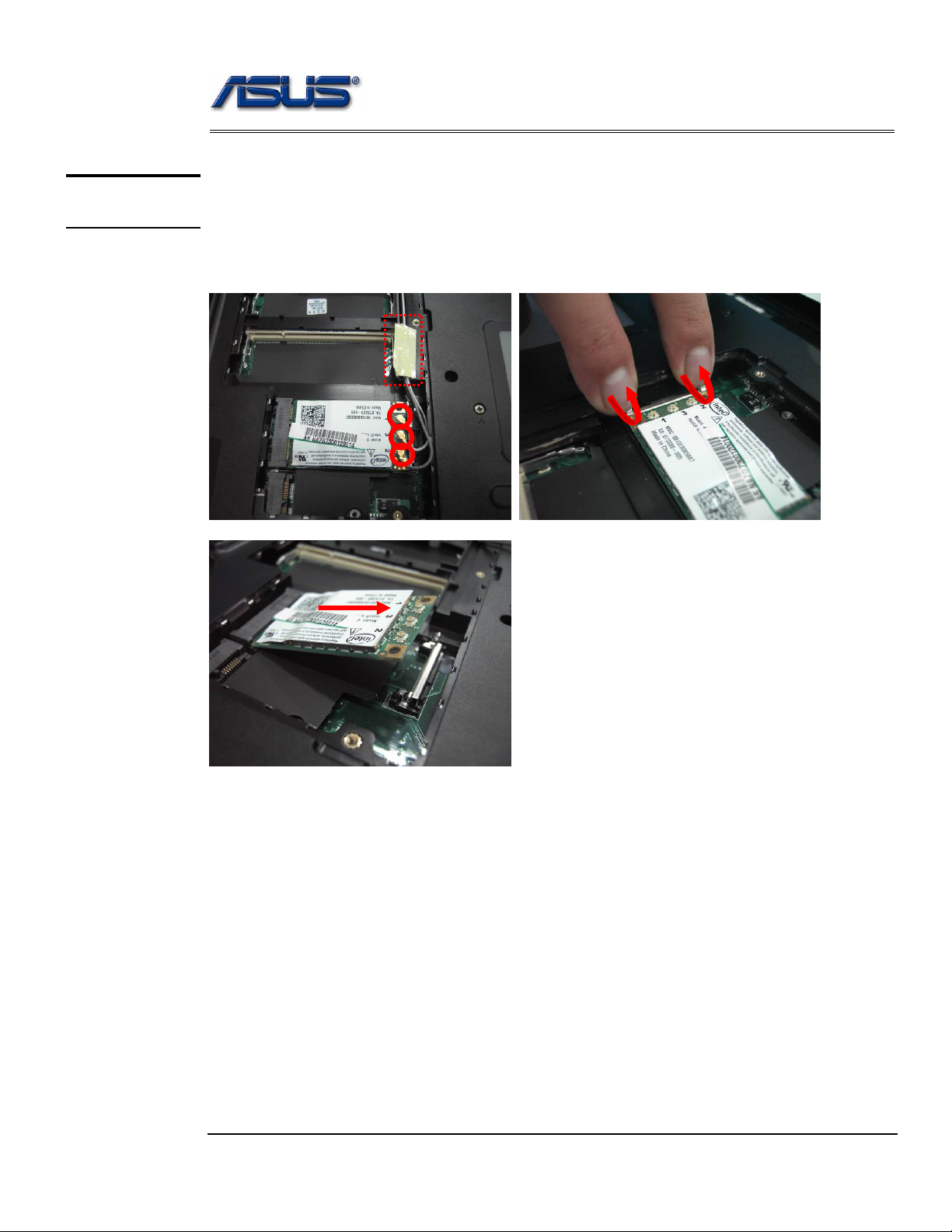
WLAN Module
The illustrations below show ho w to remove the WLAN modul e from the notebo ok.
Remove WLAN module
1. Disconnect 3 antenna cables, remove 1 piece of tape and remove the antennas out of cable guide;
then unlock two latch and take WLAN out of syst em;
2 - 5
Disassembly procedure
HDD
MODULE
HDD
MODULE
REMOVAL
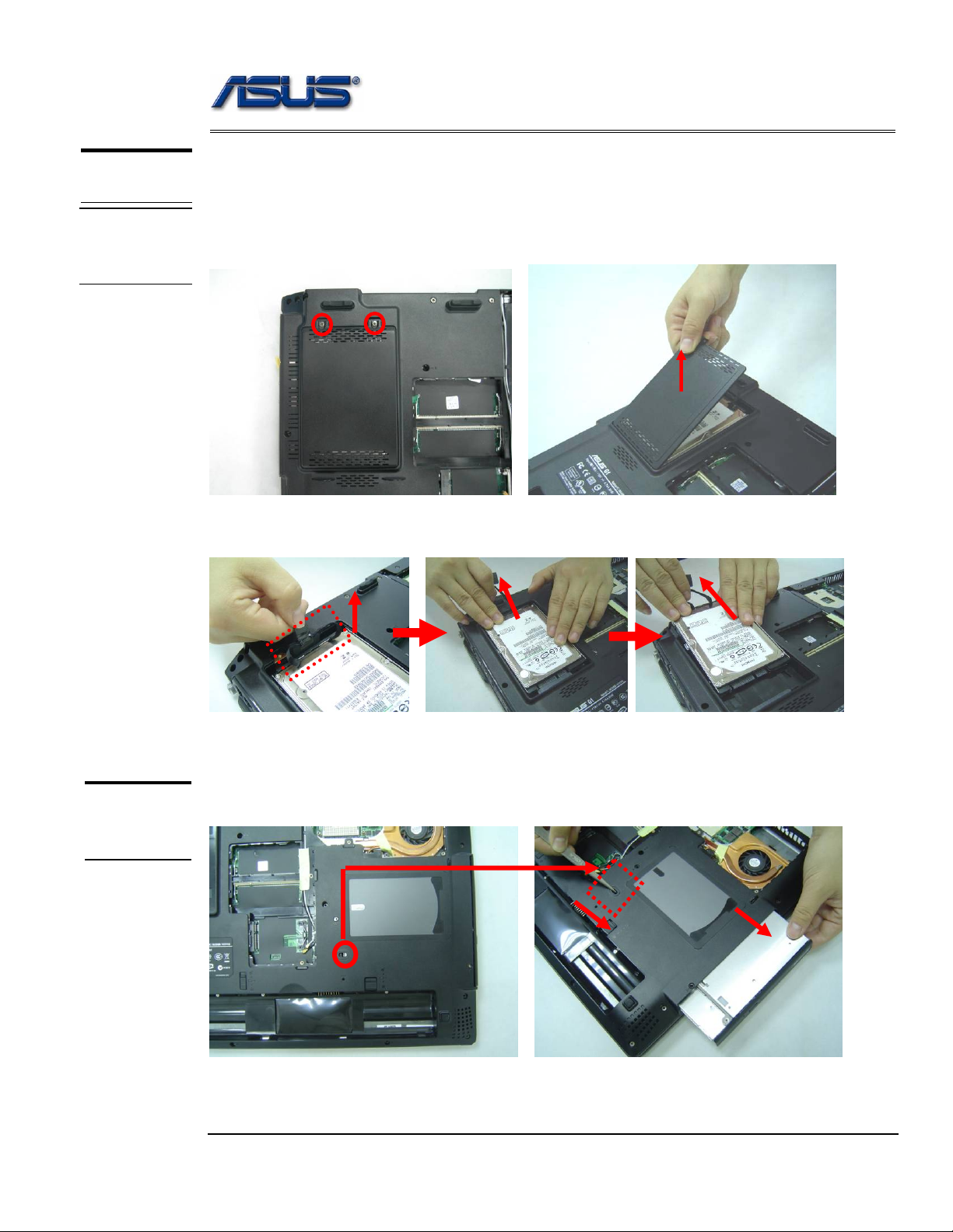
HDD Module
The illustrations below show ho w to remove the HDD m odule from the notebo ok.
Removing HDD Module
1. Remove 2 screws (M2*5) here, open HDD door by the tweezers and then take away the HDD
door.
2. Remove the sponge and pull the hard disk module toward the direction of the arrow and lift it up
and take it out.
OPTICAL
DRIVE
REMOVAL
Optical Drive Module
1. Unlock and hold the latch, and remove the ODD module.
2 - 6
Disassembly procedure
KEYBOARD
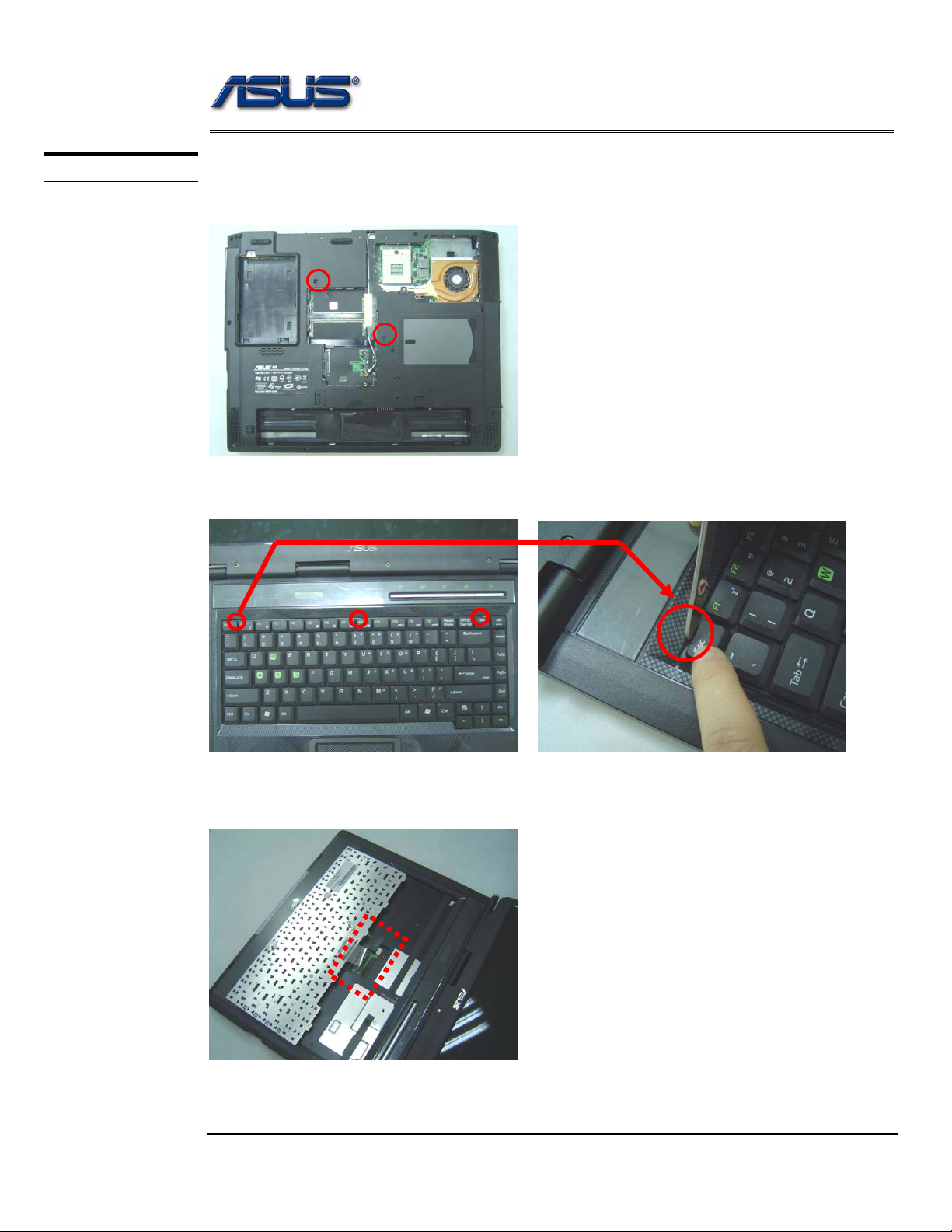
Keyboard Module
The illustration of below shows how to remove th e keyboard
Removing Keyboard
1. Remove 2 screw (M2*5) here, and then turn over the notebook.
2. Push the 3 latches in (F1, F8, Ins) with a pair of tweezers or a single-slotted screwdriver
and lift the keyboard plate up.
3. Lay the keyboard down over the Top case. *Do not remove the keyboard yet.
The keyboard cable is still attached.
2 - 7
Disassembly procedure
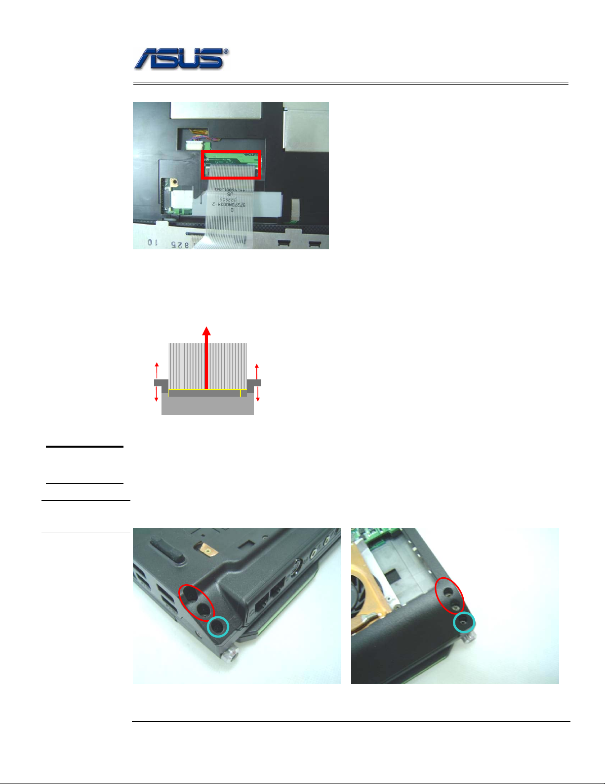
4. Disconnect the FPC connector by a pair of tweezers and then remove the keypad plate.
Removing Keyboard Cable
1. Use a flexible connector tool to unlock the cable connector on both ends (no. 1).
2. Carefully pull out the keyboard cable (no. 2) with a pair of tweezers.
3. Lock the connector (no. 3) again to avoid possible breakage.
2. Cable out
1. Unlock
3.
1. Unlock
3.
TOP CASE
MODULE
T op Case Module
The illustrations below show how to disassemble and remove the top case module of the notebook.
The module contains the top case itself.
TOP CASE
REMOVAL
Removing Top Case Module
1. Remove 6 screws (M2*8; M2*5) here
2 - 8
 Loading...