

Page 1

E915
ADSL Modem / Router
User’s Guide
Page 2

Copyright
No part of this manual, including the products and software described in it, may be
reproduced, transmitted, transcribed, stored in a retrieval system, or translated into
any language in any form or by any means, except documentation kept by the purchaser for backup purposes, without the express written permission of The Manufacturer.
THE MANUFACTURER PROVIDES THIS MANUAL “AS IS” WITHOUT
WARRANTY OF ANY KIND, EITHER EXPRESS OR IMPLIED, INCLUDING
BUT NOT LIMITED TO THE IMPLIED WARRANTIES OR CONDITIONS OF
MERCHANTABILITY OR FITNESS FOR A PARTICULAR PURPOSE. IN NO
EVENT SHALL THE MANUFACTURER, ITS DIRECTORS, OFFICERS, EMPLOYEES OR AGENTS BE LIABLE FOR ANY INDIRECT, SPECIAL, INCIDENT AL, OR CONSEQUENTIAL DAMAGES (INCLUDING DAMAGES FOR
LOSS OF PROFITS, LOSS OF BUSINESS, LOSS OF USE OR DATA, INTERRUPTION OF BUSINESS AND THE LIKE), EVEN IF THE MANUF ACTURER
HAS BEEN ADVISED OF THE POSSIBILITY OF SUCH DAMAGES ARISING
FROM ANY DEFECT OR ERROR IN THIS MANUAL OR PRODUCT.
Product warranty or service will not be extended if: (1) the product is repaired,
modified or altered, unless such repair, modification of alteration is authorized in
writing by The Manufacturer; or (2) the serial number of the product is defaced or
missing.
Products and corporate names appearing in this manual may or may not be registered trademarks or copyrights of their respective companies, and are used only for
identification or explanation and to the owners’ benefit, without intent to infringe.
SPECIFICA TIONS AND INFORMATION CONT AINED IN THIS MANUAL ARE
FURNISHED FOR INFORMATIONAL USE ONLY, AND ARE SUBJECT TO
CHANGE AT ANY TIME WITHOUT NOTICE, AND SHOULD NOT BE CONSTRUED AS A COMMITMENT BY THE MANUF ACTURER. THE MANUF ACTURER ASSUMES NO RESPONSIBILITY OR LIABILITY FOR ANY ERRORS
OR INACCURACIES THAT MAY APPEAR IN THIS MANUAL, INCLUDING
THE PRODUCTS AND SOFTWARE DESCRIBED IN IT.
Copyright © 2001 The Manufacturer. All Rights Reserved.
Product Name: ADSL Router
Manual Revision: 1.10 E915
Release Date: Nov 2001
2
ADSL Modem/Router User’s Guide
Page 3

CONTENTS
1. Introduction ............................................................................. 5
1.1 Overview .......................................................................................... 5
1.2 Features........................................................................................... 5
1.3 System Requirements...................................................................... 5
2. Installation ............................................................................... 6
2.1 TCP/IP Settings ............................................................................... 6
2.1.1 Windows Me....................................................................... 6
2.1.2 Windows 2000.................................................................... 6
2.2 V erifying TCP/IP Settings................................................................. 7
2.2.1 Windows Me....................................................................... 7
2.2.1 Windows 2000.................................................................... 7
2.3 Installing the ADSL Modem/Router.................................................. 8
2.3.1 Front Panel......................................................................... 8
2.3.2 Rear Panel ......................................................................... 8
2.4 Connecting the ADSL Modem/Router.............................................. 9
2.5 Powering Up .................................................................................. 10
3. Management Consoles ......................................................... 11
3.1 Accessing the Web Console .......................................................... 11
3.2 Accessing the User Console.......................................................... 12
3.2.1 COM Port Configuration ................................................... 12
3.2.2 Telnet Configuration ......................................................... 13
3.3 Console Features........................................................................... 13
4. Basic Configuration .............................................................. 15
4.1 Set Channel Configuration............................................................. 15
4.1.1 MPoA Bridged .................................................................. 16
4.1.2 MPoA Routed ................................................................... 18
4.1.3 IPoA Routed ..................................................................... 20
4.1.4 PPPoA Routed ................................................................. 22
4.1.5 PPPoE Relay.................................................................... 24
4.1.6 PPPoE Routed ................................................................. 26
4.1.7 MPoA Routed over MAC .................................................. 28
4.2 Set Ethernet Configuration............................................................. 30
4.3 Routing Table Maintenance ........................................................... 31
5. Software Upgrade ................................................................. 32
5.1 Using ADSL Modem Upgrade Utility .............................................. 32
5.2 Using BootP / TFTP Servers.......................................................... 33
Appendix.................................................................................... 37
USB Combo Series ................................................................................. 37
Mounting the USB Port ........................................................................... 38
Installing USB Drivers ............................................................................. 40
ADSL-Related Acronyms ........................................................................ 47
ADSL Modem/Router User’s Guide 3
Page 4

Contents
4
ADSL Modem/Router User’s Guide
Page 5

1. Introduction
1.1 Overview
Thank you for purchasing this ADSL Modem/Router. This ADSL Modem/Router
delivers the highest performance in Asymmetric Digital Subscriber Line technology, allowing you to simultaneously enjoy telephone and Internet service using
existing copper phone lines. Ideal for home and small business users, this easy-touse ADSL Modem/Router offers reliable connectivity and remarkable data transfer
rates. Once the ADSL Modem/Router is online, you can enjoy real-time 3D animation, video conferencing, or perform other data intensive operations.
1.2 Features
Software Features
• Supports RFC 2364 protocol (PPP over ATM), RFC 1483 encapsulation (multiple
protocol over ATM AAL5), RFC 2516 protocol (PPP over Ethernet), and RFC 1577
protocol (classical IP over ATM)
• Firmware upgrade and configuration restoration over TFTP
• Supports DHCP Server, DHCP Relay, NAT, IP Filter, IGMP Proxy, RIP, DNS Relay,
ATM OAM, ATM QoS.
• User Maintenance
1.3 System Requirements
The ADSL Modem/Router requires that your computer has an Ethernet port with
TCP/IP installed.
ADSL Modem/Router User’s Guide 5
Page 6
2. Installation
2.1 TCP/IP Settings
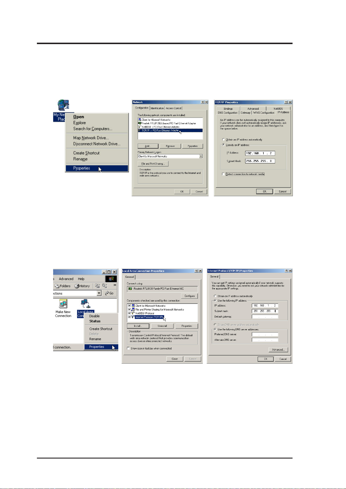
2.1.1 Windows Me
Right-click “My Network Places” on the desktop and select Properties. Doubleclick TCP/IP and specify 192.168.1.2 as the IP Address and 255.255.255.0 as the
Subnet Mask.
2.1.2 Windows 2000
Right-click “My Network Places” on the desktop and select Properties. Right-click
Local Area Connection and select Properties. Double-click TCP/IP and specify
192.168.1.2 as the IP Address and 255.255.255.0 as the Subnet Mask.
6
ADSL Modem/Router User’s Guide
Page 7
2. Installation
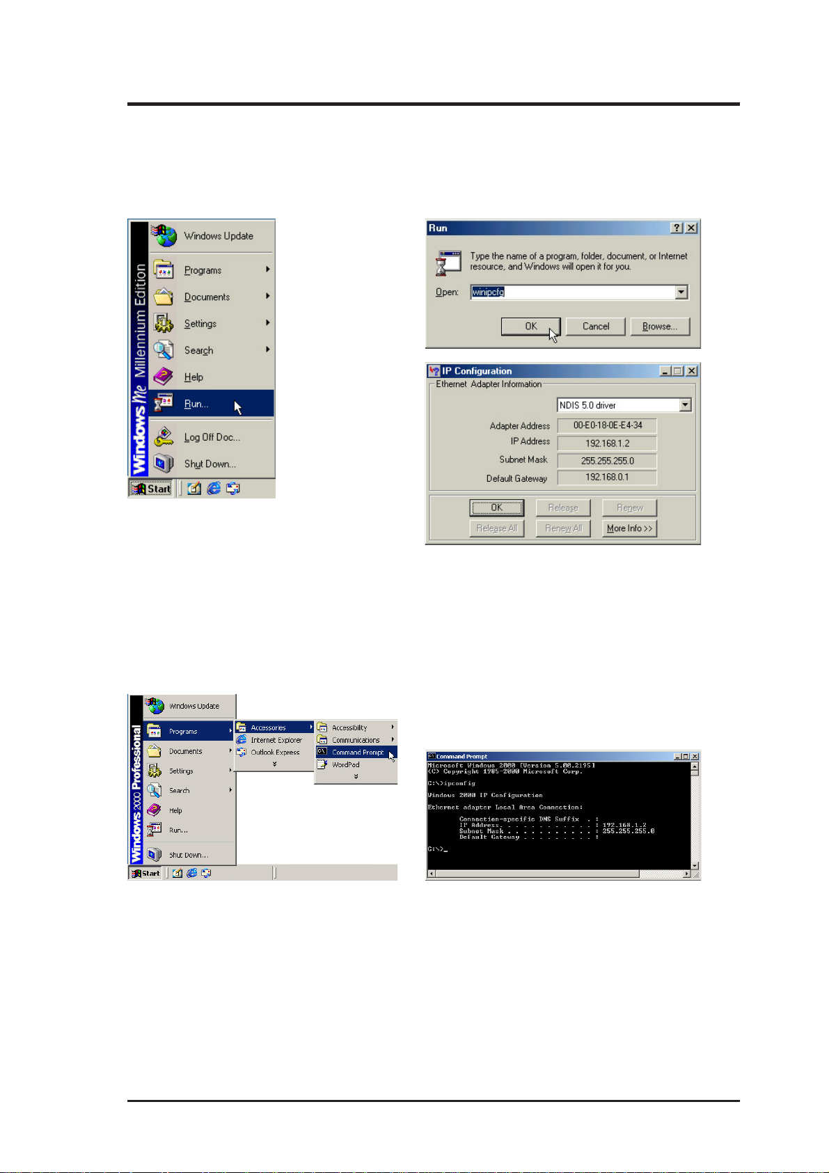
2.2 Verifying TCP/IP Settings
2.2.1 Windows Me
Type winipcfg in the Run command and your IP information will be shown.
2.2.1 Windows 2000
Type ipconfig in the Command Prompt and your IP information will be shown.
ADSL Modem/Router User’s Guide 7
Page 8
2. Installation
2.3 Installing the ADSL Modem/Router
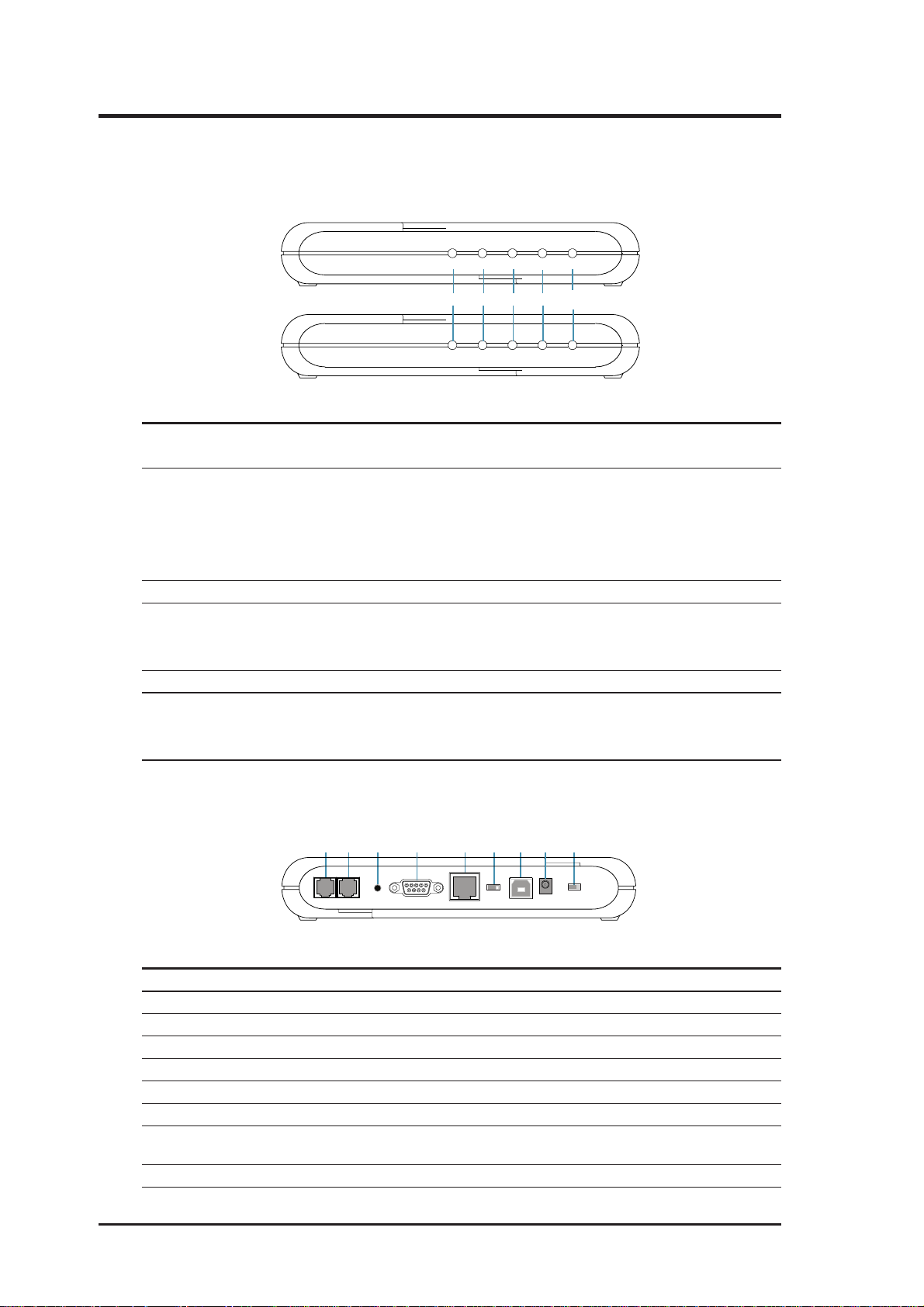
2.3.1 Front Panel
ADSL Modem
ADSL Modem (USB Combo)
POWER STATUS TESTLINE PC
123
POWER STATUS LINE PC
5a
4
5b
USB
LED Indicator State Description
1. Power LED ON Modem is powered ON
OFF Modem is powered OFF
2. Status LED ON “Showtime”—successful connection between
(ADSL Line Status) ADSL modem and telephone company’s network
Flashing “Handshaking”—modem is trying to establish a
connection to telco’s network
OFF “Down”—ADSL line is inactivated
3. Line LED (WAN) Flashing Data transmitting between modem and telco’s network
4. PC Link LED (LAN) ON Successful connection between LAN and PC
(LAN Traffic LED) Flashing Data transmitting between LAN and PC
OFF No connection between LAN and PC*
5a.Test OFF Normal operation
5b.USB ON USB and PC connected successfully
Flashing Data transmitting between USB and PC
OFF No connection between USB & PC, or USB driver not ready
* Check if the Ethernet cable is properly connected and the HUB-PC switch is in the correct position.
2.3.2 Rear Panel
1 23 5 76 9
Line
Phone
LED Indicator Description
1. Line Connector RJ11 connector, connected to an ADSL network
2. Phone Port (optional) RJ11 connector, connected to telephone set
3. Reset Switch Restart the modem/router
4. Console Port 9-pin D-sub serial port for RS-232 console management
5. LAN Port RJ45 connector, connected to the user’s LAN
6. HUB-PC Switch (optional) Controls the modem to PC crossover function
7. USB Port (optional) Connects to computers without a LAN port
8. Power Input Jack Power input, power supply to modem/router
9. Power Switch (optional) Turns ON or OFF the modem/router
8
ADSL Modem/Router User’s Guide
4 8
Reset
Console
HUB PC
LAN
USB
Power
ON OFF
(must use the supplied power adapter)
Page 9
2. Installation
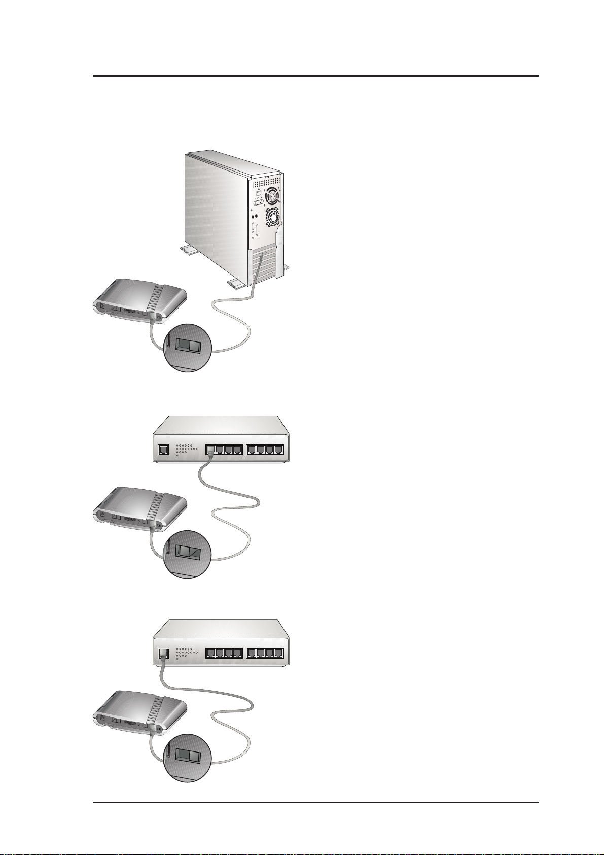
2.4 Connecting the ADSL Modem/Router
Example 1. Modem to PC
T o use the modem with a PC, move the HUBPC switch to the right (PC position).
HUB
PC
Example 2. Modem to Hub (Downlink)
To use the modem with an Ethernet hub’s
downlink port, move the HUB-PC switch to the
left (HUB position).
HUB
1234 5678UPLINK
PC
Example 3. Modem to Hub (Uplink)
To use the modem with an Ethernet hub’s
1234 5678UPLINK
uplink port, move the HUB-PC switch to the
right (PC position).
HUB
PC
ADSL Modem/Router User’s Guide 9
Page 10
2. Installation
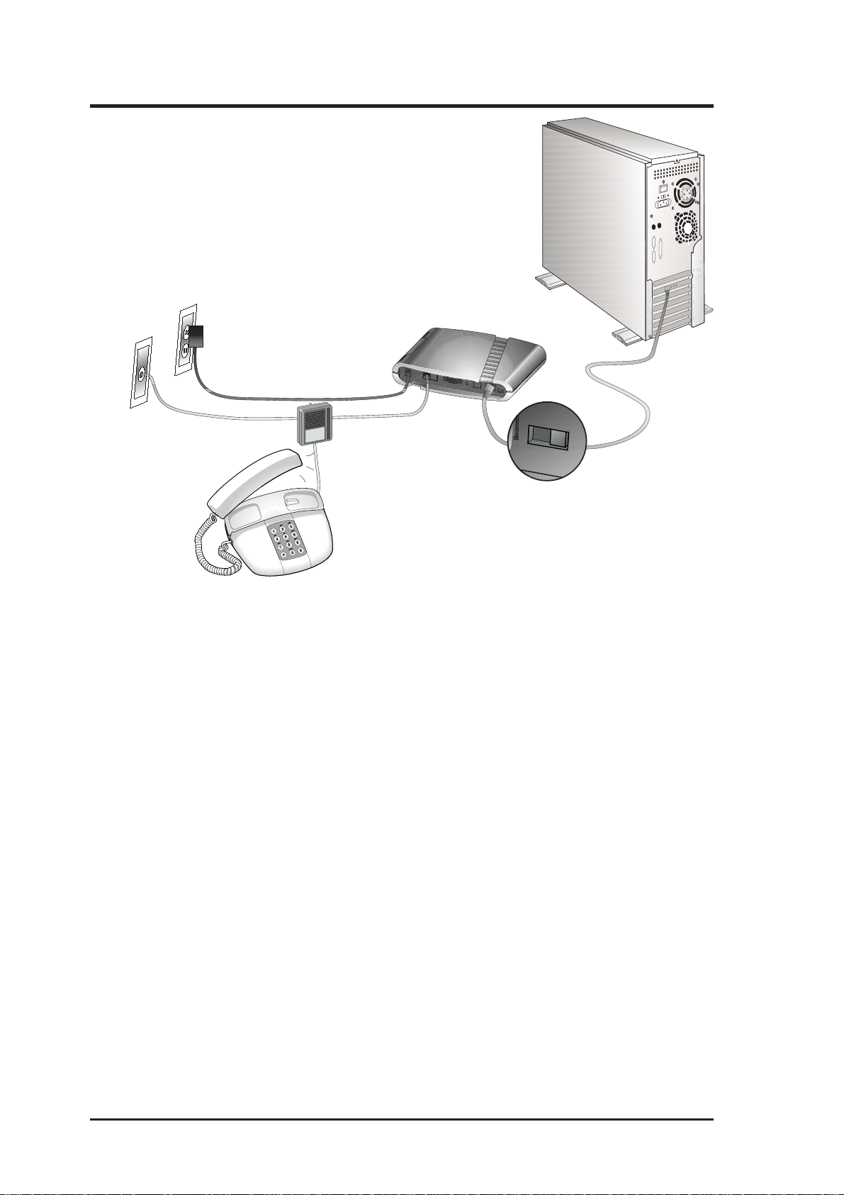
Example 4. ADSL Modem and Telephone
Power Outlet
LAN Cable
Telephone
Outlet
Power Adapter
Tel Splitter
T el Wire
HUB
PC
2.5 Powering Up
When all connections have been properly made and the power is ON, the ADSL
modem will automatically start the self-test and log on to your phone company’s
ADSL network. For new modems, go through the configuration as detailed in the
following section, and then you are all set and ready to enjoy Internet services at
high speeds!
10
ADSL Modem/Router User’s Guide
Page 11
3. Management Consoles
The management consoles provide basic configuration of the Ethernet port and 16
permanent virtual channels (PVC). The management consoles also provide advanced
network service settings and data trafftic monitoring.
NOTE: Screen displays may vary from this manual depending on model.
3.1 Accessing the Web Console
This modem/router provides convenient setup screens for quick configuration and
advanced configurations using the web console using the latest Microsoft
Explorer.
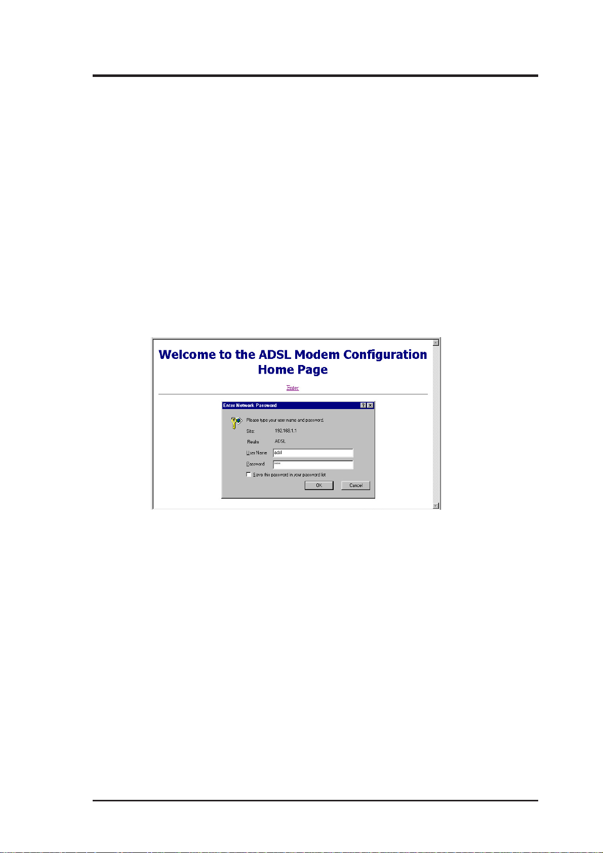
1. Start your web browser.
2. Type the Ethernet IP address of the modem/router on the address bar of the browser .
Default IP address is 192.168.1.1
3. The modem/router’s welcome page appears. Click Enter.
®
Internet
4. Type the user name (default: adsl) and password (default: adsl1234) when the Enter
Network Password dialog box appears and then click OK.
The web interface for the modem/router first displays a page (S/W Version ) showing the
modem/router’s Firmware Version and MAC Address.
NOTE: Your modem/router will now act as a web server sending the pages that
you requested or submit forms that you filled.
The first and the rest of the pages also provide links to the following functions:
• S/W Version: Displays the firmware version and MAC address of your modem/router .
• ADSL Line Status: Displays ADSL line status.
• Quick Setup Wizard: Guides you through network configuration process (LAN and
WAN configuration).
• Network Service: Provides network service maintenance options.
• Sys-Maintenance: Loads default settings and user management options.
• Reset Modem: Restarts the modem/router.
ADSL Modem/Router User’s Guide 11
Page 12
3. Management Consoles
3.2 Accessing the User Console
This section describes how to set up the different operation modes or monitor the
performance of your ADSL Modem/Router using the User Mode Console.
3.2.1 COM Port Configuration
For advanced modem management, use a serial cable to connect the Console port
on the ADSL modem to your PC’s empty COM port. Open a VT100 terminal emu-
lation program such as Windows’ HyperTerminal to configure the COM port.
COM Port Settings
Bit Rate: 9600 bps, Data Bits: 8, Parity Check: None, Stop Bit: 1, Flow Control: None
Starting Hyperterminal
In Windows, click Start, Programs, Accessories, Communications, and then se-
lect HyperTerminaI. When the HyperTerminal window appears, double click the
HyperTerminal icon to run it. If you cannot find it, add the program using Add/
Remove Programs in Control Panel.
12
ADSL Modem/Router User’s Guide
Page 13

3. Management Consoles
3.2.2 Telnet Configuration
The ADSL modem/router can be controlled by Telnet applications. Users
may access the menu driven console using Telnet.
Establish Connection
T elnet can be used to enter the console control mode. The parameters of the
factory default are shown below. The default values using Telnet are:
IP Address = 192.168.1.1
Netmask = 255.255.255.0
Default Gateway = (leave blank)
You have to also enter a username (default: “adsl”) and password (default:
“adsl1234”) while you use Telnet to connect to the system.
3.3 Console Features
ADSL Status: Connection Status, Downstream rate, Upstream Rate
Statistic: Data traffic, PPP
Operating Modes: MpoA/bridged, MpoA/routed, IpoA, PPPoA, PPPoE/relay,
PPPoE/routed, MpoA/routed over MAC*
Network Services: ARP, Routing Table, DHCP Server, DHCP Relay*, NAT, IP
Filter*, IGMP Proxy*, RIP, DNS Relay , A TM OAM, ATM QoS*
System Maintenance: User Maintenance, Factory Default Values
* Optional Features.
ADSL Modem/Router User’s Guide 13
Page 14

14
ADSL Modem/Router User’s Guide
Page 15
4. Basic Configuration
Basic configuration can be accessed either through Web Console (recommended)
or User Console (RS232 or Telnet).
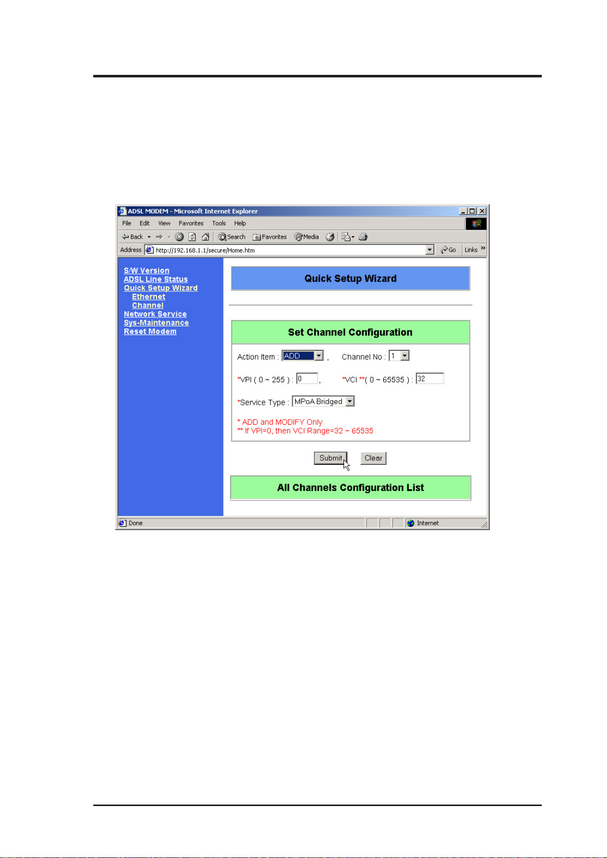
4.1 Set Channel Configuration
Your ADSL modem/router provides several channel operation modes as shown
below.
Action Item: Add, Modify, Delete
Channel No: 1-16
VPI: 0-255
VCI: 0-65535 (Except when VPI = 0, then only 32-65535)
Service Type: MPoA Bridged, MPoA Routed, IPoA Routed, PPPoA Routed,
PPPoE Relay , PPPoE Routed, MPoA Routed over MAC (optional).
Click Submit after selections are completed.
ADSL Modem/Router User’s Guide 15
Page 16

4. Basic Configuration
4.1.1 MPoA Bridged
Setup Wizard
The network configuration for this mode can be illustrated as follows. Write down
your network configuration (information supplied by your ISP or Internet Service
Provider) in the preceding table to help you gain a clearer view of your network.
PSTN
(2) WAN VPI/VCI
CONTENT PROVIDER
(3) LLC/VC MUX
POWER STATUS TESTLINE PC
ADSL MODEM
(4) PC LAN IP Address
(5) PC Default Gateway
PC
LOCAL CONTENT PROVIDER
Internet
ATM SWITCH
ROUTER/GATEWAY
DSLAM
(1) Router IP Address
Splitter
TELEPHONE
Setup Item Example Your Configuration
(1) Router IP Address 192.168.3.1
(2) WAN VPI/VCI 14/32
(3) LLC/VC MUX 1 (LLC)
(For Service Provider Use)
(Provided by ISP)
(Provided by ISP)
(4) PC LAN IP Address 192.168.3.223
(5) PC Default Gateway 192.168.3.1
16
ADSL Modem/Router User’s Guide
Page 17

4. Basic Configuration
Encapsulation Mode: AAL5 LLC/SNAP, AAL5 VC MUX,
AAL5 LLC/SNAP/VPN, AAL5 VC MUX/VPN
Click Submit after selections are completed and restart the modem.
ADSL Modem/Router User’s Guide 17
Page 18

4. Basic Configuration
4.1.2 MPoA Routed
Setup Wizard
The network configuration for this mode can be illustrated as follows. Write down
your network configuration (information supplied by your ISP or Internet Service
Provider) in the preceding table to help you gain a clearer view of your network.
(2) WAN VPI/VCI
(3) WAN IP Address
(4) LLC/VC MUX
PSTN
CONTENT PROVIDER
(5) Default Gateway IP Address
(6) Ethernet IP Address
POWER STATUS TESTLINE PC
ADSL MODEM
(7) PC LAN IP Address
(8) PC Default Gateway
PC
LOCAL CONTENT PROVIDER
Internet
ATM SWITCH
ROUTER/GATEWAY
DSLAM
(1) Router IP Address
Splitter
TELEPHONE
Setup Item Example Your Configuration
(1) Router IP Address 192.168.3.1
(For Service Provider Use)
(2) WAN VPI/VCI 14/32
(3) WAN IP Address 192.168.3.223
(4) LLC/VC MUX 1 (LLC)
(5) Default Gateway IP Address 192.168.3.1
(6) Ethernet IP Address 192.168.31.228
(7) PC LAN IP Address 192.168.31.223
(8) PC Default Gateway 192.168.31.228
18
ADSL Modem/Router User’s Guide
Page 19

4. Basic Configuration
Encapsulation Mode: AAL5 LLC/SNAP, AAL5 VC MUX,
AAL5 LLC/SNAP/VPN, AAL5 VC MUX/VPN
WAN IP Address: IP address used on the WAN (line) interface
(Provided by your Internet Service Provider)
Subnet Mask: Subnet mask on the WAN (line) interface
(Provided by your Internet Service Provider)
Function: NAT (Network Address Translation) - check to enable.
Click Submit after selections are completed and restart the modem.
NOTE: You must also setup the Ethernet Configuration and setup the Default
Gateway in the Routing Table Maintenance.
ADSL Modem/Router User’s Guide 19
Page 20

4. Basic Configuration
4.1.3 IPoA Routed
Setup Wizard
The network configuration for this mode can be illustrated as follows. W rite down
your network configuration (information supplied by your ISP or Internet Service
Provider) in the preceding table to help you gain a clearer view of your network.
(2) Support InATMARP?
(3) Remote IP Address
(4) WAN VPI/VCI
(5) WAN IP Address
PSTN
CONTENT PROVIDER
(6) Ethernet IP Address
(7) Default Gateway IP Address
POWER STATUS TESTLINE PC
ADSL MODEM
(8) PC LAN IP Address
(9) PC Default Gateway
PC
LOCAL CONTENT PROVIDER
Internet
ATM SWITCH
ROUTER/GATEWAY
DSLAM
(1) Router IP Address
Splitter
TELEPHONE
Setup Item Example 1 Example 2 Your Configuration
(1) Router IP Address 192.168.3.1 192.168.3.1
(for Service Provider Use)
(2) Support InATMARP? Yes No
(3) Remote IP Address N/A 192.168.3.2
(4) WAN VPI/VCI 14/32 14/32
(5) WAN IP Address 192.168.3.223 192.168.3.223
(6) Ethernet IP Address 192.168.31.228 192.168.31.228
(7) Default Gateway IP Address 192.168.3.1 192.168.3.1
(8) PC LAN I P Address 192.168.31.223 192.168.31.223
(9) PC Default Gateway 192.168.31.228 192.168.31.228
20
ADSL Modem/Router User’s Guide
Page 21

4. Basic Configuration
WAN IP Address: IP address used on the WAN (line) interface
(Provided by your Internet Service Provider)
Subnet Mask: Subnet mask on the WAN (line) interface
(Provided by your Internet Service Provider)
Remote IP Address From:inATMARP - Use inverse ATMARP protocol to determine
the IP address
Static Remote IP Address - Specify the IP address of the
remote end.
Function: NAT (Network Address Translation) - check to enable.
Click Submit after selections are completed and restart the modem.
NOTE: You must also setup the Ethernet Configuration and setup the Default
Gateway in the Routing Table Maintenance.
ADSL Modem/Router User’s Guide 21
Page 22

4. Basic Configuration
4.1.4 PPPoA Routed
Setup Wizard
The network configuration for this mode can be illustrated as follows. Write down
your network configuration (information supplied by your ISP or Internet Service
Provider) in the preceding table to help you gain a clearer view of your network.
(1) WAN VPI/VCI
(2) Login Username
(3) Login Password
PSTN
CONTENT PROVIDER
(4) Get IP Address Type
(5) Ethernet IP Address
POWER STATUS TESTLINE PC
ADSL MODEM
(6) PC LAN IP Address
(7) PC Default Gateway
PC
LOCAL CONTENT PROVIDER
Internet
ATM SWITCH
ROUTER/GATEWAY
Splitter
DSLAM
TELEPHONE
Setup Item Example Your Configuration
(1) WAN VPI/VCI 14/32
(For Service Provider Use)
(2) Login User Name adsl
(3) Login Password adsl
(4) Get IP Address Type 1 (Service Provider)
(5) Ethernet IP Address 192.168.31.228
(6) PC’s LAN IP Address 192.168.31.223
(7) PC’s Default Gateway 192.168.31.228
22
ADSL Modem/Router User’s Guide
Page 23

4. Basic Configuration
User Name: Enter the name required to login to your service provider.
Password: Enter the password required to login to your service provider.
Confirm Password: Enter the password again.
Encapsulation Mode: Auto, LLC, VC MUX, VC MUX + HDLC
Get IP Address from: Service Provider - Remote server will automatically assign
WAN IP Address.
Customized - User can enter a WAN IP Address below.
WAN IP Address: Manually specify a WAN IP address (must also setup the De-
fault Gateway in the Routing Table Maintenance)
PPP startup status: Up - login to service provider after connection is established
Down - don’t login to service provider after connection is established
DOD: Enable - Bring up PPP when network activity is detected
Disable - Do not use dial-up on demand
Idle Timeout: Disconnect automatically when connected computers reach this
amount of inactivity time.
Function: NAT (Network Address Translation) - check to enable.
Click Submit after selections are completed and restart the modem.
NOTE: You must also setup the Ethernet Configuration and setup the Default Gateway in the Routing T able Maintenance (Default Gate required for manual WAN IP).
ADSL Modem/Router User’s Guide 23
Page 24

4. Basic Configuration
4.1.5 PPPoE Relay
Setup Wizard
The network configuration for this mode can be illustrated as follows. Write down
your network configuration (information supplied by your ISP or Internet Service
Provider) in the preceding table to help you gain a clearer view of your network.
PSTN
(3) WAN VPI/VCI
CONTENT PROVIDER
(4) LLC/VC MUX
POWER STATUS TESTLINE PC
ADSL MODEM
(5) Login Username
(6) Login Password
PC
LOCAL CONTENT PROVIDER
Internet
ATM SWITCH
ROUTER/GATEWAY
(1) Access Concentrator Name
(2) Service Name
Splitter
DSLAM
TELEPHONE
Setup Item Example Your Configuration
(1) Access Concentrator Name ADSL_TEST_SVR
(2) Service Name Test
(3) WAN VPI/VCI 14/32
(4) LLC/VC MUX 1 (LLC)
(5) Login Username Test
(6) Login Password Test
24
ADSL Modem/Router User’s Guide
Page 25

4. Basic Configuration
Encapsulation Mode: AAL5 LLC/SNAP , AAL5 VC MUX, AAL5 LLC/SNAP/VPN,
AAL5 VC MUX/VPN
Click Submit after selections are completed and restart the modem.
IMPORTANT! Besides configuring the modem with the Setup Wizard, you also
need to install a PPPoE client program. The Login User Name, Login Password,
Access Concentrator Name, and Service Name are set in the PPPoE client program.
If you are not sure how to do this, please consult your service provider.
ADSL Modem/Router User’s Guide 25
Page 26

4. Basic Configuration
4.1.6 PPPoE Routed
Setup Wizard
The network configuration for this mode can be illustrated as follows. Write down
your network configuration (information supplied by your ISP or Internet Service
Provider) in the preceding table to help you gain a clearer view of your network.
(3) WAN VPI/VCI
(4) LLC/VC MUX
(5) Login Username
(6) Login Password
Splitter
TELEPHONE
(7) Ethernet IP Address
POWER STATUS TESTLINE PC
ADSL MODEM
(8) PC LAN IP Address
(9) PC Default Gateway
PC
CONTENT PROVIDER
LOCAL CONTENT PROVIDER
Internet
PSTN
ATM SWITCH
ROUTER/GATEWAY
(1) Access Concentrator Name
(2) Service Name
DSLAM
Setup Item Example Your Configuration
(1) Access Concentrator Name ADSL_TEST_SVR
(2) Service Name Test
(3) WAN VPI/VCI 14/32
(4) LLC/VC MUX 1 (LLC)
(5) Login Username Test
(6) Login Password Test
(7) Ethernet IP Address 192.168.31.228
(8) PC LAN IP Address 192.168.31.223
(9) PC Default Gateway 192.168.31.228
26
ADSL Modem/Router User’s Guide
Page 27

4. Basic Configuration
User Name: Enter the name required to login to your service provider.
Password: Enter the password required to login to your service provider.
Confirm Password: Enter the password again.
Get IP Address from: Service Provider - Remote server will automatically assign
WAN IP Address.
Customized - User can enter a WAN IP Address below.
WAN IP Address: Manually specify a WAN IP address (must also setup the De-
fault Gateway in the Routing Table Maintenance)
(Provided by your Internet Service Provider)
Access Concentrator Name: Manually specify the name of the server.
Service Name: Manually specify the name of the service.
PPP startup status: Up - login to service provider after connection is established
Down - don’t login to service provider after connection is established
DOD: Enable - Bring up PPP when network activity is detected
Disable - Do not use dial-up on demand
Idle Timeout: Disconnect automatically when connected computers reach this
amount of inactivity time.
Function: NAT (Network Address Translation) - check to enable.
Click Submit after selections are completed and restart the modem.
NOTE: You must also setup the Ethernet Configuration and setup the Default Gateway in the Routing T able Maintenance (Default Gate required for manual WAN IP).
ADSL Modem/Router User’s Guide 27
Page 28

4. Basic Configuration
4.1.7 MPoA Routed over MAC
Setup Wizard
The network configuration for this mode can be illustrated as follows. Write down
your network configuration (information supplied by your ISP or Internet Service
Provider) in the preceding table to help you gain a clearer view of your network.
(2) WAN VPI/VCI
(3) WAN IP Address
(4) LLC/VC MUX
PSTN
CONTENT PROVIDER
(5) Default Gateway IP Address
(6) Ethernet IP Address
POWER STATUS TESTLINE PC
ADSL MODEM
(7) PC LAN IP Address
(8) PC Default Gateway
PC
LOCAL CONTENT PROVIDER
Internet
ATM SWITCH
ROUTER/GATEWAY
DSLAM
(1) Router IP Address
Splitter
TELEPHONE
Setup Item Example Your Configuration
(1) Router IP Address 192.168.3.1
(For Service Provider Use)
(2) WAN VPI/VCI 14/32
(3) WAN IP Address 192.168.3.223
(4) LLC/VC MUX 1 (LLC)
(5) Default Gateway IP Address 192.168.3.1
(6) Ethernet IP Address 192.168.31.228
(7) PC LAN IP Address 192.168.31.223
(8) PC Default Gateway 192.168.31.228
28
ADSL Modem/Router User’s Guide
Page 29

4. Basic Configuration
Get IP Address from: Service Provider - Remote server will automatically assign
WAN IP Address.
Customized - User can enter a WAN IP Address below.
WAN IP Address: Manually specify a WAN IP address
(Provided by your Internet Service Provider)
Subnet Mask: Subnet mask on the WAN (line) interface
(Provided by your Internet Service Provider)
Function: NAT (Network Address Translation) - check to enable.
Click Submit after selections are completed and restart the modem.
NOTE: You must also setup the Ethernet Configuration and setup the Default
Gateway in the Routing Table Maintenance.
ADSL Modem/Router User’s Guide 29
Page 30

4. Basic Configuration
4.2 Set Ethernet Configuration
The Ethernet interface setting and the user’s LAN can be illustrated as follows:
PSTN
(1) Modem Ethernet IP Address
CONTENT PROVIDER
POWER STATUS TESTLINE PC
ADSL MODEM
(2) PC Ethernet IP Address
(3) PC Default Gateway
LOCAL CONTENT PROVIDER
Internet
ATM SWITCH
ROUTER/GATEWAY
Splitter
DSLAM
TELEPHONE
Ethernet Setup Example Your Configuration
(1) Modem Ethernet IP Address 192.168.31.228
(2) PC Ethernet IP Address 192.168.31.223
(3) PC Default Gateway 192.168.31.228
Set Ethernet Configuration lets you set the following:
PC
30
NOTE: The web console HTTP address and the modem’s default Ethernet IP
address are both 192.168.1.1. Your computer will require TCP/IP settings to
match TCP/IP settings made here.
ADSL Modem/Router User’s Guide
Page 31

4. Basic Configuration
4.3 Routing Table Maintenance
Routing Table List: This displays existing routing table entries. When you submit
this form, it will appear here.
Action Item: Print, Add (but not saved), Delete, Flush, Save (saved to flash
memory)
Name Index: Arbitrary name specified to “Add” that can be used to delete
the route using “Delete”.
Destination Address: The IP address of the network being routed to.
Netmask: The subnet mask of the network being routed to.
Gateway Address: The IP address of the next-hop gateway for the route.
Metric: The number of hops counted as the cost of the route.
Note: To setup a default gateway, use the following settings:
Action Item: Add Name Index:Default
Destination Address: 0.0.0.0 Netmask: 0.0.0.0
Gateway Address: [Router’s IP address] Metric: 1
Action Item: Save
ADSL Modem/Router User’s Guide 31
Page 32

5. Software Upgrade
5.1 Using ADSL Modem Upgrade Utility
A user-friendly software upgrade utility is provided that allows firmware upgrade through
the LAN port (cannot upgrade through the USB port). You can see your firmware version when you first login to the ADSL Modem through the W eb Console.
1. Set the TCP/IP of the computer and
ADSL Modem to the same subnet (e.g.
192.168.1.1 & 192.168.1.2).
2. Restart or power ON the ADSL Modem
if necessary (wait about 30sec for the
self-test to complete). You can verify
your settings by using “ping” to the ADSL
Modem (e.g. c:\ping 192.168.1.1).
3. Run the ADSL Modem Upgrade Utility
on your computer and enter the ADSL
Modem’s IP, Name, Password.
4. Use the Open button to find the new
firmware file (“hex” extension).
5. Click Upgrade to see another window .
Check both Modem image and Con-
figuration
6. Click OK to start the firmware download.
7. After the firmware is downloaded suc-
cessfully , it will take about 40 seconds
to upgrade the ADSL Modem. The
ADSL Modem will auto reboot after the
upgrade is completed.
ADSL Modem/Router
LAN
8. Enter the web console to restore fac-
tory default values. Click Sys-Mainte-
nance | Factory Default | Submit.
9. After reboot, all previous user-entered
settings will be cleared.
10.You may need to update your TCP/IP
settings and use the default user name
/ password to access the web console.
11. After the firmware upgrade is com-
pleted, you may use the Web console
to set up the ADSL modem again as
instructed in this User’s Manual.
32
ADSL Modem/Router User’s Guide
Page 33

5. Software Upgrade
5.2 Using BootP / TFTP Servers
About BootP and TFTP Servers
The BootP and TFTP servers are used to transfer the configuration and application
information to the Gateway through the Ethernet connection. The BootP server
provides the IP address for the Gateway. The TFTP server provides the application
and configuration for the Gateway.
1. Download an updated software image file from your Service Provider and save it to
your hard drive.
2. Make sure the HUB-PC switch of your ADSL Modem/Router is in the PC position (PC
Link LED should be ON).
3. Make sure the modem is connected to your PC through the Ethernet interface and the
Console Port on the modem is connected to your PC’s COM port.
4. Run a terminal emulation program such as HyperTerminal.
5. Run a BOOTP server program. Configure your BOOTP server. Enter the update
filename, the MAC address of your modem and assign an IP address to the modem.
6. Run a TFTP server program. Configure your TFTP server , for example, the root directory .
Most BOOTP and TFTP services can be used. Some software even combine both a
BOOTP server and TFTP server. (The following diagram should be regarded as a
general reference only. The basic procedures, however, are similar for any BootP
server).
ADSL Modem/Router User’s Guide 33
Page 34

5. Software Upgrade
Enter the MAC address
labeled on the back of
your ADSL modem.
Assign a new IP
to the modem.
Type the location and name
of the updated FLASH file you
saved on your computer.
Make sure to select
Broadcast Reply to
BootP Requests
7. Press the reset button on the modem while pressing the asterisk key <*> in your
terminal emulation program. When you are prompted to “Boot from Ethernet, USB or
Flash”, type E because the modem is connected to your computer through the Ethernet interface.
34
ADSL Modem/Router User’s Guide
Select BootP Server
for configuration
Select BootP Server
for configuration
Page 35

5. Software Upgrade
8. The modem will then boot from the Ethernet and automatically start downloading the
software image file from the computer.
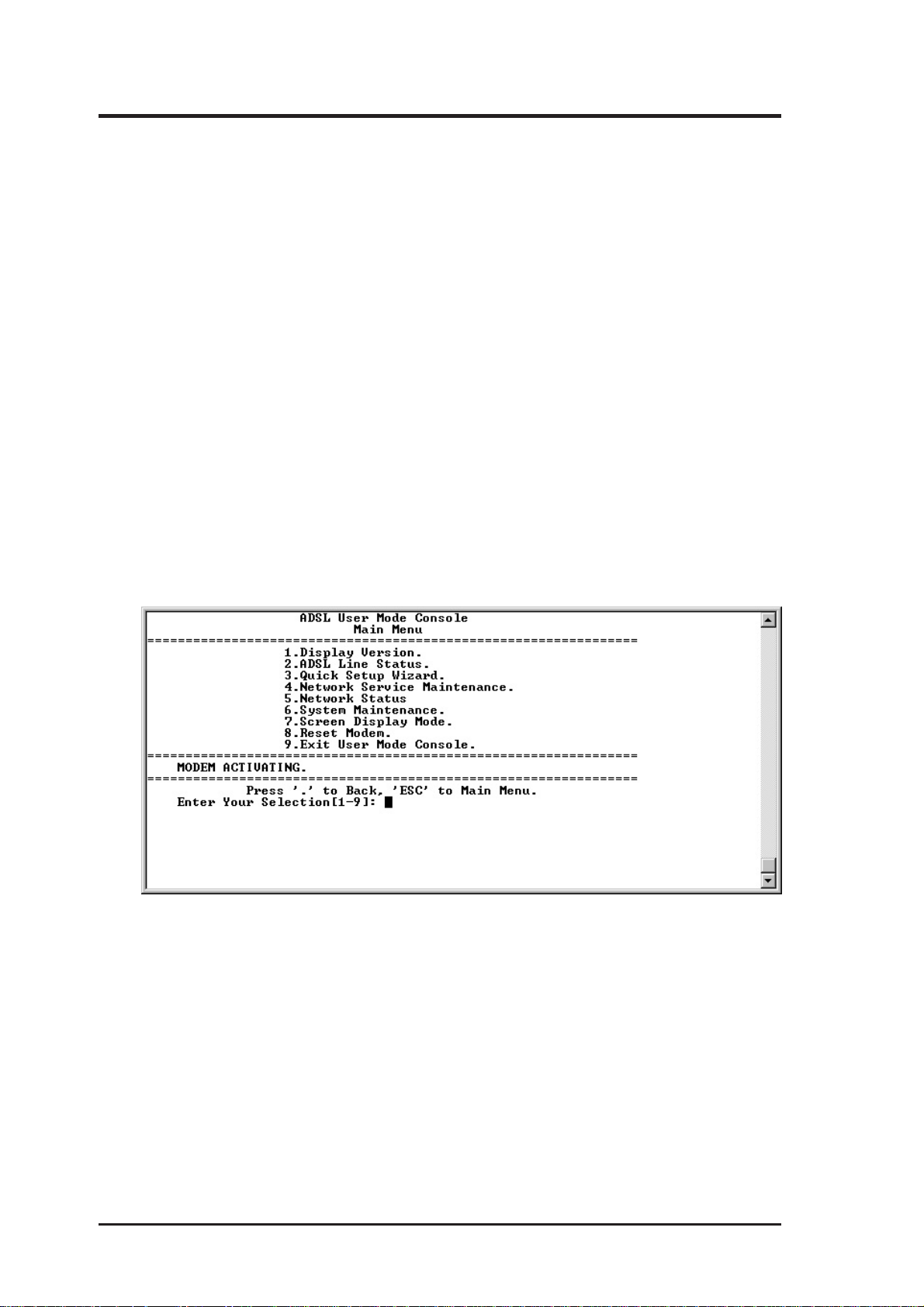
9. When the file is successfully downloaded, the main menu of the updated console will
be launched.
10.In Main Menu, enter 6 for System Maintenance.
11.In System Maintenance Menu, enter 3 for Firmware Update. The software update is
now completed.
12.Enter 2 to load the Factory Default Configuration.
13.The modem will restart automatically after the default configuration is saved.
14.The software update is completed when the modem reenters the Main Menu.
ADSL Modem/Router User’s Guide 35
Page 36

36
ADSL Modem/Router User’s Guide
Page 37

Appendix
Appendix
USB Combo Series
The optional USB Combo Series provides a USB port along with the LAN
port. By factory default, the USB port is disabled. If you wish to use the
USB port, the USB port must be mounted as a ‘bridged device” or as a
“routed device” on the ADSL Modem/Router. One computer can use the
LAN port and another computer can use the USB port. The computer using
the USB port must install the provided drivers for your W indows
or 2000 operating system.
This chapter gives step-by-step procedures on mounting the USB port
through the Web Console and driver installations under the Windows
erating systems. However, details on Network Services applied to the USB
port are outside the scope of this document.
®
98, ME,
®
op-
ADSL Modem/Router User’s Guide 37
Page 38

Appendix
Mounting the USB Port
1. Connect your ADSL Modem/Router as
shown here. The LAN port is used to
configure the ADSL modem/router before the USB port is activated. Afterwards, the LAN port (1) can be used by
one computer and the USB port (2) can
be used by a second computer for LAN
and Internet connections.
2. From Chapter 3, your Local Area Con-
nection for the LAN connected computer
should have TCP/IP settings similar to
192.168.1.10, 255.255.255.0
3. Open your Web browser (e.g. Internet
Explorer), on the computer connected to
the LAN port. Type the IP address (e.g.
192.168.1.1) of the ADSL modem/router
to link to the web console. The default
name/password is adsl / adsl1234.
ADSL Modem/Router
(USB Combo Series)
USB
LAN
2
USB
Driver
1
Web
Browser
3. Click on Quick Setup Wizard | USB
on the left column to enter “Set USB
Configuration” page. The default USB
status is None.
4. Bridged Mode: When the USB port is
operating in the Bridged Mode, there is
no need to assign any IP address to the
USB interface. The “IP Address” and
“Subnet Mask” should be left blank.
Click “Submit” to save settings.
38
ADSL Modem/Router User’s Guide
Page 39

Appendix
5. Routed Mode: When the USB port is
operating in the Routed Mode, you need
to assign a different (from 192.168.1.1
used by LAN port) IP address and subnet
mask to the interface. The PC connecting to the USB port lies in a different
subnet from the Ethernet network. The
ADSL modem/router will provide the
routing function between the two local
networks.
Click “Submit” to save settings.
6. The USB port will be activated after your
ADSL Modem/Router is restarted.
7. For a computer to use the ADSL Mo-
dem/Router’s USB port, USB drivers
must be installed as instructed later.
DHCP Server (Routed Mode Only)
The dynamic IP address assignment for a
computer connected through the USB port
is available only if the USB port is operating in Routed Mode. Remember to select
USB interface under Network Services |
DHCP Server Configuration.
If you did not set Routed Mode, the Interface selection will only show Ethernet.
ADSL Modem/Router User’s Guide 39
Page 40

Appendix
Installing USB Drivers
The USB port on the ADSL Modem/Router must be mounted before installing the drivers.
The USB drivers consist for two parts, “ADSL USB VVBus” and “ADSL
VVB gateway”. After installing the drivers, the USB port will simulate a
Network Adapter in the system and users can set up and monitor the USB
port like a network card. Both drivers must be installed.
Installation in Windows ME
1. Startup your computer into Windows.
2. Connect the ADSL Router power port
to an electrical outlet and connect the
USB port to your computer’s USB port.
3. When the “Add New Hardware Wizard”
has found “ADSL USB Modem”, insert
the driver floppy into Floppy A, and select Automatic search for a better
driver (Recommended) and press Next.
4. Windows will begin to search for the
driver and install it automatically. After
several seconds, a message will be
shown to indicate the installation is completed.
5. Press Finish to complete the “ADSL
VVBus” driver installation.
40
ADSL Modem/Router User’s Guide
Page 41

Appendix
6. Then, Windows will detect the second
device, “ADSL VVB gateway”.
7. Similarly, select Automatic search for
a better driver (Recommended) and
press Next.
8. Press Finish to complete the “ADSL
VVB gateway” driver installation.
9. Restart your computer to load the drivers.
ADSL Modem/Router User’s Guide 41
Page 42

Appendix
Verifying Drivers and IP in Windows ME
1. Right-click My Network Places on the
desktop and click Properties. Y ou should
see “ADSL VVB PC-attached gateway”.
2. Scroll down and you should find “TCP/
IP->ADSL VVB PC-attached gateway”.
Double-click this item.
3. Click IP Address. If the DHCP server
function is turned ON (Part 1), you may
choose Obtain IP address automati-
cally. Otherwise, you need to select
Specify an IP address and enter the IP.
(e.g. 111.112.34.100, 255.255.255.0)
4. Press OK to complete the configuration.
The new settings will take effect your
computer restarts.
5. After your computer restarts, enter MSDOS prompt and type ipconfig to verify
the IP setting.
6. You can also try to “ping” a remote site.
If you receive replies from the remote
site, your ADSL router is working.
Type ipconfig and look for the set IP.
Type ping and a site name or IP address.
42
ADSL Modem/Router User’s Guide
Page 43

Appendix
Installation in Windows 2000
1. Startup your computer into Windows.
2. Connect the ADSL Router power port
to an electrical outlet and connect the
USB port to your computer’s USB port.
3. When the “Add New Hardware Wizard”
has found “USB Modem”, click Next to
begin driver installation.
4. Insert the driver disk into your floppy
drive “A”, and select Search for a suit-
able driver...” and press Next.
5. Check Floppy disk drives and deselect
all others. Click Next.
6. V erify the driver location and click Next.
7. Press Finish to complete the “ADSL
VVBus” driver installation.
ADSL Modem/Router User’s Guide 43
Page 44

Appendix
Installation in Windows 2000 (Cont’)
8. Then, Windows will detect the second
device, “ADSL VVB gateway”.
9. Click Next. (The driver disk should still
be in your drive “A”.)
10.The “Found New Hardware Wizard”
will ask for a command. Select Search
for a suitable driver for my device
(recommended) and press Next.
11.Check Floppy disk drives and deselect
all others. Click Next.
12.Verify the driver source and click Next.
44
ADSL Modem/Router User’s Guide
Page 45

Appendix
Installation in Windows 2000 (Cont’)
13. When you see “Digital Signature Not
Found”, click Yes because this driver has
been fully tested by the manufacturer for
the operating systems mentioned in this
manual.
14.When the driver installation has finished,
click Finish to exit the wizard.
Stopping the ADSL Modem/Router USB Device
For computers using ADSL
Modem/Router USB Port:
Before unplugging your ADSL
Modem/Router’s power or USB
cable, you must stop the device.
Left-click the removable device
icon on the taskbar and select the
device to stop.
This screen is shown if you do not
do so.
ADSL Modem/Router User’s Guide 45
Page 46

Appendix
Verifying Drivers and IP in Windows 2000
1. Right-click My Network Places on the
desktop and click Properties.
2. You should see “Local Area Connection”. You can rename this to “USB
ADSL” or whatever you like.
3. Right click this item and select Proper-
ties.
4. Scroll down and you should find “Inter-
net Protocol (TCP/IP)”. Double-click
this item.
5. Check the IP Address. If the DHCP
server function is turned ON (Part 1),
you may choose Obtain IP address au-
tomatically. Otherwise, you need to select Specify an IP address and enter the
IP. (e.g. 192.168.2.10 / 255.255.255.0 /
192.168.2.1). Click OK to save.
6. Enter MS-DOS prompt and type
ipconfig to verify the IP setting.
7. You can also try to “ping” a remote site.
If you receive replies from a remote site,
your ADSL router is working.
Type ipconfig and look for the set IP.
Type ping and a site name or IP address.
46
ADSL Modem/Router User’s Guide
Page 47

Appendix
ADSL-Related Acronyms
ADSL Asymmetric Digital Subscriber Line
ANSI American National Standards Institute
ARP Address Resolution Protocol
ATM Asynchronous Transfer Mode
BootP Bootstrap Protocol
CHAP Challenge-Handshake Authentication Protocol
DHCP Dynamic Host Configuration Protocol
DMT Discrete Multi-Tone
DSLAM Digital Subscriber Line Access Multiplexer
IETF RFC Internet Engineering Task Force Request for Comments
IPCP Internet Protocol Control Protocol
IPoA IP over ATM
ITU International Telecommunication Union
ITU-T ITU Telecommunication Standardization Sector
MAC (address)Media Access Control (address)
MPoA Multiprotocol Encapsulation over ATM Adaptation Layer 5
(AAL5)
NAT Network Address Translation
PAP Password Authentication Protocol
POTS Plain Old Telephone Service
POP Point-to-Point Protocol
PPPoA PPP over ATM Adaptation Layer 5
PPPoE PPP over Ethernet
PSTN Public Switched Telephone Network
PVC Permanent V irtual Connection
Telco Telephone Company
TCP/IP Transmission Control Protocol/Internet Protocol
TFTP Trivial File Transfer Protocol
VCI Virtual Circuit Identifier
VPI Virtual Path Identifier
WAN W ide Area Network
ADSL Modem/Router User’s Guide 47
Page 48

15-068017000
 Loading...